EP2953771B1 - Cutting block for food products - Google Patents
Cutting block for food products Download PDFInfo
- Publication number
- EP2953771B1 EP2953771B1 EP14749267.2A EP14749267A EP2953771B1 EP 2953771 B1 EP2953771 B1 EP 2953771B1 EP 14749267 A EP14749267 A EP 14749267A EP 2953771 B1 EP2953771 B1 EP 2953771B1
- Authority
- EP
- European Patent Office
- Prior art keywords
- support
- blades
- cutting block
- along
- length
- Prior art date
- Legal status (The legal status is an assumption and is not a legal conclusion. Google has not performed a legal analysis and makes no representation as to the accuracy of the status listed.)
- Active
Links
Images



Classifications
-
- B—PERFORMING OPERATIONS; TRANSPORTING
- B26—HAND CUTTING TOOLS; CUTTING; SEVERING
- B26D—CUTTING; DETAILS COMMON TO MACHINES FOR PERFORATING, PUNCHING, CUTTING-OUT, STAMPING-OUT OR SEVERING
- B26D1/00—Cutting through work characterised by the nature or movement of the cutting member or particular materials not otherwise provided for; Apparatus or machines therefor; Cutting members therefor
- B26D1/01—Cutting through work characterised by the nature or movement of the cutting member or particular materials not otherwise provided for; Apparatus or machines therefor; Cutting members therefor involving a cutting member which does not travel with the work
- B26D1/02—Cutting through work characterised by the nature or movement of the cutting member or particular materials not otherwise provided for; Apparatus or machines therefor; Cutting members therefor involving a cutting member which does not travel with the work having a stationary cutting member
- B26D1/03—Cutting through work characterised by the nature or movement of the cutting member or particular materials not otherwise provided for; Apparatus or machines therefor; Cutting members therefor involving a cutting member which does not travel with the work having a stationary cutting member with a plurality of cutting members
-
- A—HUMAN NECESSITIES
- A23—FOODS OR FOODSTUFFS; TREATMENT THEREOF, NOT COVERED BY OTHER CLASSES
- A23L—FOODS, FOODSTUFFS OR NON-ALCOHOLIC BEVERAGES, NOT OTHERWISE PROVIDED FOR; PREPARATION OR TREATMENT THEREOF
- A23L19/00—Products from fruits or vegetables; Preparation or treatment thereof
- A23L19/10—Products from fruits or vegetables; Preparation or treatment thereof of tuberous or like starch containing root crops
- A23L19/12—Products from fruits or vegetables; Preparation or treatment thereof of tuberous or like starch containing root crops of potatoes
- A23L19/14—Original non-roasted or non-fried potato pieces
-
- A—HUMAN NECESSITIES
- A23—FOODS OR FOODSTUFFS; TREATMENT THEREOF, NOT COVERED BY OTHER CLASSES
- A23P—SHAPING OR WORKING OF FOODSTUFFS, NOT FULLY COVERED BY A SINGLE OTHER SUBCLASS
- A23P30/00—Shaping or working of foodstuffs characterised by the process or apparatus
- A23P30/10—Moulding
-
- B—PERFORMING OPERATIONS; TRANSPORTING
- B26—HAND CUTTING TOOLS; CUTTING; SEVERING
- B26D—CUTTING; DETAILS COMMON TO MACHINES FOR PERFORATING, PUNCHING, CUTTING-OUT, STAMPING-OUT OR SEVERING
- B26D3/00—Cutting work characterised by the nature of the cut made; Apparatus therefor
- B26D3/10—Making cuts of other than simple rectilinear form
-
- B—PERFORMING OPERATIONS; TRANSPORTING
- B26—HAND CUTTING TOOLS; CUTTING; SEVERING
- B26D—CUTTING; DETAILS COMMON TO MACHINES FOR PERFORATING, PUNCHING, CUTTING-OUT, STAMPING-OUT OR SEVERING
- B26D7/00—Details of apparatus for cutting, cutting-out, stamping-out, punching, perforating, or severing by means other than cutting
- B26D7/06—Arrangements for feeding or delivering work of other than sheet, web, or filamentary form
- B26D7/0658—Arrangements for feeding or delivering work of other than sheet, web, or filamentary form using fluid, e.g. hydraulic, acting directly on the work
-
- B—PERFORMING OPERATIONS; TRANSPORTING
- B26—HAND CUTTING TOOLS; CUTTING; SEVERING
- B26D—CUTTING; DETAILS COMMON TO MACHINES FOR PERFORATING, PUNCHING, CUTTING-OUT, STAMPING-OUT OR SEVERING
- B26D7/00—Details of apparatus for cutting, cutting-out, stamping-out, punching, perforating, or severing by means other than cutting
- B26D7/26—Means for mounting or adjusting the cutting member; Means for adjusting the stroke of the cutting member
- B26D7/2614—Means for mounting the cutting member
-
- B—PERFORMING OPERATIONS; TRANSPORTING
- B26—HAND CUTTING TOOLS; CUTTING; SEVERING
- B26D—CUTTING; DETAILS COMMON TO MACHINES FOR PERFORATING, PUNCHING, CUTTING-OUT, STAMPING-OUT OR SEVERING
- B26D1/00—Cutting through work characterised by the nature or movement of the cutting member or particular materials not otherwise provided for; Apparatus or machines therefor; Cutting members therefor
- B26D1/0006—Cutting members therefor
- B26D2001/0033—Cutting members therefor assembled from multiple blades
-
- B—PERFORMING OPERATIONS; TRANSPORTING
- B26—HAND CUTTING TOOLS; CUTTING; SEVERING
- B26D—CUTTING; DETAILS COMMON TO MACHINES FOR PERFORATING, PUNCHING, CUTTING-OUT, STAMPING-OUT OR SEVERING
- B26D1/00—Cutting through work characterised by the nature or movement of the cutting member or particular materials not otherwise provided for; Apparatus or machines therefor; Cutting members therefor
- B26D1/0006—Cutting members therefor
- B26D2001/006—Cutting members therefor the cutting blade having a special shape, e.g. a special outline, serrations
-
- Y—GENERAL TAGGING OF NEW TECHNOLOGICAL DEVELOPMENTS; GENERAL TAGGING OF CROSS-SECTIONAL TECHNOLOGIES SPANNING OVER SEVERAL SECTIONS OF THE IPC; TECHNICAL SUBJECTS COVERED BY FORMER USPC CROSS-REFERENCE ART COLLECTIONS [XRACs] AND DIGESTS
- Y10—TECHNICAL SUBJECTS COVERED BY FORMER USPC
- Y10T—TECHNICAL SUBJECTS COVERED BY FORMER US CLASSIFICATION
- Y10T83/00—Cutting
- Y10T83/04—Processes
-
- Y—GENERAL TAGGING OF NEW TECHNOLOGICAL DEVELOPMENTS; GENERAL TAGGING OF CROSS-SECTIONAL TECHNOLOGIES SPANNING OVER SEVERAL SECTIONS OF THE IPC; TECHNICAL SUBJECTS COVERED BY FORMER USPC CROSS-REFERENCE ART COLLECTIONS [XRACs] AND DIGESTS
- Y10—TECHNICAL SUBJECTS COVERED BY FORMER USPC
- Y10T—TECHNICAL SUBJECTS COVERED BY FORMER US CLASSIFICATION
- Y10T83/00—Cutting
- Y10T83/364—By fluid blast and/or suction
-
- Y—GENERAL TAGGING OF NEW TECHNOLOGICAL DEVELOPMENTS; GENERAL TAGGING OF CROSS-SECTIONAL TECHNOLOGIES SPANNING OVER SEVERAL SECTIONS OF THE IPC; TECHNICAL SUBJECTS COVERED BY FORMER USPC CROSS-REFERENCE ART COLLECTIONS [XRACs] AND DIGESTS
- Y10—TECHNICAL SUBJECTS COVERED BY FORMER USPC
- Y10T—TECHNICAL SUBJECTS COVERED BY FORMER US CLASSIFICATION
- Y10T83/00—Cutting
- Y10T83/647—With means to convey work relative to tool station
- Y10T83/6472—By fluid current
-
- Y—GENERAL TAGGING OF NEW TECHNOLOGICAL DEVELOPMENTS; GENERAL TAGGING OF CROSS-SECTIONAL TECHNOLOGIES SPANNING OVER SEVERAL SECTIONS OF THE IPC; TECHNICAL SUBJECTS COVERED BY FORMER USPC CROSS-REFERENCE ART COLLECTIONS [XRACs] AND DIGESTS
- Y10—TECHNICAL SUBJECTS COVERED BY FORMER USPC
- Y10T—TECHNICAL SUBJECTS COVERED BY FORMER US CLASSIFICATION
- Y10T83/00—Cutting
- Y10T83/929—Tool or tool with support
- Y10T83/9493—Stationary cutter
- Y10T83/9498—Parallel cutting edges
Definitions
- This application relates to the field of cutting food products, and more specifically to the field of cutting tools for cutting food products into several fragments.
- Known cutting blocks for food products include a support extending in length parallel to a downstream direction of food products, and a plurality of blades fixed to the support and extending perpendicularly to the downstream direction.
- the blades are spaced apart from each other, and arranged in pairs.
- Such cutting blocks are described in US patent application publications 2004/0042407 and 2010/0236372 .
- the blades are arranged in rows in the general shape of a pyramid, and each pair of blades has a different downstream position.
- the food products intended to be cut using these cutting blocks are potatoes.
- the cutting block is generally positioned downstream from a hydraulic circuit including a conveyor in which the food products (e.g. potatoes) move at great speed.
- the food products are cut into fragments or small strips when they pass through the cutting block in the downstream direction.
- the blades have an undulated shape which may cut fragments having an original and decorative shape differing from the traditional rectilinear rod shape.
- US patent application publication 2010/236372 describes a blade assembly that includes a number of wave-shaped blades arranged substantially parallel to each other, and spaced laterally from each other.
- the wave-shaped blades are secured to a support.
- Each wave-shaped blade includes a number of alternating blade peaks and blade troughs.
- Each blade peak has a maximum, and each blade trough has a minimum.
- An intermediate portion of the wave-shaped blade is located between the maximum and the minimum of each adjacent blade peak and blade trough.
- a number of sectioning blades are secured to the support and arranged substantially transverse to the wave-shaped blades. The sectioning blades are aligned with the intermediate portions of the wave-shaped blades.
- embodiments disclosed herein may provide a cutting block for cutting food products into fragments having an "S" shape.
- the cutting block may include an elongate support and a plurality of parallel blades secured to the support.
- the support may have a height, a breadth, and a length, wherein the height of the support is substantially parallel to a downstream direction of the food products, and wherein the breadth and the length of the support are substantially perpendicular to the height.
- the blades may extend in a direction along the breadth of the support.
- the blades may be arranged in pairs, wherein each pair of blades is positioned along the height of the support. Each blade in the pair may be aligned along the height of the support and spaced apart along the length of the support.
- Each blade may comprise a substantially straight first outer portion, a substantially straight second outer portion parallel to the first outer portion, and a third middle portion joining the first outer portion to the second outer portion.
- the third middle portion may be inclined relative to the first and second outer portions, the first and second outer portions being spaced apart along the length of the support.
- the third middle portion may comprise first and second curved ends connected by a straight portion, wherein the first curved end is connected to the first outer portion, and the second curved end is connected to the second outer portion. At least one of the first and second outer portions of each blade may be fastened to the support.
- the "S" shape of fragments cut by the cutting block may be provided by the first, second and third portions which define the external shape of the cut fragment.
- the blades of the cutting block may also be generally "S" shaped.
- a fragment is cut from a food product by the passing of the food product between two adjacent blades of the cutting block.
- the shape of the two adjacent blades is thus imparted to the side edges of the fragment cut by those blades. Consequently, some embodiment of the cutting block described herein may cut fragments, each of which has at least one side edges that is substantially "S" shaped, similar to the shape of the blade of the cutting block.
- each blade form one and the same piece.
- each of the blades of the cutting block may be integrally formed as one piece.
- a first distance in a direction along the height of the support between the first outer portions of adjacent blades may be equal to a second distance in the direction along the height of the support between the second outer portions of adjacent blades. This may permit the cutting block to cut fragments of food products in the shape of an "S" whose end portions have the same thickness.
- a third distance between the third middle portions of adjacent blades is equal to the first distance between the first outer portions of adjacent blades. This may permit the cutting block to cut fragments of food products in the shape of an "S" having a uniform thickness across the entire length of the fragments.
- the food product is a potato which may be whole and optionally peeled.
- Embodiments of the cutting block may be used to cut fragments of potato, where each fragment has an "S" shape and a uniform thickness the entire length of the fragment. Such fragments may be used to form French-fries that are uniformly cooked along their entire lengths.
- a third distance between the straight portions of the third middle portions of adjacent blades may be equal to the first distance between the first outer portions of adjacent blades.
- each of the blades may be spaced apart from each other blade along the length of the support, and differently positioned from each other blade along the breadth of the support. This may permit several "S" shaped fragments having different shapes to be cut from the same food product. For example, the length of the end portions and inclined middle portion may differ as between fragments cut from the same food product. Still, each fragment cut by the cutting block may have the same thickness.
- the support may be solid and the cutting block may further include a base connected to the support and extending along the breadth and length of the support.
- the base may include an opening, and the blades may extend through a cylindrical volume orthogonal to the base, wherein the opening defines a transverse section of the cylindrical volume. This may permit the blades, when viewed in projection along the height of the support, to cover the opening in the base.
- the base may have a first side from which the support extends parallel to the downstream direction of the food products, and a second side opposite to the first side.
- the first side may be arranged downstream from the second side.
- the opening may be circular, and optionally centred on the base.
- the blades When the second side of the base is viewed along the downstream direction, the blades may be seen to extend across the opening to form a cutting grid.
- the straight portion of the third middle portion of each of the blades may align with a diametric line of the opening.
- the support may comprise a first support element and a second support element.
- the first and second support elements may be arranged on opposite sides of the opening.
- the first outer portion may be fixed to the first support element, and the second outer portion may be fixed to the second support element. Accordingly, the blades may extend between the first and second support elements.
- the first and second support elements may be in the shape of a pyramid.
- Each support element may have an upper side and a lower side, each side including adjacent parallel landings. The landings of the same side may be separated from each other along the length of the support.
- each side of each support element may resemble a staircase. The distance along the length of the support between adjacent landings may substantially correspond to the space between two adjacent blades, and therefore also with the thickness of a fragment cut by those blades.
- the first and second support elements when viewed along the first direction, are parallel and preferably inclined in relation to the first and second outside portions of the blades. This incline may permit adjacent blades to have a different position along the breadth of the support.
- first and second outside portions may have substantially the same length.
- the length of the third middle portion of the blades may be less than the lengths of the first and second outside portions of the blades.
- the third middle portion of each blade is connected by first and second curved ends to the first and second outside portions.
- the curved ends may contribute to the "S" shape of a fragment cut by the blades.
- the curved portions are shaped as arches.
- each blade has a first end and a second end, and the third middle portion of each blade may be located substantially equally between the first and second ends.
- the third middle portion may be inclined relative to the first outer portion at an angle of between 20° and 80° inclusive. In some embodiments, the third middle portion may be inclined relative to the first outer portion at an angle of between 50° and 75° inclusive.
- a facility for cutting products may include a food products conveyor for moving food products in a downstream direction, and an embodiment of the cutting block positioned downstream of the food products conveyor at an outlet of the food products conveyor.
- the facility may further comprise hydraulic fluid under pressure for moving food products inside of the conveyor to the cutting block.
- a method of manufacturing fragments of food products may comprise providing food products (e.g. potatoes), and directing the food products through to an embodiment of the cutting block to cut the food products into fragments.
- food products e.g. potatoes
- a use of embodiments of the cutting block is provided for cutting food products (e.g. potatoes) into fragments having an "S" shape.
- a use of the cutting block is provided for cutting food products into fragments having an "S" shape and a substantially constant thickness across their length.
- FIG. 1 shows a schematic of a food product cutting facility 100.
- Facility 100 includes a hydraulic conveyor 102 in which a hydraulic fluid F circulates to direct food products P to move in a downstream direction A.
- food products P may be whole potatoes. It will be understood by those skilled in the art that products P may be any other suitable food products, such as root vegetable products.
- Cutting facility 100 as shown also includes a cutting block 10, which is described in more detail below.
- Cutting block 10 is located at a downstream end 102a of conveyor 102.
- the flow of hydraulic fluid F provides a means for moving potatoes P inside conveyor 102 towards cutting block 10.
- the flow of hydraulic fluid F may accelerate whole potatoes P and guide them in the downstream direction A through cutting block 10.
- Cutting block 10 in this example cuts potatoes P into fragments P1, P2, P3, P4, and P5.
- An outlet tube 104 is connected to the outlet of cutting block 10. Outlet tube 104 may guide potato fragments P towards a sorting station (not shown), for example.
- Figure 1 also illustrates a process for manufacturing food product fragments using a cutting block 10 in accordance with at least one embodiment.
- fragments P1-P5 of potatoes P are intended to be used for making French fries.
- Figure 1A shows a fragment P3 cut from potato P by cutting block 10. As shown, fragment P3 has an "S" shape, and a thickness e which is significantly constant throughout the length of fragment P3.
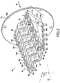
- cutting block 10 is substantially pyramidal shaped with a disc-shaped base 12, and a support 14 which extends substantially perpendicularly from base 12.
- Base 12 includes a first side 12a from which support 14 extends substantially perpendicularly, and a second side 12b opposed to first side 12a.
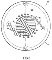
- Base 12 further includes a substantially circular opening 16, better visible on Figure 6 , through which food products P may enter into cutting block 10.
- a height H of support 14 extends in a first direction D1 substantially parallel to downstream direction A of food products P.
- Second side 12b of base 12 of cutting block 10 may be fixed to downstream end 102a of the conveyor 102.
- support 14 includes a first support element 18 and a second support element 20.
- first and second support elements 18 and 20 are arranged on both sides of the opening 16, and extend substantially perpendicularly from first side 12a of base 12 in parallel with each other.
- first and second support elements 18 and 20 are substantially pyramidal shaped. As first and second support elements 18 and 20 are preferably identical, only the first support element 18 will be described in detail.
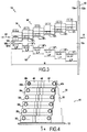
- First support element 18 is substantially pyramidal shaped, having a height H substantially perpendicular to first side 12a of base 12, a breadth I substantially perpendicular to height H, and a length L also substantially perpendicular to height H.
- Breadth I is the distance between the first support element 18 and second support element 20.
- Breadth I is preferably constant along the entire height H of each support element 18, 20.
- Length L optionally decreases along height H from first end 18a fixed to the base 12, towards second end 18b opposed to first end 18a. As shown in Figure 3 , height H corresponds to the distance between first and second ends 18a and 18b of first support element 18.
- first support element 18 includes an upper side 18' and a lower side 18".
- Each of the upper 18' and lower 18" sides are in the shape of a stairway with a first series of parallel and adjacent landings 18' 1 , 18' 2 , 18' 3 , 18' 4 , 18' 5 and 18' 6 on upper side 18', and a second series of parallel and adjacent landings 18" 1 , 18" 2 , 18" 3 , 18" 4 , 18" 5 and 18" 6 on lower side 18".
- Two adjacent landings are separated by a projection forming a step.
- each of landings 18' 1 , 18' 2 , 18' 3 , 18' 4 , 18' 5 and 18' 6 has the same length LP and the same breadth I.
- first support element 18 includes six pairs of landings 18' and 18". However, in alternative embodiments, there may be fewer or a greater number of pairs of landings 18' and 18".
- first support element 18 is such that the distance (length L) between a landing 18' n on upper side 18' and a landing 18" n on a lower side 18" decreases for landings 18' n and 18" n toward second end 18b of first support element 18.
- a distance X2 between the second landing 18' 2 of upper side 18' and second landing 18" 2 of lower side 18" is less than a distance X1, between first landing 18' 1 of upper side 18' and first landing 18" 1 of the lower side 18".
- first support element 18 when viewed in downstream direction A, is substantially parallelogram-shaped, having an internal angle of about 45° in the embodiment shown. The significance of this parallelogram shape is described in more detail below.
- second support element 20 is preferably identical to first support element 18. Therefore, the second support element 20 may include the same series of landings as are found on first support element 18.
- Cutting block 10 also includes a plurality of parallel blades 30 and 32.
- Each blade 30 and 32 is fixed to support 14 and extends along the breadth of support 14 perpendicularly to direction D1.
- Each of the blades 30 and 32 has a surface extending in direction D1 and perpendicular to side 12a of base 12.
- each of blades 30 and 32 is spaced apart from each other blade 30 and 32 along the length L of support 14, and blades 30 and 32 are arranged in pairs of blades 30 i and 32 i .
- Each pair of blades 30 i and 32 i is aligned along the height H of support 14.
- blades 30 and 32 include a first pair of blades 30 1 and 32 1 consisting of the blades positioned closest to base 12.
- a second pair 30 2 and 32 2 is positioned next to first pair of blades 30 1 and 32 1 .
- the other four pairs of blades are similarly arranged. As shown, the blades within the same pair of blades are parallel to each other and parallel to the blades of the other pairs of blades.
- all blades 30 and 32 of cutting block 10 are identical. That is, the blades 30 and 32 in the same pair are identical to each other, and also identical to the blades 30 and 32 in each of the other pairs.
- each blade 30 and 32 includes a substantially straight first outer portion 40, a substantially straight second outer portion 42 parallel to the first outer portion 40, and a third middle portion 44 joining the first and second outer portions 40 and 42.
- third middle portion 44 is inclined relative to first and second outer portions 40 and 42.
- first and second outer portions 40 and 42 are spaced apart along length L of support 14.
- Each third middle portion 44 includes first and second curved ends 44b and 44d connected by a straight portion 44a. As better seen in Figure 5B , first curved end 44b is connected to first outer portion 40, and second curved end 44d is connected to second outer portion 42. Straight portion 44a extends at an incline relative to first and second outer portions 40 and 42.
- each blade has a first end 42a and a second end 42b.
- Third middle portion 44 may be located substantially equally between first and second ends 42a and 42b.
- first and second outer portions 40 and 42 have substantially the same length.
- third middle portion 44 has a length less than the length of first and second outer portions 40 and 42.
- third middle portion 44, or more particularly straight portion 44a of middle portion 44 is inclined relative to first outer portion part 40 at an angle ⁇ .
- angle ⁇ is between about 20° and 80° inclusive, or more preferably between about 50° and 75° inclusive. In the example shown, angle ⁇ is approximately 60°.
- At least one of the first and second outer portions 40 and 42 is fastened to support 14.
- first outer portion 40 of each of blades 30 and 32 is fastened to first support element 18 and second outer portion 42 of each blade 30 and 32 is fastened to second support element 20.
- each third middle portion 44 aligns with a diametric line K of opening 16.
- each first outer portion 40 of the blades 30 i is fastened to one of landings 18' i on upper side 18' of first support element 18.
- each second outer portion 42 of blades 32 i is fastened to one of landings 18" i on the lower side 18" of the first support element 18.
- each second outer portion 42 of the blades 30 i is fastened to one of the landings on the upper side 20' of second support element 20.
- each second outer portion 42 of the blades 32 i is fastened to one of the landings on the lower side 20" of second support element 20.
- blades 30 and 32 are fastened to first and second support element 18 and 20 by bolts 50.
- the spacing being any two adjacent blades 30 or 32 may be constant throughout the length of the two blades 30 or 32.
- adjacent blades are fastened to the same side (upper or lower) of first and second support elements 18 and 20, except for blades 30 6 and 32 6 located at second end 18b opposite to base 12 which are considered to be adjacent despite being fastened to opposite sides of first and second support elements 18 and 20.
- a distance d between the first outer portions 40 of two adjacent blades is equal to the distance d between the second outer portions 42 of the same adjacent blades 30 1 and 30 2 . This may be true for every two adjacent blades 30 or 32.
- the distance d between the third middle portions 44 of two adjacent blades 30 or 32 may also be equal to the distance d between the first outer portions 40 of the same two adjacent blades 30 or 32.
- the distance d between the third middle portions 44 of two adjacent blades 30 or 32 is measured between the straight portions 44a of the third middle portions 44 of the two adjacent blades 30 or 32.
- blades 30 and 32 when viewed in projection along plane Q, blades 30 and 32 are spaced apart from each other in a direction D2 which is orthogonal to direction D1 (i.e. along the length of support 14). Further, each blade 30 and 32 is differently positioned from each other blade 30 and 32 along a direction D3 (i.e. along the breadth of support 14), which is orthogonal to directions D1 and D2.
- This spacing and positioning of blades 30 and 32 is provided by the shape of the first and second support elements 18 and 20, each of which has a parallelogram shape when viewed in projection along plane Q.
- the inclination of the parallelogram shape permits adjacent blades to be spaced consistently equally.
- blades 30 and 32 when viewed in projection along plane Q, provide a cutting grid having a constant spacing between all adjacent blades.
- first and second support elements 18 and 20 are fastened to base 12 by any suitable fasteners 52, such as bolts. Moreover, as shown, when viewed in downstream direction D1, at least some of blades 30 and 32 extend across opening 16 of base 12. More specifically, blades 30 and 32 extend through a cylindrical volume orthogonal to base 12, where opening 16 defines a transverse section of the cylindrical volume.
- an effective cutting area of cutting block 10 is defined by the portions of blades 30 and 32 which extend across circular opening 16 when viewed in projection in downstream direction A.
- a potato (or other food product) P entering into cutting block 10 through opening 16 may be first cut by blades 30 1 and 32 1 (which cut the outside surfaces of the potato), with the outside surfaces of the potato being then subsequently cut by the pair of blades 30 2 and 32 2 and so forth, until a final cut by the last pair of blades 30 6 and 32 6 .
- the plurality of fragments cut by the cutting block may have an "S" shape as shown in Figure 1a .
Landscapes
- Engineering & Computer Science (AREA)
- Life Sciences & Earth Sciences (AREA)
- Forests & Forestry (AREA)
- Mechanical Engineering (AREA)
- Chemical & Material Sciences (AREA)
- Food Science & Technology (AREA)
- Polymers & Plastics (AREA)
- Manufacturing & Machinery (AREA)
- Health & Medical Sciences (AREA)
- Nutrition Science (AREA)
- Preparation Of Fruits And Vegetables (AREA)
Priority Applications (1)
| Application Number | Priority Date | Filing Date | Title |
|---|---|---|---|
| PL14749267T PL2953771T3 (pl) | 2013-02-11 | 2014-02-11 | Blok do krojenia produktów spożywczych |
Applications Claiming Priority (3)
| Application Number | Priority Date | Filing Date | Title |
|---|---|---|---|
| FR1351119A FR3001909B1 (fr) | 2013-02-11 | 2013-02-11 | Bloc de decoupe de produits alimentaires en fragments en "s" |
| US14/173,226 US8939055B2 (en) | 2013-02-11 | 2014-02-05 | Cutting block for food products |
| PCT/CA2014/000107 WO2014121385A1 (en) | 2013-02-11 | 2014-02-11 | Cutting block for food products |
Publications (3)
| Publication Number | Publication Date |
|---|---|
| EP2953771A1 EP2953771A1 (en) | 2015-12-16 |
| EP2953771A4 EP2953771A4 (en) | 2016-05-18 |
| EP2953771B1 true EP2953771B1 (en) | 2017-11-22 |
Family
ID=48044919
Family Applications (1)
| Application Number | Title | Priority Date | Filing Date |
|---|---|---|---|
| EP14749267.2A Active EP2953771B1 (en) | 2013-02-11 | 2014-02-11 | Cutting block for food products |
Country Status (6)
| Country | Link |
|---|---|
| US (1) | US8939055B2 (pl) |
| EP (1) | EP2953771B1 (pl) |
| CA (1) | CA2893055C (pl) |
| FR (1) | FR3001909B1 (pl) |
| PL (1) | PL2953771T3 (pl) |
| WO (1) | WO2014121385A1 (pl) |
Families Citing this family (10)
| Publication number | Priority date | Publication date | Assignee | Title |
|---|---|---|---|---|
| GB2506420B (en) * | 2012-09-28 | 2014-08-27 | Frito Lay Trading Co Gmbh | Manufacture of potato chips |
| WO2015039061A1 (en) * | 2013-09-16 | 2015-03-19 | Vanmark Equipment, Llc | Rotating cutting blade assembly |
| CN104440978A (zh) * | 2014-11-29 | 2015-03-25 | 黎启通 | 薯类切块组合刀头 |
| USD894682S1 (en) * | 2018-11-12 | 2020-09-01 | Lamb Weston, Inc. | Cutter for food products |
| USD895358S1 (en) * | 2018-11-12 | 2020-09-08 | Lamb Weston, Inc. | Cutter for food products |
| USD895359S1 (en) * | 2018-11-12 | 2020-09-08 | Lamb Weston, Inc. | Cutter for food products |
| USD894681S1 (en) * | 2018-11-12 | 2020-09-01 | Lamb Weston, Inc. | Cutter for food products |
| US11104025B2 (en) * | 2019-03-20 | 2021-08-31 | Mccain Foods Limited | Blade assembly for cutting food |
| USD896033S1 (en) * | 2019-06-13 | 2020-09-15 | Lamb Weston, Inc. | Cutter for food products |
| CN111531610A (zh) * | 2020-05-09 | 2020-08-14 | 亳州言合医药科技服务有限公司 | 一种减少芍药苷成分流失的亳白芍生产工艺 |
Family Cites Families (40)
| Publication number | Priority date | Publication date | Assignee | Title |
|---|---|---|---|---|
| US2119260A (en) * | 1936-10-02 | 1938-05-31 | Humbert D Valle | Dough cutting device |
| US2483173A (en) * | 1946-09-25 | 1949-09-27 | Herbert C Behnke | Rotary cooky-maker |
| US3109468A (en) * | 1961-02-24 | 1963-11-05 | Lamb Weston Inc | Vegetable slicing apparatus |
| US4300429A (en) * | 1977-09-23 | 1981-11-17 | Amfac Foods, Inc. | Cutter element |
| US4175690A (en) * | 1978-07-31 | 1979-11-27 | Bova Mary L | Apparatus and method for producing sectioned edibles |
| US4372184A (en) * | 1981-02-25 | 1983-02-08 | J. R. Simplot Company | Cutting assembly |
| US4590829A (en) | 1984-06-15 | 1986-05-27 | Amfac Foods Monterey, Inc. | Food slicing method and apparatus |
| US5009141A (en) * | 1985-09-23 | 1991-04-23 | Lamb-Weston, Inc. | Blade assembly for slicing food products |
| US4911045A (en) * | 1987-06-08 | 1990-03-27 | Mendenhall George A | Decorative form hydraulic food product cutting blade assembly |
| US5058478A (en) * | 1988-04-13 | 1991-10-22 | Mendenhall George A | Cutter blade assembly for hydraulic food cutting apparatus |
| US5088972A (en) | 1989-11-02 | 1992-02-18 | Eco-Pack Industries, Inc. | Folding and crimping apparatus |
| EP0593309B1 (en) * | 1992-10-16 | 1998-02-25 | McCAIN FOODS (AUST) PTY., LTD. | Food slicing apparatus |
| US5337640A (en) * | 1992-12-31 | 1994-08-16 | Freeshworld, Inc. | Cutter blade assembly |
| GB2292880B (en) | 1994-08-17 | 1996-12-04 | Pallmann Kg Maschf | Size reduction apparatus for the production of prismatical and particularly cubical particles from cuttable materials. |
| US6047625A (en) * | 1997-04-21 | 2000-04-11 | Mendenhall; George A. | Wedge cut blade apparatus |
| US6148702A (en) * | 1998-04-20 | 2000-11-21 | Urschel Laboratories Incorporated | Method and apparatus for uniformly slicing food products |
| JP2002537786A (ja) | 1999-03-05 | 2002-11-12 | ウィルク パテント ディベロプメント コーポレイション | 調理機械と方法 |
| DE10045243A1 (de) | 2000-09-13 | 2002-03-28 | Siemens Ag | Verfahren zum Überprüfen der Compliance eines zu testenden Bluetooth-Gerätes |
| US6536691B2 (en) | 2001-02-23 | 2003-03-25 | Leprino Foods Company | Apparatus for and method of shredding a product |
| CA2377198A1 (en) | 2001-03-23 | 2002-09-23 | Kraft Foods Holdings, Inc. | Automated system and method for placing sliced food stacks in packages |
| US6973862B2 (en) * | 2002-02-04 | 2005-12-13 | Urschel Laboratories, Inc. | Method and apparatus for delivering product to a cutting device |
| US7117778B2 (en) * | 2002-06-17 | 2006-10-10 | J. R. Simplot Company | Corrugated knife fixture with variable pitch and amplitude |
| US7096771B2 (en) * | 2002-08-29 | 2006-08-29 | Mendenhall George A | Cutter blade assembly for cutting scoop shaped vegetable products |
| CN100363172C (zh) * | 2002-08-30 | 2008-01-23 | 住友橡胶工业株式会社 | 轮胎用带橡胶的帘布的制造方法 |
| US6725765B1 (en) * | 2003-01-10 | 2004-04-27 | George A. Mendenhall | Cutter blade assembly for cutting vegetable products |
| US6959636B2 (en) * | 2003-04-02 | 2005-11-01 | Prime Slice, Llc | Produce slicer |
| US20040231482A1 (en) * | 2003-05-02 | 2004-11-25 | Howard Boilen | Food processing device |
| USD516275S1 (en) * | 2004-11-03 | 2006-03-07 | Anacom Materials, Llc | Square tortilla |
| US20070193429A1 (en) | 2006-02-21 | 2007-08-23 | J.R. Simplot Company | Knife blade for producing rough surface french fry strips |
| US7739949B2 (en) * | 2006-07-14 | 2010-06-22 | Neil Justesen | Method and device for cutting and coring materials in a hydrocutting apparatus |
| US8104391B2 (en) * | 2007-02-13 | 2012-01-31 | Urschel Laboratories, Inc. | Apparatus and method for slicing food products |
| US20090193983A1 (en) * | 2008-02-06 | 2009-08-06 | Kwok Kuen So | Food cutting device |
| DE202008002233U1 (de) * | 2008-02-18 | 2008-06-12 | Repac, Cedomir | Küchenhobel |
| US20140106049A1 (en) * | 2008-10-31 | 2014-04-17 | Meat Chips, Llc | High protein snack chips and methods for preparing the same |
| ES2451347T3 (es) * | 2009-03-20 | 2014-03-26 | Mccain Foods Limited | Conjunto de cuchillas y método para fabricar productos alimenticios cortados |
| US8250959B2 (en) * | 2009-09-03 | 2012-08-28 | Whirlpool Corporation | Dicing element assembly for a food processor |
| USD687267S1 (en) * | 2011-08-03 | 2013-08-06 | Columbia Insurance Company | Food cutter |
| USD690170S1 (en) * | 2011-08-03 | 2013-09-24 | Columbia Insurance Company | Food cutter |
| US9089987B2 (en) * | 2011-10-11 | 2015-07-28 | J.R. Simplot Company | Rotary knife fixture for cutting spiral, textured potato pieces |
| USD712618S1 (en) * | 2013-05-30 | 2014-09-09 | Mccain Foods Limited | Root vegetable product |
-
2013
- 2013-02-11 FR FR1351119A patent/FR3001909B1/fr active Active
-
2014
- 2014-02-05 US US14/173,226 patent/US8939055B2/en active Active
- 2014-02-11 PL PL14749267T patent/PL2953771T3/pl unknown
- 2014-02-11 WO PCT/CA2014/000107 patent/WO2014121385A1/en not_active Ceased
- 2014-02-11 CA CA2893055A patent/CA2893055C/en active Active
- 2014-02-11 EP EP14749267.2A patent/EP2953771B1/en active Active
Non-Patent Citations (1)
| Title |
|---|
| None * |
Also Published As
| Publication number | Publication date |
|---|---|
| US8939055B2 (en) | 2015-01-27 |
| EP2953771A1 (en) | 2015-12-16 |
| FR3001909A1 (fr) | 2014-08-15 |
| EP2953771A4 (en) | 2016-05-18 |
| US20140224086A1 (en) | 2014-08-14 |
| WO2014121385A1 (en) | 2014-08-14 |
| CA2893055A1 (en) | 2014-08-14 |
| CA2893055C (en) | 2016-03-22 |
| FR3001909B1 (fr) | 2015-02-27 |
| PL2953771T3 (pl) | 2018-03-30 |
Similar Documents
| Publication | Publication Date | Title |
|---|---|---|
| CA2893055C (en) | Cutting block for food products | |
| EP2408599B1 (en) | Blade assembly and method for making cut food products | |
| US7096771B2 (en) | Cutter blade assembly for cutting scoop shaped vegetable products | |
| KR101074189B1 (ko) | 면선절출장치 및 면선박리판 | |
| US20150107426A1 (en) | Knife assembly with tab blade | |
| EP1648645B1 (en) | Saw blade | |
| CN107921651B (zh) | 用于切割螺旋状条块的系统 | |
| ES2388897T3 (es) | Zapatas de corte en rodajas modificadas para una máquina de corte en rodajas centrífuga | |
| CA1109737A (en) | Apparatus for cutting foodstuffs | |
| EP2985125B1 (en) | Rotary blade assembly for cutting a food product into helical strips | |
| US20170072579A1 (en) | Wavy shaped potato sticks | |
| CA2916076A1 (en) | System and method for cutting hasselback food items | |
| FI70163B (fi) | Bladdel foer ett verktyg foer skaerande av foedoaemnen | |
| US20200040578A1 (en) | Arbitrarily curved support structure | |
| US20140260862A1 (en) | Constant acceleration hydrocutting system | |
| AU2014363917B2 (en) | Knife assembly with tab blade | |
| EP3706968B1 (en) | A food processing apparatus | |
| US20230136290A1 (en) | Grating separation method and system for separating grating | |
| US20160107325A1 (en) | Device and method for cutting food pieces into a twisted shape | |
| JP2013146745A (ja) | エキスパンドメタルおよびその製造方法並びにエキスパンドメタルを用いた有孔壁 | |
| KR200383946Y1 (ko) | 과일절편용 절단장치 | |
| RU2248874C1 (ru) | Нож | |
| RU2374407C1 (ru) | Способ укладки художественного паркета | |
| UA50610A (uk) | Овочерізка та спосіб виготовлення її ножового вузла | |
| DE9306380U1 (de) | Gerät zum Schneiden von Früchten, vorzugsweise Tomaten |
Legal Events
| Date | Code | Title | Description |
|---|---|---|---|
| PUAI | Public reference made under article 153(3) epc to a published international application that has entered the european phase |
Free format text: ORIGINAL CODE: 0009012 |
|
| 17P | Request for examination filed |
Effective date: 20150731 |
|
| AK | Designated contracting states |
Kind code of ref document: A1 Designated state(s): AL AT BE BG CH CY CZ DE DK EE ES FI FR GB GR HR HU IE IS IT LI LT LU LV MC MK MT NL NO PL PT RO RS SE SI SK SM TR |
|
| AX | Request for extension of the european patent |
Extension state: BA ME |
|
| A4 | Supplementary search report drawn up and despatched |
Effective date: 20160419 |
|
| DAX | Request for extension of the european patent (deleted) | ||
| RIC1 | Information provided on ipc code assigned before grant |
Ipc: B26D 3/10 20060101AFI20160413BHEP Ipc: B26D 1/03 20060101ALI20160413BHEP Ipc: B26D 1/00 20060101ALN20160413BHEP Ipc: B26D 7/06 20060101ALI20160413BHEP Ipc: B26D 7/26 20060101ALI20160413BHEP |
|
| REG | Reference to a national code |
Ref country code: DE Ref legal event code: R079 Ref document number: 602014017610 Country of ref document: DE Free format text: PREVIOUS MAIN CLASS: B26D0001030000 Ipc: B26D0003100000 |
|
| RIC1 | Information provided on ipc code assigned before grant |
Ipc: B26D 3/10 20060101AFI20170508BHEP Ipc: B26D 1/03 20060101ALI20170508BHEP Ipc: B26D 1/00 20060101ALN20170508BHEP Ipc: A23L 19/12 20160101ALI20170508BHEP Ipc: B26D 7/06 20060101ALI20170508BHEP Ipc: A23P 30/10 20160101ALI20170508BHEP Ipc: B26D 7/26 20060101ALI20170508BHEP |
|
| GRAP | Despatch of communication of intention to grant a patent |
Free format text: ORIGINAL CODE: EPIDOSNIGR1 |
|
| RIC1 | Information provided on ipc code assigned before grant |
Ipc: B26D 7/26 20060101ALI20170601BHEP Ipc: B26D 7/06 20060101ALI20170601BHEP Ipc: A23P 30/10 20160101ALI20170601BHEP Ipc: A23L 19/12 20160101ALI20170601BHEP Ipc: B26D 1/03 20060101ALI20170601BHEP Ipc: B26D 3/10 20060101AFI20170601BHEP Ipc: B26D 1/00 20060101ALN20170601BHEP |
|
| INTG | Intention to grant announced |
Effective date: 20170619 |
|
| GRAS | Grant fee paid |
Free format text: ORIGINAL CODE: EPIDOSNIGR3 |
|
| GRAA | (expected) grant |
Free format text: ORIGINAL CODE: 0009210 |
|
| AK | Designated contracting states |
Kind code of ref document: B1 Designated state(s): AL AT BE BG CH CY CZ DE DK EE ES FI FR GB GR HR HU IE IS IT LI LT LU LV MC MK MT NL NO PL PT RO RS SE SI SK SM TR |
|
| REG | Reference to a national code |
Ref country code: GB Ref legal event code: FG4D |
|
| REG | Reference to a national code |
Ref country code: CH Ref legal event code: EP |
|
| REG | Reference to a national code |
Ref country code: IE Ref legal event code: FG4D |
|
| REG | Reference to a national code |
Ref country code: AT Ref legal event code: REF Ref document number: 947972 Country of ref document: AT Kind code of ref document: T Effective date: 20171215 |
|
| REG | Reference to a national code |
Ref country code: DE Ref legal event code: R096 Ref document number: 602014017610 Country of ref document: DE |
|
| REG | Reference to a national code |
Ref country code: NL Ref legal event code: FP |
|
| REG | Reference to a national code |
Ref country code: LT Ref legal event code: MG4D |
|
| PG25 | Lapsed in a contracting state [announced via postgrant information from national office to epo] |
Ref country code: LT Free format text: LAPSE BECAUSE OF FAILURE TO SUBMIT A TRANSLATION OF THE DESCRIPTION OR TO PAY THE FEE WITHIN THE PRESCRIBED TIME-LIMIT Effective date: 20171122 Ref country code: ES Free format text: LAPSE BECAUSE OF FAILURE TO SUBMIT A TRANSLATION OF THE DESCRIPTION OR TO PAY THE FEE WITHIN THE PRESCRIBED TIME-LIMIT Effective date: 20171122 Ref country code: FI Free format text: LAPSE BECAUSE OF FAILURE TO SUBMIT A TRANSLATION OF THE DESCRIPTION OR TO PAY THE FEE WITHIN THE PRESCRIBED TIME-LIMIT Effective date: 20171122 Ref country code: SE Free format text: LAPSE BECAUSE OF FAILURE TO SUBMIT A TRANSLATION OF THE DESCRIPTION OR TO PAY THE FEE WITHIN THE PRESCRIBED TIME-LIMIT Effective date: 20171122 Ref country code: NO Free format text: LAPSE BECAUSE OF FAILURE TO SUBMIT A TRANSLATION OF THE DESCRIPTION OR TO PAY THE FEE WITHIN THE PRESCRIBED TIME-LIMIT Effective date: 20180222 |
|
| PG25 | Lapsed in a contracting state [announced via postgrant information from national office to epo] |
Ref country code: HR Free format text: LAPSE BECAUSE OF FAILURE TO SUBMIT A TRANSLATION OF THE DESCRIPTION OR TO PAY THE FEE WITHIN THE PRESCRIBED TIME-LIMIT Effective date: 20171122 Ref country code: LV Free format text: LAPSE BECAUSE OF FAILURE TO SUBMIT A TRANSLATION OF THE DESCRIPTION OR TO PAY THE FEE WITHIN THE PRESCRIBED TIME-LIMIT Effective date: 20171122 Ref country code: GR Free format text: LAPSE BECAUSE OF FAILURE TO SUBMIT A TRANSLATION OF THE DESCRIPTION OR TO PAY THE FEE WITHIN THE PRESCRIBED TIME-LIMIT Effective date: 20180223 Ref country code: RS Free format text: LAPSE BECAUSE OF FAILURE TO SUBMIT A TRANSLATION OF THE DESCRIPTION OR TO PAY THE FEE WITHIN THE PRESCRIBED TIME-LIMIT Effective date: 20171122 Ref country code: BG Free format text: LAPSE BECAUSE OF FAILURE TO SUBMIT A TRANSLATION OF THE DESCRIPTION OR TO PAY THE FEE WITHIN THE PRESCRIBED TIME-LIMIT Effective date: 20180222 |
|
| PG25 | Lapsed in a contracting state [announced via postgrant information from national office to epo] |
Ref country code: CY Free format text: LAPSE BECAUSE OF FAILURE TO SUBMIT A TRANSLATION OF THE DESCRIPTION OR TO PAY THE FEE WITHIN THE PRESCRIBED TIME-LIMIT Effective date: 20171122 Ref country code: EE Free format text: LAPSE BECAUSE OF FAILURE TO SUBMIT A TRANSLATION OF THE DESCRIPTION OR TO PAY THE FEE WITHIN THE PRESCRIBED TIME-LIMIT Effective date: 20171122 Ref country code: DK Free format text: LAPSE BECAUSE OF FAILURE TO SUBMIT A TRANSLATION OF THE DESCRIPTION OR TO PAY THE FEE WITHIN THE PRESCRIBED TIME-LIMIT Effective date: 20171122 Ref country code: CZ Free format text: LAPSE BECAUSE OF FAILURE TO SUBMIT A TRANSLATION OF THE DESCRIPTION OR TO PAY THE FEE WITHIN THE PRESCRIBED TIME-LIMIT Effective date: 20171122 Ref country code: SK Free format text: LAPSE BECAUSE OF FAILURE TO SUBMIT A TRANSLATION OF THE DESCRIPTION OR TO PAY THE FEE WITHIN THE PRESCRIBED TIME-LIMIT Effective date: 20171122 |
|
| REG | Reference to a national code |
Ref country code: DE Ref legal event code: R097 Ref document number: 602014017610 Country of ref document: DE |
|
| PG25 | Lapsed in a contracting state [announced via postgrant information from national office to epo] |
Ref country code: SM Free format text: LAPSE BECAUSE OF FAILURE TO SUBMIT A TRANSLATION OF THE DESCRIPTION OR TO PAY THE FEE WITHIN THE PRESCRIBED TIME-LIMIT Effective date: 20171122 Ref country code: IT Free format text: LAPSE BECAUSE OF FAILURE TO SUBMIT A TRANSLATION OF THE DESCRIPTION OR TO PAY THE FEE WITHIN THE PRESCRIBED TIME-LIMIT Effective date: 20171122 Ref country code: RO Free format text: LAPSE BECAUSE OF FAILURE TO SUBMIT A TRANSLATION OF THE DESCRIPTION OR TO PAY THE FEE WITHIN THE PRESCRIBED TIME-LIMIT Effective date: 20171122 |
|
| REG | Reference to a national code |
Ref country code: CH Ref legal event code: PL |
|
| PG25 | Lapsed in a contracting state [announced via postgrant information from national office to epo] |
Ref country code: MC Free format text: LAPSE BECAUSE OF FAILURE TO SUBMIT A TRANSLATION OF THE DESCRIPTION OR TO PAY THE FEE WITHIN THE PRESCRIBED TIME-LIMIT Effective date: 20171122 |
|
| PLBE | No opposition filed within time limit |
Free format text: ORIGINAL CODE: 0009261 |
|
| STAA | Information on the status of an ep patent application or granted ep patent |
Free format text: STATUS: NO OPPOSITION FILED WITHIN TIME LIMIT |
|
| 26N | No opposition filed |
Effective date: 20180823 |
|
| REG | Reference to a national code |
Ref country code: IE Ref legal event code: MM4A |
|
| PG25 | Lapsed in a contracting state [announced via postgrant information from national office to epo] |
Ref country code: CH Free format text: LAPSE BECAUSE OF NON-PAYMENT OF DUE FEES Effective date: 20180228 Ref country code: LI Free format text: LAPSE BECAUSE OF NON-PAYMENT OF DUE FEES Effective date: 20180228 Ref country code: LU Free format text: LAPSE BECAUSE OF NON-PAYMENT OF DUE FEES Effective date: 20180211 Ref country code: SI Free format text: LAPSE BECAUSE OF FAILURE TO SUBMIT A TRANSLATION OF THE DESCRIPTION OR TO PAY THE FEE WITHIN THE PRESCRIBED TIME-LIMIT Effective date: 20171122 |
|
| REG | Reference to a national code |
Ref country code: FR Ref legal event code: ST Effective date: 20181031 |
|
| PG25 | Lapsed in a contracting state [announced via postgrant information from national office to epo] |
Ref country code: IE Free format text: LAPSE BECAUSE OF NON-PAYMENT OF DUE FEES Effective date: 20180211 |
|
| PG25 | Lapsed in a contracting state [announced via postgrant information from national office to epo] |
Ref country code: FR Free format text: LAPSE BECAUSE OF NON-PAYMENT OF DUE FEES Effective date: 20180228 |
|
| PG25 | Lapsed in a contracting state [announced via postgrant information from national office to epo] |
Ref country code: MT Free format text: LAPSE BECAUSE OF NON-PAYMENT OF DUE FEES Effective date: 20180211 |
|
| PG25 | Lapsed in a contracting state [announced via postgrant information from national office to epo] |
Ref country code: TR Free format text: LAPSE BECAUSE OF FAILURE TO SUBMIT A TRANSLATION OF THE DESCRIPTION OR TO PAY THE FEE WITHIN THE PRESCRIBED TIME-LIMIT Effective date: 20171122 |
|
| REG | Reference to a national code |
Ref country code: AT Ref legal event code: UEP Ref document number: 947972 Country of ref document: AT Kind code of ref document: T Effective date: 20171122 |
|
| PG25 | Lapsed in a contracting state [announced via postgrant information from national office to epo] |
Ref country code: PT Free format text: LAPSE BECAUSE OF FAILURE TO SUBMIT A TRANSLATION OF THE DESCRIPTION OR TO PAY THE FEE WITHIN THE PRESCRIBED TIME-LIMIT Effective date: 20171122 |
|
| PG25 | Lapsed in a contracting state [announced via postgrant information from national office to epo] |
Ref country code: MK Free format text: LAPSE BECAUSE OF NON-PAYMENT OF DUE FEES Effective date: 20171122 Ref country code: HU Free format text: LAPSE BECAUSE OF FAILURE TO SUBMIT A TRANSLATION OF THE DESCRIPTION OR TO PAY THE FEE WITHIN THE PRESCRIBED TIME-LIMIT; INVALID AB INITIO Effective date: 20140211 |
|
| PG25 | Lapsed in a contracting state [announced via postgrant information from national office to epo] |
Ref country code: AL Free format text: LAPSE BECAUSE OF FAILURE TO SUBMIT A TRANSLATION OF THE DESCRIPTION OR TO PAY THE FEE WITHIN THE PRESCRIBED TIME-LIMIT Effective date: 20171122 Ref country code: IS Free format text: LAPSE BECAUSE OF FAILURE TO SUBMIT A TRANSLATION OF THE DESCRIPTION OR TO PAY THE FEE WITHIN THE PRESCRIBED TIME-LIMIT Effective date: 20180322 |
|
| P01 | Opt-out of the competence of the unified patent court (upc) registered |
Effective date: 20230513 |
|
| REG | Reference to a national code |
Ref country code: DE Ref legal event code: R082 Ref document number: 602014017610 Country of ref document: DE Representative=s name: MAIWALD GMBH, DE |
|
| PGFP | Annual fee paid to national office [announced via postgrant information from national office to epo] |
Ref country code: NL Payment date: 20260220 Year of fee payment: 13 |
|
| PGFP | Annual fee paid to national office [announced via postgrant information from national office to epo] |
Ref country code: GB Payment date: 20260223 Year of fee payment: 13 |
|
| PGFP | Annual fee paid to national office [announced via postgrant information from national office to epo] |
Ref country code: DE Payment date: 20260220 Year of fee payment: 13 |
|
| PGFP | Annual fee paid to national office [announced via postgrant information from national office to epo] |
Ref country code: AT Payment date: 20260218 Year of fee payment: 13 |
|
| PGFP | Annual fee paid to national office [announced via postgrant information from national office to epo] |
Ref country code: BE Payment date: 20260220 Year of fee payment: 13 |
|
| PGFP | Annual fee paid to national office [announced via postgrant information from national office to epo] |
Ref country code: PL Payment date: 20260203 Year of fee payment: 13 |