EP2953772B1 - Continuous fastener feeding apparatus and method - Google Patents
Continuous fastener feeding apparatus and method Download PDFInfo
- Publication number
- EP2953772B1 EP2953772B1 EP14749030.4A EP14749030A EP2953772B1 EP 2953772 B1 EP2953772 B1 EP 2953772B1 EP 14749030 A EP14749030 A EP 14749030A EP 2953772 B1 EP2953772 B1 EP 2953772B1
- Authority
- EP
- European Patent Office
- Prior art keywords
- fastener
- tape
- fasteners
- reel
- fastener tape
- Prior art date
- Legal status (The legal status is an assumption and is not a legal conclusion. Google has not performed a legal analysis and makes no representation as to the accuracy of the status listed.)
- Not-in-force
Links
- 238000000034 method Methods 0.000 title claims description 17
- 238000005304 joining Methods 0.000 claims description 19
- 230000007246 mechanism Effects 0.000 claims description 12
- 238000009434 installation Methods 0.000 claims description 6
- 230000004044 response Effects 0.000 claims description 2
- 230000011664 signaling Effects 0.000 claims description 2
- 238000003860 storage Methods 0.000 description 7
- 230000033001 locomotion Effects 0.000 description 5
- 229910052751 metal Inorganic materials 0.000 description 4
- 239000002184 metal Substances 0.000 description 4
- 230000008569 process Effects 0.000 description 4
- 238000004519 manufacturing process Methods 0.000 description 3
- 239000000463 material Substances 0.000 description 3
- 210000000707 wrist Anatomy 0.000 description 3
- 230000000750 progressive effect Effects 0.000 description 2
- 230000000007 visual effect Effects 0.000 description 2
- 229910000831 Steel Inorganic materials 0.000 description 1
- 230000009471 action Effects 0.000 description 1
- 229910052782 aluminium Inorganic materials 0.000 description 1
- XAGFODPZIPBFFR-UHFFFAOYSA-N aluminium Chemical compound [Al] XAGFODPZIPBFFR-UHFFFAOYSA-N 0.000 description 1
- 230000008901 benefit Effects 0.000 description 1
- 230000008859 change Effects 0.000 description 1
- 238000005520 cutting process Methods 0.000 description 1
- 230000009977 dual effect Effects 0.000 description 1
- 229920001971 elastomer Polymers 0.000 description 1
- 239000000806 elastomer Substances 0.000 description 1
- 238000012423 maintenance Methods 0.000 description 1
- 238000012986 modification Methods 0.000 description 1
- 230000004048 modification Effects 0.000 description 1
- 238000004806 packaging method and process Methods 0.000 description 1
- 229920000642 polymer Polymers 0.000 description 1
- 239000010959 steel Substances 0.000 description 1
- 239000000758 substrate Substances 0.000 description 1
Images



Classifications
-
- B—PERFORMING OPERATIONS; TRANSPORTING
- B21—MECHANICAL METAL-WORKING WITHOUT ESSENTIALLY REMOVING MATERIAL; PUNCHING METAL
- B21J—FORGING; HAMMERING; PRESSING METAL; RIVETING; FORGE FURNACES
- B21J15/00—Riveting
- B21J15/10—Riveting machines
- B21J15/30—Particular elements, e.g. supports; Suspension equipment specially adapted for portable riveters
- B21J15/32—Devices for inserting or holding rivets in position with or without feeding arrangements
- B21J15/323—Devices for inserting or holding rivets in position with or without feeding arrangements using a carrier strip
-
- B—PERFORMING OPERATIONS; TRANSPORTING
- B21—MECHANICAL METAL-WORKING WITHOUT ESSENTIALLY REMOVING MATERIAL; PUNCHING METAL
- B21J—FORGING; HAMMERING; PRESSING METAL; RIVETING; FORGE FURNACES
- B21J15/00—Riveting
- B21J15/02—Riveting procedures
- B21J15/025—Setting self-piercing rivets
-
- Y—GENERAL TAGGING OF NEW TECHNOLOGICAL DEVELOPMENTS; GENERAL TAGGING OF CROSS-SECTIONAL TECHNOLOGIES SPANNING OVER SEVERAL SECTIONS OF THE IPC; TECHNICAL SUBJECTS COVERED BY FORMER USPC CROSS-REFERENCE ART COLLECTIONS [XRACs] AND DIGESTS
- Y10—TECHNICAL SUBJECTS COVERED BY FORMER USPC
- Y10T—TECHNICAL SUBJECTS COVERED BY FORMER US CLASSIFICATION
- Y10T29/00—Metal working
- Y10T29/53—Means to assemble or disassemble
- Y10T29/53709—Overedge assembling means
- Y10T29/5377—Riveter
Definitions
- the invention generally pertains to fastener delivery systems for high-volume assembly facilities.
- a fastener feeding device and method according to the preamble of claims 1 and 6 are known from US 6 164 489 A .
- a fastener feeding device with a single replaceable reel is known from US 5 339 983 A .
- Other solutions are known from US 4 410 103 A and DE 199 35 853 A1 .
- the present invention provides a device and a process for continuously providing fasteners, for example self-piercing rivets, to a high-volume robotic vehicle assembly line.
- the invention greatly improves on the downtime and manpower requirements of conventional robotic rivet systems which frequently require manual reloading of the fastener feed systems to support the production build.
- the embodiments herein provide the benefit of a second source of fasteners that automatically provides fasteners when a first source is depleted. The first depleted source can then be replaced at any time during the life of the second source.
- a continuous fastener feeding device is disclosed in claim 1.
- a rivet setting system is disclosed in claim 5.
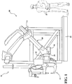
- Rivet setting system 10 may include an self-piercing rivet gun 12 operably connected to a programmable robot 14 for manipulating and controlling operation of rivet gun 12 for installation of rivets along an assembly line, for example a vehicle assembly line (not shown).
- Rivet gun 12 may include various configurations suitable for a particular application as known by those skilled in the art.
- robot 14 is suspended from a scaffolding structure 18. Further details of the scaffolding structure are included in U.S. Patent No. 8,201,723 assigned to the assignee of the present invention. Structure 18 supports robot 14 articulating arm 20 including a wrist 28 attached to arm 20 and configured for enabling motion in multiple degrees of freedom.
- a drive mechanism 30 may be employed for selectively controlling operation wrist 28.
- Drive mechanism 30 may include one or more servo motors and other control devices.
- Rivet gun 12 may be attached to robot 14 by releasably engaging a connector face plate 32 attached to wrist 28 with a connector plate 33 on rivet setting device 16. Other robot and configurations and orientations to support and manipulate rivet gun 12 may be used as known by those skilled in the art. Other connection or mounting structures and methods between the rivet gun 12 and robot 14 known by those skilled in the art may be used.
- rivet gun 12 may include a generally C-shaped frame 34 attached to connector plate 33 of rivet gun 16.
- a rivet die 36 may be mounted to one end 38 (a lower end in the illustrated exemplary configuration) of C-shaped frame 34.
- a rivet punch 40 may be mounted to an opposite end 42 (an upper end in the illustrated exemplary configuration) of C-shaped frame 34.
- Rivet punch 40 is positioned opposite rivet die 36 to enable rivet punch 40 to sequentially move in and out of contact with rivet die 36.
- a rivet punch drive mechanism 44 may be employed for forcibly moving rivet punch 40 toward and away from rivet die 36.
- Rivet drive mechanism 44 may include an electric drive motor, or another suitable drive mechanism, for apply an actuating force to rivet punch 40 to forcibly press a self-piercing rivet 46 held in rivet punch 40 into rivet die 36. Rivet drive mechanism 44 may also be used to retract rivet punch 40, for example, by reversing operation of the drive mechanism. Other configurations and operation of rivet gun 12 suitable for the particular assembly operation known by those skilled in the art may be used.
- a self-piercing rivet 46 generally includes a large diameter head 48 attached to a hollow shank 50 extending downward from the head. Rivet 46 is generally configured to be rotationally symmetrical. Shank 50 may include a central hollow cavity 52 that may be configured as a blind hole. A distal end 54 of shank 50 may include a beveled cutting edge 56. Other rivet structures and configurations known by those skilled in the art may be used.
- FIG. 3 illustrates an exemplary process of using self-piercing rivet 46 driven by rivet punch 40 to mechanically join two panels 58 and 60 to form workpiece 11.
- rivet 46 may also be used to connect a different number of sheets.
- Panels 58 and 60 may be relatively thin sheet materials, for example sheet steel or aluminum.
- the two panels 58 and 60 may be connected with rivet 46 by using punch 40 to apply a driving force to rivet head 48, which drives rivet 46 into the sheet metal panels.
- Distal end 54 of rivet 46 is sufficiently sharp to pierce the stacked sheet metal panels when subjected to the driving force applied by punch 40 acting on rivet head 48 to mechanically interlock the two sheets.
- Shank 50 of rivet 46 typically pierces punch side sheet 58, but generally does not pierce bottom die side sheet 60.
- Die 36 includes a cavity 62 for receiving portions of the fastened sheet metal panels 58 and 60 forced outward by shank 50 of rivet 46 driven in by punch 40.
- Shank 50 and the material of bottom die side sheet 60 immediately adjacent distal end 54 of shank 50 are deformed through the action of die 36 in order to mechanically interlock the two sheets 58 and 60.
- the exact configuration of die 36 will depend, at least in part, upon the shape of a button that is to be formed.
- examples of a rivet tape feeder 64 may be employed for sequentially delivering single rivets 46 to rivet gun 12.
- Rivet feeder 64 may utilize an elongated flexible rivet carrier tape 66 for transporting rivets 46 from a rivet storage reel 68 to rivet gun 12.
- the example reel 68 is shown in a horizontal orientation in Figure 4 and a vertical orientation in Figures 5A-B .
- Other forms of fastener or rivet reels 68 and their orientation to robot 14 and rivet gun 12 known by those skilled in the art may be used.
- rivet carrier tape 66 may be made from an extruded polymer or elastomer material and includes a web 70 interconnecting parallel side flanges 72 and 74 arranged on opposite sides of web 70.
- Rivet carrier tape 66 may include a plurality of equally spaced apart apertures 76 arranged along a length of the tape for receiving and removably securing rivets 46. Apertures 76 may be undersize relative to a diameter of shank 50 of rivet 46 to securely retain rivets 46 on rivet carrier tape 66 prior to be installed into workpiece 11.
- Punch 40 may be sequentially actuated to drive each rivet 46 from rivet carrier tape 66 and into workpiece 11.
- Rivet feeder 64 may be employed to feed rivet carrier tape 66 through rivet setting device 16 so that each rivet 46 becomes aligned with a path of punch 40 and is inserted by the punch into workpiece 11.
- Rivet carrier tape 66 may include drive apertures 78 positioned along the sides of web 70 adjacent side flanges 72 and 74. Drive apertures 78 may be engaged by pins on one or more drive sprockets (not shown) for feeding rivet carrier tape 66 into rivet setting device 16.
- Punch 40 may be actuated to sequentially drive each rivet 46 from rivet carrier tape 66 and insert the rivet into workpiece 11.
- Rivet feeder 64 may include an indexing mechanism (not shown) for sequentially feeding individual rivets 46 through rivet setting device 16.
- the exemplary storage reels 68 may be configured generally as a spool and rotatably mounted to a shaft 80. Rivet carrier tape 66 dispensed from storage reel 68 may pass through a conduit 82 for guiding the rivet carrier tape into rivet setting device 16. Rivet feeder 64 may employ a top feed, as illustrated in FIG. 5A , and a bottom feed, as illustrated in FIG. 5B . Storage reels 68 may be rotated in a counterclockwise (as viewed from a perspective of FIG.
- storage container 68 may be rotated in a clockwise direction (as viewed from a perspective of FIG. 5B ) to dispense rivet carrier tape 66 when employing the bottom feed arrangement.
- rivet feeder 86 includes primary or first rivet supply reel 88 and a backup or second rivet supply reel 90.
- Primary reel 88 and backup or secondary reel 90 may be similarly configured as rivet storage reel 68 as previously described.
- each of the primary 88 and secondary 90 reels are stocked or wound with a supply of rivets 46 attached to rivet carrier tape 66.
- hundreds or over a thousand rivets may be initially stored on each reel for selected delivery to rivet setting device 16 to support a high-volume production build.
- each of the primary 88 and secondary 90 reels are mounted on a reel carrier (not shown) in a front-to-back orientation as generally shown in Figures 7-9 .
- a primary rivet tape 89 carrying rivets 46 is aligned for feeding rivets to rivet gun 12 through selected movement of the tape by a driving devices as previously described.
- Secondary reel 90 is also positioned in general alignment for feeding a separate, secondary rivet tape 91 carrying rivets 46 to rivet gun 12 when the primary reel rivet supply is exhausted in the manner described below. It is understood that the position and orientation of the primary 88 and second reels 90 may vary from the illustrated position depending on the packaging space available and the feed system used by the particular rivet gun 12 as known by those skilled in the art. Although two reels are shown, it is contemplated that more than two reels may be used depending on the assembly operation and fasteners that are required.
- the example rivet setting system 10 includes a rivet carrier tape escapement or merging device 92 to guide and selectively link the first rivet tape 89 to the second rivet tape 91 for continuous supply of fasteners, preferably self-piercing rivets, to rivet gun 12.
- a rivet carrier tape escapement or merging device 92 to guide and selectively link the first rivet tape 89 to the second rivet tape 91 for continuous supply of fasteners, preferably self-piercing rivets, to rivet gun 12.
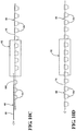
- both of the first or primary rivet tape 89 and backup or secondary rivet tape 91 enter a first end in preferably longitudinal alignment, the first tape 89 positioned directly above the second tape 91 with a vertical space between the tapes as generally shown in Figure 10A .
- rivets are selectively taken from primary reel 88 through advancement of first tape 89 through the escapement device 92 as previously described.
- a lead section 96 of second rivet carrier tape 91 lies idle and does not advance toward the rivet gun 12.
- lead section 96 of the second tape 91 does not include rivets 46 in several of the apertures 76 as generally shown in Figure 6A (left side).
- a tail section 104 of the first tape 89 enters the escapement device first end 110.
- the tail end includes several rivets 46 with the respective shanks extending downward in a direction toward the lead end of the second tape 91 positioned generally below the first tape as generally shown.
- escapement device 92 includes a tape joining mechanism 120 which operates to selectively position lead section 96 of second tape 91 into engaging position with the tail section 104 of first tape 89 prior to the tail section 104 passing completely through the escapement device 92.
- tape joining device 120 can include a plate, rail or other component that supports and assists in alignment of second tape 91 in the position shown and described in Figure 10A .
- joining device 120 may forcibly raise second tape 91 into contact with the protruding rivets 46 extending downward from the first tape 89 wherein the shanks 50 of one or more rivets 46 in the tail end 104 of the first tape engage respective apertures 76 in the second tape 91 to interlock the first 89 and second 91 tapes together such that the second tape 91 begins to advance toward rivet gun 12.
- tape joining device may be a pneumatically operated lift or servo motor operated device connected to a lower portion of the escapement device.
- the elevated first tape 89 may be forcibly moved downward toward the second tape 91 positioned below in a similar manner.
- dual devices may simultaneously operate to lower the first tape 89 and raise the second tape 91 into engagement to "pinch" the two tapes into engagement.
- Other tape joining schemes for example features on the tape substrate itself which may engage or interlock the tapes together, for example integrated hooks or catches molded into the tapes, known by those skilled in the art may be used. Further, alternate tape joining devices which physically move and position the tapes together known by those skilled in the art may be used.
- the second rivet reel 90 this is operable to provide a full stock of rivets to the rivet gun 12.
- the robot would have to be idled and the rivet reel replaced requiring manual intervention and a loss of valuable manufacturing time.
- much effort and time is spent on conventional devices attempting to track when a single reel or other rivet storage device would run empty.
- conventional reels and cartridges would just be replaced before the fasteners were depleted which wastes the rivets.
- one or more sensors 84, 86 may be used to monitor or detect the presence or absence of rivets or the movement of one or both of the reels 88 and 90.
- a sensor 98 may be employed to detect the presence of rivets 46 on the first tape 89 received from primary spool 88.
- sensor 98 may transmit a signal to a controller indicating that primary spool 88 is exhausted, or about to be exhausted, of rivets 46.
- the controller may then activate tape joining mechanism 120 in response to the signal received from sensor 98, instructing tape joining mechanism 120 to move lead section 96 of second tape 91 received from backup reel 90 into engagement with rivet carrier tape 66 received from primary spool 88, as illustrated, for example, in FIG 10B .
- Alternate or additional sensors for example vision systems, and other sensors and/or detectors, which are capable of providing electronic and/or visual notices or indicators to plant personnel of one or more conditions may be used as known by those skilled in the art.
- an alternate or additional sensor 84 may be mounted to one or more of the primary 88 and second 90 reels which detects movement or stoppage of movement of the reels, for example when the primary 88 is depleted of rivets and stops rotating and/or the second reel 90 begins rotation signaling that the first reel 88 has been depleted and the rivet gun device is now operating on the second reel of rivets.
- the controller may be configured to send an electronic and/or visual signal to notify an equipment operator or maintenance personnel that primary reel 88 is exhausted of rivets 46 and should be replaced.
- This provides the assembly plant significantly more time to replace the now depleted primary reel 88 providing for a continuous supply of rivets to the rivet gun 12 and greatly simplifies and improves the manual operations associated with the often hundreds of fastener robots that are deployed in large, high-volume vehicle assembly plants.
- the rivet reel support rack may include features to easily and quickly remove a depleted reel with a fully-stocked reel.
- the reel rack may also allow for the now feeding second reel 90 to be moved into the position of the depleted first reel which has been removed while the second reel 90 continues to feed rivets to the rivet gun 12. In the example where the rivet shanks are used to engage the tapes, this may be necessary to ensure that the lower or second reel 90 having a leading end with empty apertures 76 is positioned below the feeding reel so as to interlock the tapes as described above.
- the second reel can remain in its original position and the rivet joining device 120 is adjusted to take into account that the lower reel is now feeding so as to forcibly push the leading edge of the upper tape into engagement with the lower feeding tape when the lower tape is almost depleted.
Landscapes
- Engineering & Computer Science (AREA)
- Mechanical Engineering (AREA)
- Automatic Assembly (AREA)
- Insertion Pins And Rivets (AREA)
Priority Applications (1)
| Application Number | Priority Date | Filing Date | Title |
|---|---|---|---|
| PL14749030T PL2953772T3 (pl) | 2013-02-05 | 2014-02-05 | Aparat do ciągłego podawania elementów złącznych i sposób |
Applications Claiming Priority (2)
| Application Number | Priority Date | Filing Date | Title |
|---|---|---|---|
| US201361761050P | 2013-02-05 | 2013-02-05 | |
| PCT/US2014/014873 WO2014124007A1 (en) | 2013-02-05 | 2014-02-05 | Continuous fastener feeding apparatus and method |
Publications (3)
| Publication Number | Publication Date |
|---|---|
| EP2953772A1 EP2953772A1 (en) | 2015-12-16 |
| EP2953772A4 EP2953772A4 (en) | 2016-10-19 |
| EP2953772B1 true EP2953772B1 (en) | 2018-09-26 |
Family
ID=51258495
Family Applications (1)
| Application Number | Title | Priority Date | Filing Date |
|---|---|---|---|
| EP14749030.4A Not-in-force EP2953772B1 (en) | 2013-02-05 | 2014-02-05 | Continuous fastener feeding apparatus and method |
Country Status (5)
| Country | Link |
|---|---|
| US (2) | US9808857B2 (pl) |
| EP (1) | EP2953772B1 (pl) |
| ES (1) | ES2702882T3 (pl) |
| PL (1) | PL2953772T3 (pl) |
| WO (1) | WO2014124007A1 (pl) |
Families Citing this family (9)
| Publication number | Priority date | Publication date | Assignee | Title |
|---|---|---|---|---|
| US20170282238A1 (en) * | 2016-04-04 | 2017-10-05 | Whitesell Formed Components, Inc. | Fastener feed apparatus |
| IT201600083517A1 (it) * | 2016-08-08 | 2018-02-08 | Cosberg Spa | Linea di un impianto di produzione per l’assemblaggio di articoli multicomponente |
| GB201705753D0 (en) * | 2017-04-10 | 2017-05-24 | Henrob Ltd | Tape joining |
| US10758966B2 (en) | 2018-02-21 | 2020-09-01 | Newfrey Llc | Processor-controlled tape feed apparatus and method for a self-piercing rivet machine |
| US10456826B2 (en) | 2018-02-21 | 2019-10-29 | Newfrey Llc | Tape feed apparatus and method for a self-piercing rivet machine |
| US10780489B2 (en) | 2018-02-21 | 2020-09-22 | Newfrey Llc | Tool-free opening tape feed receiver for a self-piercing rivet machine |
| US10654093B2 (en) * | 2018-07-10 | 2020-05-19 | Electroimpact, Inc. | Riveting apparatus with moveable nose portion to match an adjoining rivet feed track |
| FR3112092B1 (fr) * | 2020-07-03 | 2023-01-13 | Gys | Outil de poinconnage d’une tole ou d’un assemblage multi-couches de toles et procede de poinconnage correspondant. |
| CN114101569B (zh) * | 2021-11-12 | 2024-05-03 | 苏州施米特机械有限公司 | 一种自冲铆接设备收料机构及自冲铆接设备 |
Family Cites Families (65)
| Publication number | Priority date | Publication date | Assignee | Title |
|---|---|---|---|---|
| US3189293A (en) * | 1962-04-30 | 1965-06-15 | Beloit Eastern Corp | Radial flying splice mechanism |
| US3208657A (en) | 1963-03-18 | 1965-09-28 | Cohn Maurice | Tape tensioning and feeding mechanism for a fastener applying machine |
| US3212632A (en) * | 1963-10-03 | 1965-10-19 | Fastener Corp | Fastener assemblage |
| US3589957A (en) | 1969-01-23 | 1971-06-29 | Maurice Cohn | Method of applying fastener devices to a tape |
| US3769124A (en) * | 1972-03-21 | 1973-10-30 | Mobil Oil Corp | Method and apparatus for splicing foam sheet material |
| US4004683A (en) * | 1975-05-07 | 1977-01-25 | Omark Industries, Inc. | Packaging for power loads |
| NZ196400A (en) * | 1980-03-10 | 1984-03-16 | Furma Mfg Co Pty Ltd | Sequential unit feeding apparatus |
| JPS5951810B2 (ja) * | 1980-09-25 | 1984-12-15 | ワイケイケイ株式会社 | スライドフアスナ−ストリンガ−の組合せ方法及びその装置 |
| US4673142A (en) * | 1983-11-28 | 1987-06-16 | Enkel Corporation | Apparatus for continuously supplying a web of sheet material |
| DE3613096A1 (de) | 1986-04-18 | 1987-10-29 | Messer Griesheim Gmbh | Verfahren zum bearbeiten von werkstuecken |
| US4842681A (en) * | 1987-03-30 | 1989-06-27 | Bader B Robert | Splicing method and apparatus for sheet materials |
| JPH0512195Y2 (pl) * | 1987-03-31 | 1993-03-29 | ||
| NL8702407A (nl) * | 1987-10-09 | 1989-05-01 | Stork Contiweb | Inrichting voor het continu vanaf een voorraadrol toevoeren van een materiaalbaan. |
| GB9114953D0 (en) * | 1991-07-11 | 1991-08-28 | Henrob Ltd | A portable riveting machine and a rivet supply therefor |
| JP2536334B2 (ja) | 1991-07-24 | 1996-09-18 | 日本鋼管株式会社 | パイプの円周溶接方法 |
| US5189514A (en) | 1991-08-29 | 1993-02-23 | General Dynamics Corporation Convair Division | Guidance system for automatic riveters |
| US5253819A (en) * | 1991-09-04 | 1993-10-19 | Butler Automatic, Inc. | Speed match splicing method and apparatus |
| US5136873A (en) * | 1991-11-13 | 1992-08-11 | S.A.R.G. Research Assoc, Ltd. | Automatic blind rivet setting device |
| US5333803A (en) * | 1992-12-22 | 1994-08-02 | Mirek Planeta | Strip unwinding machine |
| US5762284A (en) * | 1993-02-19 | 1998-06-09 | Valmet Corporation | Assembly for the unwinder end of an off-machine paper web handling line |
| US5339983A (en) | 1993-05-18 | 1994-08-23 | Multifastener Corporation | Dual pawl spool feeder |
| JPH0780645A (ja) | 1993-09-08 | 1995-03-28 | Fanuc Ltd | 溶接センサの冷却装置 |
| JPH07116849A (ja) | 1993-10-26 | 1995-05-09 | Fanuc Ltd | 光軸調整手段を有した溶接センサ |
| JPH07129217A (ja) | 1993-10-29 | 1995-05-19 | Fanuc Ltd | レーザセンサを用いたロボット制御方法 |
| CA2169763C (en) * | 1994-06-16 | 2001-04-10 | Jorma Kinnunen | Splicing device for a continuous unwind stand |
| US5481085A (en) | 1994-09-09 | 1996-01-02 | University Of Kentucky Research Foundation | Apparatus and method for measuring 3-D weld pool shape |
| US5741096A (en) | 1995-11-30 | 1998-04-21 | The Boeing Company | Line-laser assisted alignment apparatus |
| US5691815A (en) | 1996-01-02 | 1997-11-25 | Lockheed Missiles & Space Co., Inc. | Laser inspection tool system |
| US6276050B1 (en) | 1998-07-20 | 2001-08-21 | Emhart Inc. | Riveting system and process for forming a riveted joint |
| US5931298A (en) * | 1998-02-04 | 1999-08-03 | Huang; Shih Chang | Strip for supporting nails |
| US6164489A (en) | 1998-03-25 | 2000-12-26 | Fabristeel Products, Inc. | Carousel feed |
| US6051095A (en) * | 1998-07-20 | 2000-04-18 | C.G. Bretting Manufacturing Company, Inc. | Flying web splice apparatus and method |
| GB9816472D0 (en) | 1998-07-30 | 1998-09-23 | Ariel Ind Plc | Multiple fastener application system |
| DE19903020A1 (de) * | 1999-01-26 | 2000-08-03 | Honsel M H Beteiligungs Gmbh | Nietsetzgerät |
| DE19930087C5 (de) | 1999-06-30 | 2011-12-01 | Inos Automationssoftware Gmbh | Verfahren und Vorrichtung zur Regelung der Vorhalteposition eines Manipulators eines Handhabungsgeräts |
| FI114907B (fi) * | 2000-02-15 | 2005-01-31 | Metso Paper Inc | Menetelmä ja laitteisto aukirullauksessa |
| US7423734B1 (en) | 2000-04-25 | 2008-09-09 | Ilmar Luik | Combined video camera and toolholder with triangulation sensing |
| IT1318105B1 (it) * | 2000-07-05 | 2003-07-23 | Giovanni Gambini | Dispositivo per la giunzione di un lembo finale di una bobina di carta in esaurimento con il lembo iniziale di una nuova bobina. |
| US6792987B2 (en) * | 2000-07-06 | 2004-09-21 | Paktech, Inc. | Automatic label splicing apparatus |
| US6893528B2 (en) * | 2000-11-01 | 2005-05-17 | Adalis Corporation | Web material advance system for web material applicator |
| JP3424001B2 (ja) | 2000-12-28 | 2003-07-07 | 川崎重工業株式会社 | レーザ溶接方法およびレーザ溶接装置 |
| JP4195206B2 (ja) | 2001-04-04 | 2008-12-10 | 株式会社日立製作所 | 摩擦攪拌接合装置 |
| PT1448334E (pt) | 2001-11-15 | 2011-06-28 | Precitec Vision Gmbh & Co Kg | Processo e dispositivo para detetar a qualidade de uma costura de soldadura durante a soldadura de peças de trabalho |
| SE521787C2 (sv) | 2002-04-05 | 2003-12-09 | Volvo Aero Corp | Anordning och förfarande för kontroll av ett svetsområde, inrättning och förfarande för styrning av en svetsoperation, datorprogram och datorprogramprodukt |
| SE0302092L (sv) | 2003-07-11 | 2005-01-12 | Abb Ab | Robotsystem |
| ITFI20040016A1 (it) * | 2004-01-21 | 2004-04-21 | Perini Fabio Spa | Dispositivo svolgitore per bobine di materiale nastriforme e relativo metodo |
| JP4570893B2 (ja) * | 2004-03-31 | 2010-10-27 | 日本パワーファスニング株式会社 | 携帯式ファスナー打ち込み工具 |
| JP2005288608A (ja) * | 2004-03-31 | 2005-10-20 | Jpf Works Kk | 携帯式ファスナー打ち込み工具 |
| CA2463409A1 (en) | 2004-04-02 | 2005-10-02 | Servo-Robot Inc. | Intelligent laser joining head |
| ITFI20040108A1 (it) * | 2004-05-07 | 2004-08-07 | Perini Fabio Spa | Dispositivo svolgitore multiforme |
| AT502283B1 (de) | 2005-07-15 | 2007-05-15 | Fronius Int Gmbh | Schweissverfahren und schweisssystem mit bestimmung der position des schweissbrenners |
| DE102005000157B3 (de) * | 2005-11-16 | 2007-04-05 | Hilti Ag | Befestigungsmittel-Zuführeinrichtung für ein handgeführtes kraftbetriebenes Eintreibgerät |
| EP2062841B1 (en) * | 2007-11-23 | 2013-02-13 | Goss Contiweb B.V. | Device for applying a paper web onto a paper reel and corresponding reel changer |
| DE102008040140A1 (de) | 2008-07-03 | 2010-01-07 | Robert Bosch Gmbh | Kolbenpumpe |
| KR102021611B1 (ko) * | 2008-11-28 | 2019-09-16 | 에이씨에스 인더스트리즈, 인크. | 와이어 메시 리벳 |
| US8552337B2 (en) | 2009-06-11 | 2013-10-08 | Illinois Tool Works Inc. | Weld defect detection systems and methods for laser hybrid welding |
| US20100326962A1 (en) | 2009-06-24 | 2010-12-30 | General Electric Company | Welding control system |
| DE102009042986B3 (de) | 2009-09-25 | 2011-03-03 | Precitec Kg | Schweißkopf und Verfahren zum Fügen eines Werkstücks |
| DE102009058817A1 (de) | 2009-12-18 | 2010-08-05 | Daimler Ag | Anlage und Verfahren zum maßhaltigen Rollfalzen eines Bauteils |
| DE102010011253B4 (de) | 2010-03-12 | 2013-07-11 | Precitec Kg | Laserbearbeitungskopf, Robotervorrichtung und Verfahren zur Bearbeitung eines Werkstücks mittels eines Laserstrahls |
| US20110284508A1 (en) | 2010-05-21 | 2011-11-24 | Kabushiki Kaisha Toshiba | Welding system and welding method |
| US20130001116A1 (en) * | 2011-06-28 | 2013-01-03 | Sheng-Huei Lin | Nail belt having mating member and corresponding mating member at both ends respectively |
| US9370819B2 (en) | 2012-04-02 | 2016-06-21 | The Boeing Company | Collar installation end effector |
| US20150101175A1 (en) | 2012-04-13 | 2015-04-16 | Ryerson University | Automated percussive riveting system |
| US20160175976A1 (en) | 2014-12-18 | 2016-06-23 | Illinois Tool Works Inc. | Systems and methods for determining a weld torch location |
-
2014
- 2014-02-05 US US14/173,298 patent/US9808857B2/en not_active Expired - Fee Related
- 2014-02-05 PL PL14749030T patent/PL2953772T3/pl unknown
- 2014-02-05 ES ES14749030T patent/ES2702882T3/es active Active
- 2014-02-05 WO PCT/US2014/014873 patent/WO2014124007A1/en not_active Ceased
- 2014-02-05 EP EP14749030.4A patent/EP2953772B1/en not_active Not-in-force
-
2017
- 2017-08-28 US US15/688,064 patent/US9962758B2/en active Active
Non-Patent Citations (1)
| Title |
|---|
| None * |
Also Published As
| Publication number | Publication date |
|---|---|
| ES2702882T3 (es) | 2019-03-06 |
| US9808857B2 (en) | 2017-11-07 |
| EP2953772A4 (en) | 2016-10-19 |
| US9962758B2 (en) | 2018-05-08 |
| PL2953772T3 (pl) | 2019-03-29 |
| EP2953772A1 (en) | 2015-12-16 |
| WO2014124007A1 (en) | 2014-08-14 |
| US20170355013A1 (en) | 2017-12-14 |
| US20140217227A1 (en) | 2014-08-07 |
Similar Documents
| Publication | Publication Date | Title |
|---|---|---|
| US9962758B2 (en) | Continuous fastener feeding apparatus and method | |
| US12472589B2 (en) | System and method with floating welder for high rate production welding | |
| JP4494372B2 (ja) | 固定装置に関する改良 | |
| JP3394773B2 (ja) | 固定用ツール及びそのためのテープ | |
| US7748097B1 (en) | Fastener insertion apparatus | |
| JP6102925B2 (ja) | 接合要素を給送するための方法及び装置 | |
| EP3069807B1 (en) | Drilling machine and method of manufacturing drilled product | |
| US6796454B1 (en) | Fastening machines | |
| EP3609635B1 (en) | Rivet tape joining clip |
Legal Events
| Date | Code | Title | Description |
|---|---|---|---|
| PUAI | Public reference made under article 153(3) epc to a published international application that has entered the european phase |
Free format text: ORIGINAL CODE: 0009012 |
|
| 17P | Request for examination filed |
Effective date: 20150730 |
|
| AK | Designated contracting states |
Kind code of ref document: A1 Designated state(s): AL AT BE BG CH CY CZ DE DK EE ES FI FR GB GR HR HU IE IS IT LI LT LU LV MC MK MT NL NO PL PT RO RS SE SI SK SM TR |
|
| AX | Request for extension of the european patent |
Extension state: BA ME |
|
| DAX | Request for extension of the european patent (deleted) | ||
| REG | Reference to a national code |
Ref country code: DE Ref legal event code: R079 Ref document number: 602014033018 Country of ref document: DE Free format text: PREVIOUS MAIN CLASS: B27F0007000000 Ipc: B21J0015320000 |
|
| A4 | Supplementary search report drawn up and despatched |
Effective date: 20160915 |
|
| RIC1 | Information provided on ipc code assigned before grant |
Ipc: B21J 15/32 20060101AFI20160909BHEP |
|
| GRAP | Despatch of communication of intention to grant a patent |
Free format text: ORIGINAL CODE: EPIDOSNIGR1 |
|
| STAA | Information on the status of an ep patent application or granted ep patent |
Free format text: STATUS: GRANT OF PATENT IS INTENDED |
|
| INTG | Intention to grant announced |
Effective date: 20180321 |
|
| GRAS | Grant fee paid |
Free format text: ORIGINAL CODE: EPIDOSNIGR3 |
|
| GRAJ | Information related to disapproval of communication of intention to grant by the applicant or resumption of examination proceedings by the epo deleted |
Free format text: ORIGINAL CODE: EPIDOSDIGR1 |
|
| GRAL | Information related to payment of fee for publishing/printing deleted |
Free format text: ORIGINAL CODE: EPIDOSDIGR3 |
|
| STAA | Information on the status of an ep patent application or granted ep patent |
Free format text: STATUS: REQUEST FOR EXAMINATION WAS MADE |
|
| GRAR | Information related to intention to grant a patent recorded |
Free format text: ORIGINAL CODE: EPIDOSNIGR71 |
|
| STAA | Information on the status of an ep patent application or granted ep patent |
Free format text: STATUS: GRANT OF PATENT IS INTENDED |
|
| INTC | Intention to grant announced (deleted) | ||
| GRAA | (expected) grant |
Free format text: ORIGINAL CODE: 0009210 |
|
| STAA | Information on the status of an ep patent application or granted ep patent |
Free format text: STATUS: THE PATENT HAS BEEN GRANTED |
|
| INTG | Intention to grant announced |
Effective date: 20180815 |
|
| AK | Designated contracting states |
Kind code of ref document: B1 Designated state(s): AL AT BE BG CH CY CZ DE DK EE ES FI FR GB GR HR HU IE IS IT LI LT LU LV MC MK MT NL NO PL PT RO RS SE SI SK SM TR |
|
| REG | Reference to a national code |
Ref country code: GB Ref legal event code: FG4D |
|
| REG | Reference to a national code |
Ref country code: CH Ref legal event code: EP |
|
| REG | Reference to a national code |
Ref country code: AT Ref legal event code: REF Ref document number: 1045388 Country of ref document: AT Kind code of ref document: T Effective date: 20181015 |
|
| REG | Reference to a national code |
Ref country code: IE Ref legal event code: FG4D |
|
| REG | Reference to a national code |
Ref country code: DE Ref legal event code: R096 Ref document number: 602014033018 Country of ref document: DE |
|
| REG | Reference to a national code |
Ref country code: NL Ref legal event code: MP Effective date: 20180926 |
|
| PG25 | Lapsed in a contracting state [announced via postgrant information from national office to epo] |
Ref country code: SE Free format text: LAPSE BECAUSE OF FAILURE TO SUBMIT A TRANSLATION OF THE DESCRIPTION OR TO PAY THE FEE WITHIN THE PRESCRIBED TIME-LIMIT Effective date: 20180926 Ref country code: BG Free format text: LAPSE BECAUSE OF FAILURE TO SUBMIT A TRANSLATION OF THE DESCRIPTION OR TO PAY THE FEE WITHIN THE PRESCRIBED TIME-LIMIT Effective date: 20181226 Ref country code: NO Free format text: LAPSE BECAUSE OF FAILURE TO SUBMIT A TRANSLATION OF THE DESCRIPTION OR TO PAY THE FEE WITHIN THE PRESCRIBED TIME-LIMIT Effective date: 20181226 Ref country code: LT Free format text: LAPSE BECAUSE OF FAILURE TO SUBMIT A TRANSLATION OF THE DESCRIPTION OR TO PAY THE FEE WITHIN THE PRESCRIBED TIME-LIMIT Effective date: 20180926 Ref country code: RS Free format text: LAPSE BECAUSE OF FAILURE TO SUBMIT A TRANSLATION OF THE DESCRIPTION OR TO PAY THE FEE WITHIN THE PRESCRIBED TIME-LIMIT Effective date: 20180926 Ref country code: GR Free format text: LAPSE BECAUSE OF FAILURE TO SUBMIT A TRANSLATION OF THE DESCRIPTION OR TO PAY THE FEE WITHIN THE PRESCRIBED TIME-LIMIT Effective date: 20181227 Ref country code: FI Free format text: LAPSE BECAUSE OF FAILURE TO SUBMIT A TRANSLATION OF THE DESCRIPTION OR TO PAY THE FEE WITHIN THE PRESCRIBED TIME-LIMIT Effective date: 20180926 |
|
| REG | Reference to a national code |
Ref country code: LT Ref legal event code: MG4D |
|
| PG25 | Lapsed in a contracting state [announced via postgrant information from national office to epo] |
Ref country code: LV Free format text: LAPSE BECAUSE OF FAILURE TO SUBMIT A TRANSLATION OF THE DESCRIPTION OR TO PAY THE FEE WITHIN THE PRESCRIBED TIME-LIMIT Effective date: 20180926 Ref country code: AL Free format text: LAPSE BECAUSE OF FAILURE TO SUBMIT A TRANSLATION OF THE DESCRIPTION OR TO PAY THE FEE WITHIN THE PRESCRIBED TIME-LIMIT Effective date: 20180926 Ref country code: HR Free format text: LAPSE BECAUSE OF FAILURE TO SUBMIT A TRANSLATION OF THE DESCRIPTION OR TO PAY THE FEE WITHIN THE PRESCRIBED TIME-LIMIT Effective date: 20180926 |
|
| REG | Reference to a national code |
Ref country code: ES Ref legal event code: FG2A Ref document number: 2702882 Country of ref document: ES Kind code of ref document: T3 Effective date: 20190306 |
|
| REG | Reference to a national code |
Ref country code: AT Ref legal event code: MK05 Ref document number: 1045388 Country of ref document: AT Kind code of ref document: T Effective date: 20180926 |
|
| PG25 | Lapsed in a contracting state [announced via postgrant information from national office to epo] |
Ref country code: IS Free format text: LAPSE BECAUSE OF FAILURE TO SUBMIT A TRANSLATION OF THE DESCRIPTION OR TO PAY THE FEE WITHIN THE PRESCRIBED TIME-LIMIT Effective date: 20190126 Ref country code: AT Free format text: LAPSE BECAUSE OF FAILURE TO SUBMIT A TRANSLATION OF THE DESCRIPTION OR TO PAY THE FEE WITHIN THE PRESCRIBED TIME-LIMIT Effective date: 20180926 Ref country code: EE Free format text: LAPSE BECAUSE OF FAILURE TO SUBMIT A TRANSLATION OF THE DESCRIPTION OR TO PAY THE FEE WITHIN THE PRESCRIBED TIME-LIMIT Effective date: 20180926 Ref country code: NL Free format text: LAPSE BECAUSE OF FAILURE TO SUBMIT A TRANSLATION OF THE DESCRIPTION OR TO PAY THE FEE WITHIN THE PRESCRIBED TIME-LIMIT Effective date: 20180926 Ref country code: CZ Free format text: LAPSE BECAUSE OF FAILURE TO SUBMIT A TRANSLATION OF THE DESCRIPTION OR TO PAY THE FEE WITHIN THE PRESCRIBED TIME-LIMIT Effective date: 20180926 Ref country code: RO Free format text: LAPSE BECAUSE OF FAILURE TO SUBMIT A TRANSLATION OF THE DESCRIPTION OR TO PAY THE FEE WITHIN THE PRESCRIBED TIME-LIMIT Effective date: 20180926 |
|
| PG25 | Lapsed in a contracting state [announced via postgrant information from national office to epo] |
Ref country code: PT Free format text: LAPSE BECAUSE OF FAILURE TO SUBMIT A TRANSLATION OF THE DESCRIPTION OR TO PAY THE FEE WITHIN THE PRESCRIBED TIME-LIMIT Effective date: 20190126 Ref country code: SM Free format text: LAPSE BECAUSE OF FAILURE TO SUBMIT A TRANSLATION OF THE DESCRIPTION OR TO PAY THE FEE WITHIN THE PRESCRIBED TIME-LIMIT Effective date: 20180926 Ref country code: SK Free format text: LAPSE BECAUSE OF FAILURE TO SUBMIT A TRANSLATION OF THE DESCRIPTION OR TO PAY THE FEE WITHIN THE PRESCRIBED TIME-LIMIT Effective date: 20180926 |
|
| REG | Reference to a national code |
Ref country code: DE Ref legal event code: R097 Ref document number: 602014033018 Country of ref document: DE |
|
| PG25 | Lapsed in a contracting state [announced via postgrant information from national office to epo] |
Ref country code: DK Free format text: LAPSE BECAUSE OF FAILURE TO SUBMIT A TRANSLATION OF THE DESCRIPTION OR TO PAY THE FEE WITHIN THE PRESCRIBED TIME-LIMIT Effective date: 20180926 |
|
| PLBE | No opposition filed within time limit |
Free format text: ORIGINAL CODE: 0009261 |
|
| STAA | Information on the status of an ep patent application or granted ep patent |
Free format text: STATUS: NO OPPOSITION FILED WITHIN TIME LIMIT |
|
| 26N | No opposition filed |
Effective date: 20190627 |
|
| REG | Reference to a national code |
Ref country code: CH Ref legal event code: PL |
|
| PG25 | Lapsed in a contracting state [announced via postgrant information from national office to epo] |
Ref country code: MC Free format text: LAPSE BECAUSE OF FAILURE TO SUBMIT A TRANSLATION OF THE DESCRIPTION OR TO PAY THE FEE WITHIN THE PRESCRIBED TIME-LIMIT Effective date: 20180926 Ref country code: LU Free format text: LAPSE BECAUSE OF NON-PAYMENT OF DUE FEES Effective date: 20190205 Ref country code: SI Free format text: LAPSE BECAUSE OF FAILURE TO SUBMIT A TRANSLATION OF THE DESCRIPTION OR TO PAY THE FEE WITHIN THE PRESCRIBED TIME-LIMIT Effective date: 20180926 |
|
| REG | Reference to a national code |
Ref country code: BE Ref legal event code: MM Effective date: 20190228 |
|
| REG | Reference to a national code |
Ref country code: IE Ref legal event code: MM4A |
|
| PG25 | Lapsed in a contracting state [announced via postgrant information from national office to epo] |
Ref country code: LI Free format text: LAPSE BECAUSE OF NON-PAYMENT OF DUE FEES Effective date: 20190228 Ref country code: CH Free format text: LAPSE BECAUSE OF NON-PAYMENT OF DUE FEES Effective date: 20190228 |
|
| PG25 | Lapsed in a contracting state [announced via postgrant information from national office to epo] |
Ref country code: IE Free format text: LAPSE BECAUSE OF NON-PAYMENT OF DUE FEES Effective date: 20190205 |
|
| PG25 | Lapsed in a contracting state [announced via postgrant information from national office to epo] |
Ref country code: BE Free format text: LAPSE BECAUSE OF NON-PAYMENT OF DUE FEES Effective date: 20190228 |
|
| PG25 | Lapsed in a contracting state [announced via postgrant information from national office to epo] |
Ref country code: TR Free format text: LAPSE BECAUSE OF FAILURE TO SUBMIT A TRANSLATION OF THE DESCRIPTION OR TO PAY THE FEE WITHIN THE PRESCRIBED TIME-LIMIT Effective date: 20180926 |
|
| PGFP | Annual fee paid to national office [announced via postgrant information from national office to epo] |
Ref country code: IT Payment date: 20200220 Year of fee payment: 7 Ref country code: GB Payment date: 20200227 Year of fee payment: 7 Ref country code: ES Payment date: 20200302 Year of fee payment: 7 Ref country code: DE Payment date: 20200227 Year of fee payment: 7 Ref country code: PL Payment date: 20200218 Year of fee payment: 7 |
|
| PG25 | Lapsed in a contracting state [announced via postgrant information from national office to epo] |
Ref country code: MT Free format text: LAPSE BECAUSE OF NON-PAYMENT OF DUE FEES Effective date: 20190205 |
|
| PGFP | Annual fee paid to national office [announced via postgrant information from national office to epo] |
Ref country code: FR Payment date: 20200225 Year of fee payment: 7 |
|
| PG25 | Lapsed in a contracting state [announced via postgrant information from national office to epo] |
Ref country code: CY Free format text: LAPSE BECAUSE OF FAILURE TO SUBMIT A TRANSLATION OF THE DESCRIPTION OR TO PAY THE FEE WITHIN THE PRESCRIBED TIME-LIMIT Effective date: 20180926 |
|
| PG25 | Lapsed in a contracting state [announced via postgrant information from national office to epo] |
Ref country code: HU Free format text: LAPSE BECAUSE OF FAILURE TO SUBMIT A TRANSLATION OF THE DESCRIPTION OR TO PAY THE FEE WITHIN THE PRESCRIBED TIME-LIMIT; INVALID AB INITIO Effective date: 20140205 |
|
| REG | Reference to a national code |
Ref country code: DE Ref legal event code: R119 Ref document number: 602014033018 Country of ref document: DE |
|
| GBPC | Gb: european patent ceased through non-payment of renewal fee |
Effective date: 20210205 |
|
| PG25 | Lapsed in a contracting state [announced via postgrant information from national office to epo] |
Ref country code: DE Free format text: LAPSE BECAUSE OF NON-PAYMENT OF DUE FEES Effective date: 20210901 Ref country code: FR Free format text: LAPSE BECAUSE OF NON-PAYMENT OF DUE FEES Effective date: 20210228 Ref country code: GB Free format text: LAPSE BECAUSE OF NON-PAYMENT OF DUE FEES Effective date: 20210205 |
|
| PG25 | Lapsed in a contracting state [announced via postgrant information from national office to epo] |
Ref country code: IT Free format text: LAPSE BECAUSE OF NON-PAYMENT OF DUE FEES Effective date: 20210205 |
|
| REG | Reference to a national code |
Ref country code: ES Ref legal event code: FD2A Effective date: 20220504 |
|
| PG25 | Lapsed in a contracting state [announced via postgrant information from national office to epo] |
Ref country code: MK Free format text: LAPSE BECAUSE OF FAILURE TO SUBMIT A TRANSLATION OF THE DESCRIPTION OR TO PAY THE FEE WITHIN THE PRESCRIBED TIME-LIMIT Effective date: 20180926 |
|
| PG25 | Lapsed in a contracting state [announced via postgrant information from national office to epo] |
Ref country code: ES Free format text: LAPSE BECAUSE OF NON-PAYMENT OF DUE FEES Effective date: 20210206 |
|
| PG25 | Lapsed in a contracting state [announced via postgrant information from national office to epo] |
Ref country code: PL Free format text: LAPSE BECAUSE OF NON-PAYMENT OF DUE FEES Effective date: 20210205 |