EP2953793B1 - Système de commande d'une presse à imprimer - Google Patents
Système de commande d'une presse à imprimer Download PDFInfo
- Publication number
- EP2953793B1 EP2953793B1 EP14704315.2A EP14704315A EP2953793B1 EP 2953793 B1 EP2953793 B1 EP 2953793B1 EP 14704315 A EP14704315 A EP 14704315A EP 2953793 B1 EP2953793 B1 EP 2953793B1
- Authority
- EP
- European Patent Office
- Prior art keywords
- printing press
- hand
- sensor
- control
- control station
- Prior art date
- Legal status (The legal status is an assumption and is not a legal conclusion. Google has not performed a legal analysis and makes no representation as to the accuracy of the status listed.)
- Active
Links
Images



Classifications
-
- B—PERFORMING OPERATIONS; TRANSPORTING
- B41—PRINTING; LINING MACHINES; TYPEWRITERS; STAMPS
- B41F—PRINTING MACHINES OR PRESSES
- B41F33/00—Indicating, counting, warning, control or safety devices
-
- B—PERFORMING OPERATIONS; TRANSPORTING
- B41—PRINTING; LINING MACHINES; TYPEWRITERS; STAMPS
- B41F—PRINTING MACHINES OR PRESSES
- B41F33/00—Indicating, counting, warning, control or safety devices
- B41F33/0009—Central control units
Definitions
- the invention relates to a system for printing machine operation according to the preamble of claim 1.
- a system for operating a printing press in particular a sheet-fed press, has a standard printing machine control station. There, relevant data for the operation of the printing press are entered and also visualized. It is connected to a plurality of control-side assemblies, which are arranged distributed in the printing press. So far, data can only be displayed in the area of the printing machine control station, which is why persons working on the printing machine, in particular printers or service personnel, always have to go to the area of the printing press control center for checking and correcting data.
- a printing machine control system connected to a printing machine control station of a printing press.
- the printing press in turn has a plurality of control-side assemblies, which are distributed in the printing press and assigned to different units of the printing press.
- At least one eyeglass-type display device is provided for control, which is wearable by a person working on a respective printing machine as spectacles, and which displays the person working on the printing machine data.
- the printing machine is provided with a printing machine control station and has a plurality of distributed in the printing machine arranged on the control side assemblies to aggregates of the printing press.
- the printing machine control system comprises at least one portable pointing device, by means of which a monitor of the printing press can be controlled and a pointing element shown there can be activated.
- An integrated operating concept has become known in printing presses.
- An apparatus for operating machines for processing substrates in the graphics industry is provided with at least one computer and at least one operating device with an input device and an output device.
- the device is characterized in that the computer is in communication with the input device and the output device and processes at least two signals from the group of acoustic, haptic or optical information.
- the acoustic information comes from microphones
- the haptic information comes from a wheel
- the optical information comes from a video camera.
- the operating device is provided with a screen for displaying a graphical user interface for controlling machine functions, with an operating device for inputting command-triggering operations for machine functions and for controlling functions of the graphical user interface.
- a control device is provided for converting input command-triggering operator actions into control commands for the machine functions and functions of the graphical user interface by the operator. This includes a device for inputting manual operator actions and a device for entering non-contact operator actions.
- the device for inputting non-contact operations comprises a sensor system for detecting non-contact actions of the operator, and a detection device for detecting a command-triggering operator action of the user detected by the sensor system non-contact actions of the operator.
- a gesture control for printing machines known.
- a control station with a screen for displaying Machine information provided.
- the control station is provided with a plurality of sensors for detecting gestures of an operator.
- a support for receiving sheets of printing material is arranged at the control station below a screen and at least one sensor detects gestures of the operator which are shown close to the surface of a printing material lying on the support.
- the sensors are designed as cameras and connected in the control station with a computer that evaluates images of the cameras such that movements of the eyes of the operator are detected and taken into account when displaying the machine information on the screen.
- gesture recognition as automatic recognition of gestures executed by humans by means of a computer is called.
- a branch of computer science deals with the algorithms and mathematical methods for the recognition of gestures and the use of gestures for human-computer interaction. Every posture and body movement can represent a gesture in principle. However, the greatest importance has the recognition of hand and head gestures.
- a variant of the gesture recognition is the detection of so-called mouse gestures.
- a movement can be understood with reference to the human-computer interaction.
- a static hand position can be understood. It can be distinguished between systems in which the sensor necessary for the detection is located directly on the body of the user, and those in which the user is observed by external sensors.
- Most on-body or hand-guided sensor systems use accelerometers or position sensors built into data gloves. The disadvantage of data glove-based systems is that the user must wear the glove to use the system.
- Hand-held systems such as game machine controllers can also be used for gesture input because they have acceleration sensors to detect the movement of the particular device.
- the gestures can be developed in an ergonomically restricted manner, since the assignment in the plane above a printed sheet on the contact surface of the control panel must always be taken into account. Furthermore, gesture detection by means of a camera detects and evaluates the operating action in a two-dimensional arrangement. It is therefore imperative that the operation takes place in clear two-dimensional identifiable gestures. This in turn is also ergonomically disadvantageous.
- touchscreens have the disadvantage that the display of help or explanatory texts by simply marking with a mouse pointer is not possible. Also, the so-called hovering, so the context-sensitive marking of active softbuttons for signaling a standby display in the screen display of a touchscreen monitor is not readily possible.
- large monitors have been used for some time to display information at control stations of printing presses. Switching the information coming to the large screen monitor for display is usually done by a large screen monitor associated with the mouse or corresponding input devices such as a touchpad). Another obvious option is to switch over to a corresponding user interface on one of the two touchscreens. The execution of the large monitor as a touch does not make sense, because the monitor is out of the reach of the user.
- the present invention is based on the problem to provide a novel system for printing press operation.
- a system for printing machine operation of a printing press with a printing machine control station and a plurality of printing presses arranged on the control side assemblies of the printing machine wherein at least one touch-free responsive three-dimensional detecting detection device provided on the printing machine control center and can be activated by an operator.
- data or control signals for the operation of the printing press can be generated via the printing machine control or the printing machine control center and transmitted to a large-screen monitor of the printing press control center.
- the receiving device is preferably designed as a 3D sensor for detecting hand and finger gestures.
- the detection device is used in the sphere of influence of the operating personnel for the printing machine control center to detect motions of an operating action on a large-screen monitor and to transmit them as control data.
- the detection device can have a device for activation / deactivation and / or identification of the operating personnel.
- the detection device is connected to transmit the control data determined and generated from the gesture by means of an interface with the printing machine and / or the printing press control and / or the printing machine control station.
- the detector may be portable to perform the operator actions.
- the detection device can be controlled by a service engineer to perform maintenance.
- the detection means may be associated with a safety controller to prevent unintentional generation of control signals to the printing press control station.
- the system for printing machine operation thus comprises at least one three-dimensionally detecting detection device as a 3D sensor.
- This detects gestural movements with respect to a picture content on a monitor, which is arranged manually unreachable in the printing press control center.
- a control action is carried out by means of a start gesture, from which follow-up actions can be initiated.
- the printing machine control station can be controlled by means of the detection device in such a way that contents imaged on the large-screen monitor can be changed by influencing the recording device in the representation or by means of non-contact selection of pointing elements.
- help information can be called up without accidental triggering of functions or unintentional inputs which are easily possible with a touch screen.
- the solution according to the invention further offers several advantages in ergonomic terms.
- the solution according to the invention is based on a gesture in three-dimensional assignment detecting device. This allows the operator to move his hands freely and is not forced to adapt this to a control surface or an operator panel. Also, as shown in a prior art solution, the operator does not have to constantly make sure that the gesture can also be constantly detected by a two-dimensionally imaging camera.
- a certain area can be marked and by one or several other gestures, for. the color level in this area will be changed.
- the operating personnel according to the invention generated by means of a detection device by gestures with one hand and their fingers or both hands and their fingers control signals that are used to control functions or for generating data by the person working on the printing press via a printing machine control center ,
- the working coordinate on the large-screen monitor is represented by a mark which is appropriately designed in size and contrast of the remote operating position.
- a kind of mouse pointer is displayed and moved on the large screen monitor by movements of the hand in front of or above the detection device.
- the representation takes place in the appropriate size as a hand cursor.
- the hand cursor may have the shape of a target.
- special actions of individual fingers can trigger specific actions or other interactions at just selected positions.
- the detection device reacts when a hand is held relatively quietly in front of or above the detection device for about one second in the detection area.
- the hand cursor is displayed in the center of the screen and can be subsequently moved in the X and Y direction by changing the direction in which the hand is pointing or by changing the hand position or other parameters on the screen.
- any number of additional parameters that influence certain operating characteristics can be visualized by means of special representations of the hand cursor.
- the hand curl (hand more or less open) could be used for a radius change of the circle around the hand cursor, thus making the positioning faster but coarser or slower but finer.
- the thumb can be moved relatively well independently of the other fingers. Therefore, with The thumb-specific actions are triggered according to mouse clicks. A quick drawing of the thumb on the index finger can correspond to such a mouse click. Furthermore, the detention of the mouse button can be imitated via a thumb held on the index finger. Therefore, drag-and-drop operations can be performed in a simple and intuitive way using the hold function.
- the hand of the operator can be kept relaxed and thus a fatigue-free operation for a long time is possible.
- the hand position is almost arbitrary and allows a safe operation from almost any position.
- the secure operation is realized by checking an initial condition, wherein the initial condition makes the hand cursor appear in the screen center, and then an evaluation of the relative movements of the hand or hands is performed.
- FIG. 1 shows a highly schematic representation of a trained as a sheet-fed press printing machine, according to.
- the printing machine comprises a feeder 10, four printing units 11, 12, 13 and 14 and a boom 15.
- the feeder 10, the printing units 11 to 14 and the boom 15 are each assigned at least one control-side subassembly 16, which are connected to a printing machine control station 17 and exchange data therewith.
- the printing machine control station 17 and the control-side assemblies 16 are components of a system for printing machine operation.
- the system for printing machine operation of the printing machine also includes at least one monitor 18.
- One or more monitors 18 are disposed on the printing machine control station 17 connected to the printing machine and are used by the operating persons for control, monitoring and data entry. Currently mostly so-called touch-screen monitors are used.
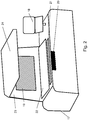
- FIG. 2 an enlarged perspective view of the printing machine control station 17 is shown. Substantial information about the operating state, machine data, process data and setting interfaces are made available to the person working on the printing press in the printing machine control station 17 on the monitors 18 and, if desired, by means of a large-screen monitor 19 in the form of a wall screen as a communication instrument.
- the large-screen monitor 19 is arranged on a rear wall 23 forming vertical surface of the printing machine control station 17. Above the rear wall 23, a lighting device 24 for positioned on the support surface 22 proof sheet from the printing machine is arranged. The print sheet is thus so on a support surface 22, which is arranged before the large-screen monitor 19 on the table of the printing machine control station 17 and behind an input keyboard 21 for operating a controller for a Farbzoneneingnagnagna the printing press.
- a three-dimensionally detecting 3D sensor 20 is therefore arranged to operate the printing machine control station 17 by means of the large-screen monitor 19 at a suitable location and in a preferred arrangement in the region of the front upper side of the printing machine control station 17.
- the 3D sensor 20 is accordingly designed with a suitable three-dimensionally detecting sensor system. Therefore, when movements such as those performed by the operator in the accommodation area of the 3D sensor 20 are detected, these movements are detected not only in their local assignment but also in position, direction, and movement behavior, and by the control of the 3D sensor 20 in one appropriate data form implemented.
- the 3D sensor 20 can have an approximately manually operable or near-sensor-sensitive additional detection device for switching off and on, in order to trigger or modify basic functions for operating the 3D sensor 20.
- the 3D sensor 20 can have an evaluation device, by means of which specific functions or specific groups of gestures or groups of gestures can be triggered, data can be selected or command levels can be controlled.
- the 3D sensor 20 is preferably used in its simplest embodiment and used without additional devices.
- the adaptation with regard to specific application cases takes place via its configuration in the operating environment.
- the movement data generated in the 3D sensor 20 can be used to control a mouse pointer or other type of display icon displayed on the monitor 18.
- each operator can operate the 3D sensor 20 without special measures.
- the operating personnel can then use the 3D sensor 20 to control printing data of the printing machine control station or of a color system or of any other assembly of the printing machine or of the system for printing machine operation.
- This provides information options, machine settings or function selection options that the printer normally has to make directly at the printing machine control station 17 via corresponding manual interfaces such as a mouse, keyboard or touchscreen monitor.
- the 3D sensor 20 via the interface motion data to the printing machine control station 17.
- the detected motion data are recorded and forwarded to the large screen monitor 19 for visualization.
- a function or selection option of the machine control or other systems of the printing press can then be selected and triggered directly via the 3D sensor 20.
- the 3D sensor 20 of the system for printing press operation can also z. B. be worn by a service technician, the 3D sensor 20 then allowed the service engineer to control service instructions for the printing press and thereby to make the appropriate selection actions on the monitor 18 and on the large screen monitor 19 on the printing machine control station 17.
- the control data to be transmitted can be sent wirelessly to the printing machine control station 17 or to a separate service computer, processed from from the desired data in the machine control or other systems of the printing press and optionally displayed or confirmed on the monitor 18.
- an operating area 25 is to be provided in front of the printing machine control station 17, from which the operating personnel are in the appropriate contact distance to the 3D sensor 20. From there, the operator's gestures can best be captured and evaluated. In addition, the visual access to the large screen monitor 19 is optimal in this area.
- FIG. 3 For this purpose, a lateral view is further shown, so that different arrangement options of the 3D sensor 20 are visible.
- the operator is in front of the printing machine control station 17 with support surface 22, rear wall 23, large screen monitor 19 and illumination device 24.
- the operator is facing the 3D sensor 20, wherein the 3D sensor 20 on the printing machine control center 19 of the support surface 22 in the region of the front edge and thus associated with the large screen monitor 19 on the rear wall 23 opposite.
- the hands of the operator are assigned to the detection range of the 3D sensor 20.
- FIG. 3 three mounting positions of the 3D sensor 20 are indicated in different line design. For each mounting position results in each case a different detection range 26, 27, 28 for the 3D sensor 20th For the approximately horizontal mounting position of the 3D sensor 20 in the plane of the support surface 22 results for the detection of movement substantially upwardly directed detection area 26th
- a detection range 26 results for the movement detection.
- the 3D sensor 20 can also be adjustably mounted in the printing press control station 17 in order to adapt it to changeable operating conditions.
- the 3D sensor 20 is configured to provide a large number of 3D parameters from the operator's hand and from the individual fingers in a rapid sequence of data sets. In addition, a series of basic gestures are recognized in a standardized way.
- the 3D sensor 20 delivers the mentioned parameters in rapid succession of data sets.
- the recognized hands and fingers receive identification tags in order to be able to assign them unambiguously, as long as they can be tracked by the 3D sensor 20. This makes it easy to evaluate from record to record the relative changes of each parameter.
- a finger can not be traced without gaps, its identification code disappears or it receives a new identification code.
- finger identification tags disappear, for example when two fingertips touch, and the same identification tags reappear when the fingertips move away from each other once the 3D sensor 20 has succeeded in plausible tracking. This could be exploited to identify a gripping gesture between thumb and forefinger.
- the evaluation of the 3D parameters determined and provided by the 3D sensor 20 takes place. From this, the system generates records for the detected movements during hand and / or finger and / or gesture recognition. In turn, on the large screen monitor 19, a mark is generated as a hand cursor 19 and the current monitor display is superimposed.
- FIG. 4 the operating situation of the 3D sensor 20 is shown schematically on the printing machine control station 17 and in conjunction with a large-screen monitor 19.
- a hand of the operator is arranged in the detection area 26 of the 3D sensor 20.
- the 3D sensor 20 can evaluate this gesture as a start operation for initiating an operation. This is reported to the large screen monitor 19 via the printing machine control station 17. Then appears on the large screen monitor 19 in the middle of the hand cursor 29.
- This is here formed in the manner of a crosshairs with the crosshairs surrounding rings.
- the hand cursor 29 is instantly recognizable and still easily visible.
- the hand cursor 29 can be guided over the image area of the large-screen monitor 19 by moving the hand detected by the 3D sensor 20 or its fingers.
- an image area 30 and an input area 31 are symbolically indicated. Which hand movement thereby triggers which movement of the hand cursor 29 can be freely defined in the configuration of the 3D sensor 20 and is dependent on ergonomic considerations.
- an image location or a picture element can be approached and marked by positioning the hand cursor 29 by triggering the marking action after the positioning by means of a finger movement, such as the thumb. Furthermore, entire image areas can be marked.
- the hand cursor 29 is set to an image location that is marked. Thereafter, the hand cursor 29 is pulled with the aid of a special finger movement, such as with a hand applied to the thumb, to a second image location, which is then also marked again and thus determines the marking area.
- this action can also be performed by detecting fingers of both hands. Furthermore, for turning over images or moving on to other views of the illustrated image system or to switch to other active applications, a wiping movement executable by the operator's hand in horizontal or vertical movement, actually moved transversely or longitudinally to the screen display on the large screen monitor 19 quickly becomes.
- the operation by means of the hand cursor 29 takes place in the input area 31 of the large screen monitor 19 according to further principles.
- the hand cursor 29 is guided over the input elements of the input area 31.
- Explanation and help texts can be displayed via an input field by means of the corresponding positioning.
- an input field can be displayed as active by discoloration.
- control options are diverse and far from exhausted with the described embodiments.
- the 3D sensor 20 To avoid incorrect inputs can be seen before that the 3D sensor 20 must first be armed by special gestures or a close operation. Likewise, it can be switched off correspondingly, and this can also be done automatically in the absence of gesture signals after an adjustable warning time.
- the system for printing machine operation can in particular also be designed such that the 3D sensor 20 is assigned a safety control by means of which an unintended generation and transmission of control signals to the printing machine control station 17 is prevented.
- this safety control can be carried out on the basis of a gesture analysis with respect to the standard supply of workable gestures.
- the input should preferably be executable at certain times and in certain operating conditions.
- the safety control can also be carried out on the basis of a check of the activation state, wherein an activation signal as a gesture or else directly to the 3D sensor 20 can be made necessary here, for example, for an input.
- the 3D sensor 20 can be tuned to the gestures of specific persons depending on the size and arm reach.
- the sensitization of the 3D sensor 20 on the basis of a coding by personal characteristics or by technical coding devices such as smart cards or USB devices can be done, which also serve to identify the operator on the printing machine control station 17. This ensures that safe operation can always take place.
- a selection option can be mapped around the 3D control instrument via a selection carousel. Similar would be possible Control the operation of pie menus (pie menu) by means of the 3D sensor 20.
- functional assignments to the hand cursor 29 and several existing activity buttons are specified context-sensitive in the respective action environment. Such an assignment may change for various applications in the printing press operation on display areas on the monitor.
- the context-sensitive background information for the image area 30 and the action area 31 in the representation of the large-screen monitor 19 in FIG. 4 different, as the possible actions are fundamentally different.
- the described functionalities in conjunction with the operating environment and derived from the respective movement data sets of the 3D sensor 29, can be integrated into each operating concept of a printing press and a printing press control station 17 and can be adapted in each case.
Landscapes
- User Interface Of Digital Computer (AREA)
Claims (10)
- Système d'utilisation d'une machine d'impression, en particulier d'une machine d'impression de feuilles, comportant un poste de directeur de machine d'impression (17) et plusieurs modules (16) disposés répartis dans la machine d'impression au niveau de la commande de la machine d'impression,
caractérisé par au moins un dispositif de détection à enregistrement tridimensionnel réagissant sans contact à des gestes (20) et qui est disposé au niveau du poste conducteur de machine d'impression (17) ou dans la zone de manoeuvre du poste conducteur de machine d'impression (17) et est activable par un geste par une personne travaillant sur la machine d'impression (17) et au moyen duquel des données ou des signaux de commande ou des actions d'information peuvent être générés et transmis au moyen d'un geste d'impression par une personne travaillant sur la machine d'impression par exécution des gestes par l'intermédiaire d'une interface en liaison avec un moniteur à grand écran (19) disposé au niveau du poste conducteur de machine d'impression (17),
dans lequel, en partant du dispositif de détection (20), des données ou des signaux de commande pour la manoeuvre de la machine d'impression peuvent être générés et transmis par la personne travaillant sur la machine d'impression par l'intermédiaire de la commande de la machine d'impression et/ou du poste conducteur de machine d'impression (17),
le dispositif d'enregistrement étant réalisé sous forme d'un capteur 3D (20) servant à détecter les gestes de la main et des doigts,
le dispositif de détection (20) étant associé à une zone de manoeuvre (25) en amont du poste conducteur de machine d'impression (17) et
le dispositif de détection (20) étant disposé de manière mobile au niveau du poste conducteur de machine d'impression (17). - Système d'utilisation de machine d'impression selon la revendication 1,
caractérisé en ce que
le dispositif de détection (20) présente un dispositif d'activation/de désactivation et/ou d'identification du personnel opérateur. - Système d'utilisation de machine d'impression selon les revendications 1 à 2,
caractérisé en ce que
le capteur 3D (20) est de type portable et que des données techniques d'impression et/ou fonctions pour le mode production ou le mode paramétrage de la machine d'impression peuvent être générées par une imprimante par l'intermédiaire de la commande de la machine d'impression et/ou du poste conducteur de la machine d'impression (17) et/ou d'un système de pupitre de couleur et/ou peuvent être sélectionnées et/ou déclenchées et/ou que des instructions d'entretien pour la maintenance de la machine d'impression peuvent être générées et/ou sélectionnées et/ou déclenchées par un monteur d'entretien au moyen du capteur 3D (20) par l'intermédiaire de la commande de la machine d'impression et/ou du poste conducteur de la machine d'impression (17). - Système d'utilisation de machine d'impression selon les revendications 1 à 3,
caractérisé en ce que
qu'est associée au dispositif de détection (20) une commande de sécurité au moyen de laquelle une génération non intentionnelle de signaux de commande en direction du poste conducteur de machine d'impression (17) est empêchée, le dispositif de commande étant réalisé sur la base d'une analyse des gestes, d'une analyse de l'état et de la période de fonctionnement ou sur la base d'un examen de l'état d'activation. - Système d'utilisation de machine d'impression selon les revendications 1 à 4,
caractérisé en ce que
le dispositif de détection (20) est conçu pour détecter un geste initial de l'utilisateur puis pour déclencher une initialisation d'une séquence d'utilisation en liaison avec le moniteur à grand écran (19), un élément de marquage ou de commande apparaissant sur le moniteur à grand écran (19) à la suite du geste initial. - Système d'utilisation de machine d'impression selon la revendication 5,
caractérisé en ce que
l'élément de marquage et de commande est réalisé sous forme d'un curseur en forme de main (29) à la manière d'une ligne de mire et s'affiche au milieu du moniteur à grand écran (19) en cas d'initialisation d'une séquence de manoeuvre. - Système d'utilisation de machine d'impression selon les revendications 1 à 6,
caractérisé en ce que,
pour positionner le curseur en forme de main (29) sur le moniteur à grand écran (19), les données du capteur 3D (20) sont exploitées en ce qui concerne la position, l'orientation et le mouvement de la main de l'utilisateur. - Système d'utilisation de machine d'impression selon les revendications 1 à 7,
caractérisé en ce que,
pour exécuter des actions en utilisant un positionnement du curseur en forme de main (29) sur le moniteur à grand écran (19), les données du capteur 3D (20) sont exploitées en ce qui concerne la position, l'orientation et le mouvement d'un, de plusieurs ou de tous les doigts. - Système d'utilisation de machine d'impression selon les revendications 1 à 8,
caractérisé en ce que
l'affichage du curseur en forme de main (29) sur le moniteur grand écran (19) est évalué grâce à des données du capteur 3D (20) en ce qui concerne la modification de la forme de la main de l'utilisateur. - Système d'utilisation de machine d'impression selon les revendications 1 à 9,
caractérisé en ce que
les conditions d'initialisation de la fonction du capteur 3D (20) sont paramétrées à un niveau plus élevé lors de l'initiation d'un cycle de manoeuvre au niveau de la détection des caractéristiques que les conditions d'arrêt.
Applications Claiming Priority (3)
| Application Number | Priority Date | Filing Date | Title |
|---|---|---|---|
| DE102013201979 | 2013-02-07 | ||
| DE102014101516 | 2014-02-06 | ||
| PCT/EP2014/052464 WO2014122280A1 (fr) | 2013-02-07 | 2014-02-07 | Système de commande d'une presse à imprimer |
Publications (2)
| Publication Number | Publication Date |
|---|---|
| EP2953793A1 EP2953793A1 (fr) | 2015-12-16 |
| EP2953793B1 true EP2953793B1 (fr) | 2017-11-08 |
Family
ID=50101878
Family Applications (1)
| Application Number | Title | Priority Date | Filing Date |
|---|---|---|---|
| EP14704315.2A Active EP2953793B1 (fr) | 2013-02-07 | 2014-02-07 | Système de commande d'une presse à imprimer |
Country Status (3)
| Country | Link |
|---|---|
| EP (1) | EP2953793B1 (fr) |
| DE (1) | DE102014101545A1 (fr) |
| WO (1) | WO2014122280A1 (fr) |
Families Citing this family (7)
| Publication number | Priority date | Publication date | Assignee | Title |
|---|---|---|---|---|
| DE102014000876B3 (de) | 2014-01-23 | 2015-01-08 | Heidelberger Druckmaschinen Ag | 3D Digitaler Proof |
| DE102016204540A1 (de) * | 2016-03-18 | 2017-09-21 | Koenig & Bauer Ag | Inspektionssystem mit einem Bildschirm zur optischen Darstellung eines fotografischen Bildes |
| DE102016208521B4 (de) | 2016-05-18 | 2018-05-17 | Koenig & Bauer Ag | Leitstand einer Druckmaschine |
| DE102018108445B3 (de) | 2018-04-10 | 2019-08-01 | Ifm Electronic Gmbh | Verfahren zum Programmieren eines Fertigungsschritts für einen Industrieroboter |
| US11401072B2 (en) | 2020-05-14 | 2022-08-02 | Eric Blagg | Hands-free portable printer having housing, knob and at least sensors to detect motions in different directions, while the knob is adapted to rotate for scrolling through sets of alpha-numeric characters |
| DE102022115819B4 (de) | 2022-06-24 | 2024-03-28 | Koenig & Bauer Ag | Bedienelement für eine Substrat verarbeitende Maschine |
| DE102023107807A1 (de) * | 2023-03-28 | 2024-10-02 | Gestigon Gmbh | Verfahren und system zum erfassen von benutzereingaben |
Family Cites Families (5)
| Publication number | Priority date | Publication date | Assignee | Title |
|---|---|---|---|---|
| DE102007020511B4 (de) | 2006-05-24 | 2021-06-24 | Heidelberger Druckmaschinen Ag | Bedieneinrichtung für Druckmaschinen |
| DE102007058708B4 (de) * | 2006-12-22 | 2020-06-10 | Heidelberger Druckmaschinen Ag | Integriertes Bedienkonzept bei Druckmaschinen |
| DE202007006079U1 (de) | 2007-04-27 | 2007-06-28 | Man Roland Druckmaschinen Ag | Druckmaschinensteuerungssystem |
| DE102008002053A1 (de) | 2008-05-28 | 2009-12-03 | Manroland Ag | Druckmaschinensteuerungssystem |
| DE102011075467A1 (de) * | 2011-05-06 | 2012-11-08 | Deckel Maho Pfronten Gmbh | Vorrichtung zum bedienen einer automatisierten maschine zur handhabung, montage oder bearbeitung von werkstücken |
-
2014
- 2014-02-07 DE DE201410101545 patent/DE102014101545A1/de not_active Withdrawn
- 2014-02-07 EP EP14704315.2A patent/EP2953793B1/fr active Active
- 2014-02-07 WO PCT/EP2014/052464 patent/WO2014122280A1/fr not_active Ceased
Non-Patent Citations (1)
| Title |
|---|
| None * |
Also Published As
| Publication number | Publication date |
|---|---|
| WO2014122280A1 (fr) | 2014-08-14 |
| EP2953793A1 (fr) | 2015-12-16 |
| DE102014101545A1 (de) | 2014-08-07 |
Similar Documents
| Publication | Publication Date | Title |
|---|---|---|
| EP2953793B1 (fr) | Système de commande d'une presse à imprimer | |
| EP1998996B1 (fr) | Serveur interactif et procédé permettant de faire fonctionner le serveur interactif | |
| EP2920656B1 (fr) | Procédé pour activer de manière fiable et intentionnelle des fonctions et/ou des mouvements d'une installation technique commandable | |
| EP2735947B1 (fr) | Commande gestuelle pour imprimantes | |
| DE102012103030B3 (de) | Verfahren zur Bedienung eines Industrieroboters | |
| EP3458939B1 (fr) | Système et procédé d'interaction | |
| DE102012103032B3 (de) | Verfahren zur Bedienung eines Industrieroboters | |
| EP3305232B1 (fr) | Dispositif de commande et procede de commande pour l'opération d'un dispositif médical | |
| EP2802963A1 (fr) | Procédé et dispositif de commande de fonctions dans un véhicule à l'aide de gestes effectués dans l'espace tridimensionnel ainsi que produit-programme d'ordinateur correspondant | |
| DE102012103031A1 (de) | Verfahren zur Bedienung eines Industrieroboters | |
| EP3642695B1 (fr) | Procédé de fonctionnement d'un dispositif d'affichage ainsi qu'un véhicule automobile | |
| DE102013011689A1 (de) | Verfahren und Vorrichtung zum Verarbeiten von Berührungssignalen eines Touchscreens | |
| DE102012206247A1 (de) | Verfahren und Vorrichtung zur Anzeige einer Hand eines Bedieners eines Bedienelements eines Fahrzeugs | |
| DE102018208364A1 (de) | Betriebsverfahren einer positionsmessvorrichtung | |
| DE102015012720B4 (de) | Interaktives Bediensystem und Verfahren zum Durchführen einer Bedienhandlung bei einem interaktiven Bediensystem | |
| WO2014108147A1 (fr) | Zoom et déplacement d'un contenu d'image d'un dispositif d'affichage | |
| DE19845027C2 (de) | Medizintechnisches System | |
| DE102009057739A1 (de) | Bedienvorrichtung für ein Fahrzeug mit Druck- oder Gestenerfassung | |
| EP3366434A1 (fr) | Procédé de vérification d'une fonction d'un véhicule et/ou d'au moins un dispositif de commande | |
| WO2014067774A1 (fr) | Procédé et dispositif de fonctionnement d'un système d'entrée | |
| DE102016107583A1 (de) | Bedienpanel zum Steuern einer industriellen Anlage | |
| DE102013211046B4 (de) | Verfahren und Vorrichtung zum Gewinnen eines Stellsignals aus einer Bediengeste | |
| WO2021028274A1 (fr) | Système utilisateur et procédé pour faire fonctionner un système utilisateur | |
| DE102019131944A1 (de) | Verfahren zur Steuerung zumindest einer Anzeigeeinheit, Kraftfahrzeug und Computerprogrammprodukt | |
| EP3093182B1 (fr) | Moyen de deplacement, machine de travail, interface utilisateur et procede d'affichage d'un contenu d'un premier dispositif d'affichage sur un second dispositif d'affichage |
Legal Events
| Date | Code | Title | Description |
|---|---|---|---|
| PUAI | Public reference made under article 153(3) epc to a published international application that has entered the european phase |
Free format text: ORIGINAL CODE: 0009012 |
|
| 17P | Request for examination filed |
Effective date: 20150907 |
|
| AK | Designated contracting states |
Kind code of ref document: A1 Designated state(s): AL AT BE BG CH CY CZ DE DK EE ES FI FR GB GR HR HU IE IS IT LI LT LU LV MC MK MT NL NO PL PT RO RS SE SI SK SM TR |
|
| AX | Request for extension of the european patent |
Extension state: BA ME |
|
| DAX | Request for extension of the european patent (deleted) | ||
| 17Q | First examination report despatched |
Effective date: 20160620 |
|
| GRAP | Despatch of communication of intention to grant a patent |
Free format text: ORIGINAL CODE: EPIDOSNIGR1 |
|
| INTG | Intention to grant announced |
Effective date: 20161202 |
|
| GRAS | Grant fee paid |
Free format text: ORIGINAL CODE: EPIDOSNIGR3 |
|
| GRAJ | Information related to disapproval of communication of intention to grant by the applicant or resumption of examination proceedings by the epo deleted |
Free format text: ORIGINAL CODE: EPIDOSDIGR1 |
|
| GRAL | Information related to payment of fee for publishing/printing deleted |
Free format text: ORIGINAL CODE: EPIDOSDIGR3 |
|
| GRAJ | Information related to disapproval of communication of intention to grant by the applicant or resumption of examination proceedings by the epo deleted |
Free format text: ORIGINAL CODE: EPIDOSDIGR1 |
|
| GRAL | Information related to payment of fee for publishing/printing deleted |
Free format text: ORIGINAL CODE: EPIDOSDIGR3 |
|
| INTC | Intention to grant announced (deleted) | ||
| INTC | Intention to grant announced (deleted) | ||
| GRAP | Despatch of communication of intention to grant a patent |
Free format text: ORIGINAL CODE: EPIDOSNIGR1 |
|
| GRAA | (expected) grant |
Free format text: ORIGINAL CODE: 0009210 |
|
| INTG | Intention to grant announced |
Effective date: 20170918 |
|
| AK | Designated contracting states |
Kind code of ref document: B1 Designated state(s): AL AT BE BG CH CY CZ DE DK EE ES FI FR GB GR HR HU IE IS IT LI LT LU LV MC MK MT NL NO PL PT RO RS SE SI SK SM TR |
|
| REG | Reference to a national code |
Ref country code: GB Ref legal event code: FG4D Free format text: NOT ENGLISH |
|
| REG | Reference to a national code |
Ref country code: CH Ref legal event code: EP Ref country code: AT Ref legal event code: REF Ref document number: 943758 Country of ref document: AT Kind code of ref document: T Effective date: 20171115 |
|
| REG | Reference to a national code |
Ref country code: IE Ref legal event code: FG4D Free format text: LANGUAGE OF EP DOCUMENT: GERMAN |
|
| REG | Reference to a national code |
Ref country code: DE Ref legal event code: R096 Ref document number: 502014006136 Country of ref document: DE |
|
| REG | Reference to a national code |
Ref country code: FR Ref legal event code: PLFP Year of fee payment: 5 |
|
| REG | Reference to a national code |
Ref country code: NL Ref legal event code: MP Effective date: 20171108 |
|
| REG | Reference to a national code |
Ref country code: LT Ref legal event code: MG4D |
|
| PG25 | Lapsed in a contracting state [announced via postgrant information from national office to epo] |
Ref country code: SE Free format text: LAPSE BECAUSE OF FAILURE TO SUBMIT A TRANSLATION OF THE DESCRIPTION OR TO PAY THE FEE WITHIN THE PRESCRIBED TIME-LIMIT Effective date: 20171108 Ref country code: FI Free format text: LAPSE BECAUSE OF FAILURE TO SUBMIT A TRANSLATION OF THE DESCRIPTION OR TO PAY THE FEE WITHIN THE PRESCRIBED TIME-LIMIT Effective date: 20171108 Ref country code: ES Free format text: LAPSE BECAUSE OF FAILURE TO SUBMIT A TRANSLATION OF THE DESCRIPTION OR TO PAY THE FEE WITHIN THE PRESCRIBED TIME-LIMIT Effective date: 20171108 Ref country code: NO Free format text: LAPSE BECAUSE OF FAILURE TO SUBMIT A TRANSLATION OF THE DESCRIPTION OR TO PAY THE FEE WITHIN THE PRESCRIBED TIME-LIMIT Effective date: 20180208 Ref country code: LT Free format text: LAPSE BECAUSE OF FAILURE TO SUBMIT A TRANSLATION OF THE DESCRIPTION OR TO PAY THE FEE WITHIN THE PRESCRIBED TIME-LIMIT Effective date: 20171108 Ref country code: NL Free format text: LAPSE BECAUSE OF FAILURE TO SUBMIT A TRANSLATION OF THE DESCRIPTION OR TO PAY THE FEE WITHIN THE PRESCRIBED TIME-LIMIT Effective date: 20171108 |
|
| PG25 | Lapsed in a contracting state [announced via postgrant information from national office to epo] |
Ref country code: HR Free format text: LAPSE BECAUSE OF FAILURE TO SUBMIT A TRANSLATION OF THE DESCRIPTION OR TO PAY THE FEE WITHIN THE PRESCRIBED TIME-LIMIT Effective date: 20171108 Ref country code: BG Free format text: LAPSE BECAUSE OF FAILURE TO SUBMIT A TRANSLATION OF THE DESCRIPTION OR TO PAY THE FEE WITHIN THE PRESCRIBED TIME-LIMIT Effective date: 20180208 Ref country code: GR Free format text: LAPSE BECAUSE OF FAILURE TO SUBMIT A TRANSLATION OF THE DESCRIPTION OR TO PAY THE FEE WITHIN THE PRESCRIBED TIME-LIMIT Effective date: 20180209 Ref country code: IS Free format text: LAPSE BECAUSE OF FAILURE TO SUBMIT A TRANSLATION OF THE DESCRIPTION OR TO PAY THE FEE WITHIN THE PRESCRIBED TIME-LIMIT Effective date: 20180308 Ref country code: RS Free format text: LAPSE BECAUSE OF FAILURE TO SUBMIT A TRANSLATION OF THE DESCRIPTION OR TO PAY THE FEE WITHIN THE PRESCRIBED TIME-LIMIT Effective date: 20171108 Ref country code: LV Free format text: LAPSE BECAUSE OF FAILURE TO SUBMIT A TRANSLATION OF THE DESCRIPTION OR TO PAY THE FEE WITHIN THE PRESCRIBED TIME-LIMIT Effective date: 20171108 |
|
| PG25 | Lapsed in a contracting state [announced via postgrant information from national office to epo] |
Ref country code: SK Free format text: LAPSE BECAUSE OF FAILURE TO SUBMIT A TRANSLATION OF THE DESCRIPTION OR TO PAY THE FEE WITHIN THE PRESCRIBED TIME-LIMIT Effective date: 20171108 Ref country code: CZ Free format text: LAPSE BECAUSE OF FAILURE TO SUBMIT A TRANSLATION OF THE DESCRIPTION OR TO PAY THE FEE WITHIN THE PRESCRIBED TIME-LIMIT Effective date: 20171108 Ref country code: DK Free format text: LAPSE BECAUSE OF FAILURE TO SUBMIT A TRANSLATION OF THE DESCRIPTION OR TO PAY THE FEE WITHIN THE PRESCRIBED TIME-LIMIT Effective date: 20171108 Ref country code: CY Free format text: LAPSE BECAUSE OF FAILURE TO SUBMIT A TRANSLATION OF THE DESCRIPTION OR TO PAY THE FEE WITHIN THE PRESCRIBED TIME-LIMIT Effective date: 20171108 Ref country code: EE Free format text: LAPSE BECAUSE OF FAILURE TO SUBMIT A TRANSLATION OF THE DESCRIPTION OR TO PAY THE FEE WITHIN THE PRESCRIBED TIME-LIMIT Effective date: 20171108 |
|
| REG | Reference to a national code |
Ref country code: DE Ref legal event code: R097 Ref document number: 502014006136 Country of ref document: DE |
|
| PG25 | Lapsed in a contracting state [announced via postgrant information from national office to epo] |
Ref country code: PL Free format text: LAPSE BECAUSE OF FAILURE TO SUBMIT A TRANSLATION OF THE DESCRIPTION OR TO PAY THE FEE WITHIN THE PRESCRIBED TIME-LIMIT Effective date: 20171108 Ref country code: SM Free format text: LAPSE BECAUSE OF FAILURE TO SUBMIT A TRANSLATION OF THE DESCRIPTION OR TO PAY THE FEE WITHIN THE PRESCRIBED TIME-LIMIT Effective date: 20171108 Ref country code: RO Free format text: LAPSE BECAUSE OF FAILURE TO SUBMIT A TRANSLATION OF THE DESCRIPTION OR TO PAY THE FEE WITHIN THE PRESCRIBED TIME-LIMIT Effective date: 20171108 Ref country code: IT Free format text: LAPSE BECAUSE OF FAILURE TO SUBMIT A TRANSLATION OF THE DESCRIPTION OR TO PAY THE FEE WITHIN THE PRESCRIBED TIME-LIMIT Effective date: 20171108 |
|
| PLBE | No opposition filed within time limit |
Free format text: ORIGINAL CODE: 0009261 |
|
| STAA | Information on the status of an ep patent application or granted ep patent |
Free format text: STATUS: NO OPPOSITION FILED WITHIN TIME LIMIT |
|
| PG25 | Lapsed in a contracting state [announced via postgrant information from national office to epo] |
Ref country code: MT Free format text: LAPSE BECAUSE OF FAILURE TO SUBMIT A TRANSLATION OF THE DESCRIPTION OR TO PAY THE FEE WITHIN THE PRESCRIBED TIME-LIMIT Effective date: 20171108 Ref country code: MC Free format text: LAPSE BECAUSE OF FAILURE TO SUBMIT A TRANSLATION OF THE DESCRIPTION OR TO PAY THE FEE WITHIN THE PRESCRIBED TIME-LIMIT Effective date: 20171108 |
|
| 26N | No opposition filed |
Effective date: 20180809 |
|
| REG | Reference to a national code |
Ref country code: IE Ref legal event code: MM4A |
|
| REG | Reference to a national code |
Ref country code: BE Ref legal event code: MM Effective date: 20180228 |
|
| PG25 | Lapsed in a contracting state [announced via postgrant information from national office to epo] |
Ref country code: LU Free format text: LAPSE BECAUSE OF NON-PAYMENT OF DUE FEES Effective date: 20180207 Ref country code: SI Free format text: LAPSE BECAUSE OF FAILURE TO SUBMIT A TRANSLATION OF THE DESCRIPTION OR TO PAY THE FEE WITHIN THE PRESCRIBED TIME-LIMIT Effective date: 20171108 |
|
| PG25 | Lapsed in a contracting state [announced via postgrant information from national office to epo] |
Ref country code: IE Free format text: LAPSE BECAUSE OF NON-PAYMENT OF DUE FEES Effective date: 20180207 |
|
| PG25 | Lapsed in a contracting state [announced via postgrant information from national office to epo] |
Ref country code: BE Free format text: LAPSE BECAUSE OF NON-PAYMENT OF DUE FEES Effective date: 20180228 |
|
| PG25 | Lapsed in a contracting state [announced via postgrant information from national office to epo] |
Ref country code: TR Free format text: LAPSE BECAUSE OF FAILURE TO SUBMIT A TRANSLATION OF THE DESCRIPTION OR TO PAY THE FEE WITHIN THE PRESCRIBED TIME-LIMIT Effective date: 20171108 |
|
| PG25 | Lapsed in a contracting state [announced via postgrant information from national office to epo] |
Ref country code: PT Free format text: LAPSE BECAUSE OF FAILURE TO SUBMIT A TRANSLATION OF THE DESCRIPTION OR TO PAY THE FEE WITHIN THE PRESCRIBED TIME-LIMIT Effective date: 20171108 |
|
| PG25 | Lapsed in a contracting state [announced via postgrant information from national office to epo] |
Ref country code: HU Free format text: LAPSE BECAUSE OF FAILURE TO SUBMIT A TRANSLATION OF THE DESCRIPTION OR TO PAY THE FEE WITHIN THE PRESCRIBED TIME-LIMIT; INVALID AB INITIO Effective date: 20140207 Ref country code: MK Free format text: LAPSE BECAUSE OF NON-PAYMENT OF DUE FEES Effective date: 20171108 |
|
| PG25 | Lapsed in a contracting state [announced via postgrant information from national office to epo] |
Ref country code: AL Free format text: LAPSE BECAUSE OF FAILURE TO SUBMIT A TRANSLATION OF THE DESCRIPTION OR TO PAY THE FEE WITHIN THE PRESCRIBED TIME-LIMIT Effective date: 20171108 |
|
| PGFP | Annual fee paid to national office [announced via postgrant information from national office to epo] |
Ref country code: FR Payment date: 20230221 Year of fee payment: 10 Ref country code: CH Payment date: 20230307 Year of fee payment: 10 Ref country code: AT Payment date: 20230217 Year of fee payment: 10 |
|
| PGFP | Annual fee paid to national office [announced via postgrant information from national office to epo] |
Ref country code: GB Payment date: 20230221 Year of fee payment: 10 |
|
| P01 | Opt-out of the competence of the unified patent court (upc) registered |
Effective date: 20230601 |
|
| REG | Reference to a national code |
Ref country code: CH Ref legal event code: PL |
|
| REG | Reference to a national code |
Ref country code: AT Ref legal event code: MM01 Ref document number: 943758 Country of ref document: AT Kind code of ref document: T Effective date: 20240207 |
|
| PG25 | Lapsed in a contracting state [announced via postgrant information from national office to epo] |
Ref country code: CH Free format text: LAPSE BECAUSE OF NON-PAYMENT OF DUE FEES Effective date: 20240229 |
|
| GBPC | Gb: european patent ceased through non-payment of renewal fee |
Effective date: 20240207 |
|
| PG25 | Lapsed in a contracting state [announced via postgrant information from national office to epo] |
Ref country code: AT Free format text: LAPSE BECAUSE OF NON-PAYMENT OF DUE FEES Effective date: 20240207 |
|
| PG25 | Lapsed in a contracting state [announced via postgrant information from national office to epo] |
Ref country code: CH Free format text: LAPSE BECAUSE OF NON-PAYMENT OF DUE FEES Effective date: 20240229 Ref country code: AT Free format text: LAPSE BECAUSE OF NON-PAYMENT OF DUE FEES Effective date: 20240207 |
|
| PG25 | Lapsed in a contracting state [announced via postgrant information from national office to epo] |
Ref country code: GB Free format text: LAPSE BECAUSE OF NON-PAYMENT OF DUE FEES Effective date: 20240207 |
|
| PG25 | Lapsed in a contracting state [announced via postgrant information from national office to epo] |
Ref country code: FR Free format text: LAPSE BECAUSE OF NON-PAYMENT OF DUE FEES Effective date: 20240229 |
|
| PG25 | Lapsed in a contracting state [announced via postgrant information from national office to epo] |
Ref country code: GB Free format text: LAPSE BECAUSE OF NON-PAYMENT OF DUE FEES Effective date: 20240207 Ref country code: FR Free format text: LAPSE BECAUSE OF NON-PAYMENT OF DUE FEES Effective date: 20240229 |
|
| PGFP | Annual fee paid to national office [announced via postgrant information from national office to epo] |
Ref country code: DE Payment date: 20260218 Year of fee payment: 13 |