EP2953876B1 - Vorrichtung und verfahren zum wickeln eines strangförmigen wickelguts - Google Patents
Vorrichtung und verfahren zum wickeln eines strangförmigen wickelguts Download PDFInfo
- Publication number
- EP2953876B1 EP2953876B1 EP13829060.6A EP13829060A EP2953876B1 EP 2953876 B1 EP2953876 B1 EP 2953876B1 EP 13829060 A EP13829060 A EP 13829060A EP 2953876 B1 EP2953876 B1 EP 2953876B1
- Authority
- EP
- European Patent Office
- Prior art keywords
- winding
- laying
- winding drum
- laying arm
- carrier
- Prior art date
- Legal status (The legal status is an assumption and is not a legal conclusion. Google has not performed a legal analysis and makes no representation as to the accuracy of the status listed.)
- Active
Links
Images






Classifications
-
- B—PERFORMING OPERATIONS; TRANSPORTING
- B65—CONVEYING; PACKING; STORING; HANDLING THIN OR FILAMENTARY MATERIAL
- B65H—HANDLING THIN OR FILAMENTARY MATERIAL, e.g. SHEETS, WEBS, CABLES
- B65H54/00—Winding, coiling, or depositing filamentary material
- B65H54/02—Winding and traversing material on to reels, bobbins, tubes, or like package cores or formers
- B65H54/28—Traversing devices; Package-shaping arrangements
- B65H54/2848—Arrangements for aligned winding
- B65H54/2851—Arrangements for aligned winding by pressing the material being wound against the drum, flange or already wound material, e.g. by fingers or rollers; guides moved by the already wound material
-
- B—PERFORMING OPERATIONS; TRANSPORTING
- B65—CONVEYING; PACKING; STORING; HANDLING THIN OR FILAMENTARY MATERIAL
- B65H—HANDLING THIN OR FILAMENTARY MATERIAL, e.g. SHEETS, WEBS, CABLES
- B65H54/00—Winding, coiling, or depositing filamentary material
- B65H54/02—Winding and traversing material on to reels, bobbins, tubes, or like package cores or formers
- B65H54/28—Traversing devices; Package-shaping arrangements
- B65H54/2848—Arrangements for aligned winding
- B65H54/2854—Detection or control of aligned winding or reversal
- B65H54/2857—Reversal control
- B65H54/286—Reversal control by detection that the material has reached the flange or the reel end
-
- B—PERFORMING OPERATIONS; TRANSPORTING
- B65—CONVEYING; PACKING; STORING; HANDLING THIN OR FILAMENTARY MATERIAL
- B65H—HANDLING THIN OR FILAMENTARY MATERIAL, e.g. SHEETS, WEBS, CABLES
- B65H59/00—Adjusting or controlling tension in filamentary material, e.g. for preventing snarling; Applications of tension indicators
- B65H59/10—Adjusting or controlling tension in filamentary material, e.g. for preventing snarling; Applications of tension indicators by devices acting on running material and not associated with supply or take-up devices
- B65H59/18—Driven rotary elements
-
- B—PERFORMING OPERATIONS; TRANSPORTING
- B65—CONVEYING; PACKING; STORING; HANDLING THIN OR FILAMENTARY MATERIAL
- B65H—HANDLING THIN OR FILAMENTARY MATERIAL, e.g. SHEETS, WEBS, CABLES
- B65H2701/00—Handled material; Storage means
- B65H2701/30—Handled filamentary material
- B65H2701/33—Hollow or hose-like material
- B65H2701/331—Hollow or hose-like material leaving an extruder
Definitions
- the invention relates to a device for a method for winding a strand-like winding material in the form of a continuously extruded tube made of plastic onto a rotating winding drum.
- the winding material for example a protective cable tube in which a fiber optic cable can be laid in a protected manner
- the winding process immediately follows the manufacturing process, in particular the extrusion, of the winding material, so that the plastic winding material just extruded leaves a cooling station without being cut to length and is fed to the winding device.
- the winding process itself is then usually controlled by an operator and, if necessary, manipulated manually.
- a standard wooden winding drum When using a cable protection tube as winding material, a standard wooden winding drum is usually used.
- the cable protection pipe wound on the wooden winding drum is delivered to construction sites to be installed there as required.
- Such inexpensive, standardized wooden winding drums or other winding drums have proven themselves due to their relatively low price and the possible reusability, especially in use on construction sites.
- the winding drums have rotationally asymmetrical axial and radial strokes due to imbalances on the side flanges and on the drum core. Because of the geometric irregularity of the winding drum, according to the state of the art, the winding material must be wound up and monitored and manipulated by an operator.
- EP 0203046 B1 discloses, for example, a cable winder in which a guide arm which is directed towards the winding roll has a plurality of arm links which are connected to one another by means of a plurality of arm joint locations. It turned out, however, that with the known winding automation processes, ideal conditions exist for both the cable and the winding drum, in particular with regard to the geometry of the winding drum and the material properties of the material to be wound. Wire winders, in particular, are products of high material quality and uniform material properties, which is why higher costs are involved in using ideal-geometric, unbalance-free winding spools. It was found that the known automated winding techniques cannot be used successfully when a winding material and a winding drum are used whose material and / or geometric properties cannot be foreseen.
- U.S. 4,124,340 A discloses an apparatus according to the preamble of claim 1.
- a device for winding a strand-like winding material in the form of a continuously extruded tube made of plastic onto a winding drum.
- the winding device according to the invention comprises an adjusting robot and a carrier on which, for example, electronic components of the device can be arranged.
- the carrier can also only be designed to have an area of attack for fastening a gripping arm of an actuator or a handling device in the form of a robot.
- Carrier has a rail for a rail-slide arrangement.
- the winding device according to the invention has a laying arm mounted on the carrier, via the end of which the winding material is transferred to the rotating winding drum in an axial, in particular linear, back and forth movement of the laying arm.
- the axial back and forth movement is preferably purely translationally linear and aligned essentially parallel to the axis of rotation of the winding drum.
- the end on the winding drum side describes the axial, linear to and fro path between the two opposite side flanges of the winding drum.
- the laying arm Facing away from the winding drum, has a receptacle for receiving the wound material, in particular continuously leaving an extrusion station.
- the receptacle can be formed, for example, by a star-shaped arrangement of several, in particular four, free-running rollers.
- the receptacle can additionally have a support structure on which, for example, electronic components, but also pneumatic damping systems for mounting the installation arm, can be held.
- the winding device according to the invention also has a laying arm bearing that guides the laying arm relative to the carrier in a particularly axial laying direction.
- the winding device according to the invention has a restoring or pretensioning device which, in the event of a deflection of the laying arm caused in particular by the axial growth of the winding layer on the winding drum, in particular from a neutral position of the laying arm relative to the carrier, generates a particularly elastic, in particular, essentially axially directed restoring or pretensioning force notifies the laying arm in order to press the laying arm laterally against the winding loop that was last placed on the winding drum.
- the restoring device and the laying arm mounting pre-tension the laying arm in such a way that it is supported axially on the winding, in particular the most recently laid winding loop, in a pressing manner, in particular at its end on the winding drum side.
- no restoring force acts on the laying arm and thus on the most recently laid winding loop.
- the restoring force generated by the restoring device preferably acts continuously on the most recently laid winding loop during the entire process Back and forth movement of the laying arm.
- the restoring force and thus the constant axial pretensioning of the end of the laying arm on the winding drum side against the winding loop press the most recently laid winding loop axially against the immediately adjacent winding loop, creating a compact, gapless winding structure.
- the flexibility in the laying direction achieved by the laying arm mounting combined with the elastic restoring pretension against the laying direction allows a change in position of the laying arm, which is caused by the winding that gradually builds up on the winding drum.
- the laying arm does not carry out an actively defined, in particular regulated, setting procedure, but rather constantly adapts flexibly to geometric features and material-specific characteristics of the winding.
- a particularly functionally reliable automation of the winding can be achieved at high demand and winding speeds of up to 100 m / min and beyond.
- the laying arm can also be flexibly mounted in a vertical direction.
- the installation arm mounting can preferably allow a purely translatory adjustment of the carrier-side end of the installation arm and optionally a purely translational vertical movement of the carrier-side end of the installation arm.
- the laying arm could possibly execute a pivoting movement of the laying arm around the carrier-side end of the laying arm by means of a corresponding carrier-side laying arm pivot bearing, whereby both a pivoting movement in an axial plane and in a vertical plane can be permitted.
- This laying arm pivot bearing must allow a pivot amplitude of only a few degrees, in particular less than 20 °. The longer the longitudinal extension of the installation arm, the lower the swivel mounting amplitude needs to be designed in the vertical and horizontal directions.
- a winding drum-side end of the laying arm which can be designed, for example, as a free-running engagement wheel, is designed in such a way that the winding drum-side end due to the restoring force during the axial to-and-fro movement, in particular during the entire to-and-fro movement in one in particular there is constant lateral contact with an at least circumferentially free lateral side of the most recently laid winding loop, so that in particular the laying arm depends on the axial growth of the winding to be laid, that is, depending on the axial deflection is deflected from the neutral position, for example, gradually by the axial extent of a winding loop in the axial direction of installation.
- the resetting device generates a resetting pressure force which is communicated to the lateral side of the most recently laid winding loop via the end of the laying arm on the winding drum side.
- the restoring device comprises a spring system that can be controlled or adjusted in particular by the control and / or regulating device and that generates, in particular calculates and sets, an elastic restoring force when the placement arm is deflected from the neutral position into a deflected position.
- a controllable suspension can already generate a restoring force without the transfer arm being deflected from a neutral position.
- the restoring force is aligned in such a way that its effective direction is parallel to the axial laying direction, in particular parallel to the axis of rotation of the winding drum. So that the restoring device presses the end on the winding drum side against the most recently laid winding loop, the effective direction of the restoring force is opposite to that of the laying direction.
- the restoring force is preferably only used to bias the laying arm in the axial direction against the winding and to support it thereon.
- To reset the traversing arm relative to the carrier is preferably implemented by an actuator holding the carrier, such as a robot which, when a deflection threshold or a maximum reset / pretensioning force is exceeded, tracks the carrier relative to the deflected laying arm.
- the restoring device is formed by a pneumatic actuator, in particular by a pair of pneumatic actuators, of which one of the actuators is responsible for generating the restoring force in a respective axial displacement direction.
- the pneumatic actuator can be coupled to a control and / or regulating device in order to receive operational or winding-related additional control signals in order to actively increase or decrease the restoring force and thus the pretensioning force compared to the amount that is already set according to the axial deflection.
- the restoring device is preferably connected to a control and / or regulating device so that the restoring force and thus the pretensioning force is kept essentially in a defined limit range, in particular constant, during winding.
- the restoring force When winding, the restoring force is generated gradually due to the yielding installation arm bearing.
- the restoring force can be reset step by step when a limit threshold of a limit range is exceeded, without letting the restoring force / preload disappear, so that the restoring force always remains within the predetermined limits.
- a lowering of the restoring force is achieved by correspondingly adjusting the carrier relative to the relocation arm.
- the resetting device has a control and / or regulating device for setting the resetting force / preload, for example by setting the spring property of the resetting device and / or a control for setting the deflection amplitude of the relocation arm.
- the respective control and / or regulating device can be coupled to a sensor which detects the deflection width of the placement arm from the neutral position and communicates it to the control and / or regulating device, such as a microcomputer.
- the microcomputer can, for example, with a constant spring property of the resetting device, define a target deflection according to which a control process is initiated.
- the restoring force is adjustable.
- the winding device comprises a handling or actuating device in the form of a robot with three axes of movement, preferably in a vertical axis of movement and in a horizontal axis of movement in the laying direction of the laying arm, in particular parallel to the axis of rotation of the winding drum.
- the actuating device sets the carrier relative to the laying arm supported on the laid winding, whereby the elastic restoring force acting between the laying arm and the carrier can be increased or decreased.
- a control and / or regulating device is provided for the winding device, which adjusts the restoring force and only triggers a tracking of the carrier relative to the laying arm displaced by the increase in winding by means of the actuating device when the Ver leg arm has exceeded a predetermined deflection path or a deflection threshold along the carrier.
- the winding device preferably comprises a tracking device, according to which the carrier is tracked in the axial direction of displacement after the build-up of the elastic restoring force according to the increase in the winding in the axial direction.
- the tracking device has the actuator holding the carrier.
- the installation arm mounting is formed by a slide-rail arrangement.
- the carriage-rail arrangement ensures a linear guidance of the installation arm relative to the carrier, which is essentially parallel to the axis of rotation of the winding drum relative to the carrier.
- the rail is formed on the carrier side, while the slide is implemented on the laying arm side.
- the resetting device is connected between the slide and the rail, so that the corresponding force transmission points of the resetting device are arranged on the slide and on the rail.
- the laying bar of the laying arm is attached to the slide, while the handling device engages the rail of the carrier in order to provide readjustment of the carrier with respect to the laying arm.
- the end on the winding drum side is mounted in such a way that at least for a part, preferably for the entirety of the back and forth laying movement, in particular except for the change in laying direction, the winding drum side end forms an essentially axial lateral contact with a free lateral side of the last the winding drum wound winding loop is advanced through the axially expanding winding layer along the laying path.
- a corrective, flexible behavior of the laying arm required for automation is realized that comes very close to the manual manipulation of an experienced operator, so that in particular geometric imbalances of the winding drum or the winding do not impair an automated winding process.
- the end on the winding drum side is preferably formed by a freely rotatably mounted wheel on the laying arm, of which at least a part of the side area protrudes beyond the laying arm in order to be able to come into contact with the still free lateral side of the most recently wound winding loop, and that in the direction of rotation only from the winding drum or is driven in rotation by the winding material already lying on the winding drum.
- the wheel In In the laying direction, the wheel is taken along by the steadily axially growing winding layer along the laying path and axially shifted. The wheel rolls on the winding drum or the already completely laid winding layer at least under the influence of the weight of the laying arm.
- a preferred embodiment of the invention relates to an adjustment or release device which adjusts the laying arm at least during the laying movement near the side flange of the winding drum at an angle of incidence that is "positive" to the horizontal radial extension of the one side flange and inclines away from one side flange and inclines the laying arm in the course the to-and-fro movement towards the opposite side flange at a "negative" angle of inclination away from the other side flange.
- the adjusting device is preferably formed by the handling device, such as the adjusting robot, which, in order to operate the desired pivoting movement around the winding loop contact, adjusts the carrier.
- the pivot axis of the pivoting movement is preferably in the region of the end of the laying arm on the winding drum side.
- the pivot point can migrate along the to-and-fro path. It is sufficient to set a clearance angle of 1 ° to 20 °.
- the rotatable laying direction of the laying arm defined by the laying arm mounting is also inclined with respect to the axial direction, the inclination angle being correspondingly greatest at the axial ends of the back and forth laying movement and in the course of the back and forth laying movement, such as the release angle, decreases and disappears about halfway through the installation and then increases again, especially gradually.
- a traversing arm adjusting device for the vertical positioning of the traversing arm relative to the winding drum is provided for the operational adjustment of the traversing arm, in particular when the direction of the traversing is changed.
- the laying arm adjusting device cooperates with a displacement sensor for detecting at least one predetermined position of the laying arm along the laying path, the displacement sensor possibly causing the laying arm adjusting device to move the laying arm by at least about half the thickness of the winding material, preferably by about one winding material thickness or by more than one winding material thickness and at most twice the winding material thickness away from the winding drum or away from the winding layer already placed on it.
- the laying arm adjusting device can, in particular, have a vertical swivel mounting for the laying arm have, wherein a pivot axis of the laying arm is arranged on the carrier side.
- the pivot mounting can be implemented, for example, in that a laying arm blade on the winding drum side can be pivoted in the vertical direction relative to the laying arm base on the carrier side.
- the laying arm adjusting device can have a lifter for lifting the pivot axis in the vertical direction in particular linearly, the lifter being formed, for example, by the handling device, such as the positioning robot, which accesses the carrier in order to lift the carrier together with the laying arm pivot axis vertically in a linear manner.
- a winding material brake is arranged on the laying arm, which transmits a braking force to the winding material before it reaches the winding drum in order to pre-tension the winding material.
- the braking force can be adjusted according to operation, in particular by a control and / or regulation.
- the invention also relates to a method for winding a strand-like winding material in the form of a continuously extruded tube made of plastic onto the winding drum.
- the winding material is transferred to the rotating winding drum by means of a back and forth movement of the laying arm relative to a carrier.
- the laying arm is stored guided in the laying direction relative to a carrier.
- the method according to the invention is carried out with the winding device according to the invention.
- the winding device has a moving arm mounted movably on the carrier with a receptacle for receiving the winding material leaving in particular an extrusion station and a winding drum-side end at which the winding material of the rotating winding drum with an in particular linear back and forth movement of the laying arm along a
- the axis of rotation of the winding drum is to be passed winding.
- the carrier receives the winding material at the receptacle, which can be formed, for example, by a roller arrangement arranged in the shape of a cross.
- the to-and-fro movement of the laying arm is preferably purely translational for each winding layer in a horizontal plane.
- the laying arm is mounted on the carrier in such a way that at least during part of the particularly linear back and forth laying movement, the winding drum-side end of the laying arm follows the axially expanding winding layer, forming a lateral contact with a free lateral side of the winding of the winding material wound on the winding drum.
- the winding device does not provide the end on the winding drum side according to a predefined one Control routine, but provides a freedom of movement for the laying arm that yields to the increase in winding, whereby geometric imbalances and changes in the geometry during the winding process can be compensated for.
- the winding device according to the invention achieves automation even when unforeseeable changes in geometry and geometry properties have to be taken into account.
- the end of the laying arm on the winding drum side constantly contacts the most recently laid winding loop and is carried along by this according to the invention, whereby an elastic actuating force preferably acts on the winding drum-side end against the last winding loop laid by the laying arm, so that the lateral contact between the winding loop is also applied in the event of imbalances and axial or radial strikes
- the most recently laid winding loop and the end on the winding drum side are not lost, in particular due to inertia.
- the laying arm is mounted on the carrier in such a way that the end on the winding drum side temporarily loses contact with the winding for a change in the direction of the back and forth laying movement, in particular when forming a next winding layer, and so long without contact
- the winding remains until the end on the winding drum side is carried along by the free lateral side of the newly formed, first winding loop in the axial direction of the laying movement, forming the new lateral contact. Only at the two axial ends of the laying movement path is the constant contact between the end on the winding drum side and the winding layer and / or the drum core removed.
- the winding drum-side end follows the axial expansion of the winding layer yielding, in particular continuously, in that an elastic restoring or prestressing force of a restoring or prestressing device presses the winding drum-side end against the lateral side of the most recently laid winding loop.
- the elastic restoring force is essentially in the axial direction, in particular parallel to the axis of rotation of the winding drum, so that the essentially only lateral forces are introduced from the winding drum-side end into the most recently laid winding loop, so that the most recently laid winding loop is laterally, axially pretensioned against its adjacent winding loop.
- the elastic restoring force or axial prestressing against the winding loop laid last is preferably implemented by the restoring device, which can have a pneumatic actuator or another spring system, for example.
- the resetting device can act between the carrier and the relocation arm, which is movably mounted relative to the carrier.
- the end on the winding drum side has an engagement wheel which is freely rotatably mounted on the laying arm.
- the bearing of the engagement wheel should be free of any other drive forces, but should only be set in a rotary motion when it comes into contact with the winding drum or laterally with an already laid winding layer.
- the engagement wheel can have a fixed axis of rotation relative to the laying arm, which can be arranged essentially parallel or slightly inclined to the axis of rotation of the winding drum.
- the laying arm can be inclined at an angle to the radially extending inside of the side flange. In this case, the axis of rotation of the sprocket does not coincide with the axis of rotation of the winding drum, but is inclined by a few degrees.
- the engagement wheel has a circumferential cylindrical rolling surface which runs off the cylindrical drum core of the winding drum or on a winding layer already laid on the winding drum.
- the rolling surface of the engagement wheel presses on the drum core or the winding layer under the influence of the weight of the installation arm, which is pivotably mounted on the carrier in the vertical direction.
- the sprocket protrudes in sections beyond the end on the winding drum side in such a way that an unoccupied, freely accessible, lateral side area is formed which, in the case of a disc-shaped sprocket, is preferably a smooth, flat surface lying in a vertical plane.
- the engagement wheel is pressed under the influence of the axial restoring force against the free radial lateral side of the most recently laid winding loop.
- the freely accessible side area of the engagement wheel can be dimensioned in such a way that the lateral side of the winding material with the formation of the lateral contact is exclusively with it the side area engages.
- the running surface of the engagement wheel comes into rolling engagement with the radially underlying winding layer or the drum core.
- the laying arm is mounted on the carrier in such a way that the winding drum-side end extends along a linear path of engagement on the outer circumference of the winding drum core or on a winding layer last laid on the winding drum in accordance with the gradually axially increasing expansion of the winding layer to be laid around the thickness of the winding material gradually crazy.
- the path of engagement can preferably lie essentially at a 12 o'clock circumferential position in order to use the weight forces of the own weight of the installation arm most effectively.
- the laying arm preferably rests tangentially on the engagement path under the influence of its own weight.
- the laying arm has the shape of a sword.
- the shaft of the sword is on the carrier side, while the tip of the sword protrudes towards the winding drum.
- the tip of the sword is in constant contact with the winding drum or the winding layer that has already been laid, at least during the to-and-fro movement.
- the laying arm can be formed by two essentially parallel plates, the longitudinal direction of which extends towards the winding drum and the width of which is aligned in the vertical direction.
- the parallel plates can form a guide space or gap between them in which the winding material is guided within the laying arm towards the end on the winding drum side.
- the guidance of the wound material within the laying arm can preferably be formed by at least one, in particular, freely running roller and / or by at least one, in particular, freely running pair of rollers.
- the roller and / or the pair of rollers can be rotatably mounted on the plates.
- a delivery roller pair is preferably freely rotatably mounted, via which the winding material leaves the laying arm in order to be wound in the course to the winding drum without influencing a further mechanical structure such as the indexing wheel.
- the carrier-laying arm mounting has a slide-rail arrangement through which the laying arm is guided in particular essentially parallel to an axis of rotation of the winding drum relative to the carrier.
- the rails are fastened to the carrier and the slides are fastened to the laying arm, the resetting device acting between the slide and the rail.
- the restoring device serves to generate an elastic spring force in order to pretension the end on the winding drum side against the winding loop that was laid last.
- the winding device comprises a laying arm bearing that guides the laying arm in a laying direction relative to the carrier, particularly linearly rotatable depending on the axial position along the laying path, and a restoring or pretensioning device which, when the laying arm is deflected in the laying direction, relatively communicates a restoring or pre-tensioning force to the support to the laying arm in order to urge the laying arm laterally, essentially axially, against a winding loop that was last placed on the winding drum.
- the installation arm mounting can have a slide-rail arrangement, according to which the installation arm is guided linearly in the installation direction relative to the carrier.
- the axial direction is defined by the axis of rotation of the winding drum.
- the rotatable laying direction can be parallel to the axial direction, in particular depending on the position of the laying arm along the laying path, and / or be inclined in order to generate a free angle of the laying arm, in particular less than 20 ° with respect to the horizontal radial extension of the side flange of the winding drum.
- the slide is designed on the laying arm side, the rail being realized on the carrier side.
- a handling device in the form of a positioning robot moves the carrier, following the laying arm, and serves to reduce the increasing deflection of the laying arm, which is caused by the axial growth of the winding layer and always leads the carrier moving up.
- the restoring force is used to constantly press the laying arm against the most recently laid winding loop and, in particular, to maintain a pretension against the winding loop and thus the winding loop contact when the handling device follows the carrier following the laying arm.
- the carrier may only be adjusted to such an extent that a sufficient pre-tensioning force continues to remain on the laying arm against the winding loop that was laid last. The higher the deflection of the installation arm relative to the carrier, the stronger the restoring force of the restoring device.
- a preferred embodiment of the invention relates to an adjustment or release device which, at least during the laying movement, moves the laying arm near the side flange of the winding drum in one direction to the horizontal radial extension of one side flange "positive" angle of inclination away from the one side flange and tilts the laying arm in the course of the to-and-fro movement towards the opposite side flange in a "negative" angle of inclination away from the other side flange.
- the adjusting device is preferably formed by the handling device, such as the adjusting robot, which, in order to operate the desired pivoting movement about the winding loop contact, adjusts the carrier.
- the pivot axis of the pivoting movement is preferably in the region of the end of the laying arm on the winding drum side.
- the pivot point can migrate along the to-and-fro path. It is sufficient to set a clearance angle of 1 ° to 20 °.
- the rotatable laying direction of the laying arm defined by the laying arm mounting is also inclined with respect to the axial direction, the inclination angle being correspondingly greatest at the axial ends of the back and forth laying movement and in the course of the back and forth laying movement, such as the release angle, decreases and disappears about halfway through the installation and then increases again, especially gradually.
- a traversing arm adjusting device for the vertical positioning of the traversing arm relative to the winding drum is provided for the operational adjustment of the traversing arm, in particular when the direction of the traversing is changed.
- the laying arm adjusting device cooperates with a displacement sensor for detecting at least one predetermined position of the laying arm along the laying path, the displacement sensor possibly causing the laying arm adjusting device to move the laying arm by at least about half the thickness of the winding material, preferably by about one winding material thickness or by more than one winding material thickness and at most twice the winding material thickness away from the winding drum or away from the winding layer already placed on it.
- the laying arm adjusting device can have, in particular, a vertical pivot bearing for the laying arm, a pivot axis of the laying arm being arranged on the carrier side.
- the pivot mounting can be implemented, for example, in that a laying arm blade on the winding drum side can be pivoted in the vertical direction relative to the laying arm base on the carrier side.
- the laying arm adjusting device can have a lifter for lifting the pivot axis in the vertical direction, in particular, the lifter being formed, for example, by the handling device in the form of a positioning robot that accesses the carrier in order to lift the carrier together with the laying arm pivot axis vertically in a linear manner.
- the Pivot mounting a system stop that limits a lowering of the winding drum-side end of the laying arm.
- the pivot bearing allows on the one hand a flexible contact sequence of the winding drum-side end on the already laid winding layer and thus a free contour following of the already laid winding layer and its radial imbalances, on the other hand the contact stop limits a lowering of the winding drum-side end starting from the support on the winding layer by a maximum of half the thickness of the winding material , the end on the winding drum side should get between two adjacent winding loops.
- a winding material brake is arranged on the laying arm, which applies a braking force to the winding material before it reaches the winding drum in order to pre-tension the winding material.
- the braking force can be adjusted according to operation, in particular by a control and / or regulation.
- the winding device according to the invention is generally provided with the reference number 1.
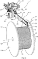
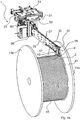
- the winding device 1 is used to wind a plastic pipe 3 continuously extruded from an extrusion station (not shown), such as a so-called cable protection pipe, onto a winding drum 5, with the most uniform possible winding without a gap between the individual winding loops 17 and with a substantially constant winding pitch of a plastic pipe width per Rotation is to be achieved, for example in the Figures 1 to 4b is shown.
- the winding drum 5 comprises an essentially cylindrical drum core 7, at each of the two axial ends of which a lateral side flange 11a, 11b extending in the radial direction is attached.
- a rotation axis 13 of the winding drum 5 is fixedly mounted (with respect to a reference base B on which the winding device 1 stands), around which the winding drum 5 rotates to carry out the winding process.
- the axis of rotation 13 defines an axial direction to which reference is also made below for the definition of movements of movable components of the winding device 1.
- the standardized winding drum 5 is often made of wood, with the drum core 7 and also the side flanges 11a, 11b being able to deviate slightly, but not negligibly, from an ideally symmetrical shape.
- the cylindrical drum core 7 can have radial runouts, while the side flanges 11a, 11b can form axial imbalances.
- the extruded plastic pipe 3 is already wrapped around the drum core 7 by more than the axial half of the winding drum 5 in an initial winding layer.
- the winding loop applied last to the drum core 7 is to be provided with the reference number 17.
- the winding loop 17 has, until the next winding loop has been laid completely circumferentially and has laid itself laterally, a circumferentially free axial lateral side 18, which is referred to in the following primarily at a point around 12 o'clock on the circumference (contact with engagement wheel 43) shall be.
- the plastic pipe 3 is continuously extruded cylindrically along its extension and can have an outer diameter of 5 mm to 30 mm or 40 mm.
- the thickness of the plastic pipe 3 can be around 10% to 60% of the outer pipe radius.
- the plastic pipe 3 is continuously formed in an extrusion station (not shown) and passes via a cooling line (water bath) into the winding device 1, which can be preceded by a plastic pipe (3) buffer system (not shown) through which the different conveying speeds of the Plastic pipe 3 should be compensated in the longitudinal direction during the extrusion process and when winding.
- the buffer system can be designed as a vertical pendulum, for example, which can compensate for too low / too high a speed of the winding device 1 compared to the extrusion device due to the vertical displaceability of a deflection wheel by the deflection wheel occupying a higher / lower vertical position. In this way, a buffer section for the extruded plastic pipe (3) for a continuous production process can be achieved before it reaches the winding device 1.
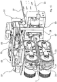
- the winding device 1 consists essentially of four main components, namely a carrier 23, a laying arm 27, a restoring device 61 as well as only one in Figure 5 indicated positioning robot 71.
- the laying arm 27 has a shape like a chainsaw with a laying arm base 28 (actuator / motor base) and a laying sword 29, which extends from the laying arm base 28 essentially in the horizontal direction to the winding drum 5 and touches it directly or indirectly.
- the laying arm base 28 has a receptacle 21 on its end face facing away from the winding drum 5 ( Figures 6 , 9 and 10 ) to accept the plastic tube 3, in particular continuously leaving an extrusion station.
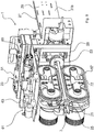
- the receptacle 21 comprises pairs of rollers 25 arranged in a star shape, which delimit a threading opening by a horizontal and to ensure vertically guided threading of the plastic pipe 3 into the laying arm 27.
- the laying arm base 28 is mainly formed by a profile support 57 which is composed of several support plates joined to one another. Functional components of the winding device 1, such as a microcomputer, actuators, etc., can be attached to the support plates.
- the carrier 23 movably holds the laying arm 27 and, in the embodiment shown, has a rail 51 to which a gripping arm of the positioning robot 71 is attached.
- the rail 51 cooperates with a slide 53 of the traverse arm base 28 such that the traverse arm 27 can be moved back and forth along the linear slide path.
- the laying bar 29 extends predominantly in a horizontal direction, approximately perpendicular to the axial direction 13 away from the laying arm base 28 towards the winding drum 5, the laying arm 27 being dimensioned in such a way that it extends over the drum core 7 in its longitudinal direction (up to approximately its axial center). protrudes (viewed in lifting direction A).
- the laying sword 29 has two vertical guide and holding plates 31a, 31b arranged parallel to one another.
- a guide gap for the plastic pipe 3 is formed between the two holding and guide plates 31a, 31b, which have a substantially constant vertical width in their substantially horizontal extension direction. So that the plastic pipe 3 can slide safely from the receptacle 21 along the laying arm 27 between the holding and guide plates 31a, 31b, guide rollers can be rotatably mounted in the guide gap on the holding and guide plates 31a, 31b and a location-defined guide channel through the guide gap form.
- a pair of delivery rollers 35 with horizontal axes of rotation are still mounted in the guide gap, which ensure a guided delivery of the plastic pipe 3 from the end 33 of the laying arm 27 on the winding drum side to the winding drum 5.
- a displacement sensor in the form of a contactor 37 is positioned on an upper side of the end 33 on the winding drum side.
- the contactor 37 comprises a freely rotatably mounted contact wheel whose axis of rotation is arranged vertically.
- Another displacement sensor system known from the prior art can also be used.
- the contact wheel is in a passive operating state in the course of the laying movement W of the laying arm 27 between the left side flange 11b and the opposite right side flange 11a, in which the axis of rotation lies in a guide gap of the laying sword 29.
- the contact wheel of the contactor 37 As soon as the contact wheel of the contactor 37 comes into engagement with the radial inside 41 of the respective side flange 11a, 11b, the contact wheel, in particular its vertical axis of rotation, is deflected in the axial direction because the contact wheel at the end 33 of the transfer arm 27 on the winding drum side is axially in both axial directions protrudes and is pivotably mounted on the laying arm 27 for an axial deflection.
- the contactor 37 sends an electrical contact signal to a control and / or regulating device (not shown in greater detail) which processes the contact signal for the further winding operation of the winding device 1.
- an engaging wheel 43 is mounted in a freely rotatable manner on the laying arm 27, the axis of rotation of which is essentially horizontally parallel to the axis of rotation 13 of the winding drum 5.
- the running surface of the engagement wheel 43 is in direct rolling contact with the driven drum core 7 or an already laid winding layer.
- a freely accessible side area of the engagement wheel 43 rests against the axial lateral side 18 of the most recently laid winding loop 17 during winding with a predominantly axial pressure pretensioning contact.
- the axial width of the running surface of the engagement wheel 43 is dimensioned in such a way that it is greater than half the outer diameter of the plastic pipe 3, but smaller than the outer diameter of the plastic pipe 3.
- the laying arm 27 is mounted so that it can pivot vertically via a carrier-side (23) pivot bearing, which is not illustrated in more detail, with a carrier-side pivot axis S running horizontally, at least depending on the laying path position, parallel to the axis of rotation 13 of the winding drum 5.
- a damping unit 45 is provided, which is fastened on the one hand to the carrier 23 and on the other hand to a projection 47 on the top of the laying sword 29.
- the damping unit 45 ensures a damped pivoting movement of the laying arm 27 about the pivot axis S on the carrier side.
- a pivot stop (not shown) is provided which limits the pivoting of the laying arm 27 downward in the vertical plane onto the winding drum 5.
- the swivel stop ensures that the engagement wheel 43 does not push between two already laid winding loops and push itself through completely between them in order to avoid contact engagement of the engagement wheel 43 with a complete winding layer underneath.
- the pivoting mobility of the traversing arm 27 and the position of the pivoting stop are set relative to the traversing arm 27 such that the engagement wheel 43 is in rolling contact with the cylindrical drum core 7 or the most recently laid winding position during the to-and-fro movement.
- the pivot stop stops the engaging roller 43 from being lowered from at most half the thickness of the plastic pipe 3, so that rolling contact on the most recently completely laid winding layer is prevented.
- the carrier 23 can be displaced relative to the fixed axis of rotation 13 or to the fixed reference floor B of a production hall by one of the positioning robots 71, which is fixedly mounted on the reference floor B, grasping the carrier 23, holding it and positioning it according to the winding process.
- the point of engagement of the engagement wheel 43 with the drum core 7 or the already laid winding layer forms an actuation point at which the laying arm 27 is axially displaced in advance relative to the carrier 23 by the axial growth of the winding layer 15.
- This can be referred to as a flexibly reacting subsequent movement of the laying arm 27, which immediately follows the continuous axial laying of the winding loops 17 and the axial growth of the winding layer 15.
- a vertical pivoting movement about the pivot axis S due to the engagement of the engagement wheel 43 on the winding drum 5 and a radial growth of the winding layers realizes a subsequent readjustment of the laying arm 27, which is initially mounted on the stationary carrier 23.
- the yielding movement of the laying arm 27 and the adjustment movement of the carrier 23 are with the double arrows V, A in Figure 5 indicated.
- the positioning robot 71 holds the carrier 23 by means of the rail 51, which cooperates with the slide 53, which is formed from a base plate 55 and a profile carrier 57 extending downward therefrom.
- the slide 53 and the rail 51 form a translational bearing, the translational displacement direction V of which is defined essentially or approximately parallel to the horizontal axial direction (axis of rotation 13).
- the carriage (53) -rail (51) arrangement gives the laying arm 27 freedom of movement with respect to the carrier 23 only in the laying direction V, so that the carriage 53 only in the laying direction V relative to the positioning robot 71, in particular its gripping arm (not shown). , can be relocated.
- the rail (51) -slide (53) arrangement provides axial compliance for the traverse arm 27.
- the axial flexibility is created by the degree of freedom of movement in the laying direction V. So that the engaging wheel 43 does not lose contact with the lateral side of the most recently laid winding loop 17 during the laying process between the two side flanges 11a, 11b, a restoring or prestressing device 61 acts between the carriage 53 and the rail 51, which creates an elastic restoring or prestressing force generated as soon as the laying arm 27 is deflected from a predefined neutral position relative to the carrier 23, in which no restoring forces of the restoring device 61 act between the rail 51 and the slide 53, in the laying direction V, driven by the axial expansion of the winding layer 15.
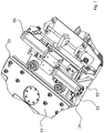
- the reset device 61 is formed by a pair of pneumatic actuators 63, 65, the details of which are shown in FIGS Figures 7 to 10 are indicated.
- a pneumatic actuator 65 or 63 is only active in one of the displacement directions V (for example from the side flange 11a to the side flange 11b) for generating the restoring force, while the other pneumatic actuator (65 or 63) is active in the opposite displacement direction V (from the side flange 11b to the side flange 11a) is active.
- the end 33 of the laying arm 27 together with the slide 53 is displaced in the linear laying direction V relative to the rail 51, which remains unaffected temporarily in its position until it is readjusted, for example, when a deflection threshold of the carriage 53 is exceeded by the positioning robot 71, which reduces the restoring force of the restoring device.
- the pneumatic actuator 63 or 65 (depending on the axial Laying direction) pneumatically so that the pneumatic elastic restoring force is generated in the pneumatic actuator 63, 65, which is communicated to the laying arm 27 via the carriage 53 and finally prestresses the engagement wheel 43 axially against the free lateral side 18 of the last wound loop 17.
- the axial restoring preload ensures that all winding loops 17 are placed close to one another in the axial direction in order to achieve the desired uniform winding sequence and that geometrical and material-specific anomalies can be flexibly adapted.
- the pneumatic actuator 63, 65 can also generate an actively controlled, pneumatic restoring force independently of the relocation of the traversing arm 27, for example by activating the pneumatic actuator via a control and / or regulating device, for example, depending on a predetermined operating state is activated pneumatically.
- the pneumatic actuator 63 is uncontrolled and (only) builds up elastic restoring forces when the laying arm 27 is displaced from its neutral position in the laying direction V.
- the axial deflection between the carriage 53 and the rail 51 is kept essentially constant or at least in a limit area.
- a position sensor (not shown) is used, which monitors a predefined minimum and maximum target deflection amplitude with the aid of a control and / or regulating device (not shown in more detail). If this is exceeded or not reached, the positioning robot 71 moves the rail 51 following the deflection movement of the laying arm 27, wherein the step up can correspond approximately to the thickness of the plastic pipe 3. In this way it is ensured that the elastic restoring force is reduced by following the rail 51 by the periodic build-up of the deflection.
- the plastic tube 3 is subjected to a constant tensile prestressing force as far as possible in its longitudinal direction when it is wound around the drum core 7.
- an electromagnetic brake in particular an eddy current brake 67
- the eddy current brake 67 which can optionally be set and manipulated by a control and / or regulating device that is not detailed, serves to communicate the essentially uniform tensile prestressing force to the plastic pipe 3.
- the eddy current brake 67 can have two magnet rotors that rotate in an electromagnetically generated magnetic field, wherein the respective magnet rotor can be retracted and extended in order to adjust the electromagnetic braking force.
- a toothed belt 72 is provided, which is tensioned around two deflection rollers of the eddy current brake 67.
- the toothed belt 72 has transverse teeth in order to ensure a desired engagement with the plastic pipe 3 and the transmission of frictional force.
- a mountain-valley profile running in the longitudinal direction can also be provided, which is shaped to complement the plastic tube 3.
- this causes the laying arm 27 to be lifted vertically, in that the positioning robot 71 does not raise the carrier 23 and its rail 51 in the lifting direction A by more than the thickness of the plastic pipe 3, but not closer
- the vertical pivot stop shown takes the laying arm 27 with it in the vertical lifting direction in order to raise the end 33 of the laying arm 27 on the winding drum side by slightly more than the outer diameter of the plastic pipe 3 over the winding layer 15 that has just ended.
- This operating state of the raised winding drum-side end 33 is in the Figures 3a and 3b can be seen, as is the deflected contactor 37. In the axial end position of the end 33 of the laying arm 27 on the winding drum side, there is temporarily no contact between the engagement wheel 43 and the plastic tube 3.
- That the laying arm 27 is already deflected away from the axial end position can also be seen from the position of the contact wheel of the contactor 37, which is again in the passive operating state and is no longer in rolling contact with the inside 41 of the side flange 11a.
- a (positive) angle of incidence ⁇ decreases, so that the longitudinal extent of the laying arm 27 coincides with the horizontal radial direction H R approximately in the axial center of the winding drum 5, while the laying arm 27 in the opposite axial laying end position is also inclined towards the center of the winding drum 5 at a (negative) angle of incidence ⁇ , in particular of the same size.
- the contactor 37 can reliably trigger by pivoting the contact wheel to the side.
- the side flange 11a, 11b extending in the radial direction does not conflict with the movement of the laying arm 27 inclined in relation thereto.
Landscapes
- Winding Filamentary Materials (AREA)
- Moulding By Coating Moulds (AREA)
- Winding Of Webs (AREA)
Priority Applications (1)
| Application Number | Priority Date | Filing Date | Title |
|---|---|---|---|
| PL13829060T PL2953876T3 (pl) | 2013-02-06 | 2013-12-20 | Urządzenie i sposób nawijania pasmowego materiału nawojowego |
Applications Claiming Priority (6)
| Application Number | Priority Date | Filing Date | Title |
|---|---|---|---|
| DE102013002019.0A DE102013002019B4 (de) | 2013-02-06 | 2013-02-06 | Wickelungsvorrichtung für ein strangförmiges Wickelgut und Verfahren dazu |
| DE102013002022.0A DE102013002022B4 (de) | 2013-02-06 | 2013-02-06 | Vorrichtung zum Wickeln eines strangförmigen Wickelguts und Verfahren dazu |
| DE102013002023.9A DE102013002023B4 (de) | 2013-02-06 | 2013-02-06 | Vorrichtung und Verfahren zum Wickeln eines strangförmigen Wickelguts |
| DE102013002017.4A DE102013002017B4 (de) | 2013-02-06 | 2013-02-06 | Wickelungsvorrichtung und -verfahren für ein strangförmiges Wickelgut |
| DE102013002020.4A DE102013002020B4 (de) | 2013-02-06 | 2013-02-06 | Wickelungsvorrichtung und Wickelungsverfahren für ein strangförmiges Wickelgut |
| PCT/EP2013/003930 WO2014121812A2 (de) | 2013-02-06 | 2013-12-20 | Vorrichtung und verfahren zum wickeln eines strangförmigen wickelguts |
Publications (2)
| Publication Number | Publication Date |
|---|---|
| EP2953876A2 EP2953876A2 (de) | 2015-12-16 |
| EP2953876B1 true EP2953876B1 (de) | 2020-11-11 |
Family
ID=50101852
Family Applications (1)
| Application Number | Title | Priority Date | Filing Date |
|---|---|---|---|
| EP13829060.6A Active EP2953876B1 (de) | 2013-02-06 | 2013-12-20 | Vorrichtung und verfahren zum wickeln eines strangförmigen wickelguts |
Country Status (7)
| Country | Link |
|---|---|
| EP (1) | EP2953876B1 (da) |
| DK (1) | DK2953876T3 (da) |
| ES (1) | ES2851573T3 (da) |
| HU (1) | HUE053166T2 (da) |
| PL (1) | PL2953876T3 (da) |
| PT (1) | PT2953876T (da) |
| WO (1) | WO2014121812A2 (da) |
Families Citing this family (2)
| Publication number | Priority date | Publication date | Assignee | Title |
|---|---|---|---|---|
| DE102013109056B3 (de) * | 2013-08-21 | 2014-08-14 | Graewe GmbH | Microductrohrwickler, Doppelstellenwickler, Verarbeitungssystem für Microduct-Kunststoffleerrohre und Verfahren zum Aufwickeln solcher Rohre |
| CN112141815B (zh) * | 2020-10-20 | 2022-06-07 | 湖南腾博复合材料有限公司 | 一种环式结构型调节绕线装置 |
Citations (4)
| Publication number | Priority date | Publication date | Assignee | Title |
|---|---|---|---|---|
| GB1194825A (en) * | 1966-07-06 | 1970-06-10 | Marshall Richards Barcro Ltd | Improvements in and relating to Spooling of Filamentary Materials |
| US4124340A (en) * | 1977-01-25 | 1978-11-07 | Phillips Petroleum Company | Control of pipe tension between extruder die and take-up coiler |
| EP0049552A1 (en) * | 1980-10-08 | 1982-04-14 | Wavin B.V. | Apparatus for coiling flexible stretched materials, particularly tubes or cables |
| GB2137239A (en) * | 1983-03-31 | 1984-10-03 | Morgan Construction Co | Coiling systems |
Family Cites Families (7)
| Publication number | Priority date | Publication date | Assignee | Title |
|---|---|---|---|---|
| GB1328542A (en) * | 1971-04-19 | 1973-08-30 | British Insulated Callenders | Apparatus for winding electric cables and the like |
| AU495293B2 (en) * | 1974-08-27 | 1976-03-04 | Sumitomo Electric Industries, Ltd. | Automatic cable winding apparatus |
| JPS6011872Y2 (ja) * | 1978-08-30 | 1985-04-18 | タツタ電線株式会社 | 綾ねじ型トラバ−ス装置 |
| DE3308283C2 (de) * | 1983-03-09 | 1987-04-23 | Siemens AG, 1000 Berlin und 8000 München | Vorrichtung und Verfahren zum Aufwickeln von Kabeln oder biegsamen Leitungen auf Trommeln und ein Verfahren zum Justieren der Vorrichtung von Beginn des Wickelvorganges |
| SE8601484L (sv) | 1985-04-29 | 1986-10-30 | Skaltek Ab | Arm for upplindning av en kabel |
| DE3612743A1 (de) * | 1986-04-16 | 1987-10-22 | Prym Werke William | Verlegeeinrichtung fuer spulmaschinen |
| JP2621906B2 (ja) * | 1988-02-25 | 1997-06-18 | 宇部日東化成株式会社 | 線状物の整列巻取り装置 |
-
2013
- 2013-12-20 PT PT138290606T patent/PT2953876T/pt unknown
- 2013-12-20 WO PCT/EP2013/003930 patent/WO2014121812A2/de not_active Ceased
- 2013-12-20 EP EP13829060.6A patent/EP2953876B1/de active Active
- 2013-12-20 HU HUE13829060A patent/HUE053166T2/hu unknown
- 2013-12-20 ES ES13829060T patent/ES2851573T3/es active Active
- 2013-12-20 PL PL13829060T patent/PL2953876T3/pl unknown
- 2013-12-20 DK DK13829060.6T patent/DK2953876T3/da active
Patent Citations (4)
| Publication number | Priority date | Publication date | Assignee | Title |
|---|---|---|---|---|
| GB1194825A (en) * | 1966-07-06 | 1970-06-10 | Marshall Richards Barcro Ltd | Improvements in and relating to Spooling of Filamentary Materials |
| US4124340A (en) * | 1977-01-25 | 1978-11-07 | Phillips Petroleum Company | Control of pipe tension between extruder die and take-up coiler |
| EP0049552A1 (en) * | 1980-10-08 | 1982-04-14 | Wavin B.V. | Apparatus for coiling flexible stretched materials, particularly tubes or cables |
| GB2137239A (en) * | 1983-03-31 | 1984-10-03 | Morgan Construction Co | Coiling systems |
Also Published As
| Publication number | Publication date |
|---|---|
| DK2953876T3 (da) | 2021-01-11 |
| WO2014121812A3 (de) | 2014-10-23 |
| PT2953876T (pt) | 2021-02-03 |
| PL2953876T3 (pl) | 2021-06-14 |
| EP2953876A2 (de) | 2015-12-16 |
| WO2014121812A2 (de) | 2014-08-14 |
| HUE053166T2 (hu) | 2021-06-28 |
| ES2851573T3 (es) | 2021-09-07 |
Similar Documents
| Publication | Publication Date | Title |
|---|---|---|
| DE102013002020B4 (de) | Wickelungsvorrichtung und Wickelungsverfahren für ein strangförmiges Wickelgut | |
| DE102013002017B4 (de) | Wickelungsvorrichtung und -verfahren für ein strangförmiges Wickelgut | |
| DE102013002022B4 (de) | Vorrichtung zum Wickeln eines strangförmigen Wickelguts und Verfahren dazu | |
| DE102014001134B4 (de) | Wickelungsvorrichtung für ein strangförmiges Wickelgut und Verfahren dazu | |
| EP2815857B1 (de) | Schere | |
| DE102013002023B4 (de) | Vorrichtung und Verfahren zum Wickeln eines strangförmigen Wickelguts | |
| EP3099613B1 (de) | Vorrichtung und verfahren zum wickeln eines strangförmigen wickelguts | |
| DE102007053588A1 (de) | Abrollvorrichtung für Wickelrollen | |
| DE2917295A1 (de) | Wickelsystem fuer metallische straenge | |
| DE4128970A1 (de) | Abschervorrichtung | |
| DE102013002019B4 (de) | Wickelungsvorrichtung für ein strangförmiges Wickelgut und Verfahren dazu | |
| DE19541095C2 (de) | Verfahren zur Förderung eines Bandes aus plastischem Material und Fördertisch zur kontinuierlichen Förderung von bandförmigem plastischem Material | |
| EP0481323B1 (de) | Verfahren zum Beschicken einer Bearbeitungsmaschine mit einem Feinzentrierschritt und Vorrichtung hierfür | |
| DE102014001058B4 (de) | Vorrichtung und Verfahren zum Wickeln eines strangförmigen Wickelguts | |
| EP3099614B1 (de) | Verlegearm für eine vorrichtung zum wickeln eines strangförmigen wickelguts | |
| EP3810345B1 (de) | Vorrichtung und verfahren zum transportieren von bandmaterial, insbesondere warmband | |
| DE3308283C2 (de) | Vorrichtung und Verfahren zum Aufwickeln von Kabeln oder biegsamen Leitungen auf Trommeln und ein Verfahren zum Justieren der Vorrichtung von Beginn des Wickelvorganges | |
| DE102006012972B4 (de) | Vorrichtung zur Regelung des seitlichen Versatzes von Materialbahnen | |
| WO2014121812A2 (de) | Vorrichtung und verfahren zum wickeln eines strangförmigen wickelguts | |
| DE102014001135B3 (de) | Verlegearm für eine Vorrichtung zum Wickeln eines strangförmigen Wickelguts | |
| DE19944295A1 (de) | Aufrollvorrichtung | |
| DE69721848T2 (de) | Aufwickler | |
| DE102012213966B4 (de) | Vorrichtung zum Ausrichten eines Rollentransportmittels im Transportweg einer an einem Rollenwechsler aufzuachsenden Materialrolle | |
| DE102014001057A1 (de) | Verlegearm für eine Vorrichtung zum Wickeln eines strangförmigen Wickelguts | |
| DE102006018642A1 (de) | Vorrichtung zum Erfassen von Parametern einer Kante eines Materialstückes und zum Regeln des Versatzes desselben |
Legal Events
| Date | Code | Title | Description |
|---|---|---|---|
| PUAI | Public reference made under article 153(3) epc to a published international application that has entered the european phase |
Free format text: ORIGINAL CODE: 0009012 |
|
| 17P | Request for examination filed |
Effective date: 20150731 |
|
| AK | Designated contracting states |
Kind code of ref document: A2 Designated state(s): AL AT BE BG CH CY CZ DE DK EE ES FI FR GB GR HR HU IE IS IT LI LT LU LV MC MK MT NL NO PL PT RO RS SE SI SK SM TR |
|
| AX | Request for extension of the european patent |
Extension state: BA ME |
|
| DAX | Request for extension of the european patent (deleted) | ||
| STAA | Information on the status of an ep patent application or granted ep patent |
Free format text: STATUS: EXAMINATION IS IN PROGRESS |
|
| 17Q | First examination report despatched |
Effective date: 20171215 |
|
| GRAP | Despatch of communication of intention to grant a patent |
Free format text: ORIGINAL CODE: EPIDOSNIGR1 |
|
| STAA | Information on the status of an ep patent application or granted ep patent |
Free format text: STATUS: GRANT OF PATENT IS INTENDED |
|
| INTG | Intention to grant announced |
Effective date: 20200529 |
|
| GRAS | Grant fee paid |
Free format text: ORIGINAL CODE: EPIDOSNIGR3 |
|
| GRAA | (expected) grant |
Free format text: ORIGINAL CODE: 0009210 |
|
| STAA | Information on the status of an ep patent application or granted ep patent |
Free format text: STATUS: THE PATENT HAS BEEN GRANTED |
|
| AK | Designated contracting states |
Kind code of ref document: B1 Designated state(s): AL AT BE BG CH CY CZ DE DK EE ES FI FR GB GR HR HU IE IS IT LI LT LU LV MC MK MT NL NO PL PT RO RS SE SI SK SM TR |
|
| REG | Reference to a national code |
Ref country code: GB Ref legal event code: FG4D Free format text: NOT ENGLISH |
|
| REG | Reference to a national code |
Ref country code: CH Ref legal event code: EP |
|
| REG | Reference to a national code |
Ref country code: AT Ref legal event code: REF Ref document number: 1333265 Country of ref document: AT Kind code of ref document: T Effective date: 20201115 |
|
| REG | Reference to a national code |
Ref country code: DE Ref legal event code: R096 Ref document number: 502013015298 Country of ref document: DE |
|
| REG | Reference to a national code |
Ref country code: IE Ref legal event code: FG4D Free format text: LANGUAGE OF EP DOCUMENT: GERMAN |
|
| REG | Reference to a national code |
Ref country code: DK Ref legal event code: T3 Effective date: 20210108 |
|
| REG | Reference to a national code |
Ref country code: CH Ref legal event code: NV Representative=s name: TROESCH SCHEIDEGGER WERNER AG, CH |
|
| REG | Reference to a national code |
Ref country code: PT Ref legal event code: SC4A Ref document number: 2953876 Country of ref document: PT Date of ref document: 20210203 Kind code of ref document: T Free format text: AVAILABILITY OF NATIONAL TRANSLATION Effective date: 20210127 |
|
| REG | Reference to a national code |
Ref country code: FI Ref legal event code: FGE |
|
| REG | Reference to a national code |
Ref country code: SE Ref legal event code: TRGR |
|
| REG | Reference to a national code |
Ref country code: NL Ref legal event code: FP |
|
| REG | Reference to a national code |
Ref country code: NO Ref legal event code: T2 Effective date: 20201111 |
|
| PG25 | Lapsed in a contracting state [announced via postgrant information from national office to epo] |
Ref country code: RS Free format text: LAPSE BECAUSE OF FAILURE TO SUBMIT A TRANSLATION OF THE DESCRIPTION OR TO PAY THE FEE WITHIN THE PRESCRIBED TIME-LIMIT Effective date: 20201111 Ref country code: GR Free format text: LAPSE BECAUSE OF FAILURE TO SUBMIT A TRANSLATION OF THE DESCRIPTION OR TO PAY THE FEE WITHIN THE PRESCRIBED TIME-LIMIT Effective date: 20210212 |
|
| PG25 | Lapsed in a contracting state [announced via postgrant information from national office to epo] |
Ref country code: IS Free format text: LAPSE BECAUSE OF FAILURE TO SUBMIT A TRANSLATION OF THE DESCRIPTION OR TO PAY THE FEE WITHIN THE PRESCRIBED TIME-LIMIT Effective date: 20210311 Ref country code: LV Free format text: LAPSE BECAUSE OF FAILURE TO SUBMIT A TRANSLATION OF THE DESCRIPTION OR TO PAY THE FEE WITHIN THE PRESCRIBED TIME-LIMIT Effective date: 20201111 Ref country code: BG Free format text: LAPSE BECAUSE OF FAILURE TO SUBMIT A TRANSLATION OF THE DESCRIPTION OR TO PAY THE FEE WITHIN THE PRESCRIBED TIME-LIMIT Effective date: 20210211 |
|
| REG | Reference to a national code |
Ref country code: LT Ref legal event code: MG9D |
|
| REG | Reference to a national code |
Ref country code: HU Ref legal event code: AG4A Ref document number: E053166 Country of ref document: HU |
|
| PG25 | Lapsed in a contracting state [announced via postgrant information from national office to epo] |
Ref country code: HR Free format text: LAPSE BECAUSE OF FAILURE TO SUBMIT A TRANSLATION OF THE DESCRIPTION OR TO PAY THE FEE WITHIN THE PRESCRIBED TIME-LIMIT Effective date: 20201111 |
|
| PG25 | Lapsed in a contracting state [announced via postgrant information from national office to epo] |
Ref country code: SK Free format text: LAPSE BECAUSE OF FAILURE TO SUBMIT A TRANSLATION OF THE DESCRIPTION OR TO PAY THE FEE WITHIN THE PRESCRIBED TIME-LIMIT Effective date: 20201111 Ref country code: RO Free format text: LAPSE BECAUSE OF FAILURE TO SUBMIT A TRANSLATION OF THE DESCRIPTION OR TO PAY THE FEE WITHIN THE PRESCRIBED TIME-LIMIT Effective date: 20201111 Ref country code: LT Free format text: LAPSE BECAUSE OF FAILURE TO SUBMIT A TRANSLATION OF THE DESCRIPTION OR TO PAY THE FEE WITHIN THE PRESCRIBED TIME-LIMIT Effective date: 20201111 Ref country code: SM Free format text: LAPSE BECAUSE OF FAILURE TO SUBMIT A TRANSLATION OF THE DESCRIPTION OR TO PAY THE FEE WITHIN THE PRESCRIBED TIME-LIMIT Effective date: 20201111 Ref country code: EE Free format text: LAPSE BECAUSE OF FAILURE TO SUBMIT A TRANSLATION OF THE DESCRIPTION OR TO PAY THE FEE WITHIN THE PRESCRIBED TIME-LIMIT Effective date: 20201111 |
|
| REG | Reference to a national code |
Ref country code: DE Ref legal event code: R097 Ref document number: 502013015298 Country of ref document: DE |
|
| PG25 | Lapsed in a contracting state [announced via postgrant information from national office to epo] |
Ref country code: MC Free format text: LAPSE BECAUSE OF FAILURE TO SUBMIT A TRANSLATION OF THE DESCRIPTION OR TO PAY THE FEE WITHIN THE PRESCRIBED TIME-LIMIT Effective date: 20201111 |
|
| REG | Reference to a national code |
Ref country code: ES Ref legal event code: FG2A Ref document number: 2851573 Country of ref document: ES Kind code of ref document: T3 Effective date: 20210907 |
|
| PLBE | No opposition filed within time limit |
Free format text: ORIGINAL CODE: 0009261 |
|
| STAA | Information on the status of an ep patent application or granted ep patent |
Free format text: STATUS: NO OPPOSITION FILED WITHIN TIME LIMIT |
|
| 26N | No opposition filed |
Effective date: 20210812 |
|
| PG25 | Lapsed in a contracting state [announced via postgrant information from national office to epo] |
Ref country code: AL Free format text: LAPSE BECAUSE OF FAILURE TO SUBMIT A TRANSLATION OF THE DESCRIPTION OR TO PAY THE FEE WITHIN THE PRESCRIBED TIME-LIMIT Effective date: 20201111 |
|
| PG25 | Lapsed in a contracting state [announced via postgrant information from national office to epo] |
Ref country code: SI Free format text: LAPSE BECAUSE OF FAILURE TO SUBMIT A TRANSLATION OF THE DESCRIPTION OR TO PAY THE FEE WITHIN THE PRESCRIBED TIME-LIMIT Effective date: 20201111 |
|
| PG25 | Lapsed in a contracting state [announced via postgrant information from national office to epo] |
Ref country code: IS Free format text: LAPSE BECAUSE OF FAILURE TO SUBMIT A TRANSLATION OF THE DESCRIPTION OR TO PAY THE FEE WITHIN THE PRESCRIBED TIME-LIMIT Effective date: 20210311 Ref country code: TR Free format text: LAPSE BECAUSE OF FAILURE TO SUBMIT A TRANSLATION OF THE DESCRIPTION OR TO PAY THE FEE WITHIN THE PRESCRIBED TIME-LIMIT Effective date: 20201111 Ref country code: MT Free format text: LAPSE BECAUSE OF FAILURE TO SUBMIT A TRANSLATION OF THE DESCRIPTION OR TO PAY THE FEE WITHIN THE PRESCRIBED TIME-LIMIT Effective date: 20201111 Ref country code: CY Free format text: LAPSE BECAUSE OF FAILURE TO SUBMIT A TRANSLATION OF THE DESCRIPTION OR TO PAY THE FEE WITHIN THE PRESCRIBED TIME-LIMIT Effective date: 20201111 |
|
| PG25 | Lapsed in a contracting state [announced via postgrant information from national office to epo] |
Ref country code: MK Free format text: LAPSE BECAUSE OF FAILURE TO SUBMIT A TRANSLATION OF THE DESCRIPTION OR TO PAY THE FEE WITHIN THE PRESCRIBED TIME-LIMIT Effective date: 20201111 |
|
| REG | Reference to a national code |
Ref country code: DE Ref legal event code: R082 Ref document number: 502013015298 Country of ref document: DE Representative=s name: SKM-IP SCHMID KRAUSS KUTTENKEULER MALESCHA SCH, DE |
|
| P01 | Opt-out of the competence of the unified patent court (upc) registered |
Effective date: 20230527 |
|
| REG | Reference to a national code |
Ref country code: CH Ref legal event code: U11 Free format text: ST27 STATUS EVENT CODE: U-0-0-U10-U11 (AS PROVIDED BY THE NATIONAL OFFICE) Effective date: 20260101 |
|
| PGFP | Annual fee paid to national office [announced via postgrant information from national office to epo] |
Ref country code: GB Payment date: 20251218 Year of fee payment: 13 |
|
| PGFP | Annual fee paid to national office [announced via postgrant information from national office to epo] |
Ref country code: NO Payment date: 20251216 Year of fee payment: 13 |
|
| PGFP | Annual fee paid to national office [announced via postgrant information from national office to epo] |
Ref country code: AT Payment date: 20251215 Year of fee payment: 13 Ref country code: PT Payment date: 20251219 Year of fee payment: 13 |
|
| PGFP | Annual fee paid to national office [announced via postgrant information from national office to epo] |
Ref country code: FI Payment date: 20251216 Year of fee payment: 13 Ref country code: DK Payment date: 20251217 Year of fee payment: 13 |
|
| PGFP | Annual fee paid to national office [announced via postgrant information from national office to epo] |
Ref country code: LU Payment date: 20251216 Year of fee payment: 13 Ref country code: HU Payment date: 20251215 Year of fee payment: 13 Ref country code: NL Payment date: 20251217 Year of fee payment: 13 Ref country code: FR Payment date: 20251218 Year of fee payment: 13 |
|
| PGFP | Annual fee paid to national office [announced via postgrant information from national office to epo] |
Ref country code: BE Payment date: 20251218 Year of fee payment: 13 |
|
| PGFP | Annual fee paid to national office [announced via postgrant information from national office to epo] |
Ref country code: SE Payment date: 20251217 Year of fee payment: 13 |
|
| PGFP | Annual fee paid to national office [announced via postgrant information from national office to epo] |
Ref country code: IE Payment date: 20251218 Year of fee payment: 13 Ref country code: CZ Payment date: 20251209 Year of fee payment: 13 |
|
| PGFP | Annual fee paid to national office [announced via postgrant information from national office to epo] |
Ref country code: PL Payment date: 20251208 Year of fee payment: 13 |
|
| PGFP | Annual fee paid to national office [announced via postgrant information from national office to epo] |
Ref country code: ES Payment date: 20260119 Year of fee payment: 13 |
|
| PGFP | Annual fee paid to national office [announced via postgrant information from national office to epo] |
Ref country code: DE Payment date: 20251222 Year of fee payment: 13 |
|
| PGFP | Annual fee paid to national office [announced via postgrant information from national office to epo] |
Ref country code: IT Payment date: 20251231 Year of fee payment: 13 |
|
| PGFP | Annual fee paid to national office [announced via postgrant information from national office to epo] |
Ref country code: CH Payment date: 20260101 Year of fee payment: 13 |