EP2953877B1 - Vorrichtung zum halten einer hülse um eine spindel - Google Patents
Vorrichtung zum halten einer hülse um eine spindel Download PDFInfo
- Publication number
- EP2953877B1 EP2953877B1 EP14701184.5A EP14701184A EP2953877B1 EP 2953877 B1 EP2953877 B1 EP 2953877B1 EP 14701184 A EP14701184 A EP 14701184A EP 2953877 B1 EP2953877 B1 EP 2953877B1
- Authority
- EP
- European Patent Office
- Prior art keywords
- mandrel
- retaining tab
- retaining
- sleeve
- expanded
- Prior art date
- Legal status (The legal status is an assumption and is not a legal conclusion. Google has not performed a legal analysis and makes no representation as to the accuracy of the status listed.)
- Not-in-force
Links
Images
Classifications
-
- B—PERFORMING OPERATIONS; TRANSPORTING
- B65—CONVEYING; PACKING; STORING; HANDLING THIN OR FILAMENTARY MATERIAL
- B65H—HANDLING THIN OR FILAMENTARY MATERIAL, e.g. SHEETS, WEBS, CABLES
- B65H75/00—Storing webs, tapes, or filamentary material, e.g. on reels
- B65H75/02—Cores, formers, supports, or holders for coiled, wound, or folded material, e.g. reels, spindles, bobbins, cop tubes, cans, mandrels or chucks
- B65H75/18—Constructional details
- B65H75/24—Constructional details adjustable in configuration, e.g. expansible
- B65H75/242—Expansible spindles, mandrels or chucks, e.g. for securing or releasing cores, holders or packages
- B65H75/245—Expansible spindles, mandrels or chucks, e.g. for securing or releasing cores, holders or packages by deformation of an elastic or flexible material
-
- B—PERFORMING OPERATIONS; TRANSPORTING
- B21—MECHANICAL METAL-WORKING WITHOUT ESSENTIALLY REMOVING MATERIAL; PUNCHING METAL
- B21C—MANUFACTURE OF METAL SHEETS, WIRE, RODS, TUBES, PROFILES OR LIKE SEMI-MANUFACTURED PRODUCTS OTHERWISE THAN BY ROLLING; AUXILIARY OPERATIONS USED IN CONNECTION WITH METAL-WORKING WITHOUT ESSENTIALLY REMOVING MATERIAL
- B21C47/00—Winding-up, coiling or winding-off metal wire, metal band or other flexible metal material characterised by features relevant to metal processing only
- B21C47/28—Drums or other coil-holders
- B21C47/30—Drums or other coil-holders expansible or contractible
-
- B—PERFORMING OPERATIONS; TRANSPORTING
- B65—CONVEYING; PACKING; STORING; HANDLING THIN OR FILAMENTARY MATERIAL
- B65H—HANDLING THIN OR FILAMENTARY MATERIAL, e.g. SHEETS, WEBS, CABLES
- B65H2301/00—Handling processes for sheets or webs
- B65H2301/40—Type of handling process
- B65H2301/41—Winding, unwinding
- B65H2301/417—Handling or changing web rolls
- B65H2301/418—Changing web roll
- B65H2301/4185—Core or mandrel discharge or removal, also organisation of core removal
- B65H2301/41852—Core or mandrel discharge or removal, also organisation of core removal by extracting mandrel from wound roll, e.g. in coreless applications
Definitions
- the present invention relates to a mandrel comprising a retaining device. It is a device for retaining a sleeve disposed around an expandable mandrel. More particularly, it is a device for retaining an elastic sleeve placed around an expandable mandrel intended to be driven for the winding and unwinding of coils. More specifically, the sleeve retainer included in the mandrel according to the invention is applicable to finishing lines for the continuous processing of metal strips.
- an elastic sleeve is generally placed on the mandrel.
- Such sleeves are described in the documents JP 2008229707 , JP 2005014091 and JP 11057853 .
- the elastic sleeve must be able to follow the movements of the mandrel while remaining integral with the latter when the coil is removed from the mandrel. It is common for this purpose to provide a retaining device of the elastic sleeve. This device must prevent the elastic sleeve from being extracted from the mandrel with the spool. This device is usually fixed by screws or other similar means. So, in the document JP 2000000613 , the retainer is secured with quarter-turn screws.
- Elastic sleeves have a limited life and therefore need to be replaced periodically. It is also necessary to change the sleeve when the diameter of the eye of the coil varies.
- the chuck Before removing the sleeve, the chuck must be fully retracted. The operator must stand in front of the chuck, unscrew the retainer and remove it. This is a dangerous operation because many machines work automatically at this location. It is therefore necessary for the operator to electrically, hydraulically, mechanically and pneumatically set the machines around the mandrel during assembly and disassembly of the retaining device of the elastic sleeve. Then only, the sleeve can be disassembled and a new sleeve can be introduced on the mandrel with the equipment necessary for this disconnected operation. After placement of the sleeve, the operator must again secure the retainer and, therefore, re-register all machines in the vicinity. As a result of all these operations a considerable loss of time will be all the more important if a handling machine for removing and placing the sleeve on the mandrel is also installed.
- the document is known EP 0 987 589 disclosing a camera material winding centering device provided with a retaining device formed of pivotally mounted lugs.
- the document is also known EP 1 564 014 disclosing a printer and a label stacking device.
- the feed mandrel is provided with a latch movably mounted on the rotational shaft of the mandrel and having at least one pair of shoulders engageable with opposite ends of the mandrel.
- a reel provided with means which hold it in position when it rotates, the means being movably mounted to release the reel when it is to be removed.
- the present invention aims to provide a mandrel comprising a sleeve retaining device to accelerate the sleeve changing process while avoiding the operator having to go to a dangerous area.
- the present invention relates to a mandrel comprising a radially movable part and a device for retained for a sleeve of annular section, said device comprising a support attached to or integrated in the mandrel and a retaining tab pivotally mounted about a direction axis parallel to the axis of the mandrel and on said support, said retaining tab being designed to be able, in use, to pivot from a first position where it covers a portion of the annular surface of the sleeve to a second position where it releases the annular surface of the sleeve, the pivoting from the first position to the second position or the reverse being , in use, actuated automatically by the radial displacement of the movable part of the mandrel.
- the present invention also relates to an assembly comprising a mandrel as described above and an elastic sleeve of annular section placed around said mandrel.
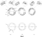
- the figure 2 represents above the retaining device according to the invention referred to an open-type mandrel and below corresponding expansion positions of the mandrel.
- the Fig.2 (a) (B) (vs) represent the same positions of the mandrel as those of the figure 1 .
- the present invention relates to a mandrel provided with a sleeve retaining device which is automatically retractable in order to accelerate the sleeve changing process and to prevent the operator from having to go to a danger zone.
- the present invention can be applied to radial expansion mandrels of different types of construction.
- the device can be integrated in the closing part of the mandrel.
- the support of the device can be attached to the mandrel.
- the expandable mandrel can move radially between three key positions: a completely expanded position, a half-expanded position and a full necking position.
- the mandrel is completely expanded during winding or unwinding of the tape.
- the mandrel is half-expanded when threading the reel to the uncoiler and when removing the reel from the reel.
- the mandrel is completely narrowed when the sleeve needs to be replaced.
- the retainer of the elastic sleeve must be retracted. However, it must be deployed to hold the sleeve on the mandrel when removing or threading the spool.
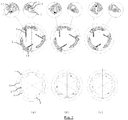
- the device according to the invention is represented in figures 1 and 2 for respectively a closed type mandrel and an open type mandrel.
- the device according to the invention comprises a retaining lug 1 mounted on a support 14 at an axial end of the mandrel.
- a retaining lug 1 mounted on a support 14 at an axial end of the mandrel.
- the support 14 of the retaining lug 1 is the chuck closing piece ( fig.1 ).
- Either the retaining device is mounted on an external support 14 to be connected to the mandrel ( fig.2 ), this construction being preferred when the chuck is open type.
- the pivot axis 3 of the retaining lug 1 is of direction parallel to the axis of the sleeve.
- the retaining lug 1 moves opposite the annular section of the sleeve 7.
- the retaining tab can adopt two working positions. In a first position, it is held in the deployed position by means of a pushing spring 2. In this position, the retaining tab makes obstacle to the axial displacement of the sleeve ( Fig.1-2 (a) and (B) ). In a second position, the pushing spring 2 is compressed for reasons explained below, and the retaining lug 1 is consequently retracted, thus no longer hindering the axial displacement of the sleeve 7 ( Fig.1-2 (c) ).
- the displacement of the retaining tab is related to the displacement of the parts of the chuck which are radially movable.
- a finger 5 fixed to a movable part of the mandrel cooperates with a recess 9 made in the retaining tab 1.
- the movable part is a wedge 6 positioned between two segments 8 of the mandrel and, in the case of an open mandrel ( fig.2 ), the radially movable portion is a segment 8 of the mandrel.
- the retaining lug 1 is held in the same extended position under the action of the pushing spring 2 when the mandrel is half-expanded or expanded.
- the recess 9 made in the retaining tab 1 is larger than the finger 5 of the mandrel and sized so that the movement of the finger 5 within the recess 9 does not cause movement of the paw of restraint 1 when moving parts of the mandrel move from their fully expanded position to their mid-expanded position.
- the finger 5 does not apply force to the wall of the recess 9 to compress the pushing spring 2 ( Fig.1-2 (a) and (B) ).
- the finger 5 bears against the wall of the recess 9 close to the axis of the mandrel and applies a sufficient force to the retaining lug 1 to compress the spring 2 ( Fig.1-2 (c) ).
- the retaining lug 1 is further provided with a groove 10 cooperating with an abutment 4 integral with the support 14 in order to limit the movement of the retaining lug 1 in the deployed position.
- the groove 10 and the stop 4 are dimensioned to prevent the retaining tab 1 from protruding from the outside diameter of the sleeve.
- the stop 4 also makes it possible to hold the retaining lug 1 in place despite the centrifugal forces.
- the sleeve retainer may be integrated or attached to the mandrel.
- the support 14 is attached to the open-type mandrel by means of the fastening elements which are the pins 11, screws 12, and key 13.
- FIG. 1 The present invention has been illustrated to figures 1 and 2 for example, two or three retaining tabs 1 may be distributed over the annular surface of the sleeve.
- the retaining device of the sleeve according to the invention is configured so as not to hinder the handling of the reel.
- the device according to the invention is compatible for sleeves of different diameters, for example 508 and 610 mm.
- the sleeve retainer may be applied to mandrels of different types of construction.
Landscapes
- Engineering & Computer Science (AREA)
- Mechanical Engineering (AREA)
- Winding Of Webs (AREA)
- Hand Tools For Fitting Together And Separating, Or Other Hand Tools (AREA)
Claims (13)
- Expandierbares Spannfutter, umfassend:eine Haltevorrichtung für eine Hülse (7) mit ringförmigem Querschnitt, umfassend einen mit dem Spannfutter verbundenen oder integrierten Träger (14) und eine Haltelasche (1), die auf dem Träger (14) um eine parallel zum Spannfutter verlaufende Achse (3) schwenkbar montiert ist, wobei die Haltelasche (1) derart konstruiert ist, dass sie sich im Einsatz von einer ersten Position, in der sie einen Teil der ringförmigen Oberfläche der Hülse (7) abdeckt, in eine zweite Position, in der die ringförmige Oberfläche der Hülse (7) frei liegt, schwenken kann, dadurch gekennzeichnet, dass das Spannfutter einen radial beweglichen Teil (6, 8) umfasst, und dass die Schwenkung von der ersten in die zweite Position (oder umgekehrt) im Einsatz automatisch durch die radiale Verschiebung des beweglichen Teils (6, 8) des Spannfutters herbeigeführt wird.
- Spannfutter nach Anspruch 1, wobei die Haltevorrichtung eine Treibfeder (2) umfasst, um die Haltelasche (1) in der ersten Position zu halten.
- Spannfutter nach Anspruch 1 oder 2, wobei die Haltelasche (1) eine Ausnehmung (9) und eine Nut (10) umfasst.
- Spannfutter nach einem der vorstehenden Ansprüche, wobei die Haltevorrichtung zwei oder drei Haltelaschen (1) umfasst.
- Spannfutter nach einem der vorstehenden Ansprüche, wobei die Treibfeder (2) derart dimensioniert ist, dass sie die Haltelasche (1) in der ersten Position hält wenn das Spannfutter ganz oder teilweise expandiert ist.
- Spannfutter nach einem der vorstehenden Ansprüche, umfassend einen auf dem radial beweglichen Teil (6, 8) positionierten Finger (5), der geeignet ist, im Einsatz in die Ausnehmung (9) in der Haltelasche (1) einzugreifen, wobei dieser Eingriff die Verschiebung der Haltelasche (1) von der ersten in die zweite Position ermöglicht, wenn sich das Spannfutter von einer ganz oder teilweise expandierten Position in eine ganz zurückgezogene Position versetzt.
- Spannfutter nach Anspruch 6, wobei die Ausnehmung (9) der Haltelasche (1) größer ist als der Finger (5), so dass das Zurückziehen des Spannfutters von einer expandierten in eine teilweise expandierte Position keine Verschiebung der Haltelasche (1) zur Folge hat.
- Spannfutter nach einem der vorstehenden Ansprüche, wobei der Träger (14) einen Anschlag (4) umfasst, der geeignet ist, im Einsatz mit der Nut (10) der Haltelasche (1) zusammenzuwirken, wobei die Nut (10) derart dimensioniert ist, dass sie die Verschiebung der Haltelasche (1) zwischen der ersten und zweiten Position begrenzt.
- Spannfutter nach einem der vorstehenden Ansprüche, wobei der Träger (14) über eine Schraube (12), einen Klappstecker (11) und eine Passfeder (13) mit einem axialen Ende des Spannfutters verbunden ist.
- Baugruppe, umfassend ein Spannfutter nach einem der vorstehenden Ansprüche und eine elastische Hülse (7) mit einem ringförmigen Querschnitt, die das Spannfutter umschließt.
- Verfahren zum automatischen Verschieben der in der Baugruppe nach Anspruch 10 enthaltenen Haltevorrichtung, umfassend die nachfolgenden Schritte :- radiales Verschieben des beweglichen Teils (6, 8) des Spannfutters in eine expandierte oder teilweise expandierte Position, was die automatische Positionierung der Haltelasche (1) vor einen Teil der ringförmigen Oberfläche der Hülse (7) zur Folge hat;- radiales Verschieben des beweglichen Teils (6, 8) des Spannfutters in eine ganz zurückgezogene Position, was die automatische Positionierung der Haltelasche (1) weg von der ringförmigen Oberfläche der Hülse (7) zur Folge hat.
- Verfahren nach Anspruch 11, wobei die Feder (2) die Haltelasche (1) vor einem Teil der ringförmigen Oberfläche der Hülse (7) hält, wenn sich der bewegliche Teil (6, 8) des Spannfutters in der ganz oder teilweise expandierten Position befindet.
- Verfahren nach Anspruch 11 oder 12, wobei der mit dem beweglichen Teil (6, 8) des Spannfutters integrierte Finger (5) sich auf eine Innenwand der in der Haltelasche (1) ausgebildeten Ausnehmung (9) stützt und dort die Verschiebung der Haltelasche (1) weg von der ringförmigen Oberfläche der Hülse (7) herbeiführt, wenn der bewegliche Teil (6, 8) in die ganz zurückgezogene Position verschoben wird.
Applications Claiming Priority (2)
| Application Number | Priority Date | Filing Date | Title |
|---|---|---|---|
| BE2013/0076A BE1021422B1 (fr) | 2013-02-05 | 2013-02-05 | Dispositif de retenue d'un manchon autour d'un mandrin |
| PCT/EP2014/051303 WO2014122025A1 (fr) | 2013-02-05 | 2014-01-23 | Dispositif de retenue d'un manchon autour d'un mandrin |
Publications (2)
| Publication Number | Publication Date |
|---|---|
| EP2953877A1 EP2953877A1 (de) | 2015-12-16 |
| EP2953877B1 true EP2953877B1 (de) | 2017-06-14 |
Family
ID=48087326
Family Applications (1)
| Application Number | Title | Priority Date | Filing Date |
|---|---|---|---|
| EP14701184.5A Not-in-force EP2953877B1 (de) | 2013-02-05 | 2014-01-23 | Vorrichtung zum halten einer hülse um eine spindel |
Country Status (6)
| Country | Link |
|---|---|
| US (1) | US10011457B2 (de) |
| EP (1) | EP2953877B1 (de) |
| CN (1) | CN104968591A (de) |
| BE (1) | BE1021422B1 (de) |
| ES (1) | ES2634893T3 (de) |
| WO (1) | WO2014122025A1 (de) |
Families Citing this family (7)
| Publication number | Priority date | Publication date | Assignee | Title |
|---|---|---|---|---|
| CN107226366A (zh) * | 2017-07-05 | 2017-10-03 | 福建泉州凹凸精密机械有限公司 | 具有挂针的卷布辊 |
| CN107758405B (zh) * | 2017-11-02 | 2019-07-23 | 苏州印丝特纺织数码科技有限公司 | 一种印染纺织生产线中的收卷辊更换装置 |
| CN109052059B (zh) * | 2018-08-16 | 2024-09-03 | 上海紫江彩印包装有限公司 | 一种可变径放卷轴 |
| CN109733950B (zh) * | 2019-03-06 | 2020-12-01 | 桐乡市隆源纺织有限公司 | 指示灯并联指示式绕线机构及钩头固定线头的绕线卷方法 |
| CN110371795B (zh) * | 2019-06-11 | 2020-08-18 | 赣州金信诺电缆技术有限公司 | 一种电缆回收用收卷装置 |
| CN111185868B (zh) * | 2020-03-09 | 2023-12-22 | 欧盾科技有限公司 | 活动套筒 |
| CN113651193B (zh) * | 2021-08-11 | 2023-06-16 | 山东东大塑业有限公司 | 一种农膜卷膜筒与驱动轴的拆装方法 |
Family Cites Families (32)
| Publication number | Priority date | Publication date | Assignee | Title |
|---|---|---|---|---|
| US1905192A (en) * | 1929-07-11 | 1933-04-25 | United Eng Foundry Co | Reel |
| US1905178A (en) * | 1930-09-13 | 1933-04-25 | United Eng Foundry Co | Collapsible reel |
| US1859117A (en) * | 1931-02-17 | 1932-05-17 | American Steel & Wire Co | Take-up block |
| US2219818A (en) * | 1937-04-23 | 1940-10-29 | United Eng Foundry Co | Reel |
| US2382672A (en) * | 1942-12-24 | 1945-08-14 | Nat Standard Co | Tire bead former |
| US2682924A (en) * | 1949-03-01 | 1954-07-06 | Lico Mfg Co Inc | Expansible and collapsible mandrel |
| US2723086A (en) * | 1951-05-21 | 1955-11-08 | Davy & United Eng Co Ltd | Coiler drum for strip material |
| US2973160A (en) * | 1959-01-26 | 1961-02-28 | Mercury Engineering Corp | Expandable mandrel for web rewinders |
| US3281092A (en) * | 1961-08-17 | 1966-10-25 | Schultz Sales Corp | Self-adjusting mill roll supporting mandrel |
| US3335971A (en) * | 1965-05-25 | 1967-08-15 | Leesona Corp | Yarn tube driving means |
| US3565360A (en) * | 1968-04-30 | 1971-02-23 | Victor Company Of Japan | Reel device |
| USRE28296E (en) * | 1968-10-29 | 1974-01-07 | Positive seating reel latching apparatus | |
| US3815839A (en) * | 1971-04-02 | 1974-06-11 | Loopco Industries | Expansible winding drum assembly |
| US4073497A (en) * | 1976-08-02 | 1978-02-14 | Double E Company, Inc. | Care chuck stop assembly |
| AT362336B (de) | 1977-12-16 | 1981-05-11 | Voest Ag | Haspel, insbesondere fuer blechbaender |
| US4447016A (en) * | 1982-06-01 | 1984-05-08 | Perfecto, Inc. | Rewind apparatus for metal strips |
| DE3342080A1 (de) | 1983-11-22 | 1985-05-30 | Focke & Co, 2810 Verden | Vorrichtung zur aufnahme von bobinen |
| DE3700149A1 (de) * | 1987-01-05 | 1988-07-14 | Forsch Entwicklung Wirtschaftl | Abroller fuer band aus stahl, kunststoff und anderen materialien |
| JPH0636024Y2 (ja) * | 1987-11-19 | 1994-09-21 | 茨木精機株式会社 | 包装用ロールフイルムの支持装置 |
| JPH062999Y2 (ja) | 1987-11-19 | 1994-01-26 | 茨木精機株式会社 | 包装用ロールフイルムの支持装置 |
| JPH0790956B2 (ja) * | 1988-10-20 | 1995-10-04 | 株式会社川島製作所 | ウエブ巻装ロール用ロールホルダー |
| US5645247A (en) * | 1996-02-15 | 1997-07-08 | Karg Corporation | Bobbin post cop locking mechanism |
| ES2137815B1 (es) * | 1996-08-06 | 2000-08-16 | Conos Segura Palenzuela S L | Cono expansible para sujecion de bobinas. |
| JP3632391B2 (ja) | 1997-08-28 | 2005-03-23 | 住友金属工業株式会社 | 金属帯巻取り用ゴムスリーブ |
| JP2000000613A (ja) * | 1998-06-17 | 2000-01-07 | Nisshin Steel Co Ltd | 巻取機におけるゴムスリーブの抜止めストッパー |
| EP0987589A1 (de) * | 1998-09-15 | 2000-03-22 | Gretag Imaging Ag | Zentrierende Fotomaterial-Spuleinrichtung |
| JP4190645B2 (ja) | 1999-03-05 | 2008-12-03 | 三菱電機株式会社 | 包装装置 |
| DE10141567A1 (de) * | 2001-08-24 | 2003-03-06 | Sms Demag Ag | Haspelvorrichtung für Metallbänder, insbesondere für Stahlbänder |
| CN2560614Y (zh) * | 2002-07-12 | 2003-07-16 | 宋伯祥 | 拼接胀块气动摩擦式卷取轴 |
| US7125182B2 (en) | 2004-02-17 | 2006-10-24 | Paxar Americas, Inc. | Printer |
| JP3829858B2 (ja) | 2004-08-24 | 2006-10-04 | 住友金属工業株式会社 | 金属帯巻取り装置及び金属帯の製造方法 |
| JP2008229707A (ja) | 2007-03-23 | 2008-10-02 | Jfe Steel Kk | ゴムスリーブ |
-
2013
- 2013-02-05 BE BE2013/0076A patent/BE1021422B1/fr not_active IP Right Cessation
-
2014
- 2014-01-23 CN CN201480007577.3A patent/CN104968591A/zh active Pending
- 2014-01-23 EP EP14701184.5A patent/EP2953877B1/de not_active Not-in-force
- 2014-01-23 WO PCT/EP2014/051303 patent/WO2014122025A1/fr not_active Ceased
- 2014-01-23 ES ES14701184.5T patent/ES2634893T3/es active Active
- 2014-01-23 US US14/766,074 patent/US10011457B2/en active Active
Also Published As
| Publication number | Publication date |
|---|---|
| EP2953877A1 (de) | 2015-12-16 |
| ES2634893T3 (es) | 2017-09-29 |
| US10011457B2 (en) | 2018-07-03 |
| WO2014122025A1 (fr) | 2014-08-14 |
| CN104968591A (zh) | 2015-10-07 |
| BE1021422B1 (fr) | 2015-11-19 |
| US20150368066A1 (en) | 2015-12-24 |
Similar Documents
| Publication | Publication Date | Title |
|---|---|---|
| EP2953877B1 (de) | Vorrichtung zum halten einer hülse um eine spindel | |
| CN112043122B (zh) | 可独立旋转的法兰和可附接的心轴孔适配器 | |
| JP6351121B2 (ja) | クランプシステム、クランプシステム用の把持装置、およびクランプシステムを使用する方法 | |
| CA3077557A1 (fr) | Dispositif pour l'assemblage d'une turbomachine, et procede utilisant le dispositif | |
| FR2762831A1 (fr) | Bobineuse a deux mandrins pour l'enroulement d'une bande | |
| WO2016174368A1 (fr) | Dispositif et procede d'enroulement d'une sur-longueur de fibre optique sur une bobine | |
| JP5702018B1 (ja) | ロール状物リフト装置 | |
| JP2568483B2 (ja) | ホーニングマンドレル | |
| US3446450A (en) | Tension reel gripper mechanism | |
| FR3035652A1 (fr) | Machine de production d'une fibre optique et procede de mise en place de la fibre optique dans une telle machine | |
| FR2905685A1 (fr) | Mandrin permettant le positionnement et le maintien d'un tube support | |
| JP5136959B2 (ja) | 巻芯ボールロック装置 | |
| JP6933100B2 (ja) | ロックピン及びカウンタウエイト着脱装置 | |
| CN108341288B (zh) | 一种卷芯卡紧机构及其工作方法 | |
| FR2770502A1 (fr) | Dispositif pour enrouler un ruban et equipement d'impression pourvu de ce dispositif | |
| EP2390462B1 (de) | Verfahren und Zubehör zum Einbau eines Belüftungsschlauches in einem unterirsdischen Schacht | |
| WO2021061811A1 (en) | Method and tool for disconnecting a line splice | |
| CN100402172C (zh) | 用于轧制或拉制长产品的盘绕方法和设备 | |
| EP3830360B1 (de) | Elektromechanischer aktuator, abdeckungsansteuerungssystem, verschlussinstallation oder sonnenschutzinstallation mit solch einem system und verfahren zum austausch einer batterie in solch einem aktuator oder system | |
| BE1015994A5 (fr) | Enrouleur de sangles. | |
| EP2774760A1 (de) | Verfahren und System zur Verriegelung von Spannfutterzylindern in Tiefdruckrotationsdruckmaschinen | |
| FR2660496A1 (fr) | Procede et dispositif pour l'isolation des tetes de bobinage electrique. | |
| EP1281480A1 (de) | Spannvorrichtung | |
| FR2534705A1 (fr) | Dispositif pour l'ouverture d'une cartouche de film | |
| EP4195429A1 (de) | Werkzeug zum übertragen eines gedehnten teils auf ein elektrisches kabel und verfahren dafür |
Legal Events
| Date | Code | Title | Description |
|---|---|---|---|
| PUAI | Public reference made under article 153(3) epc to a published international application that has entered the european phase |
Free format text: ORIGINAL CODE: 0009012 |
|
| 17P | Request for examination filed |
Effective date: 20150713 |
|
| AK | Designated contracting states |
Kind code of ref document: A1 Designated state(s): AL AT BE BG CH CY CZ DE DK EE ES FI FR GB GR HR HU IE IS IT LI LT LU LV MC MK MT NL NO PL PT RO RS SE SI SK SM TR |
|
| AX | Request for extension of the european patent |
Extension state: BA ME |
|
| DAX | Request for extension of the european patent (deleted) | ||
| GRAP | Despatch of communication of intention to grant a patent |
Free format text: ORIGINAL CODE: EPIDOSNIGR1 |
|
| INTG | Intention to grant announced |
Effective date: 20170105 |
|
| GRAS | Grant fee paid |
Free format text: ORIGINAL CODE: EPIDOSNIGR3 |
|
| GRAA | (expected) grant |
Free format text: ORIGINAL CODE: 0009210 |
|
| AK | Designated contracting states |
Kind code of ref document: B1 Designated state(s): AL AT BE BG CH CY CZ DE DK EE ES FI FR GB GR HR HU IE IS IT LI LT LU LV MC MK MT NL NO PL PT RO RS SE SI SK SM TR |
|
| REG | Reference to a national code |
Ref country code: GB Ref legal event code: FG4D Free format text: NOT ENGLISH |
|
| REG | Reference to a national code |
Ref country code: CH Ref legal event code: EP Ref country code: AT Ref legal event code: REF Ref document number: 900759 Country of ref document: AT Kind code of ref document: T Effective date: 20170615 |
|
| REG | Reference to a national code |
Ref country code: IE Ref legal event code: FG4D Free format text: LANGUAGE OF EP DOCUMENT: FRENCH |
|
| REG | Reference to a national code |
Ref country code: DE Ref legal event code: R096 Ref document number: 602014010737 Country of ref document: DE |
|
| REG | Reference to a national code |
Ref country code: ES Ref legal event code: FG2A Ref document number: 2634893 Country of ref document: ES Kind code of ref document: T3 Effective date: 20170929 |
|
| REG | Reference to a national code |
Ref country code: NL Ref legal event code: MP Effective date: 20170614 |
|
| REG | Reference to a national code |
Ref country code: LT Ref legal event code: MG4D |
|
| PG25 | Lapsed in a contracting state [announced via postgrant information from national office to epo] |
Ref country code: FI Free format text: LAPSE BECAUSE OF FAILURE TO SUBMIT A TRANSLATION OF THE DESCRIPTION OR TO PAY THE FEE WITHIN THE PRESCRIBED TIME-LIMIT Effective date: 20170614 Ref country code: NO Free format text: LAPSE BECAUSE OF FAILURE TO SUBMIT A TRANSLATION OF THE DESCRIPTION OR TO PAY THE FEE WITHIN THE PRESCRIBED TIME-LIMIT Effective date: 20170914 Ref country code: HR Free format text: LAPSE BECAUSE OF FAILURE TO SUBMIT A TRANSLATION OF THE DESCRIPTION OR TO PAY THE FEE WITHIN THE PRESCRIBED TIME-LIMIT Effective date: 20170614 Ref country code: GR Free format text: LAPSE BECAUSE OF FAILURE TO SUBMIT A TRANSLATION OF THE DESCRIPTION OR TO PAY THE FEE WITHIN THE PRESCRIBED TIME-LIMIT Effective date: 20170915 Ref country code: LT Free format text: LAPSE BECAUSE OF FAILURE TO SUBMIT A TRANSLATION OF THE DESCRIPTION OR TO PAY THE FEE WITHIN THE PRESCRIBED TIME-LIMIT Effective date: 20170614 |
|
| PG25 | Lapsed in a contracting state [announced via postgrant information from national office to epo] |
Ref country code: NL Free format text: LAPSE BECAUSE OF FAILURE TO SUBMIT A TRANSLATION OF THE DESCRIPTION OR TO PAY THE FEE WITHIN THE PRESCRIBED TIME-LIMIT Effective date: 20170614 Ref country code: BG Free format text: LAPSE BECAUSE OF FAILURE TO SUBMIT A TRANSLATION OF THE DESCRIPTION OR TO PAY THE FEE WITHIN THE PRESCRIBED TIME-LIMIT Effective date: 20170914 Ref country code: LV Free format text: LAPSE BECAUSE OF FAILURE TO SUBMIT A TRANSLATION OF THE DESCRIPTION OR TO PAY THE FEE WITHIN THE PRESCRIBED TIME-LIMIT Effective date: 20170614 Ref country code: SE Free format text: LAPSE BECAUSE OF FAILURE TO SUBMIT A TRANSLATION OF THE DESCRIPTION OR TO PAY THE FEE WITHIN THE PRESCRIBED TIME-LIMIT Effective date: 20170614 Ref country code: RS Free format text: LAPSE BECAUSE OF FAILURE TO SUBMIT A TRANSLATION OF THE DESCRIPTION OR TO PAY THE FEE WITHIN THE PRESCRIBED TIME-LIMIT Effective date: 20170614 |
|
| REG | Reference to a national code |
Ref country code: FR Ref legal event code: PLFP Year of fee payment: 5 |
|
| PG25 | Lapsed in a contracting state [announced via postgrant information from national office to epo] |
Ref country code: EE Free format text: LAPSE BECAUSE OF FAILURE TO SUBMIT A TRANSLATION OF THE DESCRIPTION OR TO PAY THE FEE WITHIN THE PRESCRIBED TIME-LIMIT Effective date: 20170614 Ref country code: SK Free format text: LAPSE BECAUSE OF FAILURE TO SUBMIT A TRANSLATION OF THE DESCRIPTION OR TO PAY THE FEE WITHIN THE PRESCRIBED TIME-LIMIT Effective date: 20170614 Ref country code: CZ Free format text: LAPSE BECAUSE OF FAILURE TO SUBMIT A TRANSLATION OF THE DESCRIPTION OR TO PAY THE FEE WITHIN THE PRESCRIBED TIME-LIMIT Effective date: 20170614 Ref country code: RO Free format text: LAPSE BECAUSE OF FAILURE TO SUBMIT A TRANSLATION OF THE DESCRIPTION OR TO PAY THE FEE WITHIN THE PRESCRIBED TIME-LIMIT Effective date: 20170614 |
|
| PG25 | Lapsed in a contracting state [announced via postgrant information from national office to epo] |
Ref country code: SM Free format text: LAPSE BECAUSE OF FAILURE TO SUBMIT A TRANSLATION OF THE DESCRIPTION OR TO PAY THE FEE WITHIN THE PRESCRIBED TIME-LIMIT Effective date: 20170614 Ref country code: PL Free format text: LAPSE BECAUSE OF FAILURE TO SUBMIT A TRANSLATION OF THE DESCRIPTION OR TO PAY THE FEE WITHIN THE PRESCRIBED TIME-LIMIT Effective date: 20170614 Ref country code: IS Free format text: LAPSE BECAUSE OF FAILURE TO SUBMIT A TRANSLATION OF THE DESCRIPTION OR TO PAY THE FEE WITHIN THE PRESCRIBED TIME-LIMIT Effective date: 20171014 |
|
| REG | Reference to a national code |
Ref country code: DE Ref legal event code: R097 Ref document number: 602014010737 Country of ref document: DE |
|
| PLBE | No opposition filed within time limit |
Free format text: ORIGINAL CODE: 0009261 |
|
| STAA | Information on the status of an ep patent application or granted ep patent |
Free format text: STATUS: NO OPPOSITION FILED WITHIN TIME LIMIT |
|
| PG25 | Lapsed in a contracting state [announced via postgrant information from national office to epo] |
Ref country code: DK Free format text: LAPSE BECAUSE OF FAILURE TO SUBMIT A TRANSLATION OF THE DESCRIPTION OR TO PAY THE FEE WITHIN THE PRESCRIBED TIME-LIMIT Effective date: 20170614 |
|
| 26N | No opposition filed |
Effective date: 20180315 |
|
| PG25 | Lapsed in a contracting state [announced via postgrant information from national office to epo] |
Ref country code: SI Free format text: LAPSE BECAUSE OF FAILURE TO SUBMIT A TRANSLATION OF THE DESCRIPTION OR TO PAY THE FEE WITHIN THE PRESCRIBED TIME-LIMIT Effective date: 20170614 |
|
| REG | Reference to a national code |
Ref country code: CH Ref legal event code: PL |
|
| GBPC | Gb: european patent ceased through non-payment of renewal fee |
Effective date: 20180123 |
|
| PG25 | Lapsed in a contracting state [announced via postgrant information from national office to epo] |
Ref country code: MT Free format text: LAPSE BECAUSE OF FAILURE TO SUBMIT A TRANSLATION OF THE DESCRIPTION OR TO PAY THE FEE WITHIN THE PRESCRIBED TIME-LIMIT Effective date: 20170614 |
|
| PG25 | Lapsed in a contracting state [announced via postgrant information from national office to epo] |
Ref country code: LU Free format text: LAPSE BECAUSE OF NON-PAYMENT OF DUE FEES Effective date: 20180123 |
|
| REG | Reference to a national code |
Ref country code: IE Ref legal event code: MM4A |
|
| REG | Reference to a national code |
Ref country code: BE Ref legal event code: MM Effective date: 20180131 |
|
| PG25 | Lapsed in a contracting state [announced via postgrant information from national office to epo] |
Ref country code: GB Free format text: LAPSE BECAUSE OF NON-PAYMENT OF DUE FEES Effective date: 20180123 Ref country code: LI Free format text: LAPSE BECAUSE OF NON-PAYMENT OF DUE FEES Effective date: 20180131 Ref country code: CH Free format text: LAPSE BECAUSE OF NON-PAYMENT OF DUE FEES Effective date: 20180131 Ref country code: BE Free format text: LAPSE BECAUSE OF NON-PAYMENT OF DUE FEES Effective date: 20180131 |
|
| PG25 | Lapsed in a contracting state [announced via postgrant information from national office to epo] |
Ref country code: IE Free format text: LAPSE BECAUSE OF NON-PAYMENT OF DUE FEES Effective date: 20180123 |
|
| PGFP | Annual fee paid to national office [announced via postgrant information from national office to epo] |
Ref country code: FR Payment date: 20181220 Year of fee payment: 6 |
|
| PGFP | Annual fee paid to national office [announced via postgrant information from national office to epo] |
Ref country code: ES Payment date: 20190201 Year of fee payment: 6 Ref country code: DE Payment date: 20181218 Year of fee payment: 6 Ref country code: IT Payment date: 20190102 Year of fee payment: 6 |
|
| PGFP | Annual fee paid to national office [announced via postgrant information from national office to epo] |
Ref country code: AT Payment date: 20181219 Year of fee payment: 6 |
|
| PG25 | Lapsed in a contracting state [announced via postgrant information from national office to epo] |
Ref country code: MC Free format text: LAPSE BECAUSE OF FAILURE TO SUBMIT A TRANSLATION OF THE DESCRIPTION OR TO PAY THE FEE WITHIN THE PRESCRIBED TIME-LIMIT Effective date: 20170614 |
|
| REG | Reference to a national code |
Ref country code: AT Ref legal event code: UEP Ref document number: 900759 Country of ref document: AT Kind code of ref document: T Effective date: 20170614 |
|
| PG25 | Lapsed in a contracting state [announced via postgrant information from national office to epo] |
Ref country code: TR Free format text: LAPSE BECAUSE OF FAILURE TO SUBMIT A TRANSLATION OF THE DESCRIPTION OR TO PAY THE FEE WITHIN THE PRESCRIBED TIME-LIMIT Effective date: 20170614 |
|
| PG25 | Lapsed in a contracting state [announced via postgrant information from national office to epo] |
Ref country code: PT Free format text: LAPSE BECAUSE OF FAILURE TO SUBMIT A TRANSLATION OF THE DESCRIPTION OR TO PAY THE FEE WITHIN THE PRESCRIBED TIME-LIMIT Effective date: 20170614 |
|
| PG25 | Lapsed in a contracting state [announced via postgrant information from national office to epo] |
Ref country code: CY Free format text: LAPSE BECAUSE OF FAILURE TO SUBMIT A TRANSLATION OF THE DESCRIPTION OR TO PAY THE FEE WITHIN THE PRESCRIBED TIME-LIMIT Effective date: 20170614 Ref country code: HU Free format text: LAPSE BECAUSE OF FAILURE TO SUBMIT A TRANSLATION OF THE DESCRIPTION OR TO PAY THE FEE WITHIN THE PRESCRIBED TIME-LIMIT; INVALID AB INITIO Effective date: 20140123 Ref country code: MK Free format text: LAPSE BECAUSE OF NON-PAYMENT OF DUE FEES Effective date: 20170614 |
|
| PG25 | Lapsed in a contracting state [announced via postgrant information from national office to epo] |
Ref country code: AL Free format text: LAPSE BECAUSE OF FAILURE TO SUBMIT A TRANSLATION OF THE DESCRIPTION OR TO PAY THE FEE WITHIN THE PRESCRIBED TIME-LIMIT Effective date: 20170614 |
|
| REG | Reference to a national code |
Ref country code: DE Ref legal event code: R119 Ref document number: 602014010737 Country of ref document: DE |
|
| REG | Reference to a national code |
Ref country code: AT Ref legal event code: MM01 Ref document number: 900759 Country of ref document: AT Kind code of ref document: T Effective date: 20200123 |
|
| PG25 | Lapsed in a contracting state [announced via postgrant information from national office to epo] |
Ref country code: FR Free format text: LAPSE BECAUSE OF NON-PAYMENT OF DUE FEES Effective date: 20200131 Ref country code: DE Free format text: LAPSE BECAUSE OF NON-PAYMENT OF DUE FEES Effective date: 20200801 |
|
| PG25 | Lapsed in a contracting state [announced via postgrant information from national office to epo] |
Ref country code: AT Free format text: LAPSE BECAUSE OF NON-PAYMENT OF DUE FEES Effective date: 20200123 |
|
| PG25 | Lapsed in a contracting state [announced via postgrant information from national office to epo] |
Ref country code: IT Free format text: LAPSE BECAUSE OF NON-PAYMENT OF DUE FEES Effective date: 20200123 |
|
| REG | Reference to a national code |
Ref country code: ES Ref legal event code: FD2A Effective date: 20210603 |
|
| PG25 | Lapsed in a contracting state [announced via postgrant information from national office to epo] |
Ref country code: ES Free format text: LAPSE BECAUSE OF NON-PAYMENT OF DUE FEES Effective date: 20200124 |