EP2953902B1 - Appareil à uv - Google Patents
Appareil à uv Download PDFInfo
- Publication number
- EP2953902B1 EP2953902B1 EP14703069.6A EP14703069A EP2953902B1 EP 2953902 B1 EP2953902 B1 EP 2953902B1 EP 14703069 A EP14703069 A EP 14703069A EP 2953902 B1 EP2953902 B1 EP 2953902B1
- Authority
- EP
- European Patent Office
- Prior art keywords
- tube
- liquid
- tubes
- core
- coil
- Prior art date
- Legal status (The legal status is an assumption and is not a legal conclusion. Google has not performed a legal analysis and makes no representation as to the accuracy of the status listed.)
- Active
Links
- 239000007788 liquid Substances 0.000 claims description 76
- GWEVSGVZZGPLCZ-UHFFFAOYSA-N Titan oxide Chemical compound O=[Ti]=O GWEVSGVZZGPLCZ-UHFFFAOYSA-N 0.000 claims description 23
- 239000012530 fluid Substances 0.000 claims description 19
- 239000011324 bead Substances 0.000 claims description 17
- 239000011941 photocatalyst Substances 0.000 claims description 15
- 239000003054 catalyst Substances 0.000 claims description 14
- 238000004140 cleaning Methods 0.000 claims description 10
- 239000007787 solid Substances 0.000 claims description 10
- 239000004408 titanium dioxide Substances 0.000 claims description 10
- 239000004033 plastic Substances 0.000 claims description 7
- 229920003023 plastic Polymers 0.000 claims description 7
- MHAJPDPJQMAIIY-UHFFFAOYSA-N Hydrogen peroxide Chemical compound OO MHAJPDPJQMAIIY-UHFFFAOYSA-N 0.000 claims description 6
- XLOMVQKBTHCTTD-UHFFFAOYSA-N Zinc monoxide Chemical compound [Zn]=O XLOMVQKBTHCTTD-UHFFFAOYSA-N 0.000 claims description 6
- 230000001699 photocatalysis Effects 0.000 claims description 6
- 239000000126 substance Substances 0.000 claims description 6
- 229910052751 metal Inorganic materials 0.000 claims description 5
- 239000002184 metal Substances 0.000 claims description 5
- 239000012780 transparent material Substances 0.000 claims description 4
- 239000004567 concrete Substances 0.000 claims description 3
- 239000002245 particle Substances 0.000 claims description 3
- 238000011144 upstream manufacturing Methods 0.000 claims description 3
- 239000011787 zinc oxide Substances 0.000 claims description 3
- 241000894006 Bacteria Species 0.000 description 11
- 230000005855 radiation Effects 0.000 description 8
- XLYOFNOQVPJJNP-UHFFFAOYSA-N water Substances O XLYOFNOQVPJJNP-UHFFFAOYSA-N 0.000 description 7
- 238000001914 filtration Methods 0.000 description 6
- 239000000463 material Substances 0.000 description 6
- RTAQQCXQSZGOHL-UHFFFAOYSA-N Titanium Chemical compound [Ti] RTAQQCXQSZGOHL-UHFFFAOYSA-N 0.000 description 4
- 239000000919 ceramic Substances 0.000 description 4
- 239000010936 titanium Substances 0.000 description 4
- 229910052719 titanium Inorganic materials 0.000 description 4
- 239000011248 coating agent Substances 0.000 description 3
- 238000000576 coating method Methods 0.000 description 3
- 230000000694 effects Effects 0.000 description 3
- 238000002156 mixing Methods 0.000 description 3
- 230000001464 adherent effect Effects 0.000 description 2
- 238000001816 cooling Methods 0.000 description 2
- 230000005670 electromagnetic radiation Effects 0.000 description 2
- 230000002779 inactivation Effects 0.000 description 2
- 239000007769 metal material Substances 0.000 description 2
- 238000000034 method Methods 0.000 description 2
- 230000004048 modification Effects 0.000 description 2
- 238000012986 modification Methods 0.000 description 2
- 230000035515 penetration Effects 0.000 description 2
- 238000013032 photocatalytic reaction Methods 0.000 description 2
- 229920000642 polymer Polymers 0.000 description 2
- 239000010453 quartz Substances 0.000 description 2
- VYPSYNLAJGMNEJ-UHFFFAOYSA-N silicon dioxide Inorganic materials O=[Si]=O VYPSYNLAJGMNEJ-UHFFFAOYSA-N 0.000 description 2
- 230000005778 DNA damage Effects 0.000 description 1
- 231100000277 DNA damage Toxicity 0.000 description 1
- 241000233866 Fungi Species 0.000 description 1
- 241000700605 Viruses Species 0.000 description 1
- 238000002835 absorbance Methods 0.000 description 1
- 230000004913 activation Effects 0.000 description 1
- QVGXLLKOCUKJST-UHFFFAOYSA-N atomic oxygen Chemical compound [O] QVGXLLKOCUKJST-UHFFFAOYSA-N 0.000 description 1
- 239000011230 binding agent Substances 0.000 description 1
- 239000000470 constituent Substances 0.000 description 1
- 238000011109 contamination Methods 0.000 description 1
- 230000006378 damage Effects 0.000 description 1
- 230000000249 desinfective effect Effects 0.000 description 1
- 238000007598 dipping method Methods 0.000 description 1
- 238000005553 drilling Methods 0.000 description 1
- 230000008030 elimination Effects 0.000 description 1
- 238000003379 elimination reaction Methods 0.000 description 1
- 239000000839 emulsion Substances 0.000 description 1
- 230000007613 environmental effect Effects 0.000 description 1
- 238000011010 flushing procedure Methods 0.000 description 1
- 125000002887 hydroxy group Chemical group [H]O* 0.000 description 1
- 230000001939 inductive effect Effects 0.000 description 1
- 238000005555 metalworking Methods 0.000 description 1
- CSJDCSCTVDEHRN-UHFFFAOYSA-N methane;molecular oxygen Chemical compound C.O=O CSJDCSCTVDEHRN-UHFFFAOYSA-N 0.000 description 1
- 244000005700 microbiome Species 0.000 description 1
- 229910052760 oxygen Inorganic materials 0.000 description 1
- 239000001301 oxygen Substances 0.000 description 1
- 239000000843 powder Substances 0.000 description 1
- 238000000746 purification Methods 0.000 description 1
- 241000894007 species Species 0.000 description 1
- 238000005507 spraying Methods 0.000 description 1
- 230000003068 static effect Effects 0.000 description 1
- 239000000725 suspension Substances 0.000 description 1
- 239000010409 thin film Substances 0.000 description 1
- 230000001052 transient effect Effects 0.000 description 1
- 239000002351 wastewater Substances 0.000 description 1
Images

Classifications
-
- C—CHEMISTRY; METALLURGY
- C02—TREATMENT OF WATER, WASTE WATER, SEWAGE, OR SLUDGE
- C02F—TREATMENT OF WATER, WASTE WATER, SEWAGE, OR SLUDGE
- C02F1/00—Treatment of water, waste water, or sewage
- C02F1/72—Treatment of water, waste water, or sewage by oxidation
- C02F1/725—Treatment of water, waste water, or sewage by oxidation by catalytic oxidation
-
- C—CHEMISTRY; METALLURGY
- C02—TREATMENT OF WATER, WASTE WATER, SEWAGE, OR SLUDGE
- C02F—TREATMENT OF WATER, WASTE WATER, SEWAGE, OR SLUDGE
- C02F1/00—Treatment of water, waste water, or sewage
- C02F1/30—Treatment of water, waste water, or sewage by irradiation
- C02F1/32—Treatment of water, waste water, or sewage by irradiation with ultraviolet light
- C02F1/325—Irradiation devices or lamp constructions
-
- C—CHEMISTRY; METALLURGY
- C02—TREATMENT OF WATER, WASTE WATER, SEWAGE, OR SLUDGE
- C02F—TREATMENT OF WATER, WASTE WATER, SEWAGE, OR SLUDGE
- C02F2201/00—Apparatus for treatment of water, waste water or sewage
- C02F2201/32—Details relating to UV-irradiation devices
- C02F2201/322—Lamp arrangement
-
- C—CHEMISTRY; METALLURGY
- C02—TREATMENT OF WATER, WASTE WATER, SEWAGE, OR SLUDGE
- C02F—TREATMENT OF WATER, WASTE WATER, SEWAGE, OR SLUDGE
- C02F2201/00—Apparatus for treatment of water, waste water or sewage
- C02F2201/32—Details relating to UV-irradiation devices
- C02F2201/322—Lamp arrangement
- C02F2201/3227—Units with two or more lamps
-
- C—CHEMISTRY; METALLURGY
- C02—TREATMENT OF WATER, WASTE WATER, SEWAGE, OR SLUDGE
- C02F—TREATMENT OF WATER, WASTE WATER, SEWAGE, OR SLUDGE
- C02F2201/00—Apparatus for treatment of water, waste water or sewage
- C02F2201/32—Details relating to UV-irradiation devices
- C02F2201/322—Lamp arrangement
- C02F2201/3228—Units having reflectors, e.g. coatings, baffles, plates, mirrors
-
- C—CHEMISTRY; METALLURGY
- C02—TREATMENT OF WATER, WASTE WATER, SEWAGE, OR SLUDGE
- C02F—TREATMENT OF WATER, WASTE WATER, SEWAGE, OR SLUDGE
- C02F2201/00—Apparatus for treatment of water, waste water or sewage
- C02F2201/32—Details relating to UV-irradiation devices
- C02F2201/324—Lamp cleaning installations, e.g. brushes
-
- C—CHEMISTRY; METALLURGY
- C02—TREATMENT OF WATER, WASTE WATER, SEWAGE, OR SLUDGE
- C02F—TREATMENT OF WATER, WASTE WATER, SEWAGE, OR SLUDGE
- C02F2201/00—Apparatus for treatment of water, waste water or sewage
- C02F2201/32—Details relating to UV-irradiation devices
- C02F2201/328—Having flow diverters (baffles)
-
- C—CHEMISTRY; METALLURGY
- C02—TREATMENT OF WATER, WASTE WATER, SEWAGE, OR SLUDGE
- C02F—TREATMENT OF WATER, WASTE WATER, SEWAGE, OR SLUDGE
- C02F2301/00—General aspects of water treatment
- C02F2301/02—Fluid flow conditions
- C02F2301/024—Turbulent
-
- C—CHEMISTRY; METALLURGY
- C02—TREATMENT OF WATER, WASTE WATER, SEWAGE, OR SLUDGE
- C02F—TREATMENT OF WATER, WASTE WATER, SEWAGE, OR SLUDGE
- C02F2301/00—General aspects of water treatment
- C02F2301/02—Fluid flow conditions
- C02F2301/026—Spiral, helicoidal, radial
-
- C—CHEMISTRY; METALLURGY
- C02—TREATMENT OF WATER, WASTE WATER, SEWAGE, OR SLUDGE
- C02F—TREATMENT OF WATER, WASTE WATER, SEWAGE, OR SLUDGE
- C02F2301/00—General aspects of water treatment
- C02F2301/04—Flow arrangements
- C02F2301/046—Recirculation with an external loop
-
- C—CHEMISTRY; METALLURGY
- C02—TREATMENT OF WATER, WASTE WATER, SEWAGE, OR SLUDGE
- C02F—TREATMENT OF WATER, WASTE WATER, SEWAGE, OR SLUDGE
- C02F2303/00—Specific treatment goals
- C02F2303/04—Disinfection
-
- C—CHEMISTRY; METALLURGY
- C02—TREATMENT OF WATER, WASTE WATER, SEWAGE, OR SLUDGE
- C02F—TREATMENT OF WATER, WASTE WATER, SEWAGE, OR SLUDGE
- C02F2305/00—Use of specific compounds during water treatment
- C02F2305/10—Photocatalysts
-
- C—CHEMISTRY; METALLURGY
- C02—TREATMENT OF WATER, WASTE WATER, SEWAGE, OR SLUDGE
- C02F—TREATMENT OF WATER, WASTE WATER, SEWAGE, OR SLUDGE
- C02F2307/00—Location of water treatment or water treatment device
- C02F2307/10—Location of water treatment or water treatment device as part of a potable water dispenser, e.g. for use in homes or offices
Definitions
- This invention relates to a UV apparatus which can be used for treating liquids.
- UV (ultraviolet) light is well known for controlling the reproduction of bacteria, fungi and viruses in liquid, such as water. UV light kills these species by inducing sufficient DNA damage that they are unable to replicate and so die. The UV light is only effective, however, if a sufficient dose is administered, the dose being the combination of power (wavelength and intensity) of the light as well as the time the light illuminates the cell. Generally, bacteria are most sensitive to UV light with a wavelength in the range of 240 to 300 nanometres.
- UV light has normally been restricted to preventing bacteria growth in clear liquids where the UV light may penetrate a centimetre or more into the liquid.
- the liquid is cloudy, is a particulate suspension or an emulsion, for example of oil and water
- the UV light is only effective at the liquid surface and bacteria or the like in the body of the liquid (for example at a depth of about 0.1 mm or more) remain unaffected.
- WO00/20045 discloses a method and apparatus for effective inactivation of micro-organisms in fluids with relatively high absorbance so as to limit damage.
- the apparatus has a large diameter passage flow-through UV radiation system with a static mixer system providing an intensive flow mixing within an irradiation area in which the fluid flow is controlled to provide a flow rate not less than a minimum flow rate corresponding to a maximum fluid residence time within the irradiation area required for efficient mixing, and a maximum flow rate providing a minimum residence time for effective inactivation.
- WO03/086618 discloses a reactor for carrying out photocatalytic reactions in liquid or gaseous reacting media, consisting of a reactor vessel with a solid photocatalyst, supply and discharge lines, mixing devices and a device for supplying electromagnetic radiation, which contains microradiators that absorb electromagnetic radiation and radiate light in a time-delayed manner, whereby this light excites the photocatalyst.
- US 5 069 885 and US 2002 0172627 disclose reactors with ultra -violet lamps for carrying out photocatalytic reactions, including internal mixers with photocatalyst.
- WO2011/049277 relates to a water treatment device which either suppresses or reduces the scale and bio-fouling which occur within the pipes of, for example, water purifiers and bio-processes, in which UV is irradiated over a device fitted with a titanium filter.
- the device comprises a flow-pathway-forming member formed with an inflow port at one end and formed with an outflow port at the other end; a filtration unit which is fitted below the flow-pathway-forming member and connects the inflow port through to the outflow port; a titanium filter which is disposed inside the filtration unit and is joined to the flow-pathway-forming member; and a UV lamp which is disposed outside the filtration unit and irradiates ultraviolet light onto the filtration unit; and the filtration unit comprising a transparent material.
- the titanium filter is shaped as a column open at the top and is fitted to the flow-pathway-forming member, and, once a fluid has passed through the inflow port and into the filtration unit, the fluid is filtered by the titanium filter and is then discharged through the outflow port.
- JPH11179350 discloses an ultraviolet radiation device in which a bar-shaped ultraviolet lamp is disposed coaxially at the centre of a pipe through which a fluid to be treated flows, and a plurality of flow resistors are arranged in the gap between the lamp and the pipe.
- the pipe is formed from ultraviolet ray transmitting materials so that ultraviolet rays from an ultraviolet lamp disposed outside the pipe can be applied to the fluid in the pipe.
- Each of the fluid resistors is formed into a fan-shaped plate wherein the width of the plate is much narrower toward the centre than at the outer periphery thereof, And the resistors are arranged in such a manner that they are spaced at regular intervals in the axial direction so as not to interfere with each other and are inclined towards the downstream side and they are spaced at predetermined angles from one another in the circumferential direction of the pipe.
- a UV apparatus comprising: a tube of UV transparent material; at least one UV lamp provided externally of the tube so as to emit UV light towards the tube; and a core extending in an axial direction within the tube, the core being in the form of a coil with reversals such that liquid passing through the tube alternately rotates in an anti-clockwise direction and then rotates in a clockwise direction, wherein the coil reversals create a series of vortices with massive turbulence thereby continually presenting different portions of the liquid at the inner surface of the tube and wherein a photocatalyst is provided on at least one surface of the core and responsive to UV light emitted by the lamp to generate free radicals in liquid passing through the tube.
- the core may be in the form of an open coil with reversals to disturb liquid flow without restricting flow.
- the core may be a solid helical coil with reversals while still allowing sufficient free cross-sectional area for high flow rates of liquid.
- the solid helical coil may be a simple helical spring or a solid coil of plastics, concrete or metal. In at least one embodiment, the direction of the coil is reversed at each complete revolution.
- the tube may comprise quartz or a UV transparent polymer.
- the core may be made of a ceramic, plastics or metal material.
- a plurality of UV lamps may be provided, for example extending in an axial direction of the tube.
- the lamps may be spaced around the circumference of the tube.
- four lamps may be provided spaced substantially equally around the circumference of the tube.
- the or each lamp may extend substantially the entire operative length of the tube or may be in the form of a plurality of lamps in an axial configuration.
- At least one reflector may be provided to reflect UV light emitted from the or each lamp in a direction other than towards the tube back towards the tube.
- reflectors may be incorporated into the or each lamp.
- the or each reflector may be configured to focus light onto the inner surface of the tube.
- the photocatalyst may be in the form of a coating or may be incorporated into the material of the core.
- the catalyst may comprise titanium dioxide, such as nano-crystalline (anatase) titanium dioxide, and/or zinc oxide.
- Means may be provided such that the flow of liquid through the tube is intermittent, for example pulsed. In this way, the photocatalyst may be intermittently uncovered and therefore exposed directly to the UV light.
- a non-return valve may be provided to prevent liquid re-entering an inlet of the tube.
- a valve such as a solenoid valve, may be provided to direct liquid exiting the tube back to a source of potentially contaminated liquid or to a source of cleaning liquid for receiving treated liquid.
- Means such as a pump, may be provided for circulating the cleaning fluid through the tube.
- the cleaning fluid may incorporate abrasive particles.
- the apparatus may include a single tube or a plurality of tubes. Where a plurality of tubes is provided, the tubes may be arranged in parallel in a substantially straight line array. A plurality of lamps may be arranged around the array of tubes. The lamps may be surrounded by a single reflector, for example in the form of a reflective inner surface of a container for the apparatus. Although arranged in parallel, the tubes may be connected either in series or in parallel.
- two or more tubes are arranged in parallel and are provided with valves at each end so as to isolate the tubes from each other.
- Valves provided at the inlet of the tubes may be solenoid valves and may operate to allow liquid to enter one of the tubes at a time.
- Valves provided at the outlet of each of the tubes may be non-return valves and serve to prevent liquid flowing back through any of the tubes.
- Means may be provided for introducing photocatalytic beads into the liquid being treated.
- a Venturi arrangement may be provided for introducing the beads upstream of the or each tube.
- Means may further be provided for removing such photocatalytic beads.
- a slanting grid may be provided downstream of the or each tube for removing the beads from the liquid.
- the beads may be of ceramic, plastics or metal and may incorporate or be coated with the same or a different photocatalyst as that used in conjunction with the core.
- means may be provided for injecting a chemical, such as hydrogen peroxide, into the fluid stream.
- a chemical such as hydrogen peroxide
- the UV apparatus shown in Figure 1 comprises a tube 1 of UV transparent material, such as quartz or a UV transparent polymer, which typically has a length of about 600 to 1200 mm and a diameter of about 20 to 100mm, although other dimensions are possible.
- a liquid to be treated passes through the tube 1.
- the liquid is pumped from a source of contaminated liquid, through a coarse filter (not shown), through the tube 1 and is then returned to the source, although other arrangements may be employed, such as passing the treated liquid to an alternative destination.
- a core 3 is provided within the tube 1, the core extending in the axial direction of the tube, and is configured to create turbulent flow in liquid passing through the tube as will be explained in more detail hereinafter.
- the core 3 is typically made of a ceramic, plastics or metal material and is configured to create a vortex in the liquid flowing through the tube 1 such that, in use of the apparatus, different portions of the liquid are continually presented at the inner surface of the tube.
- UV light is provided by a plurality of UV lamps 5 and reflectors 7 are provided where necessary to reflect UV light emitted from the lamps in a direction other than towards the tube 1 back towards the tube 1. Alternatively, reflectors may be incorporated into the lamps 5 to create a directional profile to the emitted UV light.
- the lamps 5 are spaced around the circumference of the tube 1 (for example, four lamps may be provided spaced substantially equally around the circumference of the tube) and extend in the axial direction of the tube 1, substantially along the length thereof and each lamp as illustrated may be a single lamp extending substantially the entire operative length of the tube or may be in the form of a plurality of lamps in an axial configuration. Clearly, other arrangements are possible for the lamps.
- the lamps 5 emit substantially monochromatic radiation at a frequency of 254 nm. This eliminates as far as possible, contamination with infrared radiation so minimising the generation of heat and avoiding the need for a cooling fan (although a cooling fan may be provided if required). The substantial elimination of infrared radiation also increases the effectiveness of the lamps by increasing the overall output of UV light.
- the reflectors 7 are ideally configured to focus light onto the inner surface of the tube 1.
- the tube 1 and the core 3 are dimensioned in the illustrated embodiment such that the surface of the core is some 3 to 15 mm from the inner surface of the tube, for a 50mm internal diameter tube.
- the core 3 is provided, at least on the surface thereof, with a catalyst.
- the catalyst may be in the form of a coating or may be incorporated into the material of the core.
- the catalyst is in the form of a photocatalyst, such a titanium dioxide, which has the effect of splitting water in the liquid to form active oxidising radicals, the radicals in turn killing the bacteria or the like. It has been found that the UV light dose required to activate the catalyst is much lower than the dose required to kill the bacteria, so that UV penetration in a cloudy liquid is sufficient to activate the catalyst and to kill bacteria or the like in the body of the liquid even where the dose of UV is insufficient to do so alone.
- a titanium dioxide catalyst requires only 0.001 Watts per square metre for the catalyst to generate DNA-disrupting hydroxyl free radicals. This is a factor of 10 -5 less than that required at the inner surface of the tube 1 for killing the bacteria or the like.
- individual portions of the liquid are only exposed to a sufficient direct dose of UV light on a transient basis during its turbulent flow through the tube, while the catalyst on the core 3 is permanently exposed to the UV light and is therefore receiving UV radiation and generating free radicals at all times the UV lights are energised.
- the combination of direct UV radiation and UV activation of the catalyst is particularly effective in cloudy liquids and allows purification at substantially higher throughput rates compared with only direct UV radiation.
- the liquid is especially optically dense and therefore significantly reduces penetration of UV light
- means may be provided such that the flow of liquid through the tube is intermittent, for example pulsed, so that the photocatalyst is intermittently uncovered and therefore exposed directly to the UV light.
- the burst of energy received by the photocatalyst is sufficient that it remains active for several seconds, until the flow is again interrupted.
- the photocatalyst may be nano-crystalline titanium dioxide, although other photocatalysts, such as zinc oxide, may be employed, either alone or in combination.
- titanium dioxide this is generally in the form of nano-crystalline titanium dioxide in its anatase form which is either added to the material of the core as a powder or formed into a coating by the addition of a binder and applied, for example by spraying or dipping, onto the outer surface of the core.
- the core 3 may be in the form of an open coil with reversals to disturb liquid flow without restricting flow.
- the core 3 may be a solid helical coil with reversals while still allowing sufficient free cross-sectional area for high flow rates of liquid.
- the solid helical coil may be a simple helical spring or a solid coil of plastics, concrete or metal.
- at each complete revolution the flow of liquid in the coil is reversed and turbulence is created. This creates an ever changing thin film of liquid at the inner surface of the tube, and also helps to maintain the inner surface of the tube clean and free of patches of grime.
- Figure 2 shows the UV apparatus, including the tube 1, core 3 and lamps 5 together with a source 9 of contaminated liquid and a pump 11 for circulating the liquid.
- a non-return valve 13 is provided to prevent liquid returning from an inlet of the tube 1 to the pump 11 or source 9.
- a valve 15, such as a solenoid valve, may be provided to direct liquid exiting the tube 1 either to the source 9 or to an optional part of the additional apparatus including a source 17 of cleaning liquid for receiving treated liquid, and a further pump 19 for circulating the cleaning liquid to the tube 1.
- the configuration of the core 3 in the illustrated embodiments is such that the liquid passing through the tube alternately rotates in an anti-clockwise direction for about a centimetre and then rotates in a clockwise direction for a similar axial distance.
- the distance between alternate directions may be altered, especially in dependence upon the scale of the apparatus.
- the alternating flow directions create a series of vortices with massive turbulence thereby continually presenting different portions of the liquid at the inner surface of the tube. It has been found in practice that it is preferred to provide at least six flow reversals along the length of the tube 1.
- the core has been found to create fluid forces which keep the surface of the tube 1 clean and therefore free of adherent materials which would normally form an impervious filter for the UV light. This either eliminates or substantially reduces the need for chemical flushing of the tube to remove adherent materials.
- the turbulent flow of the liquid effects cleaning of the inner surface of the tube 1, this is not always sufficient, especially when the heat produced by the UV lamps tends to char constituents of the liquid.
- the cleaning fluid may be circulated periodically, for example for a short period each day or more frequently (such as hourly) if required.
- the cleaning fluid may incorporate abrasive particles if desired.
- the flow rate of the liquid through the tube is such that the liquid is exposed to the UV light for a time in the range of 1 to 10 seconds.
- the intensity of UV light at the point of the tube 1 where it can be effective is in the range of 140 to 300 Watts per square metre for each lamp 5.
- the cross-over of light from the four lamps 5 shown in Figure 2 will increase the intensity.
- the dose range (power x time) to kill with UV only is in the range of 10 to 100 Watts per square metre per second for most bacteria in clear water, while moulds may require 100 to 600 Watts per square metre per second.
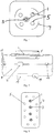
- FIG 3 shows an arrangement in which the UV apparatus includes a plurality of tubes 1.
- the tubes 1 are arranged in parallel in a substantially straight line array, but other configurations are possible.
- Each tube is provided with a core 3 and a plurality of lamps 5 are arranged around the array of tubes (although, if desired the lamps could also be arranged within the array of tubes).
- the lamps 5 are surrounded by a single reflector 7 in the form of a reflective inner surface of a container for the apparatus, although again a different reflector arrangement can be used if desired.
- the tubes 1 may be connected either in series or in parallel, either to maximise the disinfecting effect or to maximise throughput.
- FIG 4 shows an apparatus which is particularly useful where the liquid is especially optically dense.
- two tubes 1 are arranged in parallel (although more than two tubes may be so arranged of desired) and are provided with valves 21, 23 at each end.
- Valves 21 provided at the inlet of the tubes 1 may be solenoid valves and operate to allow liquid to enter one of the tubes at a time.
- Valves 23 provided at the outlet of each of the tubes 1 are non-return valves and serve to prevent treated liquid flowing back through either of the tubes.
- the two tubes are operated sequentially, with each tube emptying in turn to reveal the catalyst to the UV light. Once the core 3 has been exposed to the required dose of UV light, the valves 21 are switched so that the liquid flows through the tube with the active catalyst.
- the cycle time may be, for example, from 1 to 15 minutes.
- Figures 5, 6 and 7 show an apparatus in which photocatalytic beads may additionally be introduced into, and removed from, the liquid being treated.
- the apparatus includes a valve 25 for introducing beads into a bead flow circuit and a pump 27 for circulating the beads through the tube 1.
- the beads may be of ceramic, plastics or metal and may incorporate or be coated with the same or a different photocatalyst as that used in conjunction with the core 3.
- the beads provide additional sites for the generation of free radicals and assist in maintaining the inner surface of the tube 1 clean, while preferably circulating only in a limited part of the apparatus.
- the beads 29 may be introduced upstream of the inlet to the tube 1 by way of a Venturi arrangement 31 and may be removed from the liquid downstream of the outlet of the tube, by way of a slanting grid 33 which is dimensioned to restrain and divert the beads back to the pump 27.
- means may be provided for injecting a chemical, such as hydrogen peroxide, into the fluid stream.
- a chemical such as hydrogen peroxide
- the chemical under the influence of the UV lamps, increases the density of aggressive chemical radicals in the fluid stream. This can be of particular use in the treatment of waste water to reduce Carbon Oxygen Demand (COD) and Biological Oxygen Demand (BOD).
- the apparatus according to the present invention is particularly useful in the control of bacteria in metalworking fluids, cloudy water, and in sensitive environmental areas such as open sea drilling.
Landscapes
- Chemical & Material Sciences (AREA)
- Water Supply & Treatment (AREA)
- Life Sciences & Earth Sciences (AREA)
- Hydrology & Water Resources (AREA)
- Engineering & Computer Science (AREA)
- Environmental & Geological Engineering (AREA)
- Organic Chemistry (AREA)
- Health & Medical Sciences (AREA)
- Toxicology (AREA)
- Chemical Kinetics & Catalysis (AREA)
- Physical Water Treatments (AREA)
- Catalysts (AREA)
- Treatment Of Water By Oxidation Or Reduction (AREA)
- Physical Or Chemical Processes And Apparatus (AREA)
Claims (14)
- Appareil à UV comprenant : un tube (1) de matériau transparent aux UV ; au moins une lampe à UV (5) fournie extérieurement au tube de manière à émettre une lumière UV vers le tube ; et un coeur (3) s'étendant dans un sens axial à l'intérieur du tube, le coeur (3) ayant la forme d'une bobine à inversions de sens de telle sorte qu'un liquide passant à travers le tube tourne de manière alternée dans un sens anti-horaire puis dans un sens horaire, caractérisé en ce que les inversions de sens de la bobine créent une série de vortex de turbulence massive présentant ainsi continûment différentes parties du liquide au niveau de la surface interne du tube et en ce qu'un photocatalyseur est fourni sur au moins une surface du coeur et est réactif à la lumière UV émise par la lampe pour générer des radicaux libres dans le liquide passant à travers le tube.
- Appareil à UV selon la revendication 1, dans lequel le coeur (3) a la forme d'une bobine ouverte à inversions de sens pour perturber l'écoulement du liquide sans restreindre l'écoulement.
- Appareil à UV selon la revendication 1, dans lequel le coeur (3) est une bobine hélicoïdale solide à inversions de sens permettant néanmoins une superficie en coupe transversale libre suffisante pour des débits d'écoulement élevés de liquide, par exemple la bobine hélicoïdale solide peut être un simple ressort hélicoïdal ou une bobine solide en plastique, béton ou métal.
- Appareil à UV selon n'importe quelle revendication précédente, dans lequel le sens de la bobine est inversé à chaque révolution complète.
- Appareil à UV selon n'importe quelle revendication précédente, dans lequel le catalyseur comprend du dioxyde de titane et/ou de l'oxyde de zinc, par exemple du dioxyde de titane sous forme de dioxyde de titane nanocristallin (anatase).
- Appareil à UV selon n'importe quelle revendication précédente, dans lequel un moyen est fourni de telle sorte que l'écoulement de liquide à travers le tube (1) soit intermittent, par exemple pulsé.
- Appareil à UV selon n'importe quelle revendication précédente, dans lequel un clapet anti-retour (13) est fourni pour empêcher le liquide d'entrer à nouveau dans une entrée du tube (1).
- Appareil à UV selon n'importe quelle revendication précédente, dans lequel une vanne (15), telle qu'une électrovanne, est fournie pour diriger le liquide sortant du tube (1) de retour vers une source de liquide potentiellement contaminé ou vers une source de liquide de nettoyage destinée à recevoir un liquide traité.
- Appareil à UV selon la revendication 8, dans lequel un moyen (19), tel qu'une pompe, est fourni pour circuler un fluide de nettoyage, par exemple incorporant des particules abrasives, à travers le tube (1).
- Appareil à UV selon n'importe quelle revendication précédente et comportant une pluralité de tubes (1).
- Appareil à UV selon la revendication 10, dans lequel deux ou plusieurs tubes (1) sont disposés en parallèle et sont dotés de vannes (21, 23) à chaque extrémité de manière à isoler les tubes les uns des autres, par exemple des vannes (21) fournies à l'entrée des tubes (1) peuvent être des électrovannes et peuvent fonctionner pour permettre au liquide d'entrer dans l'un des tubes à la fois et/ou des vannes (23) fournies à la sortie de chacun des tubes (1) peuvent être des clapets anti-retour et peuvent servir à empêcher le liquide de refluer à travers l'un quelconque des tubes.
- Appareil à UV selon n'importe quelle revendication précédente, dans lequel un moyen (25, 31) est fourni pour introduire des billes photocatalytiques (29) dans le liquide en cours de traitement, par exemple sous forme d'un agencement Venturi (31) fourni pour introduire les billes (29) en amont du ou de chaque tube (1).
- Appareil à UV selon la revendication 12, dans lequel un moyen (33) est en outre fourni pour retirer de telles billes photocatalytiques (29), par exemple sous forme d'une grille inclinée (33) fournie en aval du ou de chaque tube (1).
- Appareil à UV selon n'importe quelle revendication précédente, dans lequel un moyen est fourni pour injecter un produit chimique, tel que du peroxyde d'hydrogène, dans le flux de fluide.
Applications Claiming Priority (2)
| Application Number | Priority Date | Filing Date | Title |
|---|---|---|---|
| GBGB1302035.9A GB201302035D0 (en) | 2013-02-05 | 2013-02-05 | UV Apparatus |
| PCT/EP2014/052268 WO2014122185A1 (fr) | 2013-02-05 | 2014-02-05 | Appareil à uv |
Publications (2)
| Publication Number | Publication Date |
|---|---|
| EP2953902A1 EP2953902A1 (fr) | 2015-12-16 |
| EP2953902B1 true EP2953902B1 (fr) | 2019-05-08 |
Family
ID=47988751
Family Applications (1)
| Application Number | Title | Priority Date | Filing Date |
|---|---|---|---|
| EP14703069.6A Active EP2953902B1 (fr) | 2013-02-05 | 2014-02-05 | Appareil à uv |
Country Status (7)
| Country | Link |
|---|---|
| US (2) | US20160016830A1 (fr) |
| EP (1) | EP2953902B1 (fr) |
| AU (1) | AU2014214056B2 (fr) |
| ES (1) | ES2740999T3 (fr) |
| GB (3) | GB201302035D0 (fr) |
| WO (1) | WO2014122185A1 (fr) |
| ZA (1) | ZA201505517B (fr) |
Families Citing this family (4)
| Publication number | Priority date | Publication date | Assignee | Title |
|---|---|---|---|---|
| FR3048242B1 (fr) * | 2016-02-26 | 2020-12-18 | Maf Agrobotic | Convoyeur hydraulique d'objets flottants equipe d'un dispositif d'assainissement de composition de convoyage, installation equipee d'un tel convoyeur et procede d'assainissement |
| US10293597B2 (en) * | 2017-02-16 | 2019-05-21 | Shibaura Mechatronics Corporation | Tablet printing apparatus |
| US11952293B2 (en) | 2019-03-07 | 2024-04-09 | International Water-Guard Industries Inc. | Apparatus for disinfecting a fluid |
| DE102021106740A1 (de) * | 2021-03-18 | 2022-09-22 | Heinrich Schäffler | Desinfektionsvorrichtung |
Citations (3)
| Publication number | Priority date | Publication date | Assignee | Title |
|---|---|---|---|---|
| US5069885A (en) * | 1990-04-23 | 1991-12-03 | Ritchie David G | Photocatalytic fluid purification apparatus having helical nontransparent substrate |
| WO2000020045A1 (fr) * | 1998-10-02 | 2000-04-13 | Common Services Agency | Dispositif pour traitement de liquides biologiques |
| US20020172627A1 (en) * | 2001-03-16 | 2002-11-21 | Akira Aoyagi | System for decomposing harmful substances by using photocatalyst |
Family Cites Families (16)
| Publication number | Priority date | Publication date | Assignee | Title |
|---|---|---|---|---|
| US4466741A (en) * | 1982-01-16 | 1984-08-21 | Hisao Kojima | Mixing element and motionless mixer |
| US5043080A (en) * | 1990-02-26 | 1991-08-27 | Solarchem Enterprises Inc. | Treating contaminated effluents and groundwaters |
| US5790934A (en) * | 1996-10-25 | 1998-08-04 | E. Heller & Company | Apparatus for photocatalytic fluid purification |
| JP3902304B2 (ja) * | 1997-12-24 | 2007-04-04 | 昇 阪野 | 紫外線照射装置 |
| DE10216477B4 (de) * | 2002-04-13 | 2006-01-19 | Liedy, Werner, Prof. Dr.-Ing. | Neue Reaktor- und Verfahrenskonzepte zur technischen Anwendung der Photokatalyse |
| US7090779B2 (en) * | 2003-10-20 | 2006-08-15 | Lawrence Allen Bernstein | Manually operable water purifying device |
| SE526461C2 (sv) * | 2003-12-19 | 2005-09-20 | Kurt Andersson | Blandningsanordning för blandning av luft och vatten i en vattenrenare |
| US7540167B2 (en) * | 2004-07-08 | 2009-06-02 | Dean Murphy | Condensed water production system |
| US20090145855A1 (en) * | 2007-12-06 | 2009-06-11 | Novapure Systems Inc. | Water Purifier System and Method |
| FR2935908B1 (fr) * | 2008-09-12 | 2011-01-14 | Centre Nat Rech Scient | Photocatalyseurs a base de mousses tridimentionnelles structurees en carbure et notamment en beta-sic |
| US20100224562A1 (en) * | 2009-03-05 | 2010-09-09 | Rolchigo Philip M | Ultraviolet Disinfection System and Method |
| US8980178B2 (en) * | 2009-05-23 | 2015-03-17 | Sensor Electronic Technology, Inc. | Medium treatment using ultraviolet light |
| KR20110043247A (ko) * | 2009-10-21 | 2011-04-27 | (주)아리에코 | 수처리 장치 |
| GB201004443D0 (en) * | 2010-03-17 | 2010-05-05 | Catalysystems Ltd | Photocatalytic reactor and methods of use |
| CA2833601A1 (fr) * | 2011-04-20 | 2012-10-26 | Soane Energy, Llc | Traitement des eaux usees |
| US20140048470A1 (en) * | 2012-08-15 | 2014-02-20 | Encotech, Inc. | System for Treating Water From Induced Hydraulic Fracturing |
-
2013
- 2013-02-05 GB GBGB1302035.9A patent/GB201302035D0/en not_active Ceased
-
2014
- 2014-02-05 EP EP14703069.6A patent/EP2953902B1/fr active Active
- 2014-02-05 US US14/392,065 patent/US20160016830A1/en not_active Abandoned
- 2014-02-05 GB GB1514899.2A patent/GB2525360B/en not_active Expired - Fee Related
- 2014-02-05 WO PCT/EP2014/052268 patent/WO2014122185A1/fr not_active Ceased
- 2014-02-05 AU AU2014214056A patent/AU2014214056B2/en not_active Ceased
- 2014-02-05 ES ES14703069T patent/ES2740999T3/es active Active
-
2015
- 2015-07-31 ZA ZA2015/05517A patent/ZA201505517B/en unknown
-
2016
- 2016-02-22 GB GBGB1603031.4A patent/GB201603031D0/en not_active Ceased
-
2018
- 2018-07-27 US US16/048,112 patent/US20180334400A1/en not_active Abandoned
Patent Citations (3)
| Publication number | Priority date | Publication date | Assignee | Title |
|---|---|---|---|---|
| US5069885A (en) * | 1990-04-23 | 1991-12-03 | Ritchie David G | Photocatalytic fluid purification apparatus having helical nontransparent substrate |
| WO2000020045A1 (fr) * | 1998-10-02 | 2000-04-13 | Common Services Agency | Dispositif pour traitement de liquides biologiques |
| US20020172627A1 (en) * | 2001-03-16 | 2002-11-21 | Akira Aoyagi | System for decomposing harmful substances by using photocatalyst |
Also Published As
| Publication number | Publication date |
|---|---|
| US20180334400A1 (en) | 2018-11-22 |
| ZA201505517B (en) | 2016-10-26 |
| AU2014214056A1 (en) | 2015-09-10 |
| GB201514899D0 (en) | 2015-10-07 |
| EP2953902A1 (fr) | 2015-12-16 |
| GB201603031D0 (en) | 2016-04-06 |
| WO2014122185A1 (fr) | 2014-08-14 |
| GB2525360A (en) | 2015-10-21 |
| GB2525360B (en) | 2016-03-30 |
| AU2014214056B2 (en) | 2017-07-27 |
| US20160016830A1 (en) | 2016-01-21 |
| ES2740999T3 (es) | 2020-02-07 |
| GB201302035D0 (en) | 2013-03-20 |
Similar Documents
| Publication | Publication Date | Title |
|---|---|---|
| US10570029B2 (en) | System for treating liquids by applying ultra-violet radiation | |
| US6403030B1 (en) | Ultraviolet wastewater disinfection system and method | |
| US8506886B2 (en) | Ultraviolet photoreactor for the purification of fluids | |
| US20060108293A1 (en) | Method and apparatus for liquid purification | |
| US20180334400A1 (en) | Uv apparatus | |
| JP5559340B2 (ja) | 紫外線照射死角領域を除去した紫外線を利用した殺菌浄化装置 | |
| KR100718676B1 (ko) | 광촉매 비드체를 이용한 수질살균정화장치 | |
| CN106536421B (zh) | 用于液体净化装置的照射室、净化装置和饮料分配器 | |
| WO2008113128A1 (fr) | Procédé et appareil permettant d'effectuer une transformation prédéterminée | |
| CN205045844U (zh) | 一种紫外光催化强氧化饮用水的处理装置 | |
| CA2961429A1 (fr) | Reacteur a lumiere uv destine aux fluides contamines | |
| KR102256064B1 (ko) | 오존가스를 병용한 자외선 수질 정화장치 | |
| JP3858734B2 (ja) | 水処理装置 | |
| US20160176727A1 (en) | Apparatus for uv disinfection of a liquid | |
| WO2023091062A1 (fr) | Système de traitement de fluides avec lampe à rayonnement uv à l'intérieur d'un réacteur | |
| JP5799197B2 (ja) | バラスト水処理装置 | |
| KR101416067B1 (ko) | Uv 반사부재를 구비한 반응조 및 펄스 uv를 이용한 수처리장치 | |
| KR101584164B1 (ko) | 펄스 uv를 이용한 수처리장치 | |
| JP7624229B2 (ja) | 液体浄化装置 | |
| EP3015435A1 (fr) | Dispositif de réduction de la contamination microbienne des eaux usées sans réactifs | |
| US20130313105A1 (en) | Method and Device for Treating Opaque Fluids with UV Radiation | |
| JP2014151300A (ja) | 水処理用紫外線照射装置およびバラスト水処理装置 |
Legal Events
| Date | Code | Title | Description |
|---|---|---|---|
| PUAI | Public reference made under article 153(3) epc to a published international application that has entered the european phase |
Free format text: ORIGINAL CODE: 0009012 |
|
| 17P | Request for examination filed |
Effective date: 20150819 |
|
| AK | Designated contracting states |
Kind code of ref document: A1 Designated state(s): AL AT BE BG CH CY CZ DE DK EE ES FI FR GB GR HR HU IE IS IT LI LT LU LV MC MK MT NL NO PL PT RO RS SE SI SK SM TR |
|
| AX | Request for extension of the european patent |
Extension state: BA ME |
|
| RIN1 | Information on inventor provided before grant (corrected) |
Inventor name: THEAKER, DAVID NIGEL Inventor name: GUMMER, EDWARD CHRISTOPHER |
|
| RIN1 | Information on inventor provided before grant (corrected) |
Inventor name: GUMMER, EDWARD CHRISTOPHER Inventor name: THEAKER, DAVID NIGEL |
|
| DAX | Request for extension of the european patent (deleted) | ||
| RBV | Designated contracting states (corrected) |
Designated state(s): AL AT BE BG CH CY CZ DE DK EE ES FI FR GR HR HU IE IS IT LI LT LU LV MC MK MT NL NO PL PT RO RS SE SI SK SM TR |
|
| STAA | Information on the status of an ep patent application or granted ep patent |
Free format text: STATUS: EXAMINATION IS IN PROGRESS |
|
| 17Q | First examination report despatched |
Effective date: 20170616 |
|
| GRAP | Despatch of communication of intention to grant a patent |
Free format text: ORIGINAL CODE: EPIDOSNIGR1 |
|
| STAA | Information on the status of an ep patent application or granted ep patent |
Free format text: STATUS: GRANT OF PATENT IS INTENDED |
|
| INTG | Intention to grant announced |
Effective date: 20181221 |
|
| GRAS | Grant fee paid |
Free format text: ORIGINAL CODE: EPIDOSNIGR3 |
|
| GRAA | (expected) grant |
Free format text: ORIGINAL CODE: 0009210 |
|
| STAA | Information on the status of an ep patent application or granted ep patent |
Free format text: STATUS: THE PATENT HAS BEEN GRANTED |
|
| AK | Designated contracting states |
Kind code of ref document: B1 Designated state(s): AL AT BE BG CH CY CZ DE DK EE ES FI FR GR HR HU IE IS IT LI LT LU LV MC MK MT NL NO PL PT RO RS SE SI SK SM TR |
|
| REG | Reference to a national code |
Ref country code: CH Ref legal event code: EP Ref country code: AT Ref legal event code: REF Ref document number: 1129867 Country of ref document: AT Kind code of ref document: T Effective date: 20190515 |
|
| REG | Reference to a national code |
Ref country code: DE Ref legal event code: R096 Ref document number: 602014046202 Country of ref document: DE Ref country code: IE Ref legal event code: FG4D |
|
| REG | Reference to a national code |
Ref country code: NL Ref legal event code: MP Effective date: 20190508 |
|
| REG | Reference to a national code |
Ref country code: LT Ref legal event code: MG4D |
|
| PG25 | Lapsed in a contracting state [announced via postgrant information from national office to epo] |
Ref country code: AL Free format text: LAPSE BECAUSE OF FAILURE TO SUBMIT A TRANSLATION OF THE DESCRIPTION OR TO PAY THE FEE WITHIN THE PRESCRIBED TIME-LIMIT Effective date: 20190508 Ref country code: PT Free format text: LAPSE BECAUSE OF FAILURE TO SUBMIT A TRANSLATION OF THE DESCRIPTION OR TO PAY THE FEE WITHIN THE PRESCRIBED TIME-LIMIT Effective date: 20190908 Ref country code: SE Free format text: LAPSE BECAUSE OF FAILURE TO SUBMIT A TRANSLATION OF THE DESCRIPTION OR TO PAY THE FEE WITHIN THE PRESCRIBED TIME-LIMIT Effective date: 20190508 Ref country code: FI Free format text: LAPSE BECAUSE OF FAILURE TO SUBMIT A TRANSLATION OF THE DESCRIPTION OR TO PAY THE FEE WITHIN THE PRESCRIBED TIME-LIMIT Effective date: 20190508 Ref country code: NO Free format text: LAPSE BECAUSE OF FAILURE TO SUBMIT A TRANSLATION OF THE DESCRIPTION OR TO PAY THE FEE WITHIN THE PRESCRIBED TIME-LIMIT Effective date: 20190808 Ref country code: NL Free format text: LAPSE BECAUSE OF FAILURE TO SUBMIT A TRANSLATION OF THE DESCRIPTION OR TO PAY THE FEE WITHIN THE PRESCRIBED TIME-LIMIT Effective date: 20190508 Ref country code: HR Free format text: LAPSE BECAUSE OF FAILURE TO SUBMIT A TRANSLATION OF THE DESCRIPTION OR TO PAY THE FEE WITHIN THE PRESCRIBED TIME-LIMIT Effective date: 20190508 Ref country code: LT Free format text: LAPSE BECAUSE OF FAILURE TO SUBMIT A TRANSLATION OF THE DESCRIPTION OR TO PAY THE FEE WITHIN THE PRESCRIBED TIME-LIMIT Effective date: 20190508 |
|
| PG25 | Lapsed in a contracting state [announced via postgrant information from national office to epo] |
Ref country code: RS Free format text: LAPSE BECAUSE OF FAILURE TO SUBMIT A TRANSLATION OF THE DESCRIPTION OR TO PAY THE FEE WITHIN THE PRESCRIBED TIME-LIMIT Effective date: 20190508 Ref country code: BG Free format text: LAPSE BECAUSE OF FAILURE TO SUBMIT A TRANSLATION OF THE DESCRIPTION OR TO PAY THE FEE WITHIN THE PRESCRIBED TIME-LIMIT Effective date: 20190808 Ref country code: GR Free format text: LAPSE BECAUSE OF FAILURE TO SUBMIT A TRANSLATION OF THE DESCRIPTION OR TO PAY THE FEE WITHIN THE PRESCRIBED TIME-LIMIT Effective date: 20190809 Ref country code: LV Free format text: LAPSE BECAUSE OF FAILURE TO SUBMIT A TRANSLATION OF THE DESCRIPTION OR TO PAY THE FEE WITHIN THE PRESCRIBED TIME-LIMIT Effective date: 20190508 |
|
| REG | Reference to a national code |
Ref country code: AT Ref legal event code: MK05 Ref document number: 1129867 Country of ref document: AT Kind code of ref document: T Effective date: 20190508 |
|
| PG25 | Lapsed in a contracting state [announced via postgrant information from national office to epo] |
Ref country code: CZ Free format text: LAPSE BECAUSE OF FAILURE TO SUBMIT A TRANSLATION OF THE DESCRIPTION OR TO PAY THE FEE WITHIN THE PRESCRIBED TIME-LIMIT Effective date: 20190508 Ref country code: DK Free format text: LAPSE BECAUSE OF FAILURE TO SUBMIT A TRANSLATION OF THE DESCRIPTION OR TO PAY THE FEE WITHIN THE PRESCRIBED TIME-LIMIT Effective date: 20190508 Ref country code: AT Free format text: LAPSE BECAUSE OF FAILURE TO SUBMIT A TRANSLATION OF THE DESCRIPTION OR TO PAY THE FEE WITHIN THE PRESCRIBED TIME-LIMIT Effective date: 20190508 Ref country code: RO Free format text: LAPSE BECAUSE OF FAILURE TO SUBMIT A TRANSLATION OF THE DESCRIPTION OR TO PAY THE FEE WITHIN THE PRESCRIBED TIME-LIMIT Effective date: 20190508 Ref country code: EE Free format text: LAPSE BECAUSE OF FAILURE TO SUBMIT A TRANSLATION OF THE DESCRIPTION OR TO PAY THE FEE WITHIN THE PRESCRIBED TIME-LIMIT Effective date: 20190508 Ref country code: SK Free format text: LAPSE BECAUSE OF FAILURE TO SUBMIT A TRANSLATION OF THE DESCRIPTION OR TO PAY THE FEE WITHIN THE PRESCRIBED TIME-LIMIT Effective date: 20190508 |
|
| REG | Reference to a national code |
Ref country code: ES Ref legal event code: FG2A Ref document number: 2740999 Country of ref document: ES Kind code of ref document: T3 Effective date: 20200207 |
|
| REG | Reference to a national code |
Ref country code: DE Ref legal event code: R097 Ref document number: 602014046202 Country of ref document: DE |
|
| PG25 | Lapsed in a contracting state [announced via postgrant information from national office to epo] |
Ref country code: SM Free format text: LAPSE BECAUSE OF FAILURE TO SUBMIT A TRANSLATION OF THE DESCRIPTION OR TO PAY THE FEE WITHIN THE PRESCRIBED TIME-LIMIT Effective date: 20190508 |
|
| PLBE | No opposition filed within time limit |
Free format text: ORIGINAL CODE: 0009261 |
|
| STAA | Information on the status of an ep patent application or granted ep patent |
Free format text: STATUS: NO OPPOSITION FILED WITHIN TIME LIMIT |
|
| PG25 | Lapsed in a contracting state [announced via postgrant information from national office to epo] |
Ref country code: TR Free format text: LAPSE BECAUSE OF FAILURE TO SUBMIT A TRANSLATION OF THE DESCRIPTION OR TO PAY THE FEE WITHIN THE PRESCRIBED TIME-LIMIT Effective date: 20190508 |
|
| 26N | No opposition filed |
Effective date: 20200211 |
|
| PG25 | Lapsed in a contracting state [announced via postgrant information from national office to epo] |
Ref country code: PL Free format text: LAPSE BECAUSE OF FAILURE TO SUBMIT A TRANSLATION OF THE DESCRIPTION OR TO PAY THE FEE WITHIN THE PRESCRIBED TIME-LIMIT Effective date: 20190508 |
|
| PG25 | Lapsed in a contracting state [announced via postgrant information from national office to epo] |
Ref country code: SI Free format text: LAPSE BECAUSE OF FAILURE TO SUBMIT A TRANSLATION OF THE DESCRIPTION OR TO PAY THE FEE WITHIN THE PRESCRIBED TIME-LIMIT Effective date: 20190508 |
|
| REG | Reference to a national code |
Ref country code: CH Ref legal event code: PL |
|
| REG | Reference to a national code |
Ref country code: BE Ref legal event code: MM Effective date: 20200229 |
|
| PG25 | Lapsed in a contracting state [announced via postgrant information from national office to epo] |
Ref country code: LU Free format text: LAPSE BECAUSE OF NON-PAYMENT OF DUE FEES Effective date: 20200205 Ref country code: MC Free format text: LAPSE BECAUSE OF FAILURE TO SUBMIT A TRANSLATION OF THE DESCRIPTION OR TO PAY THE FEE WITHIN THE PRESCRIBED TIME-LIMIT Effective date: 20190508 |
|
| PG25 | Lapsed in a contracting state [announced via postgrant information from national office to epo] |
Ref country code: CH Free format text: LAPSE BECAUSE OF NON-PAYMENT OF DUE FEES Effective date: 20200229 Ref country code: LI Free format text: LAPSE BECAUSE OF NON-PAYMENT OF DUE FEES Effective date: 20200229 |
|
| PG25 | Lapsed in a contracting state [announced via postgrant information from national office to epo] |
Ref country code: IE Free format text: LAPSE BECAUSE OF NON-PAYMENT OF DUE FEES Effective date: 20200205 |
|
| PG25 | Lapsed in a contracting state [announced via postgrant information from national office to epo] |
Ref country code: BE Free format text: LAPSE BECAUSE OF NON-PAYMENT OF DUE FEES Effective date: 20200229 |
|
| PG25 | Lapsed in a contracting state [announced via postgrant information from national office to epo] |
Ref country code: MT Free format text: LAPSE BECAUSE OF FAILURE TO SUBMIT A TRANSLATION OF THE DESCRIPTION OR TO PAY THE FEE WITHIN THE PRESCRIBED TIME-LIMIT Effective date: 20190508 Ref country code: CY Free format text: LAPSE BECAUSE OF FAILURE TO SUBMIT A TRANSLATION OF THE DESCRIPTION OR TO PAY THE FEE WITHIN THE PRESCRIBED TIME-LIMIT Effective date: 20190508 |
|
| PG25 | Lapsed in a contracting state [announced via postgrant information from national office to epo] |
Ref country code: MK Free format text: LAPSE BECAUSE OF FAILURE TO SUBMIT A TRANSLATION OF THE DESCRIPTION OR TO PAY THE FEE WITHIN THE PRESCRIBED TIME-LIMIT Effective date: 20190508 Ref country code: IS Free format text: LAPSE BECAUSE OF FAILURE TO SUBMIT A TRANSLATION OF THE DESCRIPTION OR TO PAY THE FEE WITHIN THE PRESCRIBED TIME-LIMIT Effective date: 20190908 |
|
| PGFP | Annual fee paid to national office [announced via postgrant information from national office to epo] |
Ref country code: FR Payment date: 20230220 Year of fee payment: 10 Ref country code: ES Payment date: 20230307 Year of fee payment: 10 |
|
| PGFP | Annual fee paid to national office [announced via postgrant information from national office to epo] |
Ref country code: IT Payment date: 20230222 Year of fee payment: 10 Ref country code: DE Payment date: 20230221 Year of fee payment: 10 |
|
| REG | Reference to a national code |
Ref country code: DE Ref legal event code: R119 Ref document number: 602014046202 Country of ref document: DE |
|
| PG25 | Lapsed in a contracting state [announced via postgrant information from national office to epo] |
Ref country code: DE Free format text: LAPSE BECAUSE OF NON-PAYMENT OF DUE FEES Effective date: 20240903 |
|
| PG25 | Lapsed in a contracting state [announced via postgrant information from national office to epo] |
Ref country code: FR Free format text: LAPSE BECAUSE OF NON-PAYMENT OF DUE FEES Effective date: 20240229 |
|
| PG25 | Lapsed in a contracting state [announced via postgrant information from national office to epo] |
Ref country code: FR Free format text: LAPSE BECAUSE OF NON-PAYMENT OF DUE FEES Effective date: 20240229 Ref country code: DE Free format text: LAPSE BECAUSE OF NON-PAYMENT OF DUE FEES Effective date: 20240903 |
|
| PG25 | Lapsed in a contracting state [announced via postgrant information from national office to epo] |
Ref country code: IT Free format text: LAPSE BECAUSE OF NON-PAYMENT OF DUE FEES Effective date: 20240205 |
|
| REG | Reference to a national code |
Ref country code: ES Ref legal event code: FD2A Effective date: 20250327 |
|
| PG25 | Lapsed in a contracting state [announced via postgrant information from national office to epo] |
Ref country code: ES Free format text: LAPSE BECAUSE OF NON-PAYMENT OF DUE FEES Effective date: 20240206 |