EP2954155B1 - Procédé de calcul de charges sur un composant sous-marin - Google Patents
Procédé de calcul de charges sur un composant sous-marin Download PDFInfo
- Publication number
- EP2954155B1 EP2954155B1 EP13780361.5A EP13780361A EP2954155B1 EP 2954155 B1 EP2954155 B1 EP 2954155B1 EP 13780361 A EP13780361 A EP 13780361A EP 2954155 B1 EP2954155 B1 EP 2954155B1
- Authority
- EP
- European Patent Office
- Prior art keywords
- riser
- section
- forces
- subsea
- measuring
- Prior art date
- Legal status (The legal status is an assumption and is not a legal conclusion. Google has not performed a legal analysis and makes no representation as to the accuracy of the status listed.)
- Active
Links
Images


Classifications
-
- E—FIXED CONSTRUCTIONS
- E21—EARTH OR ROCK DRILLING; MINING
- E21B—EARTH OR ROCK DRILLING; OBTAINING OIL, GAS, WATER, SOLUBLE OR MELTABLE MATERIALS OR A SLURRY OF MINERALS FROM WELLS
- E21B41/00—Equipment or details not covered by groups E21B15/00 - E21B40/00
- E21B41/0007—Equipment or details not covered by groups E21B15/00 - E21B40/00 for underwater installations
Definitions
- the invention relates to a method and an associated system of estimating loads on a subsea component, such as a wellhead system, a subsea tree, an emergency disconnect package and or a lower riser package, based on measurements performed in at least two positions/sections in the lower part of the riser.
- a subsea component such as a wellhead system, a subsea tree, an emergency disconnect package and or a lower riser package, based on measurements performed in at least two positions/sections in the lower part of the riser.
- the invention is specifically applicable for offshore applications.
- C/WO riser systems Small bored and thick walled open sea completion and workover (C/WO) riser systems are currently extensively used to provide well access for performing C/WO operations on subsea oil and gas wells.
- the riser connects the surface vessel, or any other floating arrangement, to the wellhead system (WH) and subsea tree (XT) at the sea bottom.
- WH wellhead system
- XT subsea tree
- LRP lower riser package
- EDP emergency disconnect package
- the weight of the LRP and EDP are substantial.
- waves may cause significant rig motion.
- dynamic loads are applied to the riser, and loads may be transferred to the WH.
- the riser is also exposed to loads both from waves and sea current. Even though open sea risers are flexible and can be exposed to large elastic deformations, loads applied on the EDP, LRP, XT and WH can be high. In the event of an accidental drive-off or drift-off of the rig, the equipment may be damaged.
- a structural analysis shall be performed in order to verify the adequacy of the riser design.
- the structural analysis is based on a number of assumptions regarding particularly the environmental conditions. In order to ensure safe operations, assumptions are generally conservative in nature, and as a consequence, operating windows tend to be quite narrow. Furthermore, estimates of fatigue damage may also be very high, and as a result riser system components or XTs may have to be replaced more frequently than would have been necessary if more accurate load estimates were available. Wells may also have to be abandoned much earlier if conservative assumptions are adopted.
- Prior art solutions include riser monitoring systems (RMS) that provide more accurate information on the loads applied to the riser.
- RMS riser monitoring systems
- One such system measures loads on the lower tapered stress joint (LTSJ) as well as on the tension joint above and below the rucker tension wire (RTW) ring. Loads are then estimated for the rest of the riser by using a numerical finite element model simulating the behavior of the physical system.
- Another riser monitoring system measures the displacement and inclination at a number of positions along the riser. For this system a numerical model is used to provide load estimates.
- a third system includes strain gauge sensors mounted on a special spool piece positioned in the riser stack and a method for estimating loads in the riser using measurement data and a finite element model.
- the measured or estimated loads must also be carefully monitored and compared to estimates of fatigue life. It is an objective of the present invention to establish a method and system for providing estimates of the loads on the WH, XT, EDP, LRP and possible other components of the subsea system. Furthermore, it is also an objective of the present invention to use the estimates obtained by this method and system to assist in positioning a surface vessel in an optimal way in order to minimize loads on the WH and thereby optimize the fatigue life of the WH.
- a riser is extending from a surface vessel, or any other floating arrangement, to the wellhead (WH).
- a lower tapered stress joint (LTSJ) may be arranged in the lower part of the riser.
- the LTSJ may optionally be connected to the WH via an EDP, LRP and XT.
- the LTSJ is provided with at least two measuring devices in two positions/sections A and B measuring section forces (tension/bending moment) and/ or inclination/ displacement.
- the EDP/ LRP is provided with an inclination/ acceleration measurement device in position/section C.
- the terms 'position' and 'section' shall be understood as a location where measurements are made, i.e. a cross-section of the riser/subsea component of interest.
- the relationship between measurements performed by the measuring devices in positions A and B at the LTSJ and in position E on the EDP/LRP, and the forces acting on any given point on the subsea component (EDP, LRP, XT, WH) can be established using a model that includes both the effect of section forces in positions A or B and, if necessary, EDP/ LRP inertia and gravity forces.
- the calculations may in a first embodiment be made by assuming that the subsea component is in equilibrium. Alternatively, in a second embodiment, in case inertia forces cannot be disregarded, a more complex dynamic solution is found.
- measuring device shall be understood in a broad sense throughout the disclosure, and that other terms may be used in the same meaning, including strain gauges or similar sensors for measuring section forces or inclination, inclinometer, accelerometer, velocity measurements, displacement measurement or temperature sensors.
- section force may include bending and torsion moments, tension and shear forces.
- the strain gauges or similar measuring devices may be located in at least at two positions A and B at the lower part of the riser, preferably at the lower tapered stress joint that forms part of the riser.
- the strain gauges or similar sensors are constructed to produce estimates of tension, bending moments and or inclination at the respective positions.
- the strain measurements can be used to obtain estimates of tension forces, shear forces and bending moments at respective locations.
- strain sensors are used in three positions, e.g. position A, B and C, and inclinometers and/ or accelerometers is used in two other positions, e.g. positions D and E.
- strain gauges are arranged in a spaced-apart relationship around the outer circumference of the LTSJ with a 90 degrees spacing. Bending moments along two perpendicular axes can be obtained in addition to tension load. In the case of the tension load, replicate estimates will be obtained for the said sensor configuration. Generally, the number of independent measurements shall be greater than the number of sought responses in order to allow for redundancy in sensor design.
- strain gauges By positioning strain gauges at an inclination relative to the main axis of the riser, information about additional load components can be obtained. Internal pressure and torsion loading are assessed by placing sensors fully or partly in the circumferential direction.
- Thermal effects must also be considered, especially if the riser contains a fluid at a higher temperature than the surroundings. This may involve the additional use of dedicated temperature sensors such as thermocouples positioned at the location of strain measurement or at one or several locations directly in conjunction with the measurement or with the fluid contained inside the riser.
- the fluid temperature may also be monitored using existing temperature sensors in the control system.
- the effect of temperature on strain/tension measurement may be simulated and removed using thermo-mechanic models evaluating thermal expansion and measured results.
- Inclinometers can be used to measure the inclination of the LTSJ or EDP/LRP at any point on the stack. Some inclinometers are also capable of measuring velocities and accelerations at the very same points. Translational and rotational velocities and accelerations may be considered. Velocities and accelerations are of importance when considering the dynamics of the subsea components. Dynamic loading may have to be considered when assessing loads if the subsea component has a large mass and accelerates at a sufficiently high rate. The inertia forces are evaluated by calculating the mass times the acceleration of the component.
- equilibrium equations can be used to calculate forces in the stack from section A-B in the lower part of the riser, e.g. a section in the LTSJ, downwards through the equipment connected to the LTSJ, such as EDP, LRP, XT, and to the WH.
- Independent estimates may be obtained from one or more sensor/measuring devices arrangements, including a sufficient number of independent sensor measurements.
- One possible configuration/arrangement involves two set of sensors for measuring longitudinal strains at locations A and B. Estimates of bending moments for sections A and B may be used to estimate corresponding shear forces.
- V A M A ⁇ M B L AB
- M A is the bending moment in measuring position A
- M B is the bending moment in measuring position B
- L AB is the effective distance between measuring positions A and B.
- the distance L AB should be minimized. However, if the distance is made too small errors in bending force estimates M A and M B may be significant compared to the difference in bending moment M A -M B .
- the optimal distance L AB can only be determined if the accuracy of measuring devices are known as well as the load range. The distance L AB can normally be between 0.2 - 2 meters depending on the dimensions of the risers and external load.
- more sensors/ measuring devices and measurement points along the LTSJ may be introduced. If the bending moments applied to the LTSJ are high, errors in M A and M B are small compared to the difference M A -M B .
- the distance L AB can be made small. However, if load levels are generally low, the distance L AB should be made large in order to make the difference M A -M B large.
- a measuring position C is introduced to allow for accurate measurements when the load levels are low. For low loading levels, sensors A and C are activated, and for high load levels, sensors A and B are activated.
- the measurement system will determine which set of sensors/measuring devices to use by evaluating load levels and errors in the measurements. It is of course possible to introduce more sensors/ measuring devices in order to be able to perform measurements for a larger range of bending moments.
- Estimates of shear forces can also be obtained from sensors/ measuring devices positioned at locations A, B or C by positioning a sufficient number of strain gauges to allow unique determination of all load components such as tension, bending, torsion, shear and internal pressure. For each position there are six independent section force components to consider in addition to the internal pressure, i.e. altogether 18 variables for the three cross sections plus pressure. However, the tension can be regarded to differ only slightly for all sections, and changes in pressure can be estimated by considering the mass of the section between sensor/ measuring positions. Torsion loads can also be regarded as equal for all sections. As a result, there are only 15 independent variables which can be assessed by performing a minimum of 15 independent measurements. Strain sensor sets in positions A and B may be replaced by sensor sets in positions D and E.
- the sensor sets in positions D and E should include inclinometers and tension sensors measuring the deformation of the LTSJ.
- Measurement position E acts as a reference for bending of the LTSJ.
- E Young's modulus
- I the stiffness of the section
- ⁇ D the inclination of the riser at position D relative to the LTSJ axis at the lowermost section or the EDP.
- ⁇ is a characteristic length which can be expressed as:
- T is the riser tension force which may either be measured by a set of strain gauges (A or B) or deduced from readings from the rig riser tensioner system and mass calculations. Since it is known that the shear force in any section is the derivative of the bending moment, the shear force V(z) can also be found to be:
- Estimates of bending moments for any section of the LTSJ can also be obtained in the case that the LTSJ has a non-uniform or tapered cross section.
- the load distribution can be calculated numerically.
- the estimates of shear forces at position A, or any other lower position on the LTSJ may be used in combination with measurement of tension forces and bending moments to assess tension forces, shear forces and bending moments at different sections in the stack and wellhead. It has been demonstrated that in most cases inertia forces can be disregarded, and that estimates of forces at any given cross-section of the stack can be obtained by considering only the equilibrium for the part between the cross section and measurement point A on the LTSJ.
- L AW is the length of the section extending from the lowermost measurement point on the LTSJ to the wellhead top (WH top).
- Tension forces at cross-sections W or Z can be obtained assessing tension in measurement point A and subtracting the net down weight of the intermediate section. For this simplified case tension does not affect bending moments at the wellhead.
- a more complete and accurate calculation of loads on the wellhead can be obtained by considering the deformation of the LTSJ and stack.
- a finite element model for the stack from the wellhead up to the section A on the LTSJ can be established.
- the model can be solved using actual section forces in cross-section A.
- the results will be the shape of the deformed stack and LTSJ and the section forces in any cross-section of the stack including the WH.
- a closed form solution can be developed by considering force equilibrium with tension forces in section A acting in a direction deviating from the vertical due to the deformation of the stack and, if applicable, wellhead inclination.
- T W , V W and M W are the effective tension, shear force and bending moment at the wellhead.
- T A , V A and M A are the effective tension, shear force and bending moment at the tension at cross-section A.
- ⁇ is the average inclination of the lower stack, and ⁇ is the inclination of the riser at section A, both with respect to the vertical.
- G S is the gravitational force of the stack acting in the vertical direction.
- L A is the displacement of cross-section A from the vertical line going through the wellhead.
- L G is the distance from the WH datum to the center of gravity of the entire lower stack along the axis of the lower stack.
- L S is the distance from the wellhead to the top of the lower stack along the axis of the lower stack.
- L J is the distance from the top of the lower stack to cross-section A along the axis of the lower stack. Distances L A and L J must be estimated by assessing the deformation of the LTSJ exposed to a set of section forces in A, for instance using equation (2).
- Verification or more accurate estimates of forces can be obtained by assessing the measured data from the inclinometer positioned on the stack, position E.
- the inclinometer will reveal whether the stack and wellhead are tilted and whether a net bending moment is applied as a result of the weight of the stack acting in a direction non-parallel to the wellhead axis. Furthermore, the inclinometer also reveals whether dynamic effects should be considered, and gives input to the on-line calculation of these effects.
- Mass forces acting on the stack can be calculated by multiplying the mass and acceleration of the stack. By directly measuring the acceleration of the stack the loads can be established. In the case that the movement of the wellhead is one of rotation around a reference point in the well, the moment of inertia must be considered (this is described in the second embodiment below). In most cases movement of the stack is limited, and inertia forces are of lesser importance. This also applies for hydrodynamic loading.
- inertia of the subsea stack may be considered, in which case inertia terms must be introduced in equations 6 and 7 (or alternatively equations 8, 9 and 10).
- I W is the moment of inertia about the point W and ⁇ is the angular velocity around the same point.
- the time derivative is calculated. Angular velocities and accelerations can be measured and input into the equation making assessment of resulting forces and bending moments simpler.
- the equation is deduced exclusively for the two-dimensional plane. Establishment of fully three-dimensional equations can be performed in a similar manner as demonstrated for the two-dimensional case.
- both inclination and section force measurements may be combined to give estimates of shear force continuously along the LTSJ with greater accuracy than by the simplified equilibrium evaluation. Calculations then take into consideration the actual shape of the bent section of the LTSJ. Given that the accuracy of force and inclination measurements are of similar relative accuracy, improved estimates of forces acting on the system will be obtained by calibrating the system by means of both sets of independent measurements. Increased redundancy will also be obtained. Mass forces for the LTSJ may also be taken into account as the accelerations of the riser are measured directly, but the effects of such forces on results are small.
- the invention describes a system and method of measuring loads and deformation on the lower part of the riser, e.g. at the lower tapered stress joint (LTSJ), and, based on these measurements, calculate an estimate for the loads at any position on a subsea component.
- the subsea component can be any component typically in place subsea, such as WH, EDP, LRP and or XT. It is a need that the content of the riser is known. If the riser is filled with a fluid, the density and temperature of the fluid must be known. This is necessary in order to properly estimate the tension in the system. If the riser contains a wireline or drill string, mass balance calculations are also performed in order to make sure that the level of tension is correct. The stiffness of the riser joint may also have to be re-evaluated.
- the stiffness of the well does not need be known in order to estimate the forces applied on the wellhead from measurement of section forces and inclinations on the LTSJ.
- the stiffness of the well is an important parameter in the global riser model which can be used to check results and to estimate forces at cross-sections further up in the riser. Hence, estimation of the WH stiffness is important for the purposes of verification.
- the measurement set-up can be used for estimating wellhead stiffness.
- the wellhead stiffness depends on the quality of the cementing, the soil properties and interactions with the template structure. It is very difficult to measure the stiffness of the well directly in other ways due to limited access.
- independent verification of the method for estimating loads on the stack and WH is performed by introducing for example strain gauges at sections of the stack. If new XTs are installed these can be instrumented. Sensors or measuring devices are then preferably permanent. If special adapters are used to connect LRP and XT, such adapters may constitute beneficial positions for positioning of sensors. There may be several possible positions for mounting a sensor package for the purposes of verification. It should be pointed out that such a measurement is not a requirement for the invention. The method is known to be of high accuracy, and there are other methods also for validating results.
- the invention relates to a method for estimating section forces including bending moments on a subsea component, the subsea component being connected to a riser and a well, wherein the method comprises the steps of;
- the distance between the lower (A) and the upper (B) sections is between 0.2 and 2.0 meters.
- the method further comprises the step of measuring the inclination in at least one position (A, B, C, E) in the lower part of the riser.
- the method is performed using the assumptions that inertia forces can be neglected.
- the method is performed using the assumptions that gravitational forces can be neglected.
- the method is performed using the assumptions that both gravitational and inertia forces can be neglected.
- the estimation of shear force components in a lower section A of the lower riser by assuming equilibrium for the part of the riser between the first upper section B and the lower section A, said shear force components set equal to the difference between the bending moment components for said sections A, B divided by the distance between the sections.
- the estimation of shear force components in a lower section A of the lower riser s performed by assuming equilibrium for the part of the riser between a second upper section C, a first upper section B and the lower section A, said shear force components set equal to either the difference between the bending moment components for said sections A and C divided by the distance between the sections or the difference between the bending moment components for said sections A and B divided by the distance between the sections.
- the distance between the closest sensor sections may be within 0.5 m and 2.0 meters.
- the method comprises the calculation of the force components acting in any section Z of the subsea component by assuming that the components of shear force acting in a lower section A of the riser, and that the bending moment components for any section Z of the subsea component equals the measured bending moment component at a section A of the riser plus the shear force at section A times a distance between the said section A of the riser and the said section Z of the subsea component.
- a riser deformation angle is measured in two sections A, B, C or D and the shape and load distribution of the riser is calculated assuming that the lower part of the riser deforms elastically.
- the riser may be exposed to a known tension, which tension may be known because it is either measured or estimated.
- the subsea component may comprise a wellhead, a subsea tree, an emergency disconnect package and or a lower riser package.
- the first measuring device may in an aspect be a strain gauge and the second measuring device may be a strain gauge.
- the first measuring device may in one aspect be a strain gauge and the second measuring device may be an inclinometer.
- the first measuring device and the second measuring device are adapted to measure strain, bending moment and or shear force.
- strain gauges or similar sensors for measuring section forces can either be attached permanently to the riser joint or mounted in a non-permanent way. In latter case sensors may be attached to the riser prior to operations or they may be attached during operations, for example by a remote operated vehicle (ROV) operating subsea.
- ROV remote operated vehicle
- the estimates of shear forces can also be obtained from sensors positioned at sections A, B or C by positioning a sufficient number of strain gauges to allow unique determination of all load components (tension, bending, torsion, shear and internal pressure). There are seven independent section force components including bending moments in total to be measured and at least seven independent measurements are needed to evaluate the shear force.
- the inclinometers may be attached to the riser and a part of the subsea package (EDP/LRP) or to the well completion (XT/WH). Inclinometers may be placed at the same sections as strain sensors or between strain sensors. Furthermore, several inclinometers may also be attached to the lower part of the riser. This will increase the cost and complexity of the system, but will give both greater accuracy and redundancy. In addition it will allow a more exact measurement of external forces such as drag from the sea current. Sensors may be mounted both in a permanent or a non-permanent manner. In the latter case, the systems can be mounted prior to operation or during operations.
- the inclinometers may measure the movement/rotation with the corresponding velocities along three axes. By comparing the inclination of the riser at one or several positions with the inclination of the lower stack, it is possible to obtain an independent estimate of the bending loads on the LTSJ and stack.
- the inclinometers may be placed in a section E at the subsea component or at the lowermost part of the riser and at a position D at the top of the LTSJ of the lower riser. This allows for calculating estimates of the dynamic movement of the subsea component and compensation for dynamic effects through the inclusion of an inertia term. In combination with loads, this allows for evaluation of the lateral stiffness of the well.
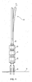
- FIG. 1 shows schematically a typical configuration of a lower stack and wellhead.
- a riser, or riser string, 1 extends from a surface vessel (not shown) to a subsea wellhead 6, the wellhead 6 forming the entry to a well in the subsea formation 7.
- the riser 1 is connected to the wellhead 6 via a wellhead stack, comprising an emergency disconnect package (EDP) 3, a lower riser package (LRP) 4, a subsea tree adapter (XT adapter) and a subsea tree (XT) 5.
- EDP emergency disconnect package
- LRP lower riser package
- XT adapter subsea tree adapter
- XT subsea tree
- LTSJ Lower Tapered Stress Joint
- Figure 2 shows possible positions of inclinometers and strain gauge sensors on the lower tapered stress joint and stack.
- two inclinometers are arranged at positions D and E, while strain gauges are arranged at positions A, B and V.
- Three sensors (A, B, D) have been placed on the LTSJ 2.
- Positions E and V are at the stack.
- Position D need not necessarily be above positions A and B.
- Inclinometers may be placed at the same positions as the strain sensors or between the strain sensors.
- Position V also functions as a validation point for the measurements in positions A and B.
- L AB refers to the length L between the two neighboring sensors A and B.
- Figure 3 shows an embodiment of the system of figure 2 where there are arranged four sensors on the LTSJ 2 at positions A, B, C and D.
- L AB refers to the length L between the two neighboring sensors A and B
- L BC refers to the length L between positions B and C.
- Figure 4 shows the system of figure 3 , but in this figure the riser string 1, LTSJ 2 and stack are deformed, shown by the bent riser string and riser tension T.
- An additional strain sensor is arranged at position W at the stack (on the wellhead).
- Figure 5 shows typical shear stress distributions V and bending moment distribution M in the LTSJ 2 and stack at different locations along the stack, LTSJ 2 and riser string 1.
- Figure 6 shows the load equilibrium of a section of the LTSJ between bending moment sensor distributions A and B.
- the riser is assumed to be un-deformed.
- T A is the tension force in position A
- V A is here a corresponding shear force component
- M A is a corresponding bending moment component.
- W AB is the weight of section of the pipe between positions A and B.
- L AB is the distance between positions A and B.
- Figure 7 shows the deformation of the LTSJ and the system for measuring the angle.
- Two inclinometers D and E measure the inclination of the system at positions D, ⁇ D , and E, ⁇ E , respectively.
- T A refers to the tension at position A
- V A refers to a shear force component at position A
- M A refers to a bending moment component at position A.
- M B and T B refers to a bending moment component and the tension at position B, respectively.
- W AB is the weight of the LTSJ section between positions A and B.
- Figure 8 shows the equilibrium of the entire stack (including XT) and the main parameters included in the estimation of section force components T W , V W and M W on the wellhead.
- M DLTSJ is the mass of the lower part of the LTSJ.
- the weights of the EDP, LRP, adapter and XT are given as W EDP , W LRP , W ADPT, W XT , respectively.
- Figure 9 shows an embodiment of Figure 8 , but in this embodiment is not including the loads on the XT.
- Figure 9 shows the equilibrium of the stack above the XT and the main parameters included in the estimation of the loads on the XT re-entry hub.
- Figure 10 shows a system for evaluating utilization of the lower stack (shown above wellhead 6) taking into consideration the position of the rig 11, motion, waves and wind (collective term 12), and current.
- the riser 1 is extending from the rig 11 to the wellhead 6 and is shown being influenced by wave, current, wind motions etc. Data (via lines 13) may be transferred directly on-shore (not shown)(10).
- Figure 11 shows the positioning of the rig as a part of a calibration pattern test to determine the system response and to establish an operating window.
- the rig is anchored by anchors (dotted lines 15).
- a Z indicates an acceptable operating area
- P AZ indicates a possibly acceptable operating area
- N AZ indicates a not acceptable operating area of the position of the rig 11 relative the position of the wellhead 6.
- Figure 12 shows a system for assessing and using input data from a multitude of sensors to estimate loads on the stack and to evaluate errors in estimates.
- the figure is an example and only considers a simplified system with a LTSJ with constant stiffness.
- the invention is herein described in non-limiting embodiments. A person skilled in the art will understand that there may be made alterations and modifications to the embodiments that are within the scope of the invention as described in the attached claims. For example, if used in an advisory mode it is important that the output produced by the RMS is quality assured.
- the proposed invention can, if properly qualified and within certain limits, be regarded as a safety critical system. First, it is designed with a sufficient redundancy. Sensors on the LTSJ assess a number of strain components and do not only allow for the estimation of bending loads, but also the assessment of errors in estimation. The tension in the riser system is not a completely independent variable.
- Tension is measured by sensors placed higher on the risers (usually by strain gauges close to the tension joint) and by the tensioner system of the rig.
- the tension at the LTSJ is equal to the tension at a higher point in the system minus the net weight for the part of the riser separating the measurement points.
- sensors measure tension at two or more closely spaced positions on the LTSJ, and differences in tension measurements can be expected to be very small. If tension measurements can be verified to be correct, a quality check has also been performed for the bending moment measurements since estimates are determined from the same set of sensors. A further verification of bending moment readings can be obtained by comparing the results from several sensors. However, bending moment measurements can also be checked and calibrated by independent means. First, prior to use measurements can be independently checked and calibrated by controlled bending of the LTSJ under a known load. Second, during use a function test and calibration can be performed by moving the rig in a predefined pattern in order to bend the LTSJ with sensors.
Landscapes
- Life Sciences & Earth Sciences (AREA)
- Engineering & Computer Science (AREA)
- Geology (AREA)
- Mining & Mineral Resources (AREA)
- Physics & Mathematics (AREA)
- Environmental & Geological Engineering (AREA)
- Fluid Mechanics (AREA)
- General Life Sciences & Earth Sciences (AREA)
- Geochemistry & Mineralogy (AREA)
- Earth Drilling (AREA)
- Testing Of Balance (AREA)
Claims (15)
- Procédé d'estimation de forces de section incluant des moments de flexion sur un composant sous-marin, le composant sous-marin (3, 4, 5, 6) étant raccordé à une colonne montante (1) et un puits, caractérisé en ce que le procédé comprend les étapes de :- mesure de forces de section et/ou déformations dans une section inférieure (A) et une première section supérieure (B) au niveau de la partie inférieure de la colonne montante (1) par l'utilisation d'au moins deux dispositifs de mesure indépendants,- mesure de l'inclinaison et de l'accélération du composant sous-marin (3, 4, 5, 6) à l'aide d'un jeu de capteurs placés dans un emplacement du composant sous-marin (section E),- calcul des forces de section pour toute section (Z) du composant sous-marin (3, 4, 5, 6) par l'utilisation d'un dispositif de traitement adapté pour recevoir des données en provenance desdits dispositifs de mesure et effectuer des calculs, les calculs impliquant :∘ une évaluation d'équilibre dynamique pour le composant sous-marin (3, 4, 5, 6) et la partie de la colonne montante en dessous de la section inférieure (A) incluant des termes de charge,∘ la prise en considération de la grandeur et de la directionnalité de forces de section dans la section (A), et∘ des forces de gravité et d'inertie pour le composant sous-marin (3, 4, 5, 6) d'après lesdites mesures.
- Procédé selon la revendication 1, dans lequel l'inclinaison est mesurée dans au moins une position (A, B, C, E) de la partie inférieure de la colonne montante (1).
- Procédé selon la revendication 1, dans lequel les composantes de force de cisaillement dans une section inférieure (A) de la partie inférieure de la colonne montante (1) sont calculées en supposant un équilibre de forces et de moments pour la partie de la colonne montante (1) entre la première section supérieure (B) et la section inférieure (A), lesdites composantes de force de cisaillement étant fixées égales à la différence entre les composantes de moment de flexion pour lesdites sections (A, B) divisée par la distance entre les sections.
- Procédé selon la revendication 1, dans lequel les composantes de force de cisaillement dans une section inférieure (A) de la partie inférieure de la colonne montante (1) sont calculées en supposant un équilibre de forces et de moments pour la partie de la colonne montante (1) entre une seconde section supérieure (C), la première section supérieure (B) et la section inférieure (A), lesdites composantes de force de cisaillement étant fixées égales soit à la différence entre les composantes de moment de flexion pour lesdites sections (A, C) divisée par la distance entre les sections soit à la différence entre les composantes de moment de flexion pour lesdites sections (A, B) divisée par la distance entre les sections.
- Procédé selon la revendication 1, dans lequel les composantes de force agissant dans toute section (Z) du composant sous-marin (3, 4, 5, 6) sont calculées en supposant que les composantes de force de cisaillement agissent dans la section inférieure (A) de la colonne montante (1), et que les composantes de moment de flexion pour toute section (Z) du composant sous-marin (3, 4, 5, 6) sont égales à la composante de moment de flexion mesurée au niveau d'une section (A) de la colonne montante (1) plus la force de cisaillement au niveau de la section (A) fois une distance entre ladite section (A) de la colonne montante (1) et ladite section (Z) du composant sous-marin (3, 4, 5, 6).
- Procédé selon la revendication 1, dans lequel un angle de déformation de colonne montante est mesuré dans deux sections (A, B, C, D) et la distribution de forme et de charge de la colonne montante (1) est calculée en supposant que la partie inférieure de la colonne montante (1) se déforme élastiquement.
- Procédé selon la revendication 1, dans lequel le premier dispositif de mesure et le second dispositif de mesure sont adaptés pour mesurer un effort, un moment de flexion et/ou une force de cisaillement.
- Procédé selon la revendication 1, dans lequel le dispositif de mesure dans la section inférieure (A) est un jeu de trois extensomètres ou plus et le dispositif de mesure dans la première section supérieure (B) est un jeu de trois extensomètres ou plus.
- Procédé selon la revendication 1, dans lequel le dispositif de mesure dans la section inférieure (A) est un ensemble de trois extensomètres ou plus et le dispositif de mesure dans la première section supérieure (B) est un inclinomètre.
- Procédé selon la revendication 1, dans lequel le dispositif de mesure dans la section inférieure (A) est un inclinomètre et le dispositif de mesure dans la première section supérieure (B) est un jeu de trois extensomètres ou plus.
- Procédé selon la revendication 1, dans lequel les extensomètres ou capteurs similaires pour mesurer des forces de section peuvent être soit fixés de façon permanente au joint de colonne montante soit montés de façon non permanente de sorte que des capteurs puissent être fixés à la colonne montante (1) avant des opérations ou pendant des opérations, comme un véhicule téléguidé (ROV) opérant sous la mer.
- Procédé selon la revendication 1, dans lequel les inclinomètres peuvent être fixés à la colonne montante (1) et une partie de l'ensemble sous-marin (EDP (3)/LRP (4)) ou à la complétion de puits (XT (5) /WH (6)), ou dans une section sur le composant sous-marin (3, 4, 5, 6) ou au niveau de la partie la plus basse de la colonne montante (1) et dans une position au-dessus du LTSJ (2) de la partie inférieure de la colonne montante (1).
- Procédé selon la revendication 1, dans lequel un angle de déformation de colonne montante est calculé en deux positions et la distribution de forme et de charge de la colonne montante (1) est calculée en supposant que le LTSJ (2) se déforme élastiquement et est exposé à une tension donnée.
- Procédé selon l'une quelconque des revendications précédentes, dans lequel le procédé comprend l'étape de mesure de l'inclinaison dans au moins une position sur le composant sous-marin (3, 4, 5, 6) ou sur la partie inférieure de la colonne montante (1).
- Procédé selon la revendication 1, dans lequel les mesures d'inclinaison et d'accélération sont de préférence mesurées au centre de gravité du composant sous-marin (3, 4, 5, 6).
Applications Claiming Priority (2)
| Application Number | Priority Date | Filing Date | Title |
|---|---|---|---|
| NO20121242 | 2012-10-24 | ||
| PCT/EP2013/072262 WO2014064190A2 (fr) | 2012-10-24 | 2013-10-24 | Procédé de calcul de charges sur un composant sous-marin |
Publications (2)
| Publication Number | Publication Date |
|---|---|
| EP2954155A2 EP2954155A2 (fr) | 2015-12-16 |
| EP2954155B1 true EP2954155B1 (fr) | 2017-06-21 |
Family
ID=49484281
Family Applications (1)
| Application Number | Title | Priority Date | Filing Date |
|---|---|---|---|
| EP13780361.5A Active EP2954155B1 (fr) | 2012-10-24 | 2013-10-24 | Procédé de calcul de charges sur un composant sous-marin |
Country Status (2)
| Country | Link |
|---|---|
| EP (1) | EP2954155B1 (fr) |
| WO (1) | WO2014064190A2 (fr) |
Cited By (1)
| Publication number | Priority date | Publication date | Assignee | Title |
|---|---|---|---|---|
| WO2019067765A1 (fr) * | 2017-09-29 | 2019-04-04 | Bp Corporation North America Inc. | Systèmes et procédés de surveillance des composants d'un système de puits |
Families Citing this family (8)
| Publication number | Priority date | Publication date | Assignee | Title |
|---|---|---|---|---|
| NO341582B1 (en) * | 2015-04-14 | 2017-12-11 | 4Subsea As | System og metode for å overvåke utmatting ved brønnhodet i undervannsbrønner |
| GB201506496D0 (en) | 2015-04-16 | 2015-06-03 | Expro North Sea Ltd | Measurement system and methods |
| NO342377B1 (en) * | 2015-06-24 | 2018-05-14 | 4Subsea As | Method for determining wellhead fatigue |
| US9593568B1 (en) * | 2015-10-09 | 2017-03-14 | General Electric Company | System for estimating fatigue damage |
| GB2550192A (en) * | 2016-05-12 | 2017-11-15 | Xodus Group Ltd | Pipework Fatigue Lifetime Measurement |
| US11492893B2 (en) | 2017-05-30 | 2022-11-08 | The Texas A&M University System | Apparatus and method for predicting a deformed shape of a structure |
| NO343738B1 (en) * | 2017-06-07 | 2019-05-27 | 4Subsea As | Method for establishing an estimate of bending moment over time in a subsea well and an article of manufacture |
| GB2597978B (en) | 2020-08-13 | 2023-01-25 | Aker Solutions As | Method of monitoring the loading of a subsea production system |
Family Cites Families (4)
| Publication number | Priority date | Publication date | Assignee | Title |
|---|---|---|---|---|
| FR2840951B1 (fr) * | 2002-06-13 | 2004-12-24 | Inst Francais Du Petrole | Ensemble d'instrumentation d'une colonne montante de forage offshore |
| US20050100414A1 (en) * | 2003-11-07 | 2005-05-12 | Conocophillips Company | Composite riser with integrity monitoring apparatus and method |
| GB2428099B (en) * | 2004-03-22 | 2008-05-07 | Vetco Aibel As | A method and a device for monitoring and/or controlling a load on a tensioned elongated element |
| US7328741B2 (en) * | 2004-09-28 | 2008-02-12 | Vetco Gray Inc. | System for sensing riser motion |
-
2013
- 2013-10-24 EP EP13780361.5A patent/EP2954155B1/fr active Active
- 2013-10-24 WO PCT/EP2013/072262 patent/WO2014064190A2/fr not_active Ceased
Non-Patent Citations (1)
| Title |
|---|
| RUSSO M ET AL: "Fatigue Assessment of Subsea Wells for Future and Historical Operations Based on Measured Riser Loads", PROCEEDINGS OF THE ASME 2012. 31ST INTERNATIONAL CONFERENCE ON OCEAN, OFFSHORE AND ARCTIC ENGINEERING; OMAE 2012, RIO DE JANEIRO, BRAZIL, JULY 1-6, 2012, ASME, vol. 1, no. Paper No. OMAE2012-83162, 1 July 2012 (2012-07-01), pages 139 - 150, XP008170033, ISBN: 978-0-7918-4488-5, DOI: 10.1115/OMAE2012-83162 * |
Cited By (2)
| Publication number | Priority date | Publication date | Assignee | Title |
|---|---|---|---|---|
| WO2019067765A1 (fr) * | 2017-09-29 | 2019-04-04 | Bp Corporation North America Inc. | Systèmes et procédés de surveillance des composants d'un système de puits |
| US11261722B2 (en) | 2017-09-29 | 2022-03-01 | Bp Corporation North America Inc. | Systems and methods for monitoring components of a well |
Also Published As
| Publication number | Publication date |
|---|---|
| WO2014064190A2 (fr) | 2014-05-01 |
| WO2014064190A3 (fr) | 2014-08-28 |
| EP2954155A2 (fr) | 2015-12-16 |
Similar Documents
| Publication | Publication Date | Title |
|---|---|---|
| EP2954155B1 (fr) | Procédé de calcul de charges sur un composant sous-marin | |
| EP2886788B1 (fr) | Contrôle de fatigue de colonne montante | |
| US11034418B2 (en) | System and method for fuel savings and safe operation of marine structure | |
| EP2616786B1 (fr) | Procédé de détermination dans la tension d'un câble d'amarrage | |
| CN106574487B (zh) | 包括海下声学监测平台的海洋立管管理系统及关联方法 | |
| RU2640324C2 (ru) | Калибровка моделирования бурения, включая оценку растяжения и скручивания бурильной колонны | |
| JP6463028B2 (ja) | 浮体施設の荷重・応力モニタリング方法及び浮体施設の荷重・応力モニタリングシステム | |
| US20250326472A1 (en) | Apparatus and method for a real-time-monitoring of a riser and mooring of floating platforms | |
| Kim et al. | Real-time estimation of riser's deformed shape using inclinometers and Extended Kalman Filter | |
| Wu et al. | Design, implementation and analysis of full coupled monitoring system of FPSO with soft yoke mooring system | |
| US11585170B2 (en) | Flow meter measurement for drilling rig | |
| EP2811111A1 (fr) | Procédé et dispositif pour mesurer la pression exercée par un matériau terrestre | |
| US8188882B2 (en) | Depth measurement by distributed sensors | |
| US10378331B2 (en) | Monitoring integrity of a riser pipe network | |
| Mercan et al. | Soil Model Assessment for Subsea Wellhead Fatigue Using Monitoring Data | |
| MX2011011468A (es) | Modelo de choque producido por perforacion de pozo. | |
| KR101719510B1 (ko) | 심해 구조물의 안전성을 평가하는 방법 및 시스템 | |
| Ge et al. | Recent improvements in subsea wellhead fatigue monitoring algorithm and accuracy using verification and calibration techniques | |
| Choi et al. | Development of a new methodology for riser deformed shape prediction/monitoring | |
| Agarwal et al. | Validation of Global Riser/Wellhead Analysis using Data from a Full-scale Measurement Campaign | |
| KR20200023663A (ko) | 딥러닝을 이용한 해양 부유식 구조물의 계류선 손상 탐지 방법 | |
| Authen et al. | Reliable, low footprint and cost-effective monitoring of wellhead loads using autonomous IMUs for fatigue estimates | |
| Guzzo et al. | Addressing the Pressing Needs of Offshore Ultra-Deepwater Floating Facilities and Risers: Near Real-Time Management System for Deepwater Drilling Risers | |
| Da Silva | Calibration of Numerical Model for Wellhead Fatigue Assessment Using Measured Data | |
| CN120293204A (zh) | 一种自感知转体监测系统及风险智能预测方法 |
Legal Events
| Date | Code | Title | Description |
|---|---|---|---|
| PUAI | Public reference made under article 153(3) epc to a published international application that has entered the european phase |
Free format text: ORIGINAL CODE: 0009012 |
|
| 17P | Request for examination filed |
Effective date: 20151014 |
|
| AK | Designated contracting states |
Kind code of ref document: A2 Designated state(s): AL AT BE BG CH CY CZ DE DK EE ES FI FR GB GR HR HU IE IS IT LI LT LU LV MC MK MT NL NO PL PT RO RS SE SI SK SM TR |
|
| AX | Request for extension of the european patent |
Extension state: BA ME |
|
| DAX | Request for extension of the european patent (deleted) | ||
| GRAP | Despatch of communication of intention to grant a patent |
Free format text: ORIGINAL CODE: EPIDOSNIGR1 |
|
| STAA | Information on the status of an ep patent application or granted ep patent |
Free format text: STATUS: GRANT OF PATENT IS INTENDED |
|
| INTG | Intention to grant announced |
Effective date: 20170207 |
|
| GRAS | Grant fee paid |
Free format text: ORIGINAL CODE: EPIDOSNIGR3 |
|
| GRAA | (expected) grant |
Free format text: ORIGINAL CODE: 0009210 |
|
| STAA | Information on the status of an ep patent application or granted ep patent |
Free format text: STATUS: THE PATENT HAS BEEN GRANTED |
|
| AK | Designated contracting states |
Kind code of ref document: B1 Designated state(s): AL AT BE BG CH CY CZ DE DK EE ES FI FR GB GR HR HU IE IS IT LI LT LU LV MC MK MT NL NO PL PT RO RS SE SI SK SM TR |
|
| REG | Reference to a national code |
Ref country code: GB Ref legal event code: FG4D |
|
| REG | Reference to a national code |
Ref country code: CH Ref legal event code: EP |
|
| REG | Reference to a national code |
Ref country code: IE Ref legal event code: FG4D |
|
| REG | Reference to a national code |
Ref country code: AT Ref legal event code: REF Ref document number: 903123 Country of ref document: AT Kind code of ref document: T Effective date: 20170715 |
|
| REG | Reference to a national code |
Ref country code: DE Ref legal event code: R096 Ref document number: 602013022608 Country of ref document: DE |
|
| REG | Reference to a national code |
Ref country code: NO Ref legal event code: T2 Effective date: 20170621 |
|
| REG | Reference to a national code |
Ref country code: FR Ref legal event code: PLFP Year of fee payment: 5 |
|
| REG | Reference to a national code |
Ref country code: NL Ref legal event code: MP Effective date: 20170621 |
|
| PG25 | Lapsed in a contracting state [announced via postgrant information from national office to epo] |
Ref country code: LT Free format text: LAPSE BECAUSE OF FAILURE TO SUBMIT A TRANSLATION OF THE DESCRIPTION OR TO PAY THE FEE WITHIN THE PRESCRIBED TIME-LIMIT Effective date: 20170621 Ref country code: GR Free format text: LAPSE BECAUSE OF FAILURE TO SUBMIT A TRANSLATION OF THE DESCRIPTION OR TO PAY THE FEE WITHIN THE PRESCRIBED TIME-LIMIT Effective date: 20170922 Ref country code: FI Free format text: LAPSE BECAUSE OF FAILURE TO SUBMIT A TRANSLATION OF THE DESCRIPTION OR TO PAY THE FEE WITHIN THE PRESCRIBED TIME-LIMIT Effective date: 20170621 Ref country code: HR Free format text: LAPSE BECAUSE OF FAILURE TO SUBMIT A TRANSLATION OF THE DESCRIPTION OR TO PAY THE FEE WITHIN THE PRESCRIBED TIME-LIMIT Effective date: 20170621 |
|
| REG | Reference to a national code |
Ref country code: LT Ref legal event code: MG4D |
|
| REG | Reference to a national code |
Ref country code: AT Ref legal event code: MK05 Ref document number: 903123 Country of ref document: AT Kind code of ref document: T Effective date: 20170621 |
|
| PG25 | Lapsed in a contracting state [announced via postgrant information from national office to epo] |
Ref country code: SE Free format text: LAPSE BECAUSE OF FAILURE TO SUBMIT A TRANSLATION OF THE DESCRIPTION OR TO PAY THE FEE WITHIN THE PRESCRIBED TIME-LIMIT Effective date: 20170621 Ref country code: NL Free format text: LAPSE BECAUSE OF FAILURE TO SUBMIT A TRANSLATION OF THE DESCRIPTION OR TO PAY THE FEE WITHIN THE PRESCRIBED TIME-LIMIT Effective date: 20170621 Ref country code: RS Free format text: LAPSE BECAUSE OF FAILURE TO SUBMIT A TRANSLATION OF THE DESCRIPTION OR TO PAY THE FEE WITHIN THE PRESCRIBED TIME-LIMIT Effective date: 20170621 Ref country code: LV Free format text: LAPSE BECAUSE OF FAILURE TO SUBMIT A TRANSLATION OF THE DESCRIPTION OR TO PAY THE FEE WITHIN THE PRESCRIBED TIME-LIMIT Effective date: 20170621 Ref country code: BG Free format text: LAPSE BECAUSE OF FAILURE TO SUBMIT A TRANSLATION OF THE DESCRIPTION OR TO PAY THE FEE WITHIN THE PRESCRIBED TIME-LIMIT Effective date: 20170921 |
|
| PG25 | Lapsed in a contracting state [announced via postgrant information from national office to epo] |
Ref country code: EE Free format text: LAPSE BECAUSE OF FAILURE TO SUBMIT A TRANSLATION OF THE DESCRIPTION OR TO PAY THE FEE WITHIN THE PRESCRIBED TIME-LIMIT Effective date: 20170621 Ref country code: CZ Free format text: LAPSE BECAUSE OF FAILURE TO SUBMIT A TRANSLATION OF THE DESCRIPTION OR TO PAY THE FEE WITHIN THE PRESCRIBED TIME-LIMIT Effective date: 20170621 Ref country code: AT Free format text: LAPSE BECAUSE OF FAILURE TO SUBMIT A TRANSLATION OF THE DESCRIPTION OR TO PAY THE FEE WITHIN THE PRESCRIBED TIME-LIMIT Effective date: 20170621 Ref country code: SK Free format text: LAPSE BECAUSE OF FAILURE TO SUBMIT A TRANSLATION OF THE DESCRIPTION OR TO PAY THE FEE WITHIN THE PRESCRIBED TIME-LIMIT Effective date: 20170621 Ref country code: RO Free format text: LAPSE BECAUSE OF FAILURE TO SUBMIT A TRANSLATION OF THE DESCRIPTION OR TO PAY THE FEE WITHIN THE PRESCRIBED TIME-LIMIT Effective date: 20170621 |
|
| PG25 | Lapsed in a contracting state [announced via postgrant information from national office to epo] |
Ref country code: ES Free format text: LAPSE BECAUSE OF FAILURE TO SUBMIT A TRANSLATION OF THE DESCRIPTION OR TO PAY THE FEE WITHIN THE PRESCRIBED TIME-LIMIT Effective date: 20170621 Ref country code: PL Free format text: LAPSE BECAUSE OF FAILURE TO SUBMIT A TRANSLATION OF THE DESCRIPTION OR TO PAY THE FEE WITHIN THE PRESCRIBED TIME-LIMIT Effective date: 20170621 Ref country code: SM Free format text: LAPSE BECAUSE OF FAILURE TO SUBMIT A TRANSLATION OF THE DESCRIPTION OR TO PAY THE FEE WITHIN THE PRESCRIBED TIME-LIMIT Effective date: 20170621 Ref country code: IS Free format text: LAPSE BECAUSE OF FAILURE TO SUBMIT A TRANSLATION OF THE DESCRIPTION OR TO PAY THE FEE WITHIN THE PRESCRIBED TIME-LIMIT Effective date: 20171021 |
|
| REG | Reference to a national code |
Ref country code: DE Ref legal event code: R097 Ref document number: 602013022608 Country of ref document: DE |
|
| PLBE | No opposition filed within time limit |
Free format text: ORIGINAL CODE: 0009261 |
|
| STAA | Information on the status of an ep patent application or granted ep patent |
Free format text: STATUS: NO OPPOSITION FILED WITHIN TIME LIMIT |
|
| PG25 | Lapsed in a contracting state [announced via postgrant information from national office to epo] |
Ref country code: DK Free format text: LAPSE BECAUSE OF FAILURE TO SUBMIT A TRANSLATION OF THE DESCRIPTION OR TO PAY THE FEE WITHIN THE PRESCRIBED TIME-LIMIT Effective date: 20170621 |
|
| REG | Reference to a national code |
Ref country code: DE Ref legal event code: R119 Ref document number: 602013022608 Country of ref document: DE |
|
| 26N | No opposition filed |
Effective date: 20180322 |
|
| PG25 | Lapsed in a contracting state [announced via postgrant information from national office to epo] |
Ref country code: MC Free format text: LAPSE BECAUSE OF FAILURE TO SUBMIT A TRANSLATION OF THE DESCRIPTION OR TO PAY THE FEE WITHIN THE PRESCRIBED TIME-LIMIT Effective date: 20170621 |
|
| REG | Reference to a national code |
Ref country code: CH Ref legal event code: PL |
|
| REG | Reference to a national code |
Ref country code: IE Ref legal event code: MM4A |
|
| PG25 | Lapsed in a contracting state [announced via postgrant information from national office to epo] |
Ref country code: LI Free format text: LAPSE BECAUSE OF NON-PAYMENT OF DUE FEES Effective date: 20171031 Ref country code: DE Free format text: LAPSE BECAUSE OF NON-PAYMENT OF DUE FEES Effective date: 20180501 Ref country code: LU Free format text: LAPSE BECAUSE OF NON-PAYMENT OF DUE FEES Effective date: 20171024 Ref country code: CH Free format text: LAPSE BECAUSE OF NON-PAYMENT OF DUE FEES Effective date: 20171031 |
|
| REG | Reference to a national code |
Ref country code: BE Ref legal event code: MM Effective date: 20171031 |
|
| PG25 | Lapsed in a contracting state [announced via postgrant information from national office to epo] |
Ref country code: SI Free format text: LAPSE BECAUSE OF FAILURE TO SUBMIT A TRANSLATION OF THE DESCRIPTION OR TO PAY THE FEE WITHIN THE PRESCRIBED TIME-LIMIT Effective date: 20170621 Ref country code: BE Free format text: LAPSE BECAUSE OF NON-PAYMENT OF DUE FEES Effective date: 20171031 |
|
| REG | Reference to a national code |
Ref country code: FR Ref legal event code: PLFP Year of fee payment: 6 |
|
| PG25 | Lapsed in a contracting state [announced via postgrant information from national office to epo] |
Ref country code: MT Free format text: LAPSE BECAUSE OF NON-PAYMENT OF DUE FEES Effective date: 20171024 |
|
| PG25 | Lapsed in a contracting state [announced via postgrant information from national office to epo] |
Ref country code: IE Free format text: LAPSE BECAUSE OF NON-PAYMENT OF DUE FEES Effective date: 20171024 |
|
| PG25 | Lapsed in a contracting state [announced via postgrant information from national office to epo] |
Ref country code: HU Free format text: LAPSE BECAUSE OF FAILURE TO SUBMIT A TRANSLATION OF THE DESCRIPTION OR TO PAY THE FEE WITHIN THE PRESCRIBED TIME-LIMIT; INVALID AB INITIO Effective date: 20131024 |
|
| PG25 | Lapsed in a contracting state [announced via postgrant information from national office to epo] |
Ref country code: CY Free format text: LAPSE BECAUSE OF FAILURE TO SUBMIT A TRANSLATION OF THE DESCRIPTION OR TO PAY THE FEE WITHIN THE PRESCRIBED TIME-LIMIT Effective date: 20170621 |
|
| PG25 | Lapsed in a contracting state [announced via postgrant information from national office to epo] |
Ref country code: MK Free format text: LAPSE BECAUSE OF FAILURE TO SUBMIT A TRANSLATION OF THE DESCRIPTION OR TO PAY THE FEE WITHIN THE PRESCRIBED TIME-LIMIT Effective date: 20170621 |
|
| PG25 | Lapsed in a contracting state [announced via postgrant information from national office to epo] |
Ref country code: TR Free format text: LAPSE BECAUSE OF FAILURE TO SUBMIT A TRANSLATION OF THE DESCRIPTION OR TO PAY THE FEE WITHIN THE PRESCRIBED TIME-LIMIT Effective date: 20170621 |
|
| PG25 | Lapsed in a contracting state [announced via postgrant information from national office to epo] |
Ref country code: PT Free format text: LAPSE BECAUSE OF FAILURE TO SUBMIT A TRANSLATION OF THE DESCRIPTION OR TO PAY THE FEE WITHIN THE PRESCRIBED TIME-LIMIT Effective date: 20170621 |
|
| PG25 | Lapsed in a contracting state [announced via postgrant information from national office to epo] |
Ref country code: AL Free format text: LAPSE BECAUSE OF FAILURE TO SUBMIT A TRANSLATION OF THE DESCRIPTION OR TO PAY THE FEE WITHIN THE PRESCRIBED TIME-LIMIT Effective date: 20170621 |
|
| P01 | Opt-out of the competence of the unified patent court (upc) registered |
Effective date: 20230523 |
|
| PGFP | Annual fee paid to national office [announced via postgrant information from national office to epo] |
Ref country code: GB Payment date: 20251023 Year of fee payment: 13 |
|
| PGFP | Annual fee paid to national office [announced via postgrant information from national office to epo] |
Ref country code: NO Payment date: 20250930 Year of fee payment: 13 |
|
| PGFP | Annual fee paid to national office [announced via postgrant information from national office to epo] |
Ref country code: IT Payment date: 20251008 Year of fee payment: 13 |
|
| PGFP | Annual fee paid to national office [announced via postgrant information from national office to epo] |
Ref country code: FR Payment date: 20251027 Year of fee payment: 13 |