EP2954249B1 - Dispositif de stockage et de distribution de fluides liquides et/ou gazeux sous pression et dispositif de conversion de l'énergie d'un carburant, et procédé de montage d'un dispositif de stockage et de distribution de fluides liquides et/ou gazeux sous pression - Google Patents
Dispositif de stockage et de distribution de fluides liquides et/ou gazeux sous pression et dispositif de conversion de l'énergie d'un carburant, et procédé de montage d'un dispositif de stockage et de distribution de fluides liquides et/ou gazeux sous pression Download PDFInfo
- Publication number
- EP2954249B1 EP2954249B1 EP14703538.0A EP14703538A EP2954249B1 EP 2954249 B1 EP2954249 B1 EP 2954249B1 EP 14703538 A EP14703538 A EP 14703538A EP 2954249 B1 EP2954249 B1 EP 2954249B1
- Authority
- EP
- European Patent Office
- Prior art keywords
- collar
- wall
- valve
- restoring
- restoring element
- Prior art date
- Legal status (The legal status is an assumption and is not a legal conclusion. Google has not performed a legal analysis and makes no representation as to the accuracy of the status listed.)
- Not-in-force
Links
- 239000007788 liquid Substances 0.000 title claims description 13
- 238000006243 chemical reaction Methods 0.000 title claims description 6
- 238000000034 method Methods 0.000 title claims description 6
- 238000003860 storage Methods 0.000 title claims 4
- 238000007789 sealing Methods 0.000 claims description 43
- 239000000463 material Substances 0.000 claims description 26
- 229920003023 plastic Polymers 0.000 claims description 25
- 239000004033 plastic Substances 0.000 claims description 25
- 238000003825 pressing Methods 0.000 claims description 20
- 239000000446 fuel Substances 0.000 claims description 16
- 230000005489 elastic deformation Effects 0.000 claims description 14
- 229920002647 polyamide Polymers 0.000 claims description 8
- 239000004952 Polyamide Substances 0.000 claims description 7
- 239000004703 cross-linked polyethylene Substances 0.000 claims description 7
- 229920003020 cross-linked polyethylene Polymers 0.000 claims description 7
- 238000006073 displacement reaction Methods 0.000 claims description 7
- 239000003638 chemical reducing agent Substances 0.000 claims description 6
- 238000004519 manufacturing process Methods 0.000 claims description 6
- 238000000071 blow moulding Methods 0.000 claims description 3
- 230000002787 reinforcement Effects 0.000 claims 1
- 238000007493 shaping process Methods 0.000 claims 1
- 238000011144 upstream manufacturing Methods 0.000 claims 1
- 230000006835 compression Effects 0.000 description 59
- 238000007906 compression Methods 0.000 description 59
- -1 Polyethylen Polymers 0.000 description 9
- 238000004132 cross linking Methods 0.000 description 7
- 230000015572 biosynthetic process Effects 0.000 description 6
- 238000005755 formation reaction Methods 0.000 description 6
- 229910052739 hydrogen Inorganic materials 0.000 description 6
- 239000001257 hydrogen Substances 0.000 description 6
- 229920000573 polyethylene Polymers 0.000 description 6
- 239000004698 Polyethylene Substances 0.000 description 5
- 230000000694 effects Effects 0.000 description 5
- 239000010410 layer Substances 0.000 description 5
- 230000003014 reinforcing effect Effects 0.000 description 5
- 230000008901 benefit Effects 0.000 description 4
- 150000002431 hydrogen Chemical class 0.000 description 4
- 229920001169 thermoplastic Polymers 0.000 description 4
- 239000012815 thermoplastic material Substances 0.000 description 4
- 241001295925 Gegenes Species 0.000 description 3
- 230000008859 change Effects 0.000 description 3
- 238000002788 crimping Methods 0.000 description 3
- 238000009432 framing Methods 0.000 description 3
- 239000004416 thermosoftening plastic Substances 0.000 description 3
- UFHFLCQGNIYNRP-UHFFFAOYSA-N Hydrogen Chemical compound [H][H] UFHFLCQGNIYNRP-UHFFFAOYSA-N 0.000 description 2
- 239000012790 adhesive layer Substances 0.000 description 2
- 229910052782 aluminium Inorganic materials 0.000 description 2
- XAGFODPZIPBFFR-UHFFFAOYSA-N aluminium Chemical compound [Al] XAGFODPZIPBFFR-UHFFFAOYSA-N 0.000 description 2
- 238000010276 construction Methods 0.000 description 2
- 229920001903 high density polyethylene Polymers 0.000 description 2
- 239000004700 high-density polyethylene Substances 0.000 description 2
- 230000006872 improvement Effects 0.000 description 2
- 238000001746 injection moulding Methods 0.000 description 2
- 239000011159 matrix material Substances 0.000 description 2
- 239000007769 metal material Substances 0.000 description 2
- 238000003801 milling Methods 0.000 description 2
- 238000000465 moulding Methods 0.000 description 2
- 230000008569 process Effects 0.000 description 2
- 229920001187 thermosetting polymer Polymers 0.000 description 2
- OKTJSMMVPCPJKN-UHFFFAOYSA-N Carbon Chemical compound [C] OKTJSMMVPCPJKN-UHFFFAOYSA-N 0.000 description 1
- 229920000049 Carbon (fiber) Polymers 0.000 description 1
- FYYHWMGAXLPEAU-UHFFFAOYSA-N Magnesium Chemical compound [Mg] FYYHWMGAXLPEAU-UHFFFAOYSA-N 0.000 description 1
- 229920000299 Nylon 12 Polymers 0.000 description 1
- 229920002292 Nylon 6 Polymers 0.000 description 1
- 229930040373 Paraformaldehyde Natural products 0.000 description 1
- 239000004696 Poly ether ether ketone Substances 0.000 description 1
- 239000004695 Polyether sulfone Substances 0.000 description 1
- 239000004697 Polyetherimide Substances 0.000 description 1
- 239000004734 Polyphenylene sulfide Substances 0.000 description 1
- 239000004743 Polypropylene Substances 0.000 description 1
- BLRPTPMANUNPDV-UHFFFAOYSA-N Silane Chemical compound [SiH4] BLRPTPMANUNPDV-UHFFFAOYSA-N 0.000 description 1
- RTAQQCXQSZGOHL-UHFFFAOYSA-N Titanium Chemical compound [Ti] RTAQQCXQSZGOHL-UHFFFAOYSA-N 0.000 description 1
- 230000002411 adverse Effects 0.000 description 1
- 229910052799 carbon Inorganic materials 0.000 description 1
- 239000004917 carbon fiber Substances 0.000 description 1
- 230000001419 dependent effect Effects 0.000 description 1
- 238000009826 distribution Methods 0.000 description 1
- 239000000835 fiber Substances 0.000 description 1
- 239000011521 glass Substances 0.000 description 1
- 229910052500 inorganic mineral Inorganic materials 0.000 description 1
- 230000007774 longterm Effects 0.000 description 1
- 229910052749 magnesium Inorganic materials 0.000 description 1
- 239000011777 magnesium Substances 0.000 description 1
- 238000012423 maintenance Methods 0.000 description 1
- 229910052751 metal Inorganic materials 0.000 description 1
- 239000002184 metal Substances 0.000 description 1
- 239000011707 mineral Substances 0.000 description 1
- 239000004717 peroxide crosslinked polyethylene Substances 0.000 description 1
- 150000002978 peroxides Chemical class 0.000 description 1
- 229920006393 polyether sulfone Polymers 0.000 description 1
- 229920002530 polyetherether ketone Polymers 0.000 description 1
- 229920001601 polyetherimide Polymers 0.000 description 1
- 229920000139 polyethylene terephthalate Polymers 0.000 description 1
- 239000005020 polyethylene terephthalate Substances 0.000 description 1
- 229920000642 polymer Polymers 0.000 description 1
- 229920006324 polyoxymethylene Polymers 0.000 description 1
- 229920000069 polyphenylene sulfide Polymers 0.000 description 1
- 229920001155 polypropylene Polymers 0.000 description 1
- 230000005855 radiation Effects 0.000 description 1
- 230000008439 repair process Effects 0.000 description 1
- 239000011347 resin Substances 0.000 description 1
- 229920005989 resin Polymers 0.000 description 1
- 229910000077 silane Inorganic materials 0.000 description 1
- 239000004718 silane crosslinked polyethylene Substances 0.000 description 1
- 239000010936 titanium Substances 0.000 description 1
- 229910052719 titanium Inorganic materials 0.000 description 1
- 230000007704 transition Effects 0.000 description 1
Images




Classifications
-
- F—MECHANICAL ENGINEERING; LIGHTING; HEATING; WEAPONS; BLASTING
- F17—STORING OR DISTRIBUTING GASES OR LIQUIDS
- F17C—VESSELS FOR CONTAINING OR STORING COMPRESSED, LIQUEFIED OR SOLIDIFIED GASES; FIXED-CAPACITY GAS-HOLDERS; FILLING VESSELS WITH, OR DISCHARGING FROM VESSELS, COMPRESSED, LIQUEFIED, OR SOLIDIFIED GASES
- F17C13/00—Details of vessels or of the filling or discharging of vessels
- F17C13/04—Arrangement or mounting of valves
-
- F—MECHANICAL ENGINEERING; LIGHTING; HEATING; WEAPONS; BLASTING
- F17—STORING OR DISTRIBUTING GASES OR LIQUIDS
- F17C—VESSELS FOR CONTAINING OR STORING COMPRESSED, LIQUEFIED OR SOLIDIFIED GASES; FIXED-CAPACITY GAS-HOLDERS; FILLING VESSELS WITH, OR DISCHARGING FROM VESSELS, COMPRESSED, LIQUEFIED, OR SOLIDIFIED GASES
- F17C1/00—Pressure vessels, e.g. gas cylinder, gas tank, replaceable cartridge
- F17C1/02—Pressure vessels, e.g. gas cylinder, gas tank, replaceable cartridge involving reinforcing arrangements
- F17C1/04—Protecting sheathings
- F17C1/06—Protecting sheathings built-up from wound-on bands or filamentary material, e.g. wires
-
- F—MECHANICAL ENGINEERING; LIGHTING; HEATING; WEAPONS; BLASTING
- F17—STORING OR DISTRIBUTING GASES OR LIQUIDS
- F17C—VESSELS FOR CONTAINING OR STORING COMPRESSED, LIQUEFIED OR SOLIDIFIED GASES; FIXED-CAPACITY GAS-HOLDERS; FILLING VESSELS WITH, OR DISCHARGING FROM VESSELS, COMPRESSED, LIQUEFIED, OR SOLIDIFIED GASES
- F17C1/00—Pressure vessels, e.g. gas cylinder, gas tank, replaceable cartridge
- F17C1/16—Pressure vessels, e.g. gas cylinder, gas tank, replaceable cartridge constructed of plastics materials
-
- H—ELECTRICITY
- H01—ELECTRIC ELEMENTS
- H01M—PROCESSES OR MEANS, e.g. BATTERIES, FOR THE DIRECT CONVERSION OF CHEMICAL ENERGY INTO ELECTRICAL ENERGY
- H01M8/00—Fuel cells; Manufacture thereof
- H01M8/04—Auxiliary arrangements, e.g. for control of pressure or for circulation of fluids
- H01M8/04082—Arrangements for control of reactant parameters, e.g. pressure or concentration
- H01M8/04089—Arrangements for control of reactant parameters, e.g. pressure or concentration of gaseous reactants
- H01M8/04104—Regulation of differential pressures
-
- H—ELECTRICITY
- H01—ELECTRIC ELEMENTS
- H01M—PROCESSES OR MEANS, e.g. BATTERIES, FOR THE DIRECT CONVERSION OF CHEMICAL ENERGY INTO ELECTRICAL ENERGY
- H01M8/00—Fuel cells; Manufacture thereof
- H01M8/04—Auxiliary arrangements, e.g. for control of pressure or for circulation of fluids
- H01M8/04082—Arrangements for control of reactant parameters, e.g. pressure or concentration
- H01M8/04201—Reactant storage and supply, e.g. means for feeding, pipes
-
- F—MECHANICAL ENGINEERING; LIGHTING; HEATING; WEAPONS; BLASTING
- F17—STORING OR DISTRIBUTING GASES OR LIQUIDS
- F17C—VESSELS FOR CONTAINING OR STORING COMPRESSED, LIQUEFIED OR SOLIDIFIED GASES; FIXED-CAPACITY GAS-HOLDERS; FILLING VESSELS WITH, OR DISCHARGING FROM VESSELS, COMPRESSED, LIQUEFIED, OR SOLIDIFIED GASES
- F17C2201/00—Vessel construction, in particular geometry, arrangement or size
- F17C2201/01—Shape
- F17C2201/0104—Shape cylindrical
- F17C2201/0109—Shape cylindrical with exteriorly curved end-piece
-
- F—MECHANICAL ENGINEERING; LIGHTING; HEATING; WEAPONS; BLASTING
- F17—STORING OR DISTRIBUTING GASES OR LIQUIDS
- F17C—VESSELS FOR CONTAINING OR STORING COMPRESSED, LIQUEFIED OR SOLIDIFIED GASES; FIXED-CAPACITY GAS-HOLDERS; FILLING VESSELS WITH, OR DISCHARGING FROM VESSELS, COMPRESSED, LIQUEFIED, OR SOLIDIFIED GASES
- F17C2201/00—Vessel construction, in particular geometry, arrangement or size
- F17C2201/05—Size
- F17C2201/056—Small (<1 m3)
-
- F—MECHANICAL ENGINEERING; LIGHTING; HEATING; WEAPONS; BLASTING
- F17—STORING OR DISTRIBUTING GASES OR LIQUIDS
- F17C—VESSELS FOR CONTAINING OR STORING COMPRESSED, LIQUEFIED OR SOLIDIFIED GASES; FIXED-CAPACITY GAS-HOLDERS; FILLING VESSELS WITH, OR DISCHARGING FROM VESSELS, COMPRESSED, LIQUEFIED, OR SOLIDIFIED GASES
- F17C2203/00—Vessel construction, in particular walls or details thereof
- F17C2203/01—Reinforcing or suspension means
- F17C2203/011—Reinforcing means
-
- F—MECHANICAL ENGINEERING; LIGHTING; HEATING; WEAPONS; BLASTING
- F17—STORING OR DISTRIBUTING GASES OR LIQUIDS
- F17C—VESSELS FOR CONTAINING OR STORING COMPRESSED, LIQUEFIED OR SOLIDIFIED GASES; FIXED-CAPACITY GAS-HOLDERS; FILLING VESSELS WITH, OR DISCHARGING FROM VESSELS, COMPRESSED, LIQUEFIED, OR SOLIDIFIED GASES
- F17C2203/00—Vessel construction, in particular walls or details thereof
- F17C2203/06—Materials for walls or layers thereof; Properties or structures of walls or their materials
- F17C2203/0602—Wall structures; Special features thereof
- F17C2203/0604—Liners
-
- F—MECHANICAL ENGINEERING; LIGHTING; HEATING; WEAPONS; BLASTING
- F17—STORING OR DISTRIBUTING GASES OR LIQUIDS
- F17C—VESSELS FOR CONTAINING OR STORING COMPRESSED, LIQUEFIED OR SOLIDIFIED GASES; FIXED-CAPACITY GAS-HOLDERS; FILLING VESSELS WITH, OR DISCHARGING FROM VESSELS, COMPRESSED, LIQUEFIED, OR SOLIDIFIED GASES
- F17C2203/00—Vessel construction, in particular walls or details thereof
- F17C2203/06—Materials for walls or layers thereof; Properties or structures of walls or their materials
- F17C2203/0602—Wall structures; Special features thereof
- F17C2203/0612—Wall structures
- F17C2203/0614—Single wall
- F17C2203/0619—Single wall with two layers
-
- F—MECHANICAL ENGINEERING; LIGHTING; HEATING; WEAPONS; BLASTING
- F17—STORING OR DISTRIBUTING GASES OR LIQUIDS
- F17C—VESSELS FOR CONTAINING OR STORING COMPRESSED, LIQUEFIED OR SOLIDIFIED GASES; FIXED-CAPACITY GAS-HOLDERS; FILLING VESSELS WITH, OR DISCHARGING FROM VESSELS, COMPRESSED, LIQUEFIED, OR SOLIDIFIED GASES
- F17C2203/00—Vessel construction, in particular walls or details thereof
- F17C2203/06—Materials for walls or layers thereof; Properties or structures of walls or their materials
- F17C2203/0634—Materials for walls or layers thereof
- F17C2203/0658—Synthetics
- F17C2203/066—Plastics
-
- F—MECHANICAL ENGINEERING; LIGHTING; HEATING; WEAPONS; BLASTING
- F17—STORING OR DISTRIBUTING GASES OR LIQUIDS
- F17C—VESSELS FOR CONTAINING OR STORING COMPRESSED, LIQUEFIED OR SOLIDIFIED GASES; FIXED-CAPACITY GAS-HOLDERS; FILLING VESSELS WITH, OR DISCHARGING FROM VESSELS, COMPRESSED, LIQUEFIED, OR SOLIDIFIED GASES
- F17C2203/00—Vessel construction, in particular walls or details thereof
- F17C2203/06—Materials for walls or layers thereof; Properties or structures of walls or their materials
- F17C2203/0634—Materials for walls or layers thereof
- F17C2203/0658—Synthetics
- F17C2203/0663—Synthetics in form of fibers or filaments
-
- F—MECHANICAL ENGINEERING; LIGHTING; HEATING; WEAPONS; BLASTING
- F17—STORING OR DISTRIBUTING GASES OR LIQUIDS
- F17C—VESSELS FOR CONTAINING OR STORING COMPRESSED, LIQUEFIED OR SOLIDIFIED GASES; FIXED-CAPACITY GAS-HOLDERS; FILLING VESSELS WITH, OR DISCHARGING FROM VESSELS, COMPRESSED, LIQUEFIED, OR SOLIDIFIED GASES
- F17C2203/00—Vessel construction, in particular walls or details thereof
- F17C2203/06—Materials for walls or layers thereof; Properties or structures of walls or their materials
- F17C2203/0634—Materials for walls or layers thereof
- F17C2203/0658—Synthetics
- F17C2203/0675—Synthetics with details of composition
-
- F—MECHANICAL ENGINEERING; LIGHTING; HEATING; WEAPONS; BLASTING
- F17—STORING OR DISTRIBUTING GASES OR LIQUIDS
- F17C—VESSELS FOR CONTAINING OR STORING COMPRESSED, LIQUEFIED OR SOLIDIFIED GASES; FIXED-CAPACITY GAS-HOLDERS; FILLING VESSELS WITH, OR DISCHARGING FROM VESSELS, COMPRESSED, LIQUEFIED, OR SOLIDIFIED GASES
- F17C2205/00—Vessel construction, in particular mounting arrangements, attachments or identifications means
- F17C2205/03—Fluid connections, filters, valves, closure means or other attachments
- F17C2205/0302—Fittings, valves, filters, or components in connection with the gas storage device
- F17C2205/0305—Bosses, e.g. boss collars
-
- F—MECHANICAL ENGINEERING; LIGHTING; HEATING; WEAPONS; BLASTING
- F17—STORING OR DISTRIBUTING GASES OR LIQUIDS
- F17C—VESSELS FOR CONTAINING OR STORING COMPRESSED, LIQUEFIED OR SOLIDIFIED GASES; FIXED-CAPACITY GAS-HOLDERS; FILLING VESSELS WITH, OR DISCHARGING FROM VESSELS, COMPRESSED, LIQUEFIED, OR SOLIDIFIED GASES
- F17C2205/00—Vessel construction, in particular mounting arrangements, attachments or identifications means
- F17C2205/03—Fluid connections, filters, valves, closure means or other attachments
- F17C2205/0302—Fittings, valves, filters, or components in connection with the gas storage device
- F17C2205/0323—Valves
-
- F—MECHANICAL ENGINEERING; LIGHTING; HEATING; WEAPONS; BLASTING
- F17—STORING OR DISTRIBUTING GASES OR LIQUIDS
- F17C—VESSELS FOR CONTAINING OR STORING COMPRESSED, LIQUEFIED OR SOLIDIFIED GASES; FIXED-CAPACITY GAS-HOLDERS; FILLING VESSELS WITH, OR DISCHARGING FROM VESSELS, COMPRESSED, LIQUEFIED, OR SOLIDIFIED GASES
- F17C2205/00—Vessel construction, in particular mounting arrangements, attachments or identifications means
- F17C2205/03—Fluid connections, filters, valves, closure means or other attachments
- F17C2205/0302—Fittings, valves, filters, or components in connection with the gas storage device
- F17C2205/0338—Pressure regulators
-
- F—MECHANICAL ENGINEERING; LIGHTING; HEATING; WEAPONS; BLASTING
- F17—STORING OR DISTRIBUTING GASES OR LIQUIDS
- F17C—VESSELS FOR CONTAINING OR STORING COMPRESSED, LIQUEFIED OR SOLIDIFIED GASES; FIXED-CAPACITY GAS-HOLDERS; FILLING VESSELS WITH, OR DISCHARGING FROM VESSELS, COMPRESSED, LIQUEFIED, OR SOLIDIFIED GASES
- F17C2209/00—Vessel construction, in particular methods of manufacturing
- F17C2209/21—Shaping processes
- F17C2209/2109—Moulding
- F17C2209/2127—Moulding by blowing
-
- F—MECHANICAL ENGINEERING; LIGHTING; HEATING; WEAPONS; BLASTING
- F17—STORING OR DISTRIBUTING GASES OR LIQUIDS
- F17C—VESSELS FOR CONTAINING OR STORING COMPRESSED, LIQUEFIED OR SOLIDIFIED GASES; FIXED-CAPACITY GAS-HOLDERS; FILLING VESSELS WITH, OR DISCHARGING FROM VESSELS, COMPRESSED, LIQUEFIED, OR SOLIDIFIED GASES
- F17C2209/00—Vessel construction, in particular methods of manufacturing
- F17C2209/21—Shaping processes
- F17C2209/2109—Moulding
- F17C2209/2145—Moulding by rotation
-
- F—MECHANICAL ENGINEERING; LIGHTING; HEATING; WEAPONS; BLASTING
- F17—STORING OR DISTRIBUTING GASES OR LIQUIDS
- F17C—VESSELS FOR CONTAINING OR STORING COMPRESSED, LIQUEFIED OR SOLIDIFIED GASES; FIXED-CAPACITY GAS-HOLDERS; FILLING VESSELS WITH, OR DISCHARGING FROM VESSELS, COMPRESSED, LIQUEFIED, OR SOLIDIFIED GASES
- F17C2209/00—Vessel construction, in particular methods of manufacturing
- F17C2209/22—Assembling processes
-
- F—MECHANICAL ENGINEERING; LIGHTING; HEATING; WEAPONS; BLASTING
- F17—STORING OR DISTRIBUTING GASES OR LIQUIDS
- F17C—VESSELS FOR CONTAINING OR STORING COMPRESSED, LIQUEFIED OR SOLIDIFIED GASES; FIXED-CAPACITY GAS-HOLDERS; FILLING VESSELS WITH, OR DISCHARGING FROM VESSELS, COMPRESSED, LIQUEFIED, OR SOLIDIFIED GASES
- F17C2221/00—Handled fluid, in particular type of fluid
- F17C2221/01—Pure fluids
- F17C2221/012—Hydrogen
-
- F—MECHANICAL ENGINEERING; LIGHTING; HEATING; WEAPONS; BLASTING
- F17—STORING OR DISTRIBUTING GASES OR LIQUIDS
- F17C—VESSELS FOR CONTAINING OR STORING COMPRESSED, LIQUEFIED OR SOLIDIFIED GASES; FIXED-CAPACITY GAS-HOLDERS; FILLING VESSELS WITH, OR DISCHARGING FROM VESSELS, COMPRESSED, LIQUEFIED, OR SOLIDIFIED GASES
- F17C2223/00—Handled fluid before transfer, i.e. state of fluid when stored in the vessel or before transfer from the vessel
- F17C2223/01—Handled fluid before transfer, i.e. state of fluid when stored in the vessel or before transfer from the vessel characterised by the phase
- F17C2223/0107—Single phase
- F17C2223/0123—Single phase gaseous, e.g. CNG, GNC
-
- F—MECHANICAL ENGINEERING; LIGHTING; HEATING; WEAPONS; BLASTING
- F17—STORING OR DISTRIBUTING GASES OR LIQUIDS
- F17C—VESSELS FOR CONTAINING OR STORING COMPRESSED, LIQUEFIED OR SOLIDIFIED GASES; FIXED-CAPACITY GAS-HOLDERS; FILLING VESSELS WITH, OR DISCHARGING FROM VESSELS, COMPRESSED, LIQUEFIED, OR SOLIDIFIED GASES
- F17C2223/00—Handled fluid before transfer, i.e. state of fluid when stored in the vessel or before transfer from the vessel
- F17C2223/01—Handled fluid before transfer, i.e. state of fluid when stored in the vessel or before transfer from the vessel characterised by the phase
- F17C2223/0146—Two-phase
- F17C2223/0153—Liquefied gas, e.g. LPG, GPL
- F17C2223/0161—Liquefied gas, e.g. LPG, GPL cryogenic, e.g. LNG, GNL, PLNG
-
- F—MECHANICAL ENGINEERING; LIGHTING; HEATING; WEAPONS; BLASTING
- F17—STORING OR DISTRIBUTING GASES OR LIQUIDS
- F17C—VESSELS FOR CONTAINING OR STORING COMPRESSED, LIQUEFIED OR SOLIDIFIED GASES; FIXED-CAPACITY GAS-HOLDERS; FILLING VESSELS WITH, OR DISCHARGING FROM VESSELS, COMPRESSED, LIQUEFIED, OR SOLIDIFIED GASES
- F17C2223/00—Handled fluid before transfer, i.e. state of fluid when stored in the vessel or before transfer from the vessel
- F17C2223/03—Handled fluid before transfer, i.e. state of fluid when stored in the vessel or before transfer from the vessel characterised by the pressure level
- F17C2223/036—Very high pressure (>80 bar)
-
- F—MECHANICAL ENGINEERING; LIGHTING; HEATING; WEAPONS; BLASTING
- F17—STORING OR DISTRIBUTING GASES OR LIQUIDS
- F17C—VESSELS FOR CONTAINING OR STORING COMPRESSED, LIQUEFIED OR SOLIDIFIED GASES; FIXED-CAPACITY GAS-HOLDERS; FILLING VESSELS WITH, OR DISCHARGING FROM VESSELS, COMPRESSED, LIQUEFIED, OR SOLIDIFIED GASES
- F17C2260/00—Purposes of gas storage and gas handling
- F17C2260/03—Dealing with losses
- F17C2260/035—Dealing with losses of fluid
- F17C2260/036—Avoiding leaks
-
- F—MECHANICAL ENGINEERING; LIGHTING; HEATING; WEAPONS; BLASTING
- F17—STORING OR DISTRIBUTING GASES OR LIQUIDS
- F17C—VESSELS FOR CONTAINING OR STORING COMPRESSED, LIQUEFIED OR SOLIDIFIED GASES; FIXED-CAPACITY GAS-HOLDERS; FILLING VESSELS WITH, OR DISCHARGING FROM VESSELS, COMPRESSED, LIQUEFIED, OR SOLIDIFIED GASES
- F17C2270/00—Applications
- F17C2270/01—Applications for fluid transport or storage
- F17C2270/0165—Applications for fluid transport or storage on the road
- F17C2270/0168—Applications for fluid transport or storage on the road by vehicles
-
- F—MECHANICAL ENGINEERING; LIGHTING; HEATING; WEAPONS; BLASTING
- F17—STORING OR DISTRIBUTING GASES OR LIQUIDS
- F17C—VESSELS FOR CONTAINING OR STORING COMPRESSED, LIQUEFIED OR SOLIDIFIED GASES; FIXED-CAPACITY GAS-HOLDERS; FILLING VESSELS WITH, OR DISCHARGING FROM VESSELS, COMPRESSED, LIQUEFIED, OR SOLIDIFIED GASES
- F17C2270/00—Applications
- F17C2270/01—Applications for fluid transport or storage
- F17C2270/0165—Applications for fluid transport or storage on the road
- F17C2270/0184—Fuel cells
-
- H—ELECTRICITY
- H01—ELECTRIC ELEMENTS
- H01M—PROCESSES OR MEANS, e.g. BATTERIES, FOR THE DIRECT CONVERSION OF CHEMICAL ENERGY INTO ELECTRICAL ENERGY
- H01M2250/00—Fuel cells for particular applications; Specific features of fuel cell system
- H01M2250/20—Fuel cells in motive systems, e.g. vehicle, ship, plane
-
- Y—GENERAL TAGGING OF NEW TECHNOLOGICAL DEVELOPMENTS; GENERAL TAGGING OF CROSS-SECTIONAL TECHNOLOGIES SPANNING OVER SEVERAL SECTIONS OF THE IPC; TECHNICAL SUBJECTS COVERED BY FORMER USPC CROSS-REFERENCE ART COLLECTIONS [XRACs] AND DIGESTS
- Y02—TECHNOLOGIES OR APPLICATIONS FOR MITIGATION OR ADAPTATION AGAINST CLIMATE CHANGE
- Y02E—REDUCTION OF GREENHOUSE GAS [GHG] EMISSIONS, RELATED TO ENERGY GENERATION, TRANSMISSION OR DISTRIBUTION
- Y02E60/00—Enabling technologies; Technologies with a potential or indirect contribution to GHG emissions mitigation
- Y02E60/30—Hydrogen technology
- Y02E60/32—Hydrogen storage
-
- Y—GENERAL TAGGING OF NEW TECHNOLOGICAL DEVELOPMENTS; GENERAL TAGGING OF CROSS-SECTIONAL TECHNOLOGIES SPANNING OVER SEVERAL SECTIONS OF THE IPC; TECHNICAL SUBJECTS COVERED BY FORMER USPC CROSS-REFERENCE ART COLLECTIONS [XRACs] AND DIGESTS
- Y02—TECHNOLOGIES OR APPLICATIONS FOR MITIGATION OR ADAPTATION AGAINST CLIMATE CHANGE
- Y02E—REDUCTION OF GREENHOUSE GAS [GHG] EMISSIONS, RELATED TO ENERGY GENERATION, TRANSMISSION OR DISTRIBUTION
- Y02E60/00—Enabling technologies; Technologies with a potential or indirect contribution to GHG emissions mitigation
- Y02E60/30—Hydrogen technology
- Y02E60/50—Fuel cells
-
- Y—GENERAL TAGGING OF NEW TECHNOLOGICAL DEVELOPMENTS; GENERAL TAGGING OF CROSS-SECTIONAL TECHNOLOGIES SPANNING OVER SEVERAL SECTIONS OF THE IPC; TECHNICAL SUBJECTS COVERED BY FORMER USPC CROSS-REFERENCE ART COLLECTIONS [XRACs] AND DIGESTS
- Y02—TECHNOLOGIES OR APPLICATIONS FOR MITIGATION OR ADAPTATION AGAINST CLIMATE CHANGE
- Y02T—CLIMATE CHANGE MITIGATION TECHNOLOGIES RELATED TO TRANSPORTATION
- Y02T90/00—Enabling technologies or technologies with a potential or indirect contribution to GHG emissions mitigation
- Y02T90/40—Application of hydrogen technology to transportation, e.g. using fuel cells
-
- Y—GENERAL TAGGING OF NEW TECHNOLOGICAL DEVELOPMENTS; GENERAL TAGGING OF CROSS-SECTIONAL TECHNOLOGIES SPANNING OVER SEVERAL SECTIONS OF THE IPC; TECHNICAL SUBJECTS COVERED BY FORMER USPC CROSS-REFERENCE ART COLLECTIONS [XRACs] AND DIGESTS
- Y10—TECHNICAL SUBJECTS COVERED BY FORMER USPC
- Y10T—TECHNICAL SUBJECTS COVERED BY FORMER US CLASSIFICATION
- Y10T29/00—Metal working
- Y10T29/49—Method of mechanical manufacture
- Y10T29/49405—Valve or choke making
- Y10T29/49412—Valve or choke making with assembly, disassembly or composite article making
- Y10T29/49414—Joining plural semi-circular components
Definitions
- the present invention relates to a device for storing and dispensing liquid and / or gaseous media under pressure, comprising a medium receiving medium container made of a plastic material, at least one connected to the media container valve connection element and at least one valve element connectable with the valve element, wherein the media container a having integrally molded and protruding from the media container collar having a collar outer wall and a collar inner wall.
- the end of the collar defines the free cross section of an opening of the media container, wherein the valve connection element is arranged in the region of this opening and a partial region of the collar outer wall is arranged opposite a partial region of a wall of the valve connection element.
- Such a device for storing and dispensing liquid and / or gaseous media under pressure for example, from EP 2 115 343 B1 known.
- a portion of the valve element penetrates the opening and is enclosed by the collar wall.
- a plurality of O-ring seals are provided between this portion and the collar inner wall. Due to the deformation properties of the O-rings, leakage of the medium should be permanently prevented.
- this bevel of the truncated cone-like portion and the corresponding bevel of the inner wall of the collar must be very precisely matched to ensure sufficient tightness to the effect that the pressurized medium is not between the clamping ring and the inner wall of the valve connection element (and as a result, diffuses past or flows past between the inner wall of the valve connection element and the collar outer wall and emerges from the medium container. Achieving a permanent tightness is particularly difficult if it is a media container made of a thermoplastic material. Due to the resulting between the collar of a thermoplastic material and the frustoconical portion thrust / compressive stresses, the thermoplastic material tends as a result to avoid the applied thrust / compressive stress.
- a disadvantage of the prior art is therefore that in particular for permanently ensuring a tightness of the media container between the valve connection element and the collar of the media container complex and in particular additional sealing element are necessary.
- the invention is therefore based on the object of further developing a device for storing and dispensing liquid and / or gaseous media under pressure such that it ensures improved and permanent tightness with a small number of sealing elements.
- crosslinked polyethylene for the crosslinked plastic material of the restoring element has proved to be particularly advantageous.
- Crosslinking of the polyethylene at elevated temperature by radical-forming peroxides (PE-Xa) has proved to be advantageous in particular as crosslinking.
- PE-Xb silane crosslinking of polyethylene
- PE-Xc radiation crosslinking of polyethylene
- the degree of crosslinking of the thermoplastic or of the polyethylene can, according to the present invention, amount to 20% to 95%, preferably 50% to 90% and particularly preferably 75% to 85%.
- Crosslinking levels of at least 70% have proven to be particularly suitable for devices with media of well above 500 bar allowable pressure of the medium.
- valve element is also referred to as an on-tank valve (OTV for short).
- the pressurized medium may in particular be hydrogen (H 2 ).
- the device then serves to store and dispense liquid and / or gaseous hydrogen under pressure.
- the allowed Pressure of the medium within the device according to the invention can be between 200 bar and 1500 bar, preferably between 400 bar and 1250 bar, more preferably between 600 bar and 1000 bar, particularly preferably between 600 bar and 800 bar.
- the media container may be formed of a plastic material, preferably of a thermoplastic material. Particularly suitable for this purpose is polyamide (preferably polyamide 6, polyamide 6.6, polyamide 12, PA 6.10, PA 6.12, PA 10 or PA 11), or elastomer-modified polyamide (preferably PA6.66), polypropylene, polyethylene (preferably high-density polyethylene "HDPE "), Polyoxymethylene, polyphenylene sulfide, polyethersulfone, polyetheretherketone, polyetherimide, polyethylene terephthalate, comparable engineering or high temperature plastic materials, or combinations of the aforementioned plastic materials.
- the media container made of a crosslinked, preferably less crosslinked than the plastic material of the return element, plastic material.
- An example would be crosslinked polyethylene having a degree of crosslinking between 5% and 50%, preferably between 5% and 25%.
- the compression section, the collar and the return element are preferably coordinated and designed so that the joint pressing of the collar and restoring element elastic deformation of the return element, which is at least 0.3 times, preferably at least 0.5 times, more preferably at least 0.8 times, more preferably at least 1.0 times, more preferably at least 1.2 times the wall thickness of the collar before assembly of the valve element, is adjustable.
- Corresponding coordinated dimensions or dimensions of the wall thickness of the return element to the wall thickness of the collar or between the elastic deformation of the return element and the wall thickness of the collar have proved to be particularly advantageous. This is to be seen in terms of a balance between ensuring the sufficient media tightness of the device and the applied assembly forces during assembly of the valve element.
- the wall thickness of the restoring element at least 1.0 times, preferably at least 1.2 times, more preferably at least 1.5 times, more preferably at least 1.8 times, more preferably at least 2.2 times, on preferably at least 2.5 times greater than the wall thickness of the collar.
- the wall thickness of the collar corresponds in this case, in particular, the wall thickness enclosed by the partial region of the collar outer wall and the partial region of the collar inner wall.
- the compression section may have a cylindrical or frusto-conical geometry.
- a cylindrical geometry or step-shaped, successive, cylindrical geometries have proven to be particularly preferred in the manufacture of such devices, since the tolerances to be observed here can be most easily realized and adhered to.
- a cylindrical geometry has a uniform interference fit and a uniform compressive stress distribution along the entire contact surface (sealing surface) between compression section and collar or restoring element (depending on where the restoring element is arranged).
- the return element and the collar are sleeve-shaped and plugged into each other or put together.
- Sleeve-shaped here also means geometries that are trapezoidal in longitudinal section, or rectangular and trapezoidal shaped.
- the collar and / or the restoring element may / may in this case have a funnel shape.
- the compression section is enclosed by the restoring element and the collar, wherein the outer diameter of the compression section before assembly of the valve element is greater than the inner diameter of the collar and / or the return element prior to assembly of the valve element.
- the latter inner diameter is dependent on whether the restoring element or the collar in the pairing restoring element collar is arranged inside, with the possibility that taken by itself both inner diameter (ie of the collar and restoring element) are smaller than the outer diameter of the compression section.
- the respective outer diameter of the compression section before valve element mounting is greater than the respective inner diameter of the restoring element and / or collar, which is then corresponding or then opposite in the installed state.
- the quotient of the difference between the outer diameter of the compression section and the inner diameter of the return element and / or collar with respect to the inner diameter of the return element and / or the collar in a range between 0.001 and 0.3, preferably between 0.01 and 0, 2, more preferably between 0.08 and 0.15, more preferably between 0.1 and 0.12.
- This quotient which can be labeled as an oversize, has an optimized value for these areas.
- These optimized values ensure acceptable assembly forces of the valve element with a permanent tight fit. This excess leads by way of example during assembly of the valve element to the compression of the sleeve-shaped collar and return element, wherein the return element is preferably formed so that it is not only pressed radially, but also lengthened in the mounting direction.
- the return element can (not according to the invention) alternatively be disc-shaped.
- flange be formed, wherein the flange underside forms the portion of the collar outer wall and the flange top the portion of the collar inner wall.
- a restoring element such that it is formed from a combination of a sleeve-shaped and a disc-shaped geometry.
- a plurality of Verpressungsabitese may be provided on the valve element, wherein one of the restoring element and the collar is enclosed, wherein the outer diameter of this one Verpressungsabiteses before mounting the valve element is greater than the inner diameter of the collar and / or the return element, and wherein on the the flange of the upper side forms the partial region of the collar outer wall and the flange upper side forms the partial region of the collar inner wall, and the further compression section in the upper edge of the collar additionally framing an opening, preferably with the collar an angle in the range of 20 ° to 170 ° Mounting state of this flange top opposite.
- the restoring element may have at least one defined surface irregularity, in particular formed by formations or recesses, on or in the surface of the restoring element. This surface irregularity causes a punctiform and / or linear increase of the compressive stress and allows a further improvement of the sealing effect.
- the collar or the collar outer wall or the collar inner wall may also have at least one defined surface irregularity. This surface irregularity causes a punctiform and / or linear increase of the compressive stress and allows a further improvement of the sealing effect.
- Exemplary of a defined surface irregularity are selectively set roughness values, a defined introduced herringbone pattern, ribs or other formations or recesses on or in the surface of the restoring element and / or the collar.
- the defined surface irregularity can be formed, in particular, by a return element which is corrugated in longitudinal and / or cross-section and / or wave-shaped collar.
- the restoring element and / or the collar preferably has a constant wall thickness.
- the longitudinally and / or cross-sectionally wave-shaped resetting element and / or the corrugated design in the longitudinal and / or cross-section collar may be formed wavy in a partial region, segmentally or over the entire length. Due to the common compression of the collar and the restoring element, the longitudinally and / or cross-sectionally corrugated collar and / or the longitudinally and / or cross-sectionally wave-shaped return element is largely smoothed so that no or a flattened shape compared to the initial state before the valve element assembly waveform , Advantageously, a press fit with a higher compression can hereby be achieved without increasing the mounting forces of the valve element to the same extent.
- the cross-linked plastic material is at temperature changes, especially at temperature increases, strive to take the original waveform again, so that at a temperature change, especially at a temperature increase also a self-sealing effect arises between the partial region of the wall of the valve connection element, the collar, the return element and the compression section.
- This effect can be assisted by the fact that the partial region of the wall of the valve connection element likewise has a defined surface irregularity, preferably in the form of ribs or formations, which are furthermore preferably also arranged in a wave form.
- the surface irregularity of the inner wall of the valve connecting element is formed by ribs or formations, which in a wave form are arranged, wherein the wavelength and / or amplitude of this waveform is chosen smaller than the wavelength and / or amplitude of the longitudinal and / or cross-section wave-shaped return element and / or collar.
- At least one latching element is arranged on the return element, which interacts with a locking counter-element formed on the inner wall of the valve connecting element in such a way that displacement of the return element relative to the valve connecting element and / or the collar is hindered during assembly of the valve element.
- the latching element is in this case preferably integrally formed on the return element and further preferably arranged in the assembled state above the collar.
- the press fit or the compression can be further enhanced, since this higher assembly forces are necessary to mount the valve element, but these higher assembly forces can not lead to adverse displacement or displacement of the return element and / or the collar, as a shift the restoring element and / or the collar is hindered or prevented due to the locking element-locking counter-element pairing.
- the latching element can protrude laterally, in particular, from the restoring element, so that the latching element can no longer retreat from the latching counter-element because of the compression section of the valve element inserted into the collar or the return element.
- the locking counter-element protrude from the portion or above the portion of the wall of the valve connection element and the locking element may be formed by a recess or an opening in the restoring element and / or collar in which or in which the locking counter-element can engage.
- the latching element is preferably formed integrally with the restoring element or the collar, for example from this mechanically formed (eg by milling) or already in the production or molded (eg in the production of the return element 11, 11a in the plastic injection molding process).
- the wall thickness of the collar is preferably less than the wall thickness of the adjacent media container.
- the typical wall thickness of the media container is in the range of 2 to 6 mm, wherein the reduced wall thickness of the collar is preferably in the range of 0.5 to 2 mm.
- the valve element may be constructed in several parts, wherein the compression section is preferably arranged on a separate, more preferably sleeve-shaped, first segment of the valve element.
- the multi-part structure is advantageous for the case of maintenance or repair of the device according to the invention, since possibly only a part or a segment of the valve element has to be replaced or maintained.
- an additional sealing element preferably an O-ring is provided above the collar and / or the return element, which seals the valve connection element against the valve element.
- the seal thus takes place between the valve connection element and the valve element and not between the valve connection element and the collar.
- the valve connection element and the valve element are formed of a metallic material (in particular of a light metal such as aluminum, titanium or magnesium). Such metallic materials do not tend to creep at the operating temperatures of the device, so that an additional permanent seal is ensured by the direct sealing of this metallic valve connection element against the metallic valve element by means of a sealing element.
- the sealing element may be fixed in position by a supporting element (for example a support ring).
- the support element prevents a change in position of the sealing element into the gap between the valve element and the valve connection element during or during the use of the device.
- the support member may also prevent the seal member from disengaging from its seating (e.g., a circumferential annular groove within the valve member) on the valve member.
- the support element is preferably located in the same receptacle as the sealing element.
- valve element is constructed in several parts, wherein the compression section is arranged on a separate, preferably sleeve-shaped, first segment of the valve element and above the collar and / or the return element, a sealing element, preferably an O-ring is provided, which the valve connection element seals against the valve element, the sealing element is preferably arranged on a separate second segment of the valve element.
- the sealing element can then advantageously be easier to change or maintain.
- no separate sealing element is provided in the region of the compression section and in the partial region of the wall.
- no separate sealing element is provided between the region of the compression section and the partial region of the wall.
- the compression of restoring element and collar according to the invention leads to a significantly larger sealing surface between the partial region of the wall of the valve connection element and the compression section than in hitherto known devices of the prior art, so that it is entirely possible to dispense with additional sealing elements in this area.
- the sealing region between the partial region of the wall and the restoring element and the sealing region between the restoring element and the collar can be sealed against the pressurized medium without an additional sealing element.
- the sealing area between the portion of the wall and the collar can be sealed without an additional sealing element against the pressurized medium
- the media container may be fixedly connected to the valve connection element outside the region of the collar or of the restoring element, so that the advantage of an as far as possible compressive press fit is maintained.
- the media container is firmly connected to the valve connection element by means of a screw connection and / or by means of an adhesive layer.
- a screw connection between the valve element and the valve connection element is provided above the collar.
- a screw connection between the valve element and the valve connection element is provided above the collar.
- a screw connection element in the case of a sleeve-shaped restoring element and collar, which are nested or clipped together, and the compression portion is enclosed by the return element and the collar, wherein the outer diameter of the compression portion before mounting the valve element is greater than the inner diameter of the collar and / or Resetting element is to be dispensed with a screw in which the valve element or the separate, preferably sleeve-shaped, first segment of the valve element is pressed. Due to the positive and positive fit, the valve element is sufficiently firmly connected to the valve connection element.
- the partial region of the wall of the valve connection element can have at least one defined surface irregularity.
- the media container may be surrounded by a, preferably wound or braided, reinforcing layer.
- a reinforcing layer is absolutely necessary.
- the reinforcing layer may comprise filaments in the form of e.g. Having threads or fibers.
- the filaments can be formed from carbon, glass, polyamide, mineral materials or a combination of the aforementioned materials.
- the reinforcing layer may be embedded in a matrix of thermoplastic or thermosetting resin.
- a part of the invention is a fuel-energy conversion device with a fuel cell unit, at least one media connection line, at least one pressure reducer and at least one device according to the invention, in particular a device according to one of claims 1 to 16, wherein the media connection line, the device with the fuel cell unit media-conducting connects and the pressure reducer is arranged in the direction of media flow in front of the fuel cell unit.
- Part of the invention is further a motor vehicle with a device according to the invention, in particular a device according to one of claims 1 to 16, or with a fuel-energy conversion device according to claim 17.
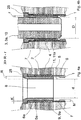
- Fig. 1a . 2a and 3a is an axial longitudinal section through a device according to the invention before the assembly of a valve element 3 is shown.
- the devices shown here for storing and dispensing liquid and / or gaseous media, in particular hydrogen, under pressure have a medium receiving medium container 1 made of a plastic material, in this case made of polyamide, a connected to the media container 1 valve connection element 2, preferably Aluminum and connectable to the valve connection element 2 valve element 3.
- the media container 1 has an integrally formed and projecting from the media container 1 outwardly collar 4 with a collar outer wall 5 and a collar inner wall 6. The end 7 of the collar 4 defines the free cross-section of an opening 8 of the media container.
- the valve connection element 2 is arranged in the region of this opening 8 and a partial region 5a of the collar outer wall 5 is arranged opposite a partial region 9a of a wall 9 of the valve connection element 2.
- the valve element 3 has a compression portion 10, which in the in the Fig. 1b . 2 B and 3b shown assembly state of the device is a partial region 6a of the collar inner wall 6 opposite. Between the portion 9a of the wall 9 and the compression portion 10, a return element 11, 11a is additionally arranged such that during assembly of the valve element 3, the collar 4 and the return element 11, 11a between the portion 9a of the wall 9 and the compression portion 10 is pressed together become.
- the return element 11, 11a is in this case made of a crosslinked plastic material, in particular of crosslinked polyethylene.
- the compression portion 10, the collar 4 and the return element 11, 11a are coordinated and designed so that an elastic deformation X of the return element 11, 11a is adjustable by the common compression of collar 4 and return element 11, 11a, which is larger as the maximum creep deformation Y of the collar 4 over the period of use of the device, so that the creep Y of the collar 4 over the return element 11, 11a is compensated and between the compression portion 10, the collar 4 and the return element 11, 11a and the portion 9a of Wall 9 a permanent interference fit arises.
- the interference fit allows sealing of the respective sealing areas against the pressurized medium.
- FIGS. 3a and 3b are correspondingly enlarged detailed representations in the FIGS. 1a . 2a .
- the elastic deformation X ie the difference between the wall thickness R of the restoring element and the wall thickness r of the restoring element, after the joint pressing collar 4 and return element 11, 11a, at least 0.3 times, preferably at least 0th , 5 times, more preferably at least 0.8 times, more preferably at least 1.0 times, preferably at least 1.2 times the wall thickness K of the collar 4 before assembly of the valve element 3, 3a corresponds.
- the wall thickness R of the restoring element 11, 11a is at least 1.8 times greater than the wall thickness K of the collar 4 enclosed by the partial region 5a of the collar outer wall 5 and the partial region 6a of the collar inner wall 6.
- the restoring element 11a and the collar 4 are each sleeve-shaped and nested, and the compression portion 10 of the return element 11a and the collar 4 enclosed.
- the restoring element to be put on the collar and not in the collar.
- the outer diameter D of the compression section 10 is prior to assembly of the valve element 3, 3a (see. Fig. 1a . 2a and 3b ) greater than the inner diameter d of the collar 4 and / or the return element 11a (see. Fig. 1a . 2a and 3a ).
- the restoring element 11, 11a has a defined surface irregularity, formed in particular by formations or recesses, on or in the surface of the restoring element 11, 11a.
- This defined surface irregularity is formed by a restoring element 11, 11a which is wavy in longitudinal section, the restoring element 11, 11a in this case having a constant wall thickness R.
- a plurality of locking elements 20 are arranged, which cooperate with a formed on the inner wall 9 of the valve connecting element 2 locking counter-element 21 (here in the form of a circumferential groove) such that during assembly of the valve element 3, 3a, a displacement of the return element 11, 11a is hindered relative to the valve connection element 2 and / or the collar 4.
- At least one latching element 20 has the advantage that during the assembly of the valve element 3, 3a the return element 11, 11a is quasi independently secured against displacement in the direction of the media container 1, by the or the latching elements 20 no longer from or Rast Gegenianan 21 can disengage, since they are prevented by the compression portion 10 on the return springs or are.
- Another advantage of at least one latching element 20 is that the return element 11, 11a can already be plugged onto or into the collar 4 before the valve connection element 2 is connected to the media container 1 (eg by means of a screw connection and / or by means of an adhesive layer).
- the latching element 20 is preferably formed integrally with the return element 11, 11a, for example mechanically formed from this (eg by milling) or already in the manufacture or molded (eg in the production of the return element 11, 11a in the plastic injection molding process).
- the wall thickness K of the collar 4 is less than the wall thickness M of the adjacent media container 1.
- the reset element 11, 11a is also elongated during the pressing, so that a clearance F between the unpressed reset element 11, 11a and the transition of the smaller wall thickness K of the collar 4 is provided to the wall thickness M of the adjacent media container.
- a sealing element 15 in the form of an O-ring is provided, which additionally seals the valve connecting element 2 against the valve element 3.
- no separate sealing element is provided in and between the region of the Verpressungsabitess 10 and the portion 9a of the wall 9, however, no separate sealing element is provided. This is not required due to the inventive construction of the device.
- the partial area 9a of the wall 9 has at least one defined surface irregularity in the form of a wave-shaped structure.
- the media container 1 is surrounded by a, preferably wound or braided, reinforcing layer 17 of carbon fibers in a thermoset matrix.
- valve element 3 can also be constructed in several parts, wherein the compression section 10 is arranged on a separate, in this case sleeve-shaped, first segment 3a of the valve element 3.
- 11a Above the collar 4 and / or the return element 11, 11a is also a sealing element 15th provided in the form of an O-ring which additionally seals the valve connection element 2 against the valve element 3.
- no separate sealing element In and between the region of the Verpressungsabterrorisms 10 and the portion 9a of the wall 9, however, no separate sealing element is provided. This is not required due to the inventive construction of the device.
- the above-mentioned sealing member 15 is disposed on a separate second segment 3b of the valve member 3 and can be easily replaced.
- Both the first segment 3a and the second segment 3b of the valve element 3 can be connected to the valve connection element 2 by means of a screw connection 16a, 16b.
- a first screw connection 16a between the first segment 3a and the valve connection element 2 and a second screw connection 16b between the second segment 3b of the valve element 3 and the valve connection element 2 are provided above the collar 4.
- the first segment 3a of the valve element 3 has a key receptacle for an Allen key, by means of which the first segment 3a can be connected to the valve connection element 2 via the first screw 16a.
- the second segment 3b of the valve connection element 3 has an extension of the media-carrying valve passage, via which the medium via the valve connection element 3 and 3b and can be supplied.
- the extension is designed such that it penetrates or passes through a continuous recess of the first segment 3a of the valve connection element 3 and protrudes so far into the media container 1 in the mounted state of the device that thermal loading of the device, in particular when refueling the medium container 1, is reduced.
- the extension projects beyond the first segment 3 a into the media container 1.
- the lower end of the extension projecting into the media container is at least a distance greater or equal to the outer diameter D of the compression section 10 of the first segment 3a of the valve connection element 3 from the first segment 3a.
- FIGS. 4a and 4b is a further detail of a device according to the invention can be seen.
- the return element 11a and the collar 4 are in this case also sleeve-shaped and inserted into each other and the compression portion 10 of the return element 11a and the collar 4 enclosed.
- the outer diameter D (see. Fig. 4b ) of the compression section 10 before mounting the valve element 3, 3a is greater than the inner diameter d (see. Fig. 4a ) of the collar 4 and / or the return element 11a prior to assembly of the valve element 3, 3a.
- the return element 11, 11a is formed from a crosslinked plastic material.
- the compression section 10, the collar 4 and the return element 11, 11a are coordinated and designed so that by the joint compression of collar 4 and return element 11, 11a an elastic deformation X (corresponds to the difference of the wall thickness R compared to the wall thickness r of the return element after assembly of the valve connecting element 2) is adjustable, which is greater than the maximum creep Y of the collar 4 over the period of use of the device, so that the creep Y of the collar 4 over the return element 11, 11 a compensated and between the compression section 10th , the collar 4, the return element 11, 11a and the portion 9a of the wall 9, a permanent interference fit is formed, which seals against the pressurized medium.
- the elastic deformation X here corresponds to at least 0.3 times, preferably at least 0.5 times, more preferably at least 0.8 times, more preferably at least 1.0 times, particularly preferably at least 1.2 times the wall thickness K of the collar 4 before mounting the valve element 3, 3a, 3b.
- the sleeve-shaped restoring element 11, 11a has, at its, the media container 1 facing away from a laterally projecting collar 25 which is arranged in sections or circumferentially on the return element 11, 11a, in particular integrally formed, is.
- the collar 25 interacts with a stepped undercut within the wall 9 of the valve connection element 2 and prevents so that during assembly of the valve element 3, 3a, the return element 11, 11a and / or the collar 4 is pushed in the direction of the media container 1 or in the media container 1 is pressed.
- the return element 11, 11a is inserted into the collar 4 after connecting the media container 1 to the valve connection element 2.
- Fig. 5a and 5b shows a detailed representation of a further embodiment of a device according to the invention, wherein the return element 11b is disc-shaped and, wherein at the upper end 7 of the collar 4, an opening 8 framing, with the collar 4 an angle ⁇ in the range of 80 ° -100 ° enclosing , Flange 30 is formed, wherein the flange bottom 31, the portion 5a of the collar outer wall 5 and the flange top 32 forms the portion 6a of the collar inner wall 6.
- the elastic deformation X here corresponds in each case to at least 0.3 times, preferably at least 0.5 times, more preferably at least 0.8 times, more preferably at least 1.0 times, particularly preferably at least 1.2 times Wall thickness K of the collar 4 before assembly of the valve element 3, 3a.
- valve connection element 2 can be configured in two or more parts for this embodiment in such a way that the valve connection element 2 can be mounted around the collar 4 or the flange 30.
- the flange 30 can also be formed only after the connection of the valve connection element 2 and the media container 1 (for example, by a forming tool from a region of the collar 4).
- the apparatus for storing and dispensing liquid and / or gaseous media under pressure comprises the steps of providing a media container 1 manufactured by a molding process, preferably a blow molding process, disposing the valve connecting member 2 to the media container 1, mounting the valve element 3, 3a wherein the collar 4 and the return element 11, 11a, 11b are pressed together between the portion 9a of the wall 9 and the compression portion 10, continuing the assembly of the valve member 3, 3a, until the common compression of collar 4 and return element 11, 11a , 11b has resulted in a deformation X of the return element 11, 11a, 11b which is greater than the maximum creep deformation Y of the collar 4 over the period of use of the device, so that the creep deformation Y of the collar 4 is compensated via the restoring element 11, 11a, 11b is and between the compression section 10, the Collar 4, the return element 11, 11 a, 11 b and the portion 9 a of the wall 9, a permanent interference fit arises.
- the press fit allows a seal of the respective sealing areas against the pressurized medium.
- the elastic deformation X here corresponds to at least 0.3 times, preferably at least 0.5 times, more preferably at least 0.8 times, more preferably at least 1.0 times, particularly preferably at least 1.2 times the wall thickness K of the collar 4 before mounting the valve element 3, 3a.
- FIGS. 6a to 6c is a schematic representation of the advantages of the device according to the invention can be seen.
- Fig. 6a Here, the state of the device prior to assembly or before connecting the valve element 3, 3a with the valve connection element 2.
- a portion 5a of the collar outer wall 5 is a portion 9a of a wall 9 of the valve connection element 2 arranged opposite, wherein the valve element 3, 3a a Compression section 10 which in the assembled state of the device (see. Fig. 6b and 6c )
- a portion 6a of the collar inner wall 6 is opposite.
- a return element 11, 11a, 11b is additionally arranged such that during assembly of the valve element 3, 3a, the collar 4 and the return element 11, 11a, 11b between the portion 9a of the wall 9 and the compression section 10 are pressed together (see. Fig. 6b and 6c ).
- the return element 11, 11a, 11b is formed from a cross-linked plastic material, preferably made of cross-linked polyethylene.
- the compression portion 10, the collar 4 and the return element 11, 11a, 11b are coordinated and designed so that an elastic deformation X of the return element 11, 11a, 11b is adjustable by the common pressing of collar 4 and restoring element 11, 11a, 11b which is greater than the maximum creep deformation Y of the collar 4 over the period of use of the device.
- the elastic deformation X here corresponds to at least 0.3 times, preferably at least 0.5 times, more preferably at least 0.8 times, more preferably at least 1.0 times, particularly preferably at least 1.2 times the wall thickness K of the collar 4 before mounting the valve element 3, 3a.
- the creep deformation Y to be compensated thereby results from the difference between the wall thickness k1 and the wall thickness k2 when the maximum creep deformation is reached or at an intermediate stage between the initial deformation in the state of purely elastic deformation of the collar 4 (corresponding to wall thickness k1) and the wall thickness k2 during the creep deformation or at the maximum creep deformation Y.
- the creep deformation Y of the collar 4 can be compensated via the return element 11, 11a, 11b, so that between the compression section 10, the collar 4, the restoring element 11, 11a, 11b and the portion 9a of Wall 9 a permanent press fit arises.
- the interference fit allows sealing of the respective sealing areas against the pressurized medium.
- the wall thickness R of the restoring element 11, 11a, 11b is in this case at least 1.8 times greater than the wall thickness K of the collar 4 before assembly of the valve element 3, 3a.
- the spring-back or the compensation of the creep deformation Y of the collar 4 via the elastic spring-back of the restoring element 11, 11a, 11b is shown in FIG Fig. 6c indicated schematically by the dashed arrows.
- the Fig. 7 shows a fuel energy conversion device according to the invention with a fuel cell unit 40, a media connection line 41, a pressure reducer 42 and a device according to the invention 43.
- the media connection line 41 connects the device 43 media sliding with the fuel cell unit 40.
- the stored in the device 43 according to the invention medium here hydrogen, flow to the fuel cell 40.
- a pressure reducer 42 is arranged in the direction of media flow in front of the fuel cell unit 40.
- the electrical energy converted in the fuel cell 40 from the fuel is supplied via electrical connecting lines 44 to an electrical load 50 (eg an electric motor) or an energy store 50 (eg a traction battery).
- the Fig. 8 shows the in the FIGS. 1a to 3b shown restoring elements 11, 11a, which have a plurality of locking elements 20 which cooperate with a corresponding formed on the inner wall 9 of the valve connection element 2 locking counter-element 21 such that during assembly of the valve element 3, 3a, a displacement of the return element 11, 11a relative to the Valve connection element 2 and / or the collar 4 is obstructed.
- the locking elements 20 are in this case formed integrally with the return element 11, 11a.
Landscapes
- Engineering & Computer Science (AREA)
- Mechanical Engineering (AREA)
- General Engineering & Computer Science (AREA)
- Sustainable Development (AREA)
- Sustainable Energy (AREA)
- Chemical & Material Sciences (AREA)
- Chemical Kinetics & Catalysis (AREA)
- Electrochemistry (AREA)
- General Chemical & Material Sciences (AREA)
- Life Sciences & Earth Sciences (AREA)
- Manufacturing & Machinery (AREA)
- Filling Or Discharging Of Gas Storage Vessels (AREA)
- Fuel Cell (AREA)
- Valve Housings (AREA)
- Cooling, Air Intake And Gas Exhaust, And Fuel Tank Arrangements In Propulsion Units (AREA)
Claims (19)
- Dispositif de stockage et de distribution de fluides liquides et/ou gazeux sous pression, présentant :- un réservoir de fluide (1) réceptionnant le fluide, constitué d'une matière plastique, de préférence constitué de polyamide,- au moins un élément de raccordement de vanne (2) relié au réservoir de fluide (1),- au moins un élément de vanne (3, 3a, 3b) pouvant être relié à l'élément de raccordement de vanne (2),le réservoir de fluide (1) présentant un col (4) formé d'une seule pièce et faisant saillie du réservoir de fluide (1), muni d'une paroi extérieure (5) de col et d'une paroi intérieure (6) de col,
l'extrémité (7) du col (4) définissant la section libre d'une ouverture (8) du réservoir de fluide (1),
l'élément de raccordement de vanne (2) étant disposé au niveau de cette ouverture (8), et une zone partielle (5a) de la paroi extérieure (5) de col étant disposée à l'opposé d'une paroi (9) de l'élément de raccordement de vanne (2), et
l'élément de vanne (3, 3a) présentant une section de pression (10) qui, à l'état de montage du dispositif, est située à l'opposé d'une zone partielle (6a) de la paroi intérieure (6) de col,
au moins un élément de rappel (11, 11a, 11b) étant en plus disposé entre la zone partielle (9a) et la section de pression (10) de manière à ce que lors du montage de
l'élément de vanne (3, 3a), le col (4) et l'élément de rappel (11, 11a, 11b) soient pressés en commun entre la zone partielle (9a) de la paroi (9) et la section de pression (10),
l'élément de rappel (11, 11a, 11b) étant réalisé à partir d'une matière plastique réticulée, de préférence en polyéthylène réticulé, et
la section de pression (10), le col (4) et l'élément de rappel (11, 11a, 11b) étant adaptés les uns aux autres et réalisés de manière à ce qu'en raison de la pression commune du col (4) et de l'élément de rappel (11, 11a, 11b) une déformation élastique (X) de l'élément de rappel (11, 11a, 11b) soit réglable, laquelle est supérieure à la déformation de fluage maximale (Y) du col (4) pendant la durée d'utilisation du dispositif,
de sorte que la déformation de fluage (Y) du col (4) est compensable par l'intermédiaire de l'élément de rappel (11, 11a, 11b) et qu'un siège de pression durable est obtenu entre la section de pression (10), le col (4), l'élément de rappel (11, 11a, 11b) et la zone partielle (9a) de la paroi (9),
caractérisé en ce que
l'élément de rappel (11a) et le col (4) sont réalisés en forme de douille et sont emboîtés l'un dans l'autre ou enfoncés l'un sur l'autre, et en ce que la section de pression (10) est entourée par l'élément de rappel (11a) et le col (4), le diamètre extérieur (D) de la section de pression (10), avant le montage de l'élément de vanne (3, 3a), étant supérieur au diamètre intérieur (d) du col (4) et/ou de l'élément de rappel (11a). - Dispositif selon la revendication 1, caractérisé en ce que la déformation élastique (X) correspond au moins à 0,3 fois, de préférence au moins à 0,8 fois l'épaisseur de paroi (K) du col (4).
- Dispositif selon la revendication 1 ou 2, caractérisé en ce que l'épaisseur de paroi (R) de l'élément de rappel (11, 11a, 11b) est au moins 1,5 fois supérieure à l'épaisseur de paroi (K) du col (4).
- Dispositif selon l'une quelconque des revendications précédentes, caractérisé en ce que l'élément de rappel (11, 11a, 11b) présente au moins une régularité de surface définie, formée par déformations ou évidements sur ou dans la surface de l'élément de rappel (11, 11a, 11b).
- Dispositif selon la revendication 4, caractérisé en ce que la régularité de surface définie est formée par un élément de rappel (11, 11a, 11b) ondulé en section longitudinale et/ou transversale.
- Dispositif selon la revendication 5, caractérisé en ce que l'élément de rappel (11, 11a, 11b) présente une épaisseur de paroi (R) constante.
- Dispositif selon l'une quelconque des revendications précédentes, caractérisé en ce qu'au moins un élément d'encliquetage (20) est disposé sur l'élément de rappel (11, 11a), lequel élément d'encliquetage coopère avec un contre-élément d'encliquetage (21) réalisé sur la paroi intérieure (9) de l'élément de raccordement de vanne (2) de manière à ce que lors du montage de l'élément de vanne (3, 3a), un déplacement de l'élément de rappel (11, 11a) par rapport à l'élément de raccordement de vanne (2) et/ou au col (4) soit empêché.
- Dispositif selon l'une quelconque des revendications précédentes, caractérisé en ce que l'épaisseur de paroi (K) du col (4) est inférieure à l'épaisseur de paroi (M) du réservoir de fluide (1) adjacent.
- Dispositif selon l'une quelconque des revendications précédentes, caractérisé en ce que l'élément de vanne (3) est construit en plusieurs parties, la section de pression (10) étant disposée sur un premier segment (3a) séparé de l'élément de vanne (3).
- Dispositif selon la revendication 9, caractérisé en ce que le premier segment (3a) est en forme de douille.
- Dispositif selon l'une quelconque des revendications précédentes, caractérisé en ce qu'un élément d'étanchéité (15), de préférence un joint torique (15), est ménagé au-dessus du col (4) et/ou de l'élément de rappel (11, 11a, 11b), lequel élément d'étanchéité obture l'élément de raccordement de vanne (2) contre l'élément de vanne (3).
- Dispositif selon les revendications 9 et 11 ou 10 et 11, caractérisé en ce que l'élément d'étanchéité (15) est disposé sur un second segment (3b) séparé de l'élément de vanne (3).
- Dispositif selon l'une quelconque des revendications précédentes, caractérisé en ce qu'aucun élément d'étanchéité séparé n'est ménagé dans et entre la partie de la section de pression (10) et la zone partielle (9a) de la paroi (9).
- Dispositif selon l'une quelconque des revendications précédentes, caractérisé en ce qu'au-dessus du col (4) est ménagé un raccord vissé (16, 16a, 16b) entre l'élément de vanne (3, 3a, 3b) et l'élément de raccordement de vanne (2).
- Dispositif selon l'une quelconque des revendications précédentes, caractérisé en ce que la zone partielle (9a) de la paroi (9) présente au moins une régularité de surface définie.
- Dispositif selon l'une quelconque des revendications précédentes, caractérisé en ce que le réservoir de fluide (1) est entouré par une couche de renforcement (17) de préférence enroulée ou tressée.
- Dispositif de transformation de combustible en énergie, comprenant- une unité de piles à combustible (40)- au moins une conduite de raccordement de fluide (41)- au moins un réducteur de pression (42) et- au moins un dispositif (43) selon l'une quelconque des revendications précédentes 1 à 16,la conduite de raccordement de fluide (41) reliant le dispositif (43) à l'unité de piles à combustible (4) en guidant le fluide, et le réducteur de pression (42), en direction du flux du fluide, étant disposé en amont de l'unité de piles à combustible (40).
- Véhicule automobile comprenant un dispositif selon l'une quelconque des revendications précédentes 1 à 16 ou comprenant un dispositif de transformation de combustible en énergie selon la revendication 17.
- Procédé de montage d'un dispositif de stockage et de distribution de fluides liquides et/ou gazeux sous pression selon l'une quelconque des revendications 1 à 16, comprenant les étapes suivantes :- fourniture d'un réservoir de fluide (1) fabriqué selon un procédé de façonnage, de préférence un procédé de moulage par soufflage,- agencement de l'élément de raccordement de vanne (2) sur le réservoir de fluide (1),- montage de l'élément de vanne (3, 3a), le col (4) et l'élément de rappel (11, 11a, 11b) étant pressés en commun entre la zone partielle (9a) de la paroi (9) et la section de pression (10),- poursuite du montage de l'élément de vanne (3, 3a, 3b) jusqu'à ce que la pression commune du col (4) et de l'élément de rappel (11, 11a, 11b) ait conduit à une déformation (X) de l'élément de rappel (11, 11a, 11b) qui soit supérieure à la déformation de fluage (Y) maximale du col (4) pendant la durée d'utilisation du dispositif,de sorte que la déformation de fluage (Y) du col (4) est compensée par l'intermédiaire de l'élément de rappel (11, 11a, 11b) et qu'un siège de pression durable est obtenu entre la section de pression (10), le col (4), l'élément de rappel (11, 11a, 11b) et la zone partielle (9a) de la paroi (9),
caractérisé en ce que
l'élément de rappel (11a) et le col (4) sont réalisés en forme de douille et sont emboîtés l'un dans l'autre ou enfoncés l'un sur l'autre, et en ce que la section de pression (10) est entourée par l'élément de rappel (11a) et le col (4), le diamètre extérieur (D) de la section de pression (10), avant le montage de l'élément de vanne (3, 3a), étant supérieur au diamètre intérieur (d) du col (4) et/ou de l'élément de rappel (11a).
Applications Claiming Priority (3)
| Application Number | Priority Date | Filing Date | Title |
|---|---|---|---|
| DE202013100594 | 2013-02-08 | ||
| DE102013101425.9A DE102013101425A1 (de) | 2013-02-08 | 2013-02-13 | Vorrichtung zur Speicherung und Abgabe von flüssigen und / oder gasförmigen Medien unter Druck sowie Kraftstoffenergieumwandlungsvorrichtung und Verfahren zur Montage einer Vorrichtung zur Speicherung und Abgabe von flüssigen und/oder gasförmigen Medien unter Druck |
| PCT/EP2014/000324 WO2014121935A2 (fr) | 2013-02-08 | 2014-02-06 | Dispositif de stockage et de distribution de fluides liquides et/ou gazeux sous pression et dispositif de conversion de l'énergie d'un carburant, et procédé de montage d'un dispositif de stockage et de distribution de fluides liquides et/ou gazeux sous pression |
Publications (2)
| Publication Number | Publication Date |
|---|---|
| EP2954249A2 EP2954249A2 (fr) | 2015-12-16 |
| EP2954249B1 true EP2954249B1 (fr) | 2018-05-23 |
Family
ID=50071581
Family Applications (1)
| Application Number | Title | Priority Date | Filing Date |
|---|---|---|---|
| EP14703538.0A Not-in-force EP2954249B1 (fr) | 2013-02-08 | 2014-02-06 | Dispositif de stockage et de distribution de fluides liquides et/ou gazeux sous pression et dispositif de conversion de l'énergie d'un carburant, et procédé de montage d'un dispositif de stockage et de distribution de fluides liquides et/ou gazeux sous pression |
Country Status (6)
| Country | Link |
|---|---|
| US (1) | US9816668B2 (fr) |
| EP (1) | EP2954249B1 (fr) |
| JP (1) | JP6279616B2 (fr) |
| CN (1) | CN105121933B (fr) |
| DE (1) | DE102013101425A1 (fr) |
| WO (1) | WO2014121935A2 (fr) |
Cited By (1)
| Publication number | Priority date | Publication date | Assignee | Title |
|---|---|---|---|---|
| EP4603740A3 (fr) * | 2019-09-23 | 2025-11-26 | Noble Gas Systems, Inc. | Retenue d'embout de récipient sous pression |
Families Citing this family (12)
| Publication number | Priority date | Publication date | Assignee | Title |
|---|---|---|---|---|
| DE102014000621B4 (de) | 2014-01-18 | 2022-08-11 | Cellcentric Gmbh & Co. Kg | Druckgasbehälter |
| EP3012507B1 (fr) * | 2014-10-23 | 2019-02-06 | Magna Steyr Fuel Systems GesmbH | Procédé et outil destinés à la fabrication d'un récipient sous pression et récipient sous pression |
| US9677713B1 (en) * | 2015-11-24 | 2017-06-13 | Lawrence Livermore National Security, Llc | Compact insert design for cryogenic pressure vessels |
| PL242453B1 (pl) | 2017-03-03 | 2023-02-27 | Worthington Ind Inc | Butla przystosowana do magazynowania gazu oraz złączka do takiej butli |
| JP7479622B2 (ja) * | 2017-10-27 | 2024-05-09 | 日本製鋼所M&E株式会社 | 蓄圧容器 |
| DE102019210514A1 (de) * | 2019-07-17 | 2021-01-21 | Robert Bosch Gmbh | Tankvorrichtung zur Speicherung eines gasförmigen Mediums und Verfahren zur Herstellung einer Tankvorrichtung |
| ES2944713T3 (es) * | 2019-08-30 | 2023-06-23 | Nproxx B V | Recipiente a presión |
| ES2956520T3 (es) | 2021-03-31 | 2023-12-22 | Isi Gmbh | Válvula para cerrar un recipiente de gas |
| JP2023142362A (ja) * | 2022-03-25 | 2023-10-05 | サムテック株式会社 | 容器及び容器の製造方法 |
| CN115823476B (zh) * | 2022-11-23 | 2024-12-24 | 浙江工业大学 | 一种iv型储氢瓶双向贯穿式金属瓶口结构 |
| KR20240094869A (ko) * | 2022-12-16 | 2024-06-25 | 현대자동차주식회사 | 압력용기 및 압력용기의 제조방법 |
| DE102024123807A1 (de) * | 2024-08-20 | 2026-02-26 | Bayerische Motoren Werke Aktiengesellschaft | Druckbehälter zum Speichern von Brennstoff, Energiewandlersystem, Fahrzeug und Verfahren zum Herstellen eines Druckbehälters |
Family Cites Families (17)
| Publication number | Priority date | Publication date | Assignee | Title |
|---|---|---|---|---|
| DE2152123C3 (de) * | 1971-10-20 | 1974-07-11 | Elektrische Licht- Und Kraftanlagen Ag, 3579 Frielendorf | Druckbehälter |
| JPS55718Y2 (fr) * | 1976-12-02 | 1980-01-10 | ||
| DE19631546C1 (de) | 1996-07-24 | 1997-11-13 | Mannesmann Ag | Composite-Druckbehälter zur Speicherung von gasförmigen Medien unter Druck mit einem Liner aus Kunststoff |
| DE19630328C2 (de) | 1996-07-26 | 1999-11-18 | Maurer Friedrich Soehne | Überbrückungsvorrichtung für Fugenspalte |
| JP2001050494A (ja) * | 1999-08-11 | 2001-02-23 | High Pressure Gas Safety Institute Of Japan | 耐圧容器 |
| JP2001214998A (ja) * | 2000-02-03 | 2001-08-10 | Mitsubishi Chemicals Corp | 耐圧容器 |
| US7731051B2 (en) | 2005-07-13 | 2010-06-08 | Gm Global Technology Operations, Inc. | Hydrogen pressure tank including an inner liner with an outer annular flange |
| DE102007011211B3 (de) | 2007-03-08 | 2008-08-14 | Xperion Gmbh | Druckbehälter zur Speicherung von flüssigen oder gasförmigen Medien |
| DE102009025386A1 (de) * | 2009-06-16 | 2010-12-23 | Rehau Ag + Co. | Speicher zur Aufnahme eines Fluids |
| DE102009049948B4 (de) * | 2009-10-19 | 2012-02-02 | Kautex Maschinenbau Gmbh | Druckbehälter |
| JP5179458B2 (ja) * | 2009-11-11 | 2013-04-10 | 八千代工業株式会社 | 圧力容器のシール構造 |
| EP2539625A1 (fr) * | 2010-02-26 | 2013-01-02 | Dynetek Industries Ltd | Système d'étanchéité pour la sortie d'une bouteille de gaz comprimé revêtue intérieurement de plastique |
| US8397938B2 (en) * | 2010-03-10 | 2013-03-19 | GM Global Technology Operations LLC | Clamped liner-boss connection |
| DE102010018700B4 (de) * | 2010-04-29 | 2019-05-09 | Magna Steyr Fahrzeugtechnik Ag & Co. Kg | Druckbehälter |
| DE102010023386A1 (de) * | 2010-06-10 | 2011-12-15 | Volkswagen Ag | Druckbehälter |
| EP2742272B1 (fr) * | 2011-08-08 | 2016-04-20 | Rehau AG & Co | Dispositif pour l'accumulation et la distribution de milieux liquides et/ou gazeux sous pression, ainsi que dispositif de transformation d'énergie de carburant et procédé pour le montage d'un dispositif pour l'accumulation et la distribution de milieux liquides et/ou gazeux sous pression |
| DE102011052490A1 (de) * | 2011-08-08 | 2013-02-14 | Rehau Ag + Co. | Vorrichtung zur Speicherung und Abgabe von flüssigen und/oder gasförmigen Medien unter Druck sowie Kraftstoffenergieumwandlungsvorrichtung und Verfahren zur Montage einer Vorrichtung zur Speicherung und Abgabe von flüssigen und/oder gasförmigen Medien unter Druck |
-
2013
- 2013-02-13 DE DE102013101425.9A patent/DE102013101425A1/de not_active Withdrawn
-
2014
- 2014-02-06 US US14/766,311 patent/US9816668B2/en active Active
- 2014-02-06 JP JP2015556422A patent/JP6279616B2/ja not_active Expired - Fee Related
- 2014-02-06 CN CN201480019150.5A patent/CN105121933B/zh not_active Expired - Fee Related
- 2014-02-06 EP EP14703538.0A patent/EP2954249B1/fr not_active Not-in-force
- 2014-02-06 WO PCT/EP2014/000324 patent/WO2014121935A2/fr not_active Ceased
Non-Patent Citations (1)
| Title |
|---|
| None * |
Cited By (1)
| Publication number | Priority date | Publication date | Assignee | Title |
|---|---|---|---|---|
| EP4603740A3 (fr) * | 2019-09-23 | 2025-11-26 | Noble Gas Systems, Inc. | Retenue d'embout de récipient sous pression |
Also Published As
| Publication number | Publication date |
|---|---|
| JP2016509175A (ja) | 2016-03-24 |
| CN105121933A (zh) | 2015-12-02 |
| DE102013101425A1 (de) | 2014-08-28 |
| US9816668B2 (en) | 2017-11-14 |
| WO2014121935A2 (fr) | 2014-08-14 |
| CN105121933B (zh) | 2018-03-20 |
| JP6279616B2 (ja) | 2018-02-14 |
| EP2954249A2 (fr) | 2015-12-16 |
| WO2014121935A3 (fr) | 2014-11-20 |
| US20150362130A1 (en) | 2015-12-17 |
Similar Documents
| Publication | Publication Date | Title |
|---|---|---|
| EP2954249B1 (fr) | Dispositif de stockage et de distribution de fluides liquides et/ou gazeux sous pression et dispositif de conversion de l'énergie d'un carburant, et procédé de montage d'un dispositif de stockage et de distribution de fluides liquides et/ou gazeux sous pression | |
| EP2742272B1 (fr) | Dispositif pour l'accumulation et la distribution de milieux liquides et/ou gazeux sous pression, ainsi que dispositif de transformation d'énergie de carburant et procédé pour le montage d'un dispositif pour l'accumulation et la distribution de milieux liquides et/ou gazeux sous pression | |
| DE102011052490A1 (de) | Vorrichtung zur Speicherung und Abgabe von flüssigen und/oder gasförmigen Medien unter Druck sowie Kraftstoffenergieumwandlungsvorrichtung und Verfahren zur Montage einer Vorrichtung zur Speicherung und Abgabe von flüssigen und/oder gasförmigen Medien unter Druck | |
| DE3317061C2 (de) | Flanschverbindungsanordnung | |
| EP4267882B1 (fr) | Réservoir sous pression pour véhicule fonctionnant au gaz | |
| EP3786511B1 (fr) | Récipient sous pression | |
| DE102010023386A1 (de) | Druckbehälter | |
| DE102018118383A1 (de) | Hochdruckbehälter | |
| EP2895317A1 (fr) | Rouleau presseur destiné à déposer un demi-produit en forme de bande | |
| DE19641751A1 (de) | Zweikomponenten-Anbindungselement | |
| WO2007079971A1 (fr) | Contenant sous pression destiné à stocker des fluides liquides ou gazeux | |
| DE202012101004U1 (de) | Vorrichtung zur Speicherung und Abgabe von flüssigen und/oder gasförmigen Medien unter Druck sowie Kraftstoffenergieumwandlungsvorrichtung | |
| DE19651817C2 (de) | Rohrpreßkupplung | |
| EP2831419B1 (fr) | Système d'étanchéité | |
| EP1965105B1 (fr) | Agencement d'étanchéification | |
| DE102010008263B4 (de) | Druckbehälter und Verfahren zur Herstellung eines Druckbehälters | |
| DE102013107061A1 (de) | Aerosolbehälter | |
| DE19510714C1 (de) | Übergangsstück für Rohrleitungen | |
| DE2921669A1 (de) | Dichtung | |
| EP2213500B1 (fr) | Conduite de carburant et procédé de fabrication d'une conduite de carburant | |
| EP4077999B1 (fr) | Raccord enfichable et ensemble raccord enfichable | |
| WO2013091833A2 (fr) | Dispositif de stockage et de distribution de milieux liquides et/ou gazeux sous pression et dispositif de conversion de l'énergie d'un combustible et procédé de fabrication d'un dispositif de stockage et de distribution de milieux liquides et/ou gazeux sous pression | |
| DE102012110729A1 (de) | Kunststoffrohr | |
| EP1985388A1 (fr) | Poutre métallique résistant aux hautes pressions et son procédé de fabrication | |
| DE102024123051A1 (de) | Drucktank für gasbetriebenes Fahrzeug |
Legal Events
| Date | Code | Title | Description |
|---|---|---|---|
| PUAI | Public reference made under article 153(3) epc to a published international application that has entered the european phase |
Free format text: ORIGINAL CODE: 0009012 |
|
| 17P | Request for examination filed |
Effective date: 20150729 |
|
| AK | Designated contracting states |
Kind code of ref document: A2 Designated state(s): AL AT BE BG CH CY CZ DE DK EE ES FI FR GB GR HR HU IE IS IT LI LT LU LV MC MK MT NL NO PL PT RO RS SE SI SK SM TR |
|
| AX | Request for extension of the european patent |
Extension state: BA ME |
|
| DAX | Request for extension of the european patent (deleted) | ||
| GRAP | Despatch of communication of intention to grant a patent |
Free format text: ORIGINAL CODE: EPIDOSNIGR1 |
|
| STAA | Information on the status of an ep patent application or granted ep patent |
Free format text: STATUS: GRANT OF PATENT IS INTENDED |
|
| INTG | Intention to grant announced |
Effective date: 20171025 |
|
| GRAS | Grant fee paid |
Free format text: ORIGINAL CODE: EPIDOSNIGR3 |
|
| GRAA | (expected) grant |
Free format text: ORIGINAL CODE: 0009210 |
|
| STAA | Information on the status of an ep patent application or granted ep patent |
Free format text: STATUS: THE PATENT HAS BEEN GRANTED |
|
| AK | Designated contracting states |
Kind code of ref document: B1 Designated state(s): AL AT BE BG CH CY CZ DE DK EE ES FI FR GB GR HR HU IE IS IT LI LT LU LV MC MK MT NL NO PL PT RO RS SE SI SK SM TR |
|
| REG | Reference to a national code |
Ref country code: GB Ref legal event code: FG4D Free format text: NOT ENGLISH |
|
| REG | Reference to a national code |
Ref country code: CH Ref legal event code: EP |
|
| REG | Reference to a national code |
Ref country code: IE Ref legal event code: FG4D Free format text: LANGUAGE OF EP DOCUMENT: GERMAN |
|
| REG | Reference to a national code |
Ref country code: AT Ref legal event code: REF Ref document number: 1001801 Country of ref document: AT Kind code of ref document: T Effective date: 20180615 |
|
| REG | Reference to a national code |
Ref country code: DE Ref legal event code: R096 Ref document number: 502014008332 Country of ref document: DE |
|
| REG | Reference to a national code |
Ref country code: NL Ref legal event code: MP Effective date: 20180523 |
|
| REG | Reference to a national code |
Ref country code: LT Ref legal event code: MG4D |
|
| PG25 | Lapsed in a contracting state [announced via postgrant information from national office to epo] |
Ref country code: BG Free format text: LAPSE BECAUSE OF FAILURE TO SUBMIT A TRANSLATION OF THE DESCRIPTION OR TO PAY THE FEE WITHIN THE PRESCRIBED TIME-LIMIT Effective date: 20180823 Ref country code: FI Free format text: LAPSE BECAUSE OF FAILURE TO SUBMIT A TRANSLATION OF THE DESCRIPTION OR TO PAY THE FEE WITHIN THE PRESCRIBED TIME-LIMIT Effective date: 20180523 Ref country code: NO Free format text: LAPSE BECAUSE OF FAILURE TO SUBMIT A TRANSLATION OF THE DESCRIPTION OR TO PAY THE FEE WITHIN THE PRESCRIBED TIME-LIMIT Effective date: 20180823 Ref country code: SE Free format text: LAPSE BECAUSE OF FAILURE TO SUBMIT A TRANSLATION OF THE DESCRIPTION OR TO PAY THE FEE WITHIN THE PRESCRIBED TIME-LIMIT Effective date: 20180523 Ref country code: LT Free format text: LAPSE BECAUSE OF FAILURE TO SUBMIT A TRANSLATION OF THE DESCRIPTION OR TO PAY THE FEE WITHIN THE PRESCRIBED TIME-LIMIT Effective date: 20180523 Ref country code: ES Free format text: LAPSE BECAUSE OF FAILURE TO SUBMIT A TRANSLATION OF THE DESCRIPTION OR TO PAY THE FEE WITHIN THE PRESCRIBED TIME-LIMIT Effective date: 20180523 |
|
| PG25 | Lapsed in a contracting state [announced via postgrant information from national office to epo] |
Ref country code: RS Free format text: LAPSE BECAUSE OF FAILURE TO SUBMIT A TRANSLATION OF THE DESCRIPTION OR TO PAY THE FEE WITHIN THE PRESCRIBED TIME-LIMIT Effective date: 20180523 Ref country code: NL Free format text: LAPSE BECAUSE OF FAILURE TO SUBMIT A TRANSLATION OF THE DESCRIPTION OR TO PAY THE FEE WITHIN THE PRESCRIBED TIME-LIMIT Effective date: 20180523 Ref country code: HR Free format text: LAPSE BECAUSE OF FAILURE TO SUBMIT A TRANSLATION OF THE DESCRIPTION OR TO PAY THE FEE WITHIN THE PRESCRIBED TIME-LIMIT Effective date: 20180523 Ref country code: GR Free format text: LAPSE BECAUSE OF FAILURE TO SUBMIT A TRANSLATION OF THE DESCRIPTION OR TO PAY THE FEE WITHIN THE PRESCRIBED TIME-LIMIT Effective date: 20180824 Ref country code: LV Free format text: LAPSE BECAUSE OF FAILURE TO SUBMIT A TRANSLATION OF THE DESCRIPTION OR TO PAY THE FEE WITHIN THE PRESCRIBED TIME-LIMIT Effective date: 20180523 |
|
| PG25 | Lapsed in a contracting state [announced via postgrant information from national office to epo] |
Ref country code: RO Free format text: LAPSE BECAUSE OF FAILURE TO SUBMIT A TRANSLATION OF THE DESCRIPTION OR TO PAY THE FEE WITHIN THE PRESCRIBED TIME-LIMIT Effective date: 20180523 Ref country code: SK Free format text: LAPSE BECAUSE OF FAILURE TO SUBMIT A TRANSLATION OF THE DESCRIPTION OR TO PAY THE FEE WITHIN THE PRESCRIBED TIME-LIMIT Effective date: 20180523 Ref country code: DK Free format text: LAPSE BECAUSE OF FAILURE TO SUBMIT A TRANSLATION OF THE DESCRIPTION OR TO PAY THE FEE WITHIN THE PRESCRIBED TIME-LIMIT Effective date: 20180523 Ref country code: EE Free format text: LAPSE BECAUSE OF FAILURE TO SUBMIT A TRANSLATION OF THE DESCRIPTION OR TO PAY THE FEE WITHIN THE PRESCRIBED TIME-LIMIT Effective date: 20180523 Ref country code: CZ Free format text: LAPSE BECAUSE OF FAILURE TO SUBMIT A TRANSLATION OF THE DESCRIPTION OR TO PAY THE FEE WITHIN THE PRESCRIBED TIME-LIMIT Effective date: 20180523 Ref country code: PL Free format text: LAPSE BECAUSE OF FAILURE TO SUBMIT A TRANSLATION OF THE DESCRIPTION OR TO PAY THE FEE WITHIN THE PRESCRIBED TIME-LIMIT Effective date: 20180523 |
|
| REG | Reference to a national code |
Ref country code: DE Ref legal event code: R097 Ref document number: 502014008332 Country of ref document: DE |
|
| PG25 | Lapsed in a contracting state [announced via postgrant information from national office to epo] |
Ref country code: SM Free format text: LAPSE BECAUSE OF FAILURE TO SUBMIT A TRANSLATION OF THE DESCRIPTION OR TO PAY THE FEE WITHIN THE PRESCRIBED TIME-LIMIT Effective date: 20180523 Ref country code: IT Free format text: LAPSE BECAUSE OF FAILURE TO SUBMIT A TRANSLATION OF THE DESCRIPTION OR TO PAY THE FEE WITHIN THE PRESCRIBED TIME-LIMIT Effective date: 20180523 |
|
| PLBE | No opposition filed within time limit |
Free format text: ORIGINAL CODE: 0009261 |
|
| STAA | Information on the status of an ep patent application or granted ep patent |
Free format text: STATUS: NO OPPOSITION FILED WITHIN TIME LIMIT |
|
| PGFP | Annual fee paid to national office [announced via postgrant information from national office to epo] |
Ref country code: GB Payment date: 20190123 Year of fee payment: 7 |
|
| 26N | No opposition filed |
Effective date: 20190226 |
|
| PG25 | Lapsed in a contracting state [announced via postgrant information from national office to epo] |
Ref country code: SI Free format text: LAPSE BECAUSE OF FAILURE TO SUBMIT A TRANSLATION OF THE DESCRIPTION OR TO PAY THE FEE WITHIN THE PRESCRIBED TIME-LIMIT Effective date: 20180523 |
|
| PGFP | Annual fee paid to national office [announced via postgrant information from national office to epo] |
Ref country code: FR Payment date: 20190213 Year of fee payment: 6 Ref country code: AT Payment date: 20190211 Year of fee payment: 6 |
|
| REG | Reference to a national code |
Ref country code: CH Ref legal event code: PL |
|
| PG25 | Lapsed in a contracting state [announced via postgrant information from national office to epo] |
Ref country code: MC Free format text: LAPSE BECAUSE OF FAILURE TO SUBMIT A TRANSLATION OF THE DESCRIPTION OR TO PAY THE FEE WITHIN THE PRESCRIBED TIME-LIMIT Effective date: 20180523 Ref country code: LU Free format text: LAPSE BECAUSE OF NON-PAYMENT OF DUE FEES Effective date: 20190206 |
|
| REG | Reference to a national code |
Ref country code: BE Ref legal event code: MM Effective date: 20190228 |
|
| REG | Reference to a national code |
Ref country code: IE Ref legal event code: MM4A |
|
| PG25 | Lapsed in a contracting state [announced via postgrant information from national office to epo] |
Ref country code: AL Free format text: LAPSE BECAUSE OF FAILURE TO SUBMIT A TRANSLATION OF THE DESCRIPTION OR TO PAY THE FEE WITHIN THE PRESCRIBED TIME-LIMIT Effective date: 20180523 |
|
| PG25 | Lapsed in a contracting state [announced via postgrant information from national office to epo] |
Ref country code: LI Free format text: LAPSE BECAUSE OF NON-PAYMENT OF DUE FEES Effective date: 20190228 Ref country code: CH Free format text: LAPSE BECAUSE OF NON-PAYMENT OF DUE FEES Effective date: 20190228 |
|
| PG25 | Lapsed in a contracting state [announced via postgrant information from national office to epo] |
Ref country code: IE Free format text: LAPSE BECAUSE OF NON-PAYMENT OF DUE FEES Effective date: 20190206 |
|
| PG25 | Lapsed in a contracting state [announced via postgrant information from national office to epo] |
Ref country code: BE Free format text: LAPSE BECAUSE OF NON-PAYMENT OF DUE FEES Effective date: 20190228 |
|
| PG25 | Lapsed in a contracting state [announced via postgrant information from national office to epo] |
Ref country code: TR Free format text: LAPSE BECAUSE OF FAILURE TO SUBMIT A TRANSLATION OF THE DESCRIPTION OR TO PAY THE FEE WITHIN THE PRESCRIBED TIME-LIMIT Effective date: 20180523 |
|
| PG25 | Lapsed in a contracting state [announced via postgrant information from national office to epo] |
Ref country code: MT Free format text: LAPSE BECAUSE OF FAILURE TO SUBMIT A TRANSLATION OF THE DESCRIPTION OR TO PAY THE FEE WITHIN THE PRESCRIBED TIME-LIMIT Effective date: 20180523 Ref country code: PT Free format text: LAPSE BECAUSE OF FAILURE TO SUBMIT A TRANSLATION OF THE DESCRIPTION OR TO PAY THE FEE WITHIN THE PRESCRIBED TIME-LIMIT Effective date: 20180924 |
|
| REG | Reference to a national code |
Ref country code: AT Ref legal event code: MM01 Ref document number: 1001801 Country of ref document: AT Kind code of ref document: T Effective date: 20200206 |
|
| GBPC | Gb: european patent ceased through non-payment of renewal fee |
Effective date: 20200206 |
|
| PG25 | Lapsed in a contracting state [announced via postgrant information from national office to epo] |
Ref country code: AT Free format text: LAPSE BECAUSE OF NON-PAYMENT OF DUE FEES Effective date: 20200206 |
|
| PG25 | Lapsed in a contracting state [announced via postgrant information from national office to epo] |
Ref country code: GB Free format text: LAPSE BECAUSE OF NON-PAYMENT OF DUE FEES Effective date: 20200206 Ref country code: FR Free format text: LAPSE BECAUSE OF NON-PAYMENT OF DUE FEES Effective date: 20200229 |
|
| PG25 | Lapsed in a contracting state [announced via postgrant information from national office to epo] |
Ref country code: CY Free format text: LAPSE BECAUSE OF FAILURE TO SUBMIT A TRANSLATION OF THE DESCRIPTION OR TO PAY THE FEE WITHIN THE PRESCRIBED TIME-LIMIT Effective date: 20180523 |
|
| PG25 | Lapsed in a contracting state [announced via postgrant information from national office to epo] |
Ref country code: IS Free format text: LAPSE BECAUSE OF FAILURE TO SUBMIT A TRANSLATION OF THE DESCRIPTION OR TO PAY THE FEE WITHIN THE PRESCRIBED TIME-LIMIT Effective date: 20180923 |
|
| PG25 | Lapsed in a contracting state [announced via postgrant information from national office to epo] |
Ref country code: HU Free format text: LAPSE BECAUSE OF FAILURE TO SUBMIT A TRANSLATION OF THE DESCRIPTION OR TO PAY THE FEE WITHIN THE PRESCRIBED TIME-LIMIT; INVALID AB INITIO Effective date: 20140206 |
|
| REG | Reference to a national code |
Ref country code: DE Ref legal event code: R081 Ref document number: 502014008332 Country of ref document: DE Owner name: REHAU AUTOMOTIVE SE & CO. KG, DE Free format text: FORMER OWNER: REHAU AG + CO, 95111 REHAU, DE |
|
| PGFP | Annual fee paid to national office [announced via postgrant information from national office to epo] |
Ref country code: DE Payment date: 20220228 Year of fee payment: 9 |
|
| PG25 | Lapsed in a contracting state [announced via postgrant information from national office to epo] |
Ref country code: MK Free format text: LAPSE BECAUSE OF FAILURE TO SUBMIT A TRANSLATION OF THE DESCRIPTION OR TO PAY THE FEE WITHIN THE PRESCRIBED TIME-LIMIT Effective date: 20180523 |
|
| REG | Reference to a national code |
Ref country code: DE Ref legal event code: R119 Ref document number: 502014008332 Country of ref document: DE |
|
| PG25 | Lapsed in a contracting state [announced via postgrant information from national office to epo] |
Ref country code: DE Free format text: LAPSE BECAUSE OF NON-PAYMENT OF DUE FEES Effective date: 20230901 |