EP2954532B1 - Systèmes et méthodes de production d'électricité utilisant l'énergie stockée d'une alimentation en air ves - Google Patents
Systèmes et méthodes de production d'électricité utilisant l'énergie stockée d'une alimentation en air ves Download PDFInfo
- Publication number
- EP2954532B1 EP2954532B1 EP13874435.4A EP13874435A EP2954532B1 EP 2954532 B1 EP2954532 B1 EP 2954532B1 EP 13874435 A EP13874435 A EP 13874435A EP 2954532 B1 EP2954532 B1 EP 2954532B1
- Authority
- EP
- European Patent Office
- Prior art keywords
- compressed air
- air
- pressure
- control room
- main control
- Prior art date
- Legal status (The legal status is an assumption and is not a legal conclusion. Google has not performed a legal analysis and makes no representation as to the accuracy of the status listed.)
- Not-in-force
Links
- 238000000034 method Methods 0.000 title claims description 10
- 238000013461 design Methods 0.000 claims description 9
- XLYOFNOQVPJJNP-UHFFFAOYSA-N water Substances O XLYOFNOQVPJJNP-UHFFFAOYSA-N 0.000 description 10
- 238000010248 power generation Methods 0.000 description 8
- 230000010485 coping Effects 0.000 description 6
- 230000008859 change Effects 0.000 description 4
- 230000005611 electricity Effects 0.000 description 4
- 238000005381 potential energy Methods 0.000 description 4
- 238000009423 ventilation Methods 0.000 description 4
- 238000001816 cooling Methods 0.000 description 3
- 230000007246 mechanism Effects 0.000 description 3
- 238000012544 monitoring process Methods 0.000 description 3
- 238000011144 upstream manufacturing Methods 0.000 description 3
- 238000004378 air conditioning Methods 0.000 description 2
- 238000006243 chemical reaction Methods 0.000 description 2
- 239000000498 cooling water Substances 0.000 description 2
- 238000001914 filtration Methods 0.000 description 2
- 230000001105 regulatory effect Effects 0.000 description 2
- 239000000126 substance Substances 0.000 description 2
- 238000012546 transfer Methods 0.000 description 2
- 230000009286 beneficial effect Effects 0.000 description 1
- 238000009835 boiling Methods 0.000 description 1
- 238000004364 calculation method Methods 0.000 description 1
- 230000003247 decreasing effect Effects 0.000 description 1
- 239000000446 fuel Substances 0.000 description 1
- 239000002828 fuel tank Substances 0.000 description 1
- 230000005484 gravity Effects 0.000 description 1
- 230000000116 mitigating effect Effects 0.000 description 1
- 238000012986 modification Methods 0.000 description 1
- 230000004048 modification Effects 0.000 description 1
- 230000008569 process Effects 0.000 description 1
- 238000005086 pumping Methods 0.000 description 1
- 238000011084 recovery Methods 0.000 description 1
- 230000002441 reversible effect Effects 0.000 description 1
- 239000002915 spent fuel radioactive waste Substances 0.000 description 1
Images


Classifications
-
- G—PHYSICS
- G21—NUCLEAR PHYSICS; NUCLEAR ENGINEERING
- G21C—NUCLEAR REACTORS
- G21C9/00—Emergency protection arrangements structurally associated with the reactor, e.g. safety valves provided with pressure equalisation devices
-
- G—PHYSICS
- G21—NUCLEAR PHYSICS; NUCLEAR ENGINEERING
- G21D—NUCLEAR POWER PLANT
- G21D1/00—Details of nuclear power plant
-
- G—PHYSICS
- G21—NUCLEAR PHYSICS; NUCLEAR ENGINEERING
- G21D—NUCLEAR POWER PLANT
- G21D1/00—Details of nuclear power plant
- G21D1/02—Arrangements of auxiliary equipment
-
- G—PHYSICS
- G21—NUCLEAR PHYSICS; NUCLEAR ENGINEERING
- G21D—NUCLEAR POWER PLANT
- G21D3/00—Control of nuclear power plant
- G21D3/04—Safety arrangements
-
- F—MECHANICAL ENGINEERING; LIGHTING; HEATING; WEAPONS; BLASTING
- F05—INDEXING SCHEMES RELATING TO ENGINES OR PUMPS IN VARIOUS SUBCLASSES OF CLASSES F01-F04
- F05D—INDEXING SCHEME FOR ASPECTS RELATING TO NON-POSITIVE-DISPLACEMENT MACHINES OR ENGINES, GAS-TURBINES OR JET-PROPULSION PLANTS
- F05D2220/00—Application
- F05D2220/60—Application making use of surplus or waste energy
- F05D2220/62—Application making use of surplus or waste energy with energy recovery turbines
-
- Y—GENERAL TAGGING OF NEW TECHNOLOGICAL DEVELOPMENTS; GENERAL TAGGING OF CROSS-SECTIONAL TECHNOLOGIES SPANNING OVER SEVERAL SECTIONS OF THE IPC; TECHNICAL SUBJECTS COVERED BY FORMER USPC CROSS-REFERENCE ART COLLECTIONS [XRACs] AND DIGESTS
- Y02—TECHNOLOGIES OR APPLICATIONS FOR MITIGATION OR ADAPTATION AGAINST CLIMATE CHANGE
- Y02E—REDUCTION OF GREENHOUSE GAS [GHG] EMISSIONS, RELATED TO ENERGY GENERATION, TRANSMISSION OR DISTRIBUTION
- Y02E30/00—Energy generation of nuclear origin
-
- Y—GENERAL TAGGING OF NEW TECHNOLOGICAL DEVELOPMENTS; GENERAL TAGGING OF CROSS-SECTIONAL TECHNOLOGIES SPANNING OVER SEVERAL SECTIONS OF THE IPC; TECHNICAL SUBJECTS COVERED BY FORMER USPC CROSS-REFERENCE ART COLLECTIONS [XRACs] AND DIGESTS
- Y02—TECHNOLOGIES OR APPLICATIONS FOR MITIGATION OR ADAPTATION AGAINST CLIMATE CHANGE
- Y02E—REDUCTION OF GREENHOUSE GAS [GHG] EMISSIONS, RELATED TO ENERGY GENERATION, TRANSMISSION OR DISTRIBUTION
- Y02E30/00—Energy generation of nuclear origin
- Y02E30/30—Nuclear fission reactors
Definitions
- the invention relates generally to systems and methods for power generation using stored energy from a passively powered Main Control Room Habitability System (VES) following an accident or event involving a loss of all AC power.
- VES Main Control Room Habitability System
- Various functions for generating electric power in a nuclear reactor power plant require two critical resources, i.e., water and power.
- water is used for cooling the fuel inside of the reactor and the spent fuel pool
- power is employed for a variety of plant functions including pumping, valve actuations, instrumentation and plant monitoring.
- an accident scenario such as station blackout, or other event resulting in the loss of all AC power, it may be difficult to obtain and provide external resources to the nuclear plant site to cope with the accident. Therefore, it is beneficial for the plant site to have alternate means to produce power and provide cooling water during a loss of AC power scenario.
- FIG. 1 shows schematically a VES system 10 in accordance with the prior art.
- Compressed air is stored in tank 2 and pressurized.
- tank 2 typically, air is stored at a maximum pressure of 27.580 kPa (4000 psi).
- a minimum pressure of the tank is 22.980 kPa (3333 psi), with air at 16°C (60°F) under normal conditions.
- VES systems it is typical for VES systems to employ more than one tank to store the compressed air.
- a stream of compressed air 4 is passed from the tank 2 through a pressure regulator 6.
- the minimum inlet pressure of the pressure regulator 6 is 1.380 kPa (200 psi).
- the pressure regulator 6 reduces the pressure of the stream of compressed air 4 such that a stream of lower pressure compressed air 8, which has a volumetric flow rate of 1.840 l/min (65 SCFM), passes through the outlet 7, is fed to an eductor nozzle 11 and is used to power an eductor 9.
- the air pressure at the outlet 7 is reduced to an intermediate pressure.
- the intermediate pressure i.e., the pressure of the stream of lower pressure compressed air 8
- 830 kPa 120 psi
- the flow fed to the eductor nozzle 11 provides fresh air for the control room and the eductor 9 provides for a circulation of airflow within the control room space 13.
- the compressed air stored in a nuclear reactor power plant is sufficient to provide 1.840 ⁇ 140 l/min (65 ⁇ 5 SCFM) to the main control room area for at least 72 hours following an accident or other event involving a loss of all AC power.
- This compressed air represents a significant amount of potential energy.
- this invention provides systems and methods for extracting significant useful energy from the compressed air in the VES. This energy may be employed in the nuclear plant to cope with accident and other loss of AC power event sequences wherein the VES is activated.
- Document JP2008089285 discloses a ventilation air conditioning facility for a nuclear reactor control room provided with an emergency ventilation air conditioning facility allowing to provide air to the control room from an external tank of compressed air.
- Documents US2006/059936 , US2009/266069 , US2010/02444 , US2009200805 and US2011/041501 disclose several prior art examples of electrical power generating systems making use of compressed air tanks for generating electric power.
- the invention provides a passive main control room habitability system for a nuclear reactor according to claim 1 and a method of generating energy by recovering compressed air in an activated, passive main control room habitability system in a nuclear power plant according to claim 7.
- the invention relates to systems and methods for extracting energy and generating power from compressed air in a passively powered Main Control Room Habitability System (VES) in a nuclear reactor power plant, such as a pressurized water reactors and boiling water reactors, during a coping scenario, such as an accident or other event which involves the loss of all AC power, when the VES is activated.
- VES Main Control Room Habitability System
- the power generation systems and methods of the invention extract energy from the pressure differential of the compressed air, from the initial pressure (i.e., in a compressed air tank) to a pressure at the inlet of an eductor. This stored energy is converted into useful power, for example, by a turbine and/or pump.
- the compressed air (at a lower pressure) is available to pass through the eductor and into the control room of the nuclear reactor power plant.
- the VES generally supplies compressed air for the ventilation, cooling and filtration of the control room environment during a coping scenario.
- the invention is useful for converting stored energy in the compressed air inventory of the VES into useful energy to lengthen the ability of the plant to cope following an accident with extended loss of AC power.
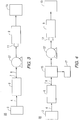
- FIG. 2 shows schematically a VES power generation system 20 in accordance with certain embodiments of the invention.
- FIG. 2 includes the tank 2, stream of compressed air 4, pressure regulator 6, outlet 7, stream of lower pressure compressed air 8, eductor 9, eductor nozzle 11 and control room 13 as shown in FIG. 1 .
- the pressure regulator 6 reduces the pressure of the incoming stream of compressed air 4 such that the stream of lower pressure compressed air 8 passes through the outlet 7.
- FIG. 2 includes an air turbine 15 and an alternator/generator 17. These two components are provided upstream of the eductor 9 and eductor nozzle 11.
- the stream of lower pressure compressed air 8 exits the pressure regulator outlet 7 and is fed into the air turbine 15 and alternator/generator 17 to convert stored energy in the compressed air into useful energy, e.g., power, which can be used for coping functions during an accident scenario in a nuclear reactor power plant when the VES is activated.
- the lower pressure compressed air 8 has a pressure that is essentially equal to that required by the air turbine 15. The recovery and conversion of the stored energy to useful energy in the VES is accomplished while meeting the design requirements of the VES.
- the pressure of the compressed air can vary. In certain embodiments, the compressed air is initially at a pressure of about 22.980 kPa (3333 psig), e.g., in the tank 2.
- the air is adiabatically and isentropically expanded from this initial pressure to a final pressure of about 1.340 kPa (200 psig).
- This expansion occurs through the air turbine 15 and therefore, the pressure of about 1.340 kPa (200 psig) is downstream of the air turbine 15.
- a secondary pressure regulator (not shown) may be employed to further reduce the pressure to that required by the eductor 9 or other component positioned downstream of the air turbine 15, such as an air-driven pump (as shown in FIG. 3 ).
- the secondary pressure regulator (not shown) may be positioned between the air turbine 15 and the eductor nozzle 11.
- the available energy is estimated by multiplying the difference in enthalpy of the initial and final pressure states by the mass of air that is expanded. The details of this conversion are later provided herein. This energy can be used during the coping period of an accident scenario for a variety of useful functions, such as, but not limited to, charging batteries or powering instrumentation and other equipment.
- FIG. 3 includes the tank 2, stream of compressed air 4, pressure regulator 6, outlet 7, stream of lower pressure compressed air 8, eductor 9, eductor nozzle 11 and control room 13 as shown in FIG. 1 .
- FIG. 3 includes an air-driven pump 27 positioned downstream of the pressure regulator 6 and its outlet 7, and upstream of the eductor 9 and its nozzle 11.
- the pressure regulator 6 is set to deliver the inlet pressure required by the air-driven pump 27 (instead of the air turbine 15 as shown in FIG. 1 ).
- the invention further includes the VES power generation system 30 shown schematically in FIG. 4 , in accordance with certain embodiments.
- FIG. 4 includes the tank 2, stream of compressed air 4, pressure regulator 6, outlet 7, stream of lower pressure compressed air 8, eductor 9, eductor nozzle 11 and control room 13 as shown in FIG. 1 .
- FIG. 4 includes the air turbine 15, the alternator/generator 17 and the air-driven pump 27.
- the air-driven pump 27 is positioned downstream of the air turbine 15 and, upstream of the eductor 9 and its nozzle 11.
- the system will be configured such that either the air turbine 15 exhausts at a pressure that matches the required inlet pressure of the air-driven pump 27, or a secondary pressure regulator (not shown) may be installed between the air turbine 15 and the air-driven pump 27 such that the appropriate inlet pressure to the air-driven pump 27 is achieved.
- the pressure regulator 6 is set to provide a pressure of 830 kPa (120 psig) at its outlet 7 and the eductor nozzle 11 / eductor 9 is designed to operate at 760 kPa (110 psig). In other embodiments, the pressure regulator 6 is set at a significantly higher pressure corresponding to the design/inlet pressure of the air turbine, and the turbine exhaust is at the design/inlet pressure of the air-driven pump. It is understood that additional pressure regulating devices may be included as needed to produce the desired inlet pressures to the air turbine, air-driven pump or eductor.
- This pump can be used, for example, to transport water from on-site storage tanks to locations where it is needed for coping during an accident scenario.
- the stored energy of any substance is equal to the total enthalpy of that substance.
- the total useful energy is the difference between the enthalpy before performing work and the enthalpy at the final condition.
- the initial pressure of the compressed air is a function of the ambient conditions in the air storage tank room.
- the calculated tank pressure at ambient temperatures of 16°C (60°F) and 27°C (80°F) was determined to be 22.980 and 24.160 kPa (3333 and 3504 psig), respectively.
- the pressure of the air at the inlet of the eductor was determined to be 760 kPa (110 psig).
- Equation 3 governs the total energy transfer from any system, wherein ⁇ u 2 2 g c is the change in kinetic energy, g ⁇ z is the change in the potential energy, ⁇ H is the change in the system enthalpy, Q is heat and W s is the work.
- the final enthalpy, H 2 was not readily known but the final pressure was known and it was assumed that the system was completely reversible (isentropic).
- the pressure regulating valve had a minimum inlet pressure of 200 psig (214.7 psia), and it was a reasonable assumption that if the compressed air was expanded to 200 psig, the VES system performance was not affected.
- 214.7 psia 14.8 bar TABLE 2 Pressure 120K 140K 10 bar
- Enthalpy 106.2 kJ/kg
- Enthalpy 130.2 kJ/kg
- Entropy 5.214 kJ/(kg*K)
- Entropy 5.398 kJ/(kg*K) 20 bar
- Enthalpy 85.2 kJ/kg
- Enthalpy 118.5 kJ/kg
- Entropy 4.882 kJ/(kg*K)
- Entropy 5.140 kJ/(kg*K)
- E m air h 1 ⁇ h 2
- Table 3 below provides a listing of typical post accident loads that may be powered by the generation systems and methods of the invention. It is shown from the electric output which is available and these loads that several hours of additional coping time may be provided during a loss of AC power scenario.
- the compressed air Downstream of the pressure regulator, the compressed air was expected to be 120 psig, with a flowrate of 65 ⁇ 5 SCFM.
- the inlet eductor pressure was 110 psig, which did not allow for much opportunity to extract useful energy from the compressed air stream downstream of the pressure regulator.
- the eductor inlet pressure was decreased to ⁇ 95psig, another potential use of the compressed air was investigated. Instead of extracting energy and generating electricity, the relatively lower air pressure was used to power a pneumatic device, e.g., an air-operated diaphragm pump.
- FIG. 5 A representative pump curve is shown in FIG. 5 .
- 65 SCFM of 120 psig pressure inlet air provided approximately 40 gpm of water at a discharge head of approximately 225 feet.
- the air outlet pressure was >95 psig.
- the VES operated for a minimum of 72 hours.
- the total amount of energy contained in the compressed air tanks was found to be 2613.2 MJ.
- Adibatic, isentropic expansion from the expected operating pressure to the design pressure of the pressure regulator had the ability to yield 1489.0 MJ. Assuming an overall electrical generation of 33%, 136.5 kwh of electricity was expected from a compressed air turbine system.
- an air-operated diaphragm pump located downstream of the pressure regulator had the potential to deliver 172,800 gallons of water at a discharge head of ⁇ 225 feet using a representative pump curve.
Landscapes
- Engineering & Computer Science (AREA)
- Physics & Mathematics (AREA)
- General Engineering & Computer Science (AREA)
- Plasma & Fusion (AREA)
- High Energy & Nuclear Physics (AREA)
- Business, Economics & Management (AREA)
- Emergency Management (AREA)
- Jet Pumps And Other Pumps (AREA)
- Electromagnetic Pumps, Or The Like (AREA)
- Other Liquid Machine Or Engine Such As Wave Power Use (AREA)
- Fluid Mechanics (AREA)
- Mechanical Engineering (AREA)
Claims (8)
- Système passive d'habitabilité pour une salle de commande d'une centrale nucléaire, le système comprenant :au moins un réservoir (2) structuré pour stocker de l'air comprimé ;un régulateur de pression (6) structuré pour recevoir l'air comprimé et réduire la pression de l'air comprimé pour produire de l'air comprimé à pression inférieure (8) ;une turbine à air (15) structurée pour recevoir et dépressuriser l'air comprimé à pression inférieure (8), l'air comprimé à pression inférieure (8) correspondant à une pression d'entrée de la turbine à air (15) ;un générateur (17) structuré pour convertir l'air comprimé à pression inférieure (8) en puissance électrique ;un éducteur (9) structuré pour recevoir et distribuer l'air comprimé à pression inférieure (8) dans une salle de commande de la centrale nucléaire ; etde la tuyauterie pour relier le réservoir (2), le régulateur de pression (6), la turbine à air (15), le générateur (17) et réducteur (9),dans lequel le système passive d'habitabilité pour une salle de commande convertit l'énergie stockée de l'air comprimé à pression inférieure (8) en puissance électrique lorsque le système d'habitabilité pour une salle de commande est activé pendant un scénario de perte de toute puissance AC.
- Système passive d'habitabilité pour une salle de commande selon la revendication 1, en outre comprenant une pompe (27) entraînée par l'air.
- Système passive d'habitabilité pour une salle de commande selon la revendication 1, dans lequel la pression maximale de l'air comprimé dans l'au moins un réservoir (2) est d'environ 27,6 MPa (4000 psi).
- Système passive d'habitabilité pour une salle de commande selon la revendication 1, dans lequel la pression minimale dans l'au moins un réservoir (2) est d'environ 22,980 MPa (3333 psi).
- Système passive d'habitabilité pour une salle de commande selon la revendication 1, dans lequel l'air comprimé à pression inférieure (8) est à d'environ 0,83 MPa (120 psi).
- Système passive d'habitabilité pour une salle de commande selon la revendication 2, dans lequel une différence de pression de 0,172 MPa (25 psi) entre l'air comprimé à pression inférieure (8) et la pression nominale de l'éducteur (9) est utilisée pour opérer la pompe (27) entraînée par l'air.
- Procédé pour produire de l'énergie à partir de l'air comprimé dans un système passive d'habitabilité pour une salle de commande activé dans une centrale nucléaire, le procédé comprenant :pressuriser de l'air comprimé dans au moins un réservoir de stockage (2) ;faire passer l'air comprimé (4) à travers un régulateur de pression (6) pour produire un courant d'air comprimé à pression inférieure (8) ; etfournir l'air comprimé à pression inférieure (8) à une turbine à air (15) et un générateur (17) pour produire de l'énergie.
- Procédé selon la revendication 7, en outre comprenant une pompe (27) entraînée par l'air.
Applications Claiming Priority (2)
| Application Number | Priority Date | Filing Date | Title |
|---|---|---|---|
| US13/760,165 US9275767B2 (en) | 2013-02-06 | 2013-02-06 | Systems and methods for generating power employing VES air supply stored energy |
| PCT/US2013/076360 WO2014123630A1 (fr) | 2013-02-06 | 2013-12-19 | Systèmes et méthodes de production d'électricité utilisant l'énergie stockée d'une alimentation en air ves |
Publications (3)
| Publication Number | Publication Date |
|---|---|
| EP2954532A1 EP2954532A1 (fr) | 2015-12-16 |
| EP2954532A4 EP2954532A4 (fr) | 2016-09-07 |
| EP2954532B1 true EP2954532B1 (fr) | 2018-06-27 |
Family
ID=51258072
Family Applications (1)
| Application Number | Title | Priority Date | Filing Date |
|---|---|---|---|
| EP13874435.4A Not-in-force EP2954532B1 (fr) | 2013-02-06 | 2013-12-19 | Systèmes et méthodes de production d'électricité utilisant l'énergie stockée d'une alimentation en air ves |
Country Status (7)
| Country | Link |
|---|---|
| US (1) | US9275767B2 (fr) |
| EP (1) | EP2954532B1 (fr) |
| JP (1) | JP6275749B2 (fr) |
| KR (2) | KR102099492B1 (fr) |
| CN (1) | CN104919530B (fr) |
| ES (1) | ES2686603T3 (fr) |
| WO (1) | WO2014123630A1 (fr) |
Families Citing this family (4)
| Publication number | Priority date | Publication date | Assignee | Title |
|---|---|---|---|---|
| CN104700907B (zh) * | 2015-03-25 | 2017-11-10 | 中广核研究院有限公司 | 核电厂主控室非能动制冷空调系统 |
| US10283227B2 (en) * | 2015-12-10 | 2019-05-07 | Westinghouse Electric Company Llc | System usable in nuclear environment for providing breathing gas |
| CN116465052A (zh) * | 2023-04-11 | 2023-07-21 | 中国核电工程有限公司 | 一种核电厂主控室用风幕装置 |
| US12215610B1 (en) * | 2023-10-03 | 2025-02-04 | Google Llc | Air turbine energy recapture system |
Citations (1)
| Publication number | Priority date | Publication date | Assignee | Title |
|---|---|---|---|---|
| JP2008089285A (ja) * | 2006-10-05 | 2008-04-17 | Toshiba Corp | 原子力発電所建家の換気空調設備及び換気空調方法 |
Family Cites Families (14)
| Publication number | Priority date | Publication date | Assignee | Title |
|---|---|---|---|---|
| FR2475679A1 (fr) * | 1980-02-12 | 1981-08-14 | Calhene | Circuit de ventilation et de filtration du milieu contenu dans une enceinte etanche |
| US4995892A (en) * | 1989-12-19 | 1991-02-26 | Ppg Industries, Inc. | Process and apparatus for controlling the thermal environment of glass fiber forming |
| US5108695A (en) | 1991-02-25 | 1992-04-28 | Westinghouse Electric Corp. | Ventilating system for an emergency feedwater enclosure in a nuclear power plant |
| US20060059936A1 (en) | 2004-09-17 | 2006-03-23 | Radke Robert E | Systems and methods for providing cooling in compressed air storage power supply systems |
| US20060207681A1 (en) * | 2005-03-18 | 2006-09-21 | Gary Purington | Portable fluid pumping station |
| JP4583296B2 (ja) * | 2005-12-14 | 2010-11-17 | 国立大学法人広島大学 | 肌年齢の測定方法及びその装置 |
| KR100792790B1 (ko) * | 2006-08-21 | 2008-01-10 | 한국기계연구원 | 압축공기저장발전시스템 및 이를 이용한 발전방법 |
| US9435552B2 (en) | 2007-12-14 | 2016-09-06 | Ge-Hitachi Nuclear Energy Americas Llc | Air filtration and handling for nuclear reactor habitability area |
| US7819935B2 (en) * | 2007-12-14 | 2010-10-26 | Ge-Hitachi Nuclear Energy Americas Llc | Air filtration for nuclear reactor habitability area |
| US20100307156A1 (en) * | 2009-06-04 | 2010-12-09 | Bollinger Benjamin R | Systems and Methods for Improving Drivetrain Efficiency for Compressed Gas Energy Storage and Recovery Systems |
| US8225900B2 (en) | 2008-04-26 | 2012-07-24 | Domes Timothy J | Pneumatic mechanical power source |
| US20100024445A1 (en) * | 2008-08-04 | 2010-02-04 | Cichanowicz J Edward | Simultaneously providing renewable power and cooling for data center operation |
| US8347628B2 (en) * | 2009-08-18 | 2013-01-08 | Gerard Henry M | Power generation directly from compressed air for exploiting wind and solar power |
| US9091215B2 (en) | 2011-06-28 | 2015-07-28 | General Electric Company | System for ventilating a gas turbine enclosure |
-
2013
- 2013-02-06 US US13/760,165 patent/US9275767B2/en not_active Expired - Fee Related
- 2013-12-19 CN CN201380070998.6A patent/CN104919530B/zh not_active Expired - Fee Related
- 2013-12-19 KR KR1020157024169A patent/KR102099492B1/ko not_active Expired - Fee Related
- 2013-12-19 JP JP2015556007A patent/JP6275749B2/ja not_active Expired - Fee Related
- 2013-12-19 KR KR1020207009587A patent/KR20200038328A/ko not_active Withdrawn
- 2013-12-19 ES ES13874435.4T patent/ES2686603T3/es active Active
- 2013-12-19 EP EP13874435.4A patent/EP2954532B1/fr not_active Not-in-force
- 2013-12-19 WO PCT/US2013/076360 patent/WO2014123630A1/fr not_active Ceased
Patent Citations (1)
| Publication number | Priority date | Publication date | Assignee | Title |
|---|---|---|---|---|
| JP2008089285A (ja) * | 2006-10-05 | 2008-04-17 | Toshiba Corp | 原子力発電所建家の換気空調設備及び換気空調方法 |
Also Published As
| Publication number | Publication date |
|---|---|
| EP2954532A4 (fr) | 2016-09-07 |
| WO2014123630A1 (fr) | 2014-08-14 |
| JP6275749B2 (ja) | 2018-02-07 |
| KR102099492B1 (ko) | 2020-04-09 |
| KR20150115011A (ko) | 2015-10-13 |
| US9275767B2 (en) | 2016-03-01 |
| ES2686603T3 (es) | 2018-10-18 |
| JP2016507056A (ja) | 2016-03-07 |
| CN104919530B (zh) | 2017-05-31 |
| CN104919530A (zh) | 2015-09-16 |
| KR20200038328A (ko) | 2020-04-10 |
| US20140216021A1 (en) | 2014-08-07 |
| EP2954532A1 (fr) | 2015-12-16 |
Similar Documents
| Publication | Publication Date | Title |
|---|---|---|
| US20210156560A1 (en) | Method for removing nitrogen oxides from combustion fumes with on-site generation of ammonia | |
| EP2954532B1 (fr) | Systèmes et méthodes de production d'électricité utilisant l'énergie stockée d'une alimentation en air ves | |
| KR101705657B1 (ko) | 전기 발생 장치 및 방법 | |
| EP3759322B9 (fr) | Systèmes et procédés de production d'énergie utilisant le dioxyde de carbone comme fluide de travail | |
| EP3183433A1 (fr) | Système de production d'énergie et procédé de production d'énergie | |
| KR20150001803A (ko) | 압축 공기 에너지 저장 시스템 | |
| US20160356545A1 (en) | Gas liquefaction method and system | |
| KR20170088932A (ko) | 물로부터 수소 가스 및 산소 가스를 생성하는 태양광 발전 시스템 및 방법 | |
| CN106935284B (zh) | 一种聚变反应堆冷却系统 | |
| US10316825B2 (en) | Non-air compressed gas-based energy storage and recovery system and method | |
| US12071892B2 (en) | Compressed N2 for energy storage | |
| Schastlivtsev et al. | Hydrogen–air energy storage gas-turbine system | |
| EP3102797B1 (fr) | Appareil et procédé de récupération d'énergie destiné à être utilisé dans un système de génération de puissance | |
| CN105756727B (zh) | 一种用于燃气轮机试验台的综合气源系统 | |
| Heo et al. | Exergetic analysis of integrated layout for liquid air energy storage applied to APR1400 using mechanical drive steam turbines | |
| US10683800B2 (en) | Engine | |
| CA2919645A1 (fr) | Systeme d'energie a air comprime | |
| KA | Systems Engineering Approach of Developing Installed DC Power Backup for the APR1400 for Station Black-Out (SBO) Coping. | |
| Oh et al. | Advanced intermediate heat transport loop design configurations for hydrogen production using high temperature nuclear reactors |
Legal Events
| Date | Code | Title | Description |
|---|---|---|---|
| PUAI | Public reference made under article 153(3) epc to a published international application that has entered the european phase |
Free format text: ORIGINAL CODE: 0009012 |
|
| 17P | Request for examination filed |
Effective date: 20150608 |
|
| AK | Designated contracting states |
Kind code of ref document: A1 Designated state(s): AL AT BE BG CH CY CZ DE DK EE ES FI FR GB GR HR HU IE IS IT LI LT LU LV MC MK MT NL NO PL PT RO RS SE SI SK SM TR |
|
| AX | Request for extension of the european patent |
Extension state: BA ME |
|
| DAX | Request for extension of the european patent (deleted) | ||
| A4 | Supplementary search report drawn up and despatched |
Effective date: 20160805 |
|
| RIC1 | Information provided on ipc code assigned before grant |
Ipc: H05K 7/20 20060101ALI20160801BHEP Ipc: F02C 6/16 20060101ALI20160801BHEP Ipc: G21D 3/04 20060101ALI20160801BHEP Ipc: G21D 1/00 20060101AFI20160801BHEP Ipc: G21D 1/02 20060101ALI20160801BHEP |
|
| 17Q | First examination report despatched |
Effective date: 20170703 |
|
| REG | Reference to a national code |
Ref country code: DE Ref legal event code: R079 Ref document number: 602013039559 Country of ref document: DE Free format text: PREVIOUS MAIN CLASS: G21C0009000000 Ipc: G21D0001000000 |
|
| GRAP | Despatch of communication of intention to grant a patent |
Free format text: ORIGINAL CODE: EPIDOSNIGR1 |
|
| RIC1 | Information provided on ipc code assigned before grant |
Ipc: G21D 1/02 20060101ALI20180201BHEP Ipc: G21D 1/00 20060101AFI20180201BHEP Ipc: G21C 1/00 20180101ALI20180201BHEP Ipc: G21K 1/00 20060101ALI20180201BHEP Ipc: G21D 3/04 20060101ALI20180201BHEP Ipc: F24F 7/00 20060101ALI20180201BHEP Ipc: F24F 5/00 20060101ALI20180201BHEP |
|
| INTG | Intention to grant announced |
Effective date: 20180215 |
|
| GRAJ | Information related to disapproval of communication of intention to grant by the applicant or resumption of examination proceedings by the epo deleted |
Free format text: ORIGINAL CODE: EPIDOSDIGR1 |
|
| GRAL | Information related to payment of fee for publishing/printing deleted |
Free format text: ORIGINAL CODE: EPIDOSDIGR3 |
|
| GRAS | Grant fee paid |
Free format text: ORIGINAL CODE: EPIDOSNIGR3 |
|
| INTC | Intention to grant announced (deleted) | ||
| GRAP | Despatch of communication of intention to grant a patent |
Free format text: ORIGINAL CODE: EPIDOSNIGR1 |
|
| GRAA | (expected) grant |
Free format text: ORIGINAL CODE: 0009210 |
|
| INTG | Intention to grant announced |
Effective date: 20180508 |
|
| AK | Designated contracting states |
Kind code of ref document: B1 Designated state(s): AL AT BE BG CH CY CZ DE DK EE ES FI FR GB GR HR HU IE IS IT LI LT LU LV MC MK MT NL NO PL PT RO RS SE SI SK SM TR |
|
| REG | Reference to a national code |
Ref country code: GB Ref legal event code: FG4D |
|
| REG | Reference to a national code |
Ref country code: AT Ref legal event code: REF Ref document number: 1013017 Country of ref document: AT Kind code of ref document: T Effective date: 20180715 |
|
| REG | Reference to a national code |
Ref country code: IE Ref legal event code: FG4D |
|
| REG | Reference to a national code |
Ref country code: DE Ref legal event code: R096 Ref document number: 602013039559 Country of ref document: DE |
|
| REG | Reference to a national code |
Ref country code: SE Ref legal event code: TRGR |
|
| REG | Reference to a national code |
Ref country code: ES Ref legal event code: FG2A Ref document number: 2686603 Country of ref document: ES Kind code of ref document: T3 Effective date: 20181018 |
|
| PG25 | Lapsed in a contracting state [announced via postgrant information from national office to epo] |
Ref country code: FI Free format text: LAPSE BECAUSE OF FAILURE TO SUBMIT A TRANSLATION OF THE DESCRIPTION OR TO PAY THE FEE WITHIN THE PRESCRIBED TIME-LIMIT Effective date: 20180627 Ref country code: NO Free format text: LAPSE BECAUSE OF FAILURE TO SUBMIT A TRANSLATION OF THE DESCRIPTION OR TO PAY THE FEE WITHIN THE PRESCRIBED TIME-LIMIT Effective date: 20180927 Ref country code: BG Free format text: LAPSE BECAUSE OF FAILURE TO SUBMIT A TRANSLATION OF THE DESCRIPTION OR TO PAY THE FEE WITHIN THE PRESCRIBED TIME-LIMIT Effective date: 20180927 Ref country code: LT Free format text: LAPSE BECAUSE OF FAILURE TO SUBMIT A TRANSLATION OF THE DESCRIPTION OR TO PAY THE FEE WITHIN THE PRESCRIBED TIME-LIMIT Effective date: 20180627 |
|
| REG | Reference to a national code |
Ref country code: NL Ref legal event code: MP Effective date: 20180627 |
|
| REG | Reference to a national code |
Ref country code: LT Ref legal event code: MG4D |
|
| PG25 | Lapsed in a contracting state [announced via postgrant information from national office to epo] |
Ref country code: GR Free format text: LAPSE BECAUSE OF FAILURE TO SUBMIT A TRANSLATION OF THE DESCRIPTION OR TO PAY THE FEE WITHIN THE PRESCRIBED TIME-LIMIT Effective date: 20180928 Ref country code: HR Free format text: LAPSE BECAUSE OF FAILURE TO SUBMIT A TRANSLATION OF THE DESCRIPTION OR TO PAY THE FEE WITHIN THE PRESCRIBED TIME-LIMIT Effective date: 20180627 Ref country code: LV Free format text: LAPSE BECAUSE OF FAILURE TO SUBMIT A TRANSLATION OF THE DESCRIPTION OR TO PAY THE FEE WITHIN THE PRESCRIBED TIME-LIMIT Effective date: 20180627 Ref country code: RS Free format text: LAPSE BECAUSE OF FAILURE TO SUBMIT A TRANSLATION OF THE DESCRIPTION OR TO PAY THE FEE WITHIN THE PRESCRIBED TIME-LIMIT Effective date: 20180627 |
|
| REG | Reference to a national code |
Ref country code: AT Ref legal event code: MK05 Ref document number: 1013017 Country of ref document: AT Kind code of ref document: T Effective date: 20180627 |
|
| PG25 | Lapsed in a contracting state [announced via postgrant information from national office to epo] |
Ref country code: NL Free format text: LAPSE BECAUSE OF FAILURE TO SUBMIT A TRANSLATION OF THE DESCRIPTION OR TO PAY THE FEE WITHIN THE PRESCRIBED TIME-LIMIT Effective date: 20180627 |
|
| PG25 | Lapsed in a contracting state [announced via postgrant information from national office to epo] |
Ref country code: CZ Free format text: LAPSE BECAUSE OF FAILURE TO SUBMIT A TRANSLATION OF THE DESCRIPTION OR TO PAY THE FEE WITHIN THE PRESCRIBED TIME-LIMIT Effective date: 20180627 Ref country code: RO Free format text: LAPSE BECAUSE OF FAILURE TO SUBMIT A TRANSLATION OF THE DESCRIPTION OR TO PAY THE FEE WITHIN THE PRESCRIBED TIME-LIMIT Effective date: 20180627 Ref country code: IS Free format text: LAPSE BECAUSE OF FAILURE TO SUBMIT A TRANSLATION OF THE DESCRIPTION OR TO PAY THE FEE WITHIN THE PRESCRIBED TIME-LIMIT Effective date: 20181027 Ref country code: AT Free format text: LAPSE BECAUSE OF FAILURE TO SUBMIT A TRANSLATION OF THE DESCRIPTION OR TO PAY THE FEE WITHIN THE PRESCRIBED TIME-LIMIT Effective date: 20180627 Ref country code: EE Free format text: LAPSE BECAUSE OF FAILURE TO SUBMIT A TRANSLATION OF THE DESCRIPTION OR TO PAY THE FEE WITHIN THE PRESCRIBED TIME-LIMIT Effective date: 20180627 Ref country code: PL Free format text: LAPSE BECAUSE OF FAILURE TO SUBMIT A TRANSLATION OF THE DESCRIPTION OR TO PAY THE FEE WITHIN THE PRESCRIBED TIME-LIMIT Effective date: 20180627 Ref country code: SK Free format text: LAPSE BECAUSE OF FAILURE TO SUBMIT A TRANSLATION OF THE DESCRIPTION OR TO PAY THE FEE WITHIN THE PRESCRIBED TIME-LIMIT Effective date: 20180627 |
|
| PG25 | Lapsed in a contracting state [announced via postgrant information from national office to epo] |
Ref country code: SM Free format text: LAPSE BECAUSE OF FAILURE TO SUBMIT A TRANSLATION OF THE DESCRIPTION OR TO PAY THE FEE WITHIN THE PRESCRIBED TIME-LIMIT Effective date: 20180627 Ref country code: IT Free format text: LAPSE BECAUSE OF FAILURE TO SUBMIT A TRANSLATION OF THE DESCRIPTION OR TO PAY THE FEE WITHIN THE PRESCRIBED TIME-LIMIT Effective date: 20180627 |
|
| REG | Reference to a national code |
Ref country code: DE Ref legal event code: R097 Ref document number: 602013039559 Country of ref document: DE |
|
| PLBE | No opposition filed within time limit |
Free format text: ORIGINAL CODE: 0009261 |
|
| STAA | Information on the status of an ep patent application or granted ep patent |
Free format text: STATUS: NO OPPOSITION FILED WITHIN TIME LIMIT |
|
| PG25 | Lapsed in a contracting state [announced via postgrant information from national office to epo] |
Ref country code: DK Free format text: LAPSE BECAUSE OF FAILURE TO SUBMIT A TRANSLATION OF THE DESCRIPTION OR TO PAY THE FEE WITHIN THE PRESCRIBED TIME-LIMIT Effective date: 20180627 |
|
| 26N | No opposition filed |
Effective date: 20190328 |
|
| REG | Reference to a national code |
Ref country code: CH Ref legal event code: PL |
|
| PG25 | Lapsed in a contracting state [announced via postgrant information from national office to epo] |
Ref country code: SI Free format text: LAPSE BECAUSE OF FAILURE TO SUBMIT A TRANSLATION OF THE DESCRIPTION OR TO PAY THE FEE WITHIN THE PRESCRIBED TIME-LIMIT Effective date: 20180627 Ref country code: LU Free format text: LAPSE BECAUSE OF NON-PAYMENT OF DUE FEES Effective date: 20181219 Ref country code: MC Free format text: LAPSE BECAUSE OF FAILURE TO SUBMIT A TRANSLATION OF THE DESCRIPTION OR TO PAY THE FEE WITHIN THE PRESCRIBED TIME-LIMIT Effective date: 20180627 |
|
| REG | Reference to a national code |
Ref country code: IE Ref legal event code: MM4A |
|
| PG25 | Lapsed in a contracting state [announced via postgrant information from national office to epo] |
Ref country code: IE Free format text: LAPSE BECAUSE OF NON-PAYMENT OF DUE FEES Effective date: 20181219 |
|
| PG25 | Lapsed in a contracting state [announced via postgrant information from national office to epo] |
Ref country code: AL Free format text: LAPSE BECAUSE OF FAILURE TO SUBMIT A TRANSLATION OF THE DESCRIPTION OR TO PAY THE FEE WITHIN THE PRESCRIBED TIME-LIMIT Effective date: 20180627 |
|
| PG25 | Lapsed in a contracting state [announced via postgrant information from national office to epo] |
Ref country code: LI Free format text: LAPSE BECAUSE OF NON-PAYMENT OF DUE FEES Effective date: 20181231 Ref country code: CH Free format text: LAPSE BECAUSE OF NON-PAYMENT OF DUE FEES Effective date: 20181231 |
|
| PG25 | Lapsed in a contracting state [announced via postgrant information from national office to epo] |
Ref country code: MT Free format text: LAPSE BECAUSE OF NON-PAYMENT OF DUE FEES Effective date: 20181219 |
|
| PG25 | Lapsed in a contracting state [announced via postgrant information from national office to epo] |
Ref country code: TR Free format text: LAPSE BECAUSE OF FAILURE TO SUBMIT A TRANSLATION OF THE DESCRIPTION OR TO PAY THE FEE WITHIN THE PRESCRIBED TIME-LIMIT Effective date: 20180627 |
|
| PG25 | Lapsed in a contracting state [announced via postgrant information from national office to epo] |
Ref country code: PT Free format text: LAPSE BECAUSE OF FAILURE TO SUBMIT A TRANSLATION OF THE DESCRIPTION OR TO PAY THE FEE WITHIN THE PRESCRIBED TIME-LIMIT Effective date: 20180627 |
|
| PG25 | Lapsed in a contracting state [announced via postgrant information from national office to epo] |
Ref country code: HU Free format text: LAPSE BECAUSE OF FAILURE TO SUBMIT A TRANSLATION OF THE DESCRIPTION OR TO PAY THE FEE WITHIN THE PRESCRIBED TIME-LIMIT; INVALID AB INITIO Effective date: 20131219 Ref country code: CY Free format text: LAPSE BECAUSE OF FAILURE TO SUBMIT A TRANSLATION OF THE DESCRIPTION OR TO PAY THE FEE WITHIN THE PRESCRIBED TIME-LIMIT Effective date: 20180627 Ref country code: MK Free format text: LAPSE BECAUSE OF NON-PAYMENT OF DUE FEES Effective date: 20180627 |
|
| PGFP | Annual fee paid to national office [announced via postgrant information from national office to epo] |
Ref country code: FR Payment date: 20201223 Year of fee payment: 8 Ref country code: GB Payment date: 20201222 Year of fee payment: 8 Ref country code: SE Payment date: 20201230 Year of fee payment: 8 |
|
| PGFP | Annual fee paid to national office [announced via postgrant information from national office to epo] |
Ref country code: BE Payment date: 20201222 Year of fee payment: 8 |
|
| PGFP | Annual fee paid to national office [announced via postgrant information from national office to epo] |
Ref country code: ES Payment date: 20210108 Year of fee payment: 8 Ref country code: DE Payment date: 20201222 Year of fee payment: 8 |
|
| REG | Reference to a national code |
Ref country code: DE Ref legal event code: R119 Ref document number: 602013039559 Country of ref document: DE |
|
| REG | Reference to a national code |
Ref country code: SE Ref legal event code: EUG |
|
| GBPC | Gb: european patent ceased through non-payment of renewal fee |
Effective date: 20211219 |
|
| REG | Reference to a national code |
Ref country code: BE Ref legal event code: MM Effective date: 20211231 |
|
| PG25 | Lapsed in a contracting state [announced via postgrant information from national office to epo] |
Ref country code: SE Free format text: LAPSE BECAUSE OF NON-PAYMENT OF DUE FEES Effective date: 20211220 Ref country code: GB Free format text: LAPSE BECAUSE OF NON-PAYMENT OF DUE FEES Effective date: 20211219 Ref country code: DE Free format text: LAPSE BECAUSE OF NON-PAYMENT OF DUE FEES Effective date: 20220701 |
|
| PG25 | Lapsed in a contracting state [announced via postgrant information from national office to epo] |
Ref country code: FR Free format text: LAPSE BECAUSE OF NON-PAYMENT OF DUE FEES Effective date: 20211231 Ref country code: BE Free format text: LAPSE BECAUSE OF NON-PAYMENT OF DUE FEES Effective date: 20211231 |
|
| REG | Reference to a national code |
Ref country code: ES Ref legal event code: FD2A Effective date: 20230327 |
|
| PG25 | Lapsed in a contracting state [announced via postgrant information from national office to epo] |
Ref country code: ES Free format text: LAPSE BECAUSE OF NON-PAYMENT OF DUE FEES Effective date: 20211220 |