EP2954538B1 - Überspannungsschutzgerät mit thermischer abtrennvorrichtung - Google Patents
Überspannungsschutzgerät mit thermischer abtrennvorrichtung Download PDFInfo
- Publication number
- EP2954538B1 EP2954538B1 EP14701766.9A EP14701766A EP2954538B1 EP 2954538 B1 EP2954538 B1 EP 2954538B1 EP 14701766 A EP14701766 A EP 14701766A EP 2954538 B1 EP2954538 B1 EP 2954538B1
- Authority
- EP
- European Patent Office
- Prior art keywords
- overvoltage protection
- slide
- spring
- protection device
- contact lug
- Prior art date
- Legal status (The legal status is an assumption and is not a legal conclusion. Google has not performed a legal analysis and makes no representation as to the accuracy of the status listed.)
- Not-in-force
Links
Images


Classifications
-
- H—ELECTRICITY
- H01—ELECTRIC ELEMENTS
- H01H—ELECTRIC SWITCHES; RELAYS; SELECTORS; EMERGENCY PROTECTIVE DEVICES
- H01H37/00—Thermally-actuated switches
- H01H37/74—Switches in which only the opening movement or only the closing movement of a contact is effected by heating or cooling
- H01H37/76—Contact member actuated by melting of fusible material, actuated due to burning of combustible material or due to explosion of explosive material
- H01H37/761—Contact member actuated by melting of fusible material, actuated due to burning of combustible material or due to explosion of explosive material with a fusible element forming part of the switched circuit
-
- H—ELECTRICITY
- H01—ELECTRIC ELEMENTS
- H01C—RESISTORS
- H01C7/00—Non-adjustable resistors formed as one or more layers or coatings; Non-adjustable resistors made from powdered conducting material or powdered semi-conducting material with or without insulating material
- H01C7/10—Non-adjustable resistors formed as one or more layers or coatings; Non-adjustable resistors made from powdered conducting material or powdered semi-conducting material with or without insulating material voltage responsive, i.e. varistors
- H01C7/12—Overvoltage protection resistors; Arresters
- H01C7/126—Means for protecting against excessive pressure or for disconnecting in case of failure
-
- H—ELECTRICITY
- H01—ELECTRIC ELEMENTS
- H01H—ELECTRIC SWITCHES; RELAYS; SELECTORS; EMERGENCY PROTECTIVE DEVICES
- H01H37/00—Thermally-actuated switches
- H01H37/02—Details
- H01H37/08—Indicators; Distinguishing marks
-
- H—ELECTRICITY
- H01—ELECTRIC ELEMENTS
- H01T—SPARK GAPS; OVERVOLTAGE ARRESTERS USING SPARK GAPS; SPARKING PLUGS; CORONA DEVICES; GENERATING IONS TO BE INTRODUCED INTO NON-ENCLOSED GASES
- H01T1/00—Details of spark gaps
- H01T1/12—Means structurally associated with spark gap for recording operation thereof
-
- H—ELECTRICITY
- H01—ELECTRIC ELEMENTS
- H01T—SPARK GAPS; OVERVOLTAGE ARRESTERS USING SPARK GAPS; SPARKING PLUGS; CORONA DEVICES; GENERATING IONS TO BE INTRODUCED INTO NON-ENCLOSED GASES
- H01T1/00—Details of spark gaps
- H01T1/14—Means structurally associated with spark gap for protecting it against overload or for disconnecting it in case of failure
-
- H—ELECTRICITY
- H01—ELECTRIC ELEMENTS
- H01H—ELECTRIC SWITCHES; RELAYS; SELECTORS; EMERGENCY PROTECTIVE DEVICES
- H01H37/00—Thermally-actuated switches
- H01H37/74—Switches in which only the opening movement or only the closing movement of a contact is effected by heating or cooling
- H01H37/76—Contact member actuated by melting of fusible material, actuated due to burning of combustible material or due to explosion of explosive material
- H01H37/761—Contact member actuated by melting of fusible material, actuated due to burning of combustible material or due to explosion of explosive material with a fusible element forming part of the switched circuit
- H01H2037/762—Contact member actuated by melting of fusible material, actuated due to burning of combustible material or due to explosion of explosive material with a fusible element forming part of the switched circuit using a spring for opening the circuit when the fusible element melts
-
- H—ELECTRICITY
- H01—ELECTRIC ELEMENTS
- H01H—ELECTRIC SWITCHES; RELAYS; SELECTORS; EMERGENCY PROTECTIVE DEVICES
- H01H2207/00—Connections
- H01H2207/022—Plug
-
- H—ELECTRICITY
- H01—ELECTRIC ELEMENTS
- H01H—ELECTRIC SWITCHES; RELAYS; SELECTORS; EMERGENCY PROTECTIVE DEVICES
- H01H2235/00—Springs
- H01H2235/01—Spiral spring
Definitions
- the invention relates to an overvoltage protection device which has at least one overvoltage protection unit with at least one contact lug and a mechanical disconnection device activated in the event of thermal overload, wherein the mechanical separation device comprises a connection element which can be moved from a closed slide to a current-interrupting or potential-separating position by means of a slide biased by a spring force is, according to the preamble of claim 1.
- Overvoltage protection devices with thermal cut-off device have been part of the known state of the art for many years ( DE102007006617B3 ).
- the object of a separating device is, in the case of an inadmissible heating of the overvoltage protection unit, for example a varistor, to safely disconnect it from the network before destruction of the arrester occurs.
- the utility model DE 295 19 313 U1 shows an overvoltage protection device with a separation device on a thermal basis, wherein the separation device is positioned separately from the actual varistor via a partition wall.
- the surge current carrying capacity of such a separation device is under current aspects too low and it is the local solder joint exposed to a constant spring biasing force.
- the previously known DE 2 220 264 A relates to an overheat protection or display device in which the actuation is blocked by means of a temperature-dependent holding element and when a predetermined temperature is reached as a result of the melting of the holding element, a slide is actuated.
- the DE 1 515 019 A discloses a temperature limiter in which two leaf springs are soldered together by means of a soldering when a certain temperature melting solder, and which finds particular application in fan heaters.
- the object is achieved to provide an advanced surge protection device activated in thermal overload case mechanical separation device, the solder joint of the connection elements, which is opened in Abtrennfall not constantly subject to the action of a mechanical force-side load.
- the previously known solution has a high surge current carrying capacity, wherein the contact pressure for the discharge process is produced by the surge current itself.
- the separation device after DE 10 2007 042 991 B4 is realized in such a way that the supply to the voltage-limiting overvoltage protection units, in particular varistors, is formed by two conductor sections through which surge current flows in the same direction, which run parallel in the end region and pass into a common connection point, which is secured by a solder.
- a disadvantage of the solution DE 10 2007 042 991 B4 is the fact that the slider is functionally coupled with the optical signaling of the slide position and thus an indication of the functional properties of the separating device. For this reason, therefore, the slider must be constructively designed so that it has a flat as possible, color differentiated display surface to make the respective functional state of the corresponding surge protection device. Furthermore, the direction of movement of the slider for the purpose of separating the preferably used varistors in case of overload is predetermined, so that the position of a viewing window for detecting the state of motion of the slider is constructively determined, which for example represents a disadvantage in reducing the size of corresponding overvoltage protection devices.
- an object of the invention to provide an advanced surge protection device with at least one surge protection unit which has activated or activated in thermal overload mechanical separation device, on the one hand has the positive effects in terms of current flow and associated force effects in surge current case and beyond functional separation of a visual indication of the functional state of the overvoltage protection units used allows necessary for the actual separator slide and its path of movement. Furthermore, the possibility is to be created to integrate a telecommunication device for the condition monitoring of the overvoltage protection unit in the designed in particular as a plug-in surge protection device so that only a minimal space is required and given no significant mechanical stress secured with a solder or a thermally releasable adhesive thermal separation point is.
- an overvoltage protection device which has at least one overvoltage protection unit, in particular a varistor, wherein the overvoltage protection unit has at least one contact lug.
- the overvoltage protection device further comprises a disconnection device activated in the event of thermal overload, the disconnection device again having a connection element which can be moved from a closed to a current-interrupting or potential-separating position by means of a spring-biased slide, the connection element consisting of a pair of current-dividing metallic straps, whose directed to the contact lug of the overvoltage protection unit ends run parallel and record in their midst the respective contact lug of the overvoltage protection unit.
- the closed position between the connection element and the contact lug in the region of the parallel ends of the stirrups is secured by a solder or a thermally releasable adhesive or the like means.
- the contact lugs of the overvoltage protection unit facing away from the ends of the bracket are, including a free space connected to each other and have in the course a section for external connection parts, wherein in the free space of the mentioned slider is used with biasing spring, so that the spring bias is oriented in the direction of the contact lug of the overvoltage protection unit ,
- the pusher preferably has a wedge shape and / or portions of the stirrups form an inclined surface for generating a force component on the parallel ends of the stirrups during slide movement such that they move laterally away from the contact lug.
- the ends facing the contact lug form at least one of the brackets a stop for a pivotable about an axis Visual display, wherein the pivoting movement is released when using the slider, the parallel ends of the stirrups laterally move away from the contact lug.
- the position of the aforementioned axis can be perpendicular to the path of movement of the slider, whereby extended design options for the arrangement of the display are given and ultimately the path of movement of the slider is decoupled from the movement or Verschwenkweg the visual display and separated.
- the pivotable visual display on a ratchet extension and a signaling extension wherein the signaling extension merges into a display area with color coding.
- the display surface may in this case have an arcuate surface course to comply with respect to a viewing window to this depending on the pivoting situation an approximately equal distance.
- each surge protection device of the pawl extension In undisturbed operation of the respective surge protection unit in each surge protection device of the pawl extension is at the stop of the at least one bracket, i.
- the bracket blocks the movement of the pawl and swivel display.
- the abovementioned stop can be formed as a molded or integral nose relative to the corresponding end of the bracket. Since the bracket used for the separating device preferably consist of a metallic stamped and bent part, the desired formation of the nose can be easily realized during the punching process and without technological effort.
- the pivotable display is by means of a spring element, in particular this designed as a spring bar, under bias, such that when released pawl extension, the spring element moves the pivotable display in a predetermined pivot position, such that an example applied to the display indicator color "red" in the area reaches the mentioned viewing window and signals the disturbance or separation process.
- a spring element in particular this designed as a spring bar, under bias, such that when released pawl extension, the spring element moves the pivotable display in a predetermined pivot position, such that an example applied to the display indicator color "red" in the area reaches the mentioned viewing window and signals the disturbance or separation process.
- the biasing spring element for the pivotable display also keeps it in the appropriate position after completion of separation, i. Even with mechanical manipulations such as turning, shaking or the like then the red color coding is retained in the window.
- a support body is provided for the overvoltage protection device, which can be realized as a plug-in part, which accommodates a remote-control contact slide in a bottom section.
- the displacement for the remote contact slide is blocked or released by a lateral approach of the Abtrennschiebers depending on the position thereof.
- the telecommunications contact slide is in this case under spring tension, wherein the spring force vector has no force component in the direction of the parallel ends of the bracket of the separating device for lateral movement away from the contact lug.
- Ausgestaltend has the support body lateral guide surfaces with locking lugs or recesses for fixing the housing with viewing window.
- the housing has on its corresponding side surfaces complementary locking recesses or locking projections.
- a cavity for receiving one end of the biasing spring is inserted in the movable slide for the separating device in its longitudinal direction, so that the spring is held securely.
- the complementary end of the spring may be guided by a rivet which simultaneously serves to connect a portion of the metallic brackets to an outer terminal part. Spot welding is also possible.
- the parallel ends of the stirrups can, as already mentioned, be fixed in position by means of a solder or a thermal adhesive, however, they are designed in such a way that they tend to disperse during the separation process by means of a mechanical prestress.
- the overvoltage protection unit accommodated in the overvoltage protection device in particular a varistor, can be connected to the device via a screw fastening Supporting body are connected to prevent external forces acting on the electrically relevant contact points.
- This screw connection also reduces external forces acting on the electrical connection points including the thermal separation point, for example by transport or by other force effects such as vibration or the like.
- the above-mentioned functional separation of visual display and actual separator with slider further has the advantage that the separation process is not hindered by a possible blockage of the movement of the display.
- the operation for the telecommunications contact and the visual display can also be done a very individual dimensioning of the required spring biasing forces.
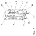
- a varistor 7 can be seen as an overvoltage protection unit used.
- the varistor 7 is connected by means of a tab and a screw 15 to an extension of the support body 11th fixed, this extension at the same time a pivot axis 10 for a visual display 17 (see Fig. 2 or 3 ) can form.
- the connecting element forming the separating device consists of a pair of current-dividing metallic stirrups 1, 1 'whose ends directed towards a contact lug 14 run parallel and which receive the respective contact lug 14 in their middle.
- the closed position between the connection elements and the contact lug 14 is secured in the region of the parallel ends of the brackets 1, 1 'by a solder 3 or a thermally releasable adhesive or the like means.
- the in Fig. 5 recognizable free space is the in Fig. 1 apparent slide 4 with biasing spring 2 (see Fig. 3 ) used.
- the spring preload is oriented here in the direction of the contact lug 14 of the overvoltage protection unit 7.
- the slider 4 has a wedge shape. Additionally or alternatively, corresponding portions of the stirrups 1, 1 'forming an inclined surface are designed to produce a force component on the parallel ends of the stirrups 1, 1' when the slider is moved, so that they move laterally away from the contact lug 14.
- the reference numeral 9 in the Fig. 5 indicates an integrally formed, bent plug connection, which then the connection part 13 according to Fig. 1 forms.
- FIG. 2 now shows further details of the device according to the invention, in particular with respect to the slide 4 functionally separate visual display 17 with bar spring 8, the signaling extension 19 and the pawl extension 18th
- the shows Fig. 2 the slide 16 for the telecommunications contact together with a projection 24 of the slider 4, which serves as a stop for the slider 16 of the telecommunications contact.
- Guide surfaces 25, which are lateral part of the support body 11, in the example shown, comprise a latching nose, which enter into a connection with a complementary latching recess of the housing 6 and thus fix the housing 6 to the support body 11 (see FIG Fig. 4 ).
- the movement path of the slider 4 in Abtrennfall is symbolized by an arrow.
- the movement path of the pivotable display 17 is indicated by arrow, wherein the reference numeral 20, a display surface is marked, which symbolizes the respective functional state (open / detached).
- connection - fault is based on the illustration below Fig. 3 comprehensibly. It can be seen here that with the help of the slider 4, the lateral movement of the bracket 1, 1 'has taken place. In this regard, the pivoting of the pivotable display 17 is released. The rod-shaped spring 8 then causes the corresponding pivoting movement in the example shown the Fig. 3 , left picture part to the right. In the viewing window 21 (see Fig. 4 ), the corresponding, eg red marked field of the visual display is then recognizable.
- the Fig. 4 shows a frontal view of the device according to the invention with teilwegbroken case 6, viewing window 21 and the other functionally essential components, in the state of functional overvoltage protection unit used in the device, ie the varistor there 7.
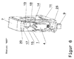
- Fig. 6 as a detailed illustration of the position of the slide 4 in the separation case can further recognize that the slide 4 in its upper slide part in two gear-like ends passes. These two gear-like ends have in the region of their gear ground, ie in the space between the teeth, a portion which is adapted to laterally surround the contact lug 14 and quasi partitioned so that an effective isolation is given in Abtrennfall and the ignition of an arc between the bracket 1, 1 'and the contact lug 14 is securely avoided.
- the tooth height of the gear-like ends of the slider 4 is formed according to the relevant height dimension of the contact lug 14.
- the slider for the telecommunications contact 16 may Fig. 7 move left part of the image to the right, under the action of the spring 26 which is inserted in the slider 16.
- the contact lug 14 facing ends of at least one of the bracket 1, 1 ' form a stop for the pivotable about the axis 10 display 17. The pivoting movement is then released when using the slider 4, the parallel ends of the bracket 1, 1' laterally move away from the contact lug 14.
- the pivotable display 17 has the pawl extension 18 shown and a signaling extension 19, which merges into the display surface 20 with the corresponding color coding.
- the pawl extension 18 is located in undisturbed operation of the surge protection unit 7 at the stop of the at least one bracket 1, 1 '.
- the stop can be like in the Fig. 5 and 7 be formed as a molded or integral nose 22.
- the pivotable display 17 is held by means of a spring bar 8 under bias.
- the support body 11 shown in the figures has in its bottom portion 23 the telecommunications contact slide 16, wherein the displacement from the lateral projection 24 of the slider 4 is blocked or released depending on the position of the slide 4.
- the spring 26 Under bias is also the telecommunications contact slide 16, in this regard, the spring 26 is inserted into the slide and is supported against a corresponding region in the bottom portion 23 of the support body 11. However, the spring bias exerts no force component in the direction of the parallel ends of the strap 1,1 'for lateral movement away from the contact lug 14. In this regard, therefore, the separation point is not subjected to unnecessary mechanical fatigue loads or forces.
- the cavity in the slide 4 for receiving the biasing spring 2 of the slider is in the illustration of Fig. 3 , Left picture part recognizable, wherein the opposite end of the coil spring from a stamping or a rivet head 28 (see Fig. 5 ) is guided.
Landscapes
- Engineering & Computer Science (AREA)
- Microelectronics & Electronic Packaging (AREA)
- Physics & Mathematics (AREA)
- Electromagnetism (AREA)
- Chemical & Material Sciences (AREA)
- Combustion & Propulsion (AREA)
- Fuses (AREA)
Description
- Die Erfindung betrifft ein Überspannungsschutzgerät, welches mindestens eine Überspannungsschutzeinheit mit mindestens einer Kontaktfahne sowie eine im thermischen Überlastfall aktivierte mechanische Abtrennvorrichtung aufweist, wobei die mechanische Abtrennvorrichtung ein Anschlusselement umfasst, welches mittels einem durch eine Federkraft vorgespannten Schieber von einer geschlossenen in eine stromunterbrechende oder potentialtrennende Lage bewegbar ist, gemäß Oberbegriff des Patentanspruchs 1.
- Überspannungsschutzgeräte mit thermischer Abtrennvorrichtung gehören seit vielen Jahren zum bekannten Stand der Technik (
DE102007006617B3 ). Aufgabe einer Abtrennvorrichtung ist es, im Fall einer unzulässigen Erwärmung der Überspannungsschutzeinheit, z.B. eines Varistors, diesen sicher vom Netz zu trennen, bevor eine Zerstörung des Ableiters eintritt. - Aus der
EP 0 987 803 B1 oder derEP 0 905 839 B1 sind Abtrennvorrichtungen bekannt, die einen massiven Schieber umfassen. Der entsprechende Schieber steht unter Federvorspannung und schützt je einen Varistor vor einer unzulässigen thermischen Erwärmung. Die Geschlossenposition der entsprechenden Anschlusselemente wird von einem Lot gesichert. Dieses Lot ist der ständigen Federvorspannkraft, die über den Schieber übertragen wird, ausgesetzt, was einen wesentlichen Nachteil darstellt. Je nach der Leistungsfähigkeit, d.h. der gewünschten Stromtragfähigkeit, sind mehrere Abtrennvorrichtungen erforderlich, was einen kostenseitigen Nachteil darstellt. Es hat sich darüber hinaus gezeigt, dass bei den vorgenannten Lösungen des Standes der Technik beim Abtrennvorgang und der Bewegungsverlagerung des Schiebers Lotteilchen oder Lotpartikel unter Bildung von Lotfäden mitgerissen werden, mit der Folge einer nicht ausreichenden elektrischen Trennung. - Das Gebrauchsmuster
DE 295 19 313 U1 zeigt ein Überspannungsschutzgerät mit einer Abtrennvorrichtung auf thermischer Basis, wobei über eine Abtrennwand die Abtrennvorrichtung vom eigentlichen Varistor separat positioniert ist. Die Stoßstromtragfähigkeit einer solchen Abtrennvorrichtung ist unter heutigen Aspekten zu gering und es ist die dortige Lötstelle einer ständigen Federvorspannkraft ausgesetzt. - Die vorbekannte
DE 2 220 264 A betrifft eine Überhitzungsschutz- oder Anzeigevorrichtung, bei der die Betätigung mittels eines temperaturabhängigen Halteelements blockiert und bei Erreichen einer vorbestimmten Temperatur infolge des Schmelzens des Halteelements ein Schieber betätigt wird. - Die
DE 1 515 019 A offenbart einen Temperaturbegrenzer, bei dem zwei Blattfedern mittels eines bei Erreichen einer bestimmten Temperatur schmelzenden Lotes miteinander verlötet sind, und der speziell bei Heizlüftern Anwendung findet. - Bei der gattungsbildenden
DE 10 2007 042 991 B4 wird die Aufgabe gelöst, ein weiterentwickeltes Überspannungsschutzgerät mit im thermischen Überlastfall aktivierter mechanischer Abtrennvorrichtung anzugeben, wobei die Lotverbindungsstelle der Anschlusselemente, die im Abtrennfall geöffnet wird, nicht ständig der Einwirkung einer mechanischen kraftseitigen Belastung unterliegen soll. Darüber hinaus weist die vorbekannte Lösung eine hohe Stoßstromtragfähigkeit auf, wobei der Kontaktdruck für den Ableitvorgang durch den Stoßstrom selbst produziert wird. Die Abtrennvorrichtung nachDE 10 2007 042 991 B4 ist so realisiert, dass die Zuführung zu den spannungsbegrenzenden Überspannungsschutzeinheiten, insbesondere Varistoren, durch zwei vom Stoßstrom in gleicher Richtung durchflossene Leiterabschnitte gebildet wird, die im Endbereich parallel verlaufen und in eine gemeinsame Verbindungsstelle übergehen, welche von einem Lot gesichert ist. Durch den parallelen Stromfluss und die damit verbundenen Kraftwirkungen im Stoßstromfall ziehen sich die entsprechenden Abschnitte der Leiter bzw. Bügel an und bewirken zu diesem Zeitpunkt die gewünschte Erhöhung der Kontaktkraft an der Lotverbindungsstelle. Damit wird es möglich, die Lotstelle lediglich zur Fixierung der Abschnitte der Bügel auszulegen, was es gestattet, die mechanische Dimensionierung der Lotstelle auf ein absolutes Minimum zu beschränken und diese damit besonders thermisch sensibel auszuführen. Die Feder der diesbezüglichen Abtrennvorrichtung, deren Aufgabe darin besteht, im Fall des Aufschmelzens der Lotstelle einen Schieber zwischen die Strombahnen zu verlagern und damit den Stromkreis zu unterbrechen, kann mit geringerer Federkraft ausgeführt werden, so dass eine niedrige Dauerbelastung der Lotstelle die Folge ist. Da der Schieber im Abtrennfall direkt in die Lotstelle hinein fährt, werden negative Auswirkungen beim Abtrennvorgang unterbunden und eine sichere, spannungsfreie Trennung erreicht. - Nachteilig bei der Lösung nach
DE 10 2007 042 991 B4 ist die Tatsache, dass der Schieber funktional mit der optischen Signalisierung der Schieberposition und damit einer Anzeige der Funktionseigenschaften der Abtrennvorrichtung gekoppelt ist. Aus diesem Grunde muss also der Schieber konstruktiv so ausgebildet werden, dass dieser eine möglichst ebene, farblich differenzierte Anzeigefläche aufweist, um den jeweiligen Funktionszustand des entsprechenden Überspannungsschutzgeräts deutlich zu machen. Weiterhin ist die Bewegungsrichtung des Schiebers zum Zweck des Abtrennens der vorzugsweise eingesetzten Varistoren im Überlastfall vorgegeben, so dass auch die Lage eines Sichtfensters zum Erkennen des Bewegungszustands des Schiebers konstruktiv festgelegt ist, was z.B. bei einer Verringerung der Baugröße entsprechender Überspannungsschutzgeräte einen Nachteil darstellt. - Aus dem Vorgenannten ist es daher Aufgabe der Erfindung, ein weiterentwickeltes Überspannungsschutzgerät mit mindestens einer Überspannungsschutzeinheit anzugeben, welches eine im thermischen Überlastfall aktivierte oder aktivierbare mechanische Abtrennvorrichtung aufweist, welches einerseits die positiven Effekte hinsichtlich des Stromflusses und damit verbundener Kraftwirkungen im Stoßstromfall aufweist und darüber hinaus eine funktionale Trennung einer Sichtanzeige für den Funktionszustand der eingesetzten Überspannungsschutzeinheiten vom für die eigentliche Abtrennvorrichtung notwendigen Schieber und dessen Bewegungsweg ermöglicht. Weiterhin soll die Möglichkeit geschaffen werden, eine Fernmeldeeinrichtung für die Zustandsüberwachung der Überspannungsschutzeinheit in das insbesondere als Steckteil ausgebildete Überspannungsschutzgerät so zu integrieren, dass nur ein minimaler Bauraum benötigt wird und keine nennenswerte mechanische Belastung der mit einem Lot oder einem thermisch lösbaren Kleber gesicherten thermischen Trennstelle gegeben ist.
- Die Lösung der Aufgabe der Erfindung erfolgt durch die Merkmalskombination nach Patentanspruch 1, wobei die Unteransprüche mindestens zweckmäßige Ausgestaltungen und Weiterbildungen darstellen.
- Es wird demnach von einem Überspannungsschutzgerät ausgegangen, welches mindestens eine Überspannungsschutzeinheit, insbesondere einen Varistor aufweist, wobei die Überspannungsschutzeinheit mindestens eine Kontaktfahne besitzt. Das Überspannungsschutzgerät umfasst darüber hinaus eine im thermischen Überlastfall aktivierte Abtrennvorrichtung, wobei die Abtrennvorrichtung wiederum ein Anschlusselement besitzt, welches mittels einem durch Federkraft vorgespannten Schieber von einer geschlossenen in eine stromunterbrechende oder potentialtrennende Lage bewegbar ist, wobei das Anschlusselement aus einem Paar stromteilender metallischer Bügel besteht, deren zur Kontaktfahne der Überspannungsschutzeinheit gerichtete Enden parallel verlaufen und die in ihrer Mitte die jeweilige Kontaktfahne der Überspannungsschutzeinheit aufnehmen. Die geschlossene Position zwischen Anschlusselement und Kontaktfahne im Bereich der parallel verlaufenden Enden der Bügel ist von einem Lot oder einem thermisch lösbaren Kleber oder dergleichen Mittel gesichert.
- Die der Kontaktfahne der Überspannungsschutzeinheit abgewandten Enden der Bügel sind, einen Freiraum einschließend, miteinander verbunden und besitzen im weiteren Verlauf einen Abschnitt für äußere Anschlussteile, wobei im Freiraum der erwähnte Schieber mit Vorspannfeder eingesetzt ist, so dass die Federvorspannung in Richtung Kontaktfahne der Überspannungsschutzeinheit orientiert ist. Der Schieber besitzt bevorzugt eine Keilform und/oder es bilden Abschnitte der Bügel eine Schrägfläche, um bei Schieberbewegung eine Kraftkomponente auf die parallel verlaufenden Enden der Bügel derart zu erzeugen, dass sich diese von der Kontaktfahne seitlich weg bewegen.
- Bezüglich Einzelheiten der Ausbildung des Schiebers und der Bügel sei auf die
DE 10 2007 042 991 B4 verwiesen, deren Offenbarungsinhalt zum Gegenstand der vorliegenden Lehre erklärt wird. - Erfindungsgemäß bilden die zur Kontaktfahne weisenden Enden mindestens eines der Bügel einen Anschlag für eine, um eine Achse schwenkbare Sichtanzeige, wobei die Schwenkbewegung dann freigegeben ist, wenn mit Hilfe des Schiebers die parallel verlaufenden Enden der Bügel sich von der Kontaktfahne seitlich entfernen.
- Bei dieser Ausführungsform der Erfindung kann die Lage der vorerwähnten Achse senkrecht zum Bewegungsweg des Schiebers verlaufen, wodurch erweiterte konstruktive Möglichkeiten zur Anordnung der Sichtanzeige gegeben sind und letztendlich der Bewegungsweg des Schiebers von dem Bewegungs- bzw. Verschwenkweg der Sichtanzeige entkoppelt und getrennt ist.
- Bei einer Ausgestaltung der Erfindung weist die schwenkbare Sichtanzeige einen Sperrklinkenfortsatz sowie einen Signalisierungsfortsatz auf, wobei der Signalisierungsfortsatz in eine Anzeigefläche mit Farbkennzeichnung übergeht. Die Anzeigefläche kann hierbei einen bogenförmigen Flächenverlauf besitzen, um bezogen auf ein Sichtfenster zu diesem je nach Schwenksituation einen annähernd gleichen Abstand einzuhalten.
- Im ungestörten Betriebsfall der jeweiligen Überspannungsschutzeinheit im jeweiligen Überspannungsschutzgerät liegt der Sperrklinkenfortsatz am Anschlag des mindestens einen Bügels an, d.h. der Bügel blockiert die Bewegung der Sperrklinke nebst schwenkbarer Sichtanzeige.
- In bevorzugter Ausgestaltung der Erfindung kann der vorerwähnte Anschlag als angeformte oder integrale Nase bezogen auf das entsprechende Ende des Bügels ausgebildet sein. Da die für die Abtrennvorrichtung eingesetzten Bügel bevorzugt aus einem metallischen Stanz-Biegeteil bestehen, kann beim Stanzvorgang die gewünschte Ausbildung der Nase ohne weiteres und ohne technologischen Aufwand realisiert werden.
- Die schwenkbare Sichtanzeige steht mittels eines Federelements, insbesondere dieses ausgebildet als Federstab, unter Vorspannung, derart, dass bei freigegebenem Sperrklinkenfortsatz das Federelement die schwenkbare Sichtanzeige in eine vorbestimmte Schwenklage bewegt, derart, dass eine z.B. auf der Sichtanzeige aufgebrachte Signalisierungsfarbe "Rot" in den Bereich des erwähnten Sichtfensters gelangt und den Störungs- bzw. Abtrennvorgang signalisiert.
- Das Vorspann-Federelement für die verschwenkbare Sichtanzeige hält diese auch in der entsprechenden Position nach vollzogener Abtrennung, d.h. auch bei mechanischen Manipulationen wie Drehen, Schütteln oder dergleichen bleibt im Sichtfenster dann die rote Farbkennzeichnung erhalten.
- Erfindungsgemäß ist darüber hinaus für das Überspannungsschutzgerät, welches als Steckteil realisiert sein kann, ein Tragkörper vorgesehen, welcher in einem Bodenabschnitt einen Fernmeidekontaktschieber aufnimmt.
- Der Verschiebeweg für den Fernmeldekontaktschieber wird von einem seitlichen Ansatz des Abtrennschiebers je nach Lageposition desselben blockiert oder freigegeben.
- Der Fernmeldekontaktschieber steht hierbei unter Federvorspannung, wobei der Federkraftvektor keine Kraftkomponente in Richtung der parallel verlaufenden Enden der Bügel der Abtrennvorrichtung zur seitlichen Bewegung weg von der Kontaktfahne aufweist.
- Ausgestaltend besitzt der Tragkörper seitliche Führungsflächen mit Rastnasen oder Rastausnehmungen zum Fixieren des Gehäuses mit Sichtfenster. Diesbezüglich weist das Gehäuse an seinen korrespondierenden Seitenflächen komplementäre Rastrücksprünge oder Rastvorsprünge auf.
- In Ausgestaltung der Erfindung ist im beweglichen Schieber für die Abtrennvorrichtung in dessen Längsrichtung ein Hohlraum zur Aufnahme eines Endes der Vorspannfeder eingebracht, so dass die Feder sicher gehalten ist. Das komplementäre Ende der Feder kann von einem Niet geführt werden, das gleichzeitig zum Verbinden eines Abschnitts der metallischen Bügel mit einem äußeren Anschlussteil dient. Eine Punktschweißung ist ebenso möglich.
- Die parallel verlaufenden Enden der Bügel können, wie bereits erwähnt, durch ein Lot oder einen thermischen Kleber lagefixiert werden, sind jedoch so ausgeführt, dass selbige beim Abtrennvorgang durch eine mechanische Vorspannung unterstützt auseinander streben.
- Die im Überspannungsschutzgerät aufgenommene Überspannungsschutzeinheit, insbesondere ein Varistor, kann über eine Schraubbefestigung mit dem Tragkörper verbunden werden, um äußere Krafteinwirkungen auf die elektrisch relevanten Kontaktstellen zu vermeiden. Diese Schraubverbindung reduziert auch äußere Krafteinwirkungen auf die elektrischen Verbindungsstellen einschließlich der thermischen Trennstelle z.B. durch Transport oder durch sonstige Krafteinwirkungen wie Vibration oder dergleichen.
- Die erwähnte funktionale Trennung von Sichtanzeige und eigentlicher Abtrennvorrichtung mit Schieber bietet weiterhin den Vorteil, dass der Abtrennvorgang nicht durch eine mögliche Blockade der Bewegung der Sichtanzeige behindert ist.
- Durch die konstruktive Trennung der Abtrennvorrichtung, der Betätigung für den Fernmeldekontakt und der Sichtanzeige kann darüber hinaus eine ganz individuelle Dimensionierung der jeweils erforderlichen Federvorspannkräfte erfolgen.
- Die Erfindung soll nachstehend anhand eines Ausführungsbeispiels sowie unter Zuhilfenahme von Figuren näher erläutert werden.
- Hierbei zeigen:
- Fig. 1
- eine perspektivische Seitenansicht der erfindungsgemäßen Vorrichtung mit Tragkörper sowie einem Varistor als Überspannungsschutzeinheit noch ohne Gehäuse und ohne montierte Sichtanzeige;
- Fig. 2
- eine Ansicht ähnlich derjenigen nach
Fig. 1 , jedoch leicht gedreht mit bereits eingesetztem Schieber der Fernmeldeeinrichtung und funktional getrennter Sichtanzeige; - Fig. 3
- zwei perspektivische Ansichten der Vorrichtung gemäß
Fig. 2 mit ausgelöster Abtrennvorrichtung und in den Signalstatus "ROT" verschobener Sichtanzeige einschließlich der geänderten Position des Schiebers für den Fernmeldekontakt (linkes Bild nachFig. 3 ); - Fig. 4
- eine bezüglich des Außengehäuses teilweggebrochene Seitenansicht eines funktionsfähigen Steckteils mit Ausgangsposition des Fernmeldekontaktschiebers sowie des Abtrennschiebers bezüglich des normalen, ungestörten Betriebsfalls;
- Fig. 5
- eine perspektivische Darstellung des Details der stromteilenden metallischen Bügel nebst äußerem Anschlussteil und einem Steckanschluss;
- Fig. 6
- eine Detaildarstellung der erfindungsgemäßen Vorrichtung mit im thermischen Überlastfall seitlich von der Kontaktfahne weg bewegten Enden der Bügel und freigegebener verschwenkbarer Sichtanzeige im Zustand "ROT" (defekt);
- Fig. 7
- zwei verschieden perspektivische Darstellungen der Details des Fernmeldekontaktschiebers, der im normalen Betriebsfall bezüglich seines Verschiebewegs von einem seitlichen Ansatz des Abtrennschiebers begrenzt ist, wobei mit bezüglich der
Fig. 4 im Abtrennfall nach oben erfolgender Bewegung des Abtrennschiebers der entsprechende Anschlag seine Lage verändert und der Fernmeldekontaktschieber freigegeben ist, um eine Bewegung gemäßFig. 7 nach rechts auszuführen, und - Fig. 8
- eine Darstellung eines Details der erfindungsgemäßen Vorrichtung mit Fernmeldekontaktschieber und dessen unterschiedlichen Lagepositionen analog
Fig. 7 , hier jedoch bereits mit zeichnerisch ergänztem Bodenabschnitt des Tragkörpers sowie Varistor und einem Steckanschluss sowie einem Kodierstift. - Für die nachstehende Beschreibung der Figuren werden jeweils dieselben Bezugszeichen verwendet, wobei in den Figuren wiederholt erkennbare Details nicht mehrfach erläutert werden, ohne dass dies das Wesen der Erfindung einschränkt oder aber eine Wertigkeitsabstufung einzelner konstruktiver Elemente beinhaltet.
- Bei der perspektivischen Seitenansicht nach
Fig. 1 ist ein Varistor 7 als eingesetzte Überspannungsschutzeinheit erkennbar. Der Varistor 7 wird mittels einer Lasche und einer Schraube 15 an einem Fortsatz des Tragkörpers 11 fixiert, wobei dieser Fortsatz gleichzeitig eine Schwenkachse 10 für eine Sichtanzeige 17 (sieheFig. 2 oder3 ) bilden kann. - Das die Abtrennvorrichtung bildende Anschlusselement besteht aus einem Paar stromteilender metallischer Bügel 1, 1', deren zu einer Kontaktfahne 14 gerichtete Enden parallel verlaufen und die in ihrer Mitte die jeweilige Kontaktfahne 14 aufnehmen. Die geschlossene Position zwischen den Anschlusselementen und der Kontaktfahne 14 ist im Bereich der parallel verlaufenden Enden der Bügel 1, 1' von einem Lot 3 oder einem thermisch lösbaren Kleber oder dergleichen Mittel gesichert.
- Wie aus der
Fig. 5 ersichtlich, sind die der Kontaktfahne 14 der Überspannungsschutzeinheit abgewandten Enden der Bügel 1, 1', einen Freiraum einschließend, miteinander verbunden und besitzen im weiteren Verlauf einen Abschnitt 12 für äußere Anschlussteile 13. In den in derFig. 5 erkennbaren Freiraum ist der inFig. 1 ersichtliche Schieber 4 mit Vorspannfeder 2 (sieheFig. 3 ) eingesetzt. Die Federvorspannung ist hier in Richtung Kontaktfahne 14 der Überspannungsschutzeinheit 7 orientiert. - Der Schieber 4 besitzt eine Keilform. Zusätzlich oder alternativ sind entsprechende Abschnitte der Bügel 1, 1', eine Schrägfläche bildend, ausgeführt, um bei Schieberbewegung eine Kraftkomponente auf die parallel verlaufenden Enden der Bügel 1,1' zu erzeugen, so dass sich diese von der Kontaktfahne 14 seitlich weg bewegen.
- Das Bezugszeichen 9 in der
Fig. 5 kennzeichnet einen integral ausgeführten, gebogenen Steckanschluss, der dann das Anschlussteil 13 gemäßFig. 1 bildet. - Die Darstellung nach
Fig. 2 zeigt nun weitere Einzelheiten der erfindungsgemäßen Vorrichtung, insbesondere der bezogen auf den Schieber 4 funktional getrennten Sichtanzeige 17 mit Stabfeder 8, den Signalisierungsfortsatz 19 und den Sperrklinkenfortsatz 18. - Weiterhin zeigt die
Fig. 2 den Schieber 16 für den Fernmeldekontakt nebst einem Ansatz 24 des Schiebers 4, der als Anschlag für den Schieber 16 des Fernmeldekontakts dient. - Führungsflächen 25, die seitliche Bestandteil des Tragkörpers 11 sind, umfassen im gezeigten Beispiel eine Rastnase, die mit einem komplementären Rastrücksprung des Gehäuses 6 eine Verbindung eingehen und so das Gehäuse 6 am Tragkörper 11 fixieren (siehe
Fig. 4 ). Der Bewegungsweg des Schiebers 4 im Abtrennfall ist mit einer Pfeildarstellung symbolisiert. Ebenso ist der Bewegungsweg der schwenkbaren Sichtanzeige 17 mit Pfeildarstellung angedeutet, wobei mit dem Bezugszeichen 20 eine Anzeigefläche gekennzeichnet ist, die den jeweiligen Funktionszustand (offen / abgetrennt) symbolisiert. - Die Darstellung nach
Fig. 2 zeigt den ordnungsgemäßen Betriebszustand, wobei die diesbezügliche Sichtanzeige 17 nach linksseitig verschwenkt dargestellt ist. - Der Betriebszustand "Abtrennfall - Störung" ist anhand der Darstellung nach
Fig. 3 nachvollziehbar. Es ist hier ersichtlich, dass mit Hilfe des Schiebers 4 die seitliche Bewegung der Bügel 1, 1' stattgefunden hat. Diesbezüglich ist auch der Schwenkweg der verschwenkbaren Sichtanzeige 17 freigegeben. Die stabförmige Feder 8 bewirkt dann die entsprechende Verschwenkbewegung im gezeigten Beispiel derFig. 3 , linker Bildteil nach rechts. Im Sichtfenster 21 (sieheFig. 4 ) wird dann das entsprechende, z.B. rot gekennzeichnete Feld der Sichtanzeige erkennbar. - Gleichermaßen wird im Abtrennzustand durch die Bewegung des Schiebers 4 in der figürlichen Darstellung nach oben auch der Ansatz 24 des Schiebers 4 vom Schieber 16 für den Fernmeldekontakt entfernt, so dass der Schieber 16 sich gemäß
Fig. 3 , linker Bildteil, nach rechts bewegen kann, und zwar unter Wirkung einer im Schieber 16 eingesetzten Feder 26 (siehe auchFig. 8 ). - Die
Fig. 4 zeigt eine Frontalansicht der erfindungsgemäßen Vorrichtung mit teilweggebrochenem Gehäuse 6, Sichtfenster 21 und den sonstigen funktionswesentlichen Komponenten, und zwar Im Zustand der funktionsfähigen im Gerät eingesetzten Überspannungsschutzeinheit, d.h. dem dort befindlichen Varistor 7. - Die
Fig. 6 als Detaildarstellung der Position des Schiebers 4 im Abtrennfall lässt weiterhin erkennen, dass der Schieber 4 in seinem oberen Schieberteil in zwei zahnradähnliche Enden übergeht. Diese beiden, zahnradähnlichen Enden weisen im Bereich ihres Zahnradgrunds, d.h. im Abstandsbereich zwischen den Zähnen, einen Abschnitt auf, der geeignet ist, die Kontaktfahne 14 seitlich zu umgreifen und quasi abzuschotten, so dass eine wirksame Isolation im Abtrennfall gegeben ist und das Zünden eines Lichtbogens zwischen dem Bügel 1, 1' und der Kontaktfahne 14 sicher vermieden wird. - Diesbezüglich ist auch die Zahnhöhe der zahnradähnlichen Enden des Schiebers 4 entsprechend der diesbezüglichen Höhenabmessung der Kontaktfahne 14 ausgebildet.
- Die Darstellungen nach
Fig. 7 machen die Wirkung des Ansatzes 24 des Schiebers 4 in Verbindung mit einer entsprechende Anschlagkante des Schiebers für den Fernmeldekontakt 16 deutlich. Solange der Schieber 4 in seiner Ausgangsposition verharrt, d.h. der ungestörte Betriebsfall einer entsprechenden Anordnung vorliegt, die die diesbezügliche Abtrennvorrichtung vorweist, bleibt der Schieber 16 für den Fernmeldekontakt gesperrt. - Wandert der Schieber 4 in der figürlichen Darstellung nach oben, kann sich der Schieber für den Fernmeldekontakt 16 gemäß
Fig. 7 , linker Bildteil nach rechts bewegen, und zwar unter Wirkung der Feder 26, die im Schieber 16 eingesetzt ist. - Die vorstehenden Erläuterungen gemäß
Fig. 7 können nun sinngemäß auf die Darstellungen nachFig. 8 übertragen werden, wobei dieFig. 8 ergänzend den Tragkörper 11 sowie einen am Boden des Tragkörpers 11 eingesetzten Kodierstift 27 und den Varistor 7 (teilweggeschnitten) zeigt. - Zusammenfassend bilden die zur Kontaktfahne 14 weisenden Enden mindestens eines der Bügel 1, 1' einen Anschlag für die um die Achse 10 schwenkbare Sichtanzeige 17. Die Schwenkbewegung ist dann freigegeben, wenn mit Hilfe des Schiebers 4 die parallel verlaufenden Enden der Bügel 1, 1' sich von der Kontaktfahne 14 seitlich entfernen.
- Die schwenkbare Sichtanzeige 17 besitzt den gezeigten Sperrklinkenfortsatz 18 sowie einen Signalisierungsfortsatz 19, welcher in die Anzeigefläche 20 mit entsprechender Farbkennzeichnung übergeht.
- Der Sperrklinkenfortsatz 18 liegt im ungestörten Betriebsfall der Überspannungsschutzeinheit 7 am Anschlag des mindestens einen Bügels 1, 1' an. Der Anschlag kann wie z.B. in den
Fig. 5 und7 als angeformte oder integrale Nase 22 ausgebildet werden. - Die schwenkbare Sichtanzeige 17 wird mittels eines Federstabs 8 unter Vorspannung gehalten.
- Der in den Figuren dargestellte Tragkörper 11 weist in seinem Bodenabschnitt 23 den Fernmeldekontaktschieber 16 auf, wobei der Verschiebeweg vom seitlichen Ansatz 24 des Schiebers 4 je nach Lageposition des Schiebers 4 blockiert oder freigegeben ist.
- Unter Vorspannung steht ebenfalls der Fernmeldekontaktschieber 16, wobei diesbezüglich die Feder 26 in den Schieber eingesetzt ist und sich gegen einen entsprechenden Bereich im Bodenabschnitt 23 des Tragkörpers 11 abstützt. Die Federvorspannung übt allerdings keine Kraftkomponente in Richtung der parallel verlaufenden Enden der Bügel 1,1' zur seitlichen Bewegung weg von der Kontaktfahne 14 aus. Diesbezüglich wird also die Abtrennstelle nicht mit unnötigen mechanischen Dauerlasten bzw. Kräften beaufschlagt.
- Der Hohlraum im Schieber 4 zur Aufnahme der Vorspannfeder 2 des Schiebers ist in der Darstellung der
Fig. 3 , linker Bildteil erkennbar, wobei das gegenüberliegende Ende der Schraubenfeder von einer Prägung oder einem Nietkopf 28 (sieheFig. 5 ) geführt ist. -
- 1
- Bügel
- 2
- Feder
- 3
- Lötstelle
- 4
- Schieber
- 5
- Schwenkanzeige
- 6
- Gehäuse
- 7
- Varistor
- 8
- Feder für Sichtanzeige
- 9
- äußerer Steckanschluss
- 10
- Schwenkachse
- 11
- Tragkörper
- 12
- Abschnitt
- 13
- Anschlussteil
- 14
- Kontaktfahne Varistor
- 15
- Schraubbefestigung für Varistor
- 16
- Schieber für Fernmeldekontakt
- 17
- Sichtanzeige
- 18
- Sperrklinkenfortsatz
- 19
- Signalisierungsfortsatz
- 20
- Anzeigefläche
- 21
- Sichtfenster im Gehäuse
- 22
- Nase / Anschlag
- 23
- Bodenabschnitt des Tragkörpers
- 24
- Ansatz am Schieber
- 25
- Führungsfläche
- 26
- Feder des Fernmeldekontaktschiebers
- 27
- Kodierstift
- 28
- Nietkopf oder Prägung
Claims (10)
- Überspannungsschutzgerät, welches mindestens eine Überspannungsschutzeinheit (7) mit mindestens einer Kontaktfahne (14) sowie eine im thermischen Überlastfall aktivierte mechanische Abtrennvorrichtung aufweist, wobei die Abtrennvorrichtung ein Anschlusselement umfasst, welches mittels einem durch Federkraft (2) vorgespannten Schieber (4) von einer geschlossenen in eine stromunterbrechende oder potentialtrennende Lage bewegbar, wobei das Anschlusselement aus einem Paar stromteilender metallischer Bügel (1, 1') besteht, deren zur Kontaktfahne (14) der Überspannungsschutzeinheit (7) gerichtete Enden parallel verlaufen und die in ihrer Mitte die jeweilige Kontaktfahne (14) der Überspannungsschutzeinheit (7) aufnehmen, wobei die geschlossene Position zwischen Anschlusselement und Kontaktfahne (14) im Bereich der parallel verlaufenden Enden der Bügel (1, 1') von einem Lot (3) oder einem thermisch lösbaren Kleber gesichert ist, weiterhin die der Kontaktfahne (14) der Überspannungsschutzeinheit (7) abgewandten Enden der Bügel (1, 1'), einen Freiraum einschließend, miteinander verbunden sind und im weiteren Verlauf einen Abschnitt (12) für äußere Anschlussteile oder dergleichen besitzen, wobei im Freiraum der Schieber (4) mit Vorspannfeder (2) eingesetzt ist, derart, dass die Federvorspannung in Richtung Kontaktfahne (14) der Überspannungsschutzeinheit (7) orientiert ist, weiterhin der Schieber (4) eine Keilform und/oder Abschnitte der Bügel (1, 1') eine Schrägfläche bilden, um bei Schieberbewegung eine Kraftkomponente auf die parallel verlaufenden Enden der Bügel (1, 1') zu erzeugen, so dass sich diese von der Kontaktfahne (14) seitlich weg bewegen, dadurch gekennzeichnet, dass
die zur Kontaktfahne (14) weisenden Enden mindestens eines der Bügel (1, 1') einen Anschlag für eine, um eine Achse (10) schwenkbare Sichtanzeige (17) bilden, wobei die Schwenkbewegung freigegeben ist, wenn mit Hilfe des Schiebers (4) die parallel verlaufenden Enden der Bügel (1, 1') sich von der Kontaktfahne (14) seitlich entfernen. - Überspannungsschutzgerät nach Anspruch 1,
dadurch gekennzeichnet, dass
die schwenkbare Sichtanzeige (17) einen Sperrklinkenfortsatz (18) sowie einen Signalisierungsfortsatz (19) aufweist, welcher in eine Anzeigefläche (20) mit Farbkennzeichnung übergeht. - Überspannungsschutzgerät nach Anspruch 2,
dadurch gekennzeichnet, dass
der Sperrklinkenfortsatz (18) im ungestörten Betriebsfall der Überspannungsschutzeinheit (7) am Anschlag des mindestens einen Bügels (1, 1') anliegt. - Überspannungsschutzgerät nach einem der vorangegangenen Ansprüche, dadurch gekennzeichnet, dass
der Anschlag als angeformte oder integrale Nase (22) ausgebildet ist. - Überspannungsschutzgerät nach einem der vorangegangenen Ansprüche, dadurch gekennzeichnet, dass
die schwenkbare Sichtanzeige (17) mittels eines Federelements, insbesondere eines Federstabs (8) unter Vorspannung gehalten ist. - Überspannungsschutzgerät nach einem der vorangegangenen Ansprüche, dadurch gekennzeichnet, dass
ein Tragkörper (11) vorgesehen ist, welcher in einem Bodenabschnitt (23) einen Fernmeldekontaktschieber (16) aufnimmt, wobei dessen Verschiebeweg von einem seitlichen Ansatz (24) des Schiebers (4) je nach Lageposition des Schiebers (4) blockiert oder freigegeben ist. - Überspannungsschutzgerät nach Anspruch 6,
dadurch gekennzeichnet, dass
der Fernmeldekontaktschieber (16) unter Federvorspannung steht, wobei der Federkraftvektor keine Kraftkomponente in Richtung der parallel verlaufenden Enden der Bügel (1, 1') zur seitlichen Bewegung weg von der Kontaktfahne (14) aufweist. - Überspannungsschutzgerät nach Anspruch 6,
dadurch gekennzeichnet, dass
der Tragkörper (11) seitliche Führungsflächen (25) mit Rastnasen oder Rastrücksprüngen zum Fixieren des Gehäuses (6) mit dort vorhandenem Sichtfenster (21) aufweist. - Überspannungsschutzgerät nach einem der vorangegangenen Ansprüche, dadurch gekennzeichnet, dass
im beweglichen Schieber (4) in Längsrichtung ein Hohlraum zur Aufnahme eines Endes der Feder (2) befindlich ist. - Überspannungsschutzgerät nach einem der vorangegangenen Ansprüche, dadurch gekennzeichnet, dass
die parallel verlaufenden Enden der Bügel (1, 1') durch das Lot (3) oder den Kleber lagefixiert sind, beim Abtrennvorgang jedoch unterstützt durch eine mechanische Vorspannung auseinander streben.
Applications Claiming Priority (3)
| Application Number | Priority Date | Filing Date | Title |
|---|---|---|---|
| DE102013002302 | 2013-02-08 | ||
| DE102013006052.4A DE102013006052B4 (de) | 2013-02-08 | 2013-04-08 | Überspannungsschutzgerät |
| PCT/EP2014/051751 WO2014122056A1 (de) | 2013-02-08 | 2014-01-30 | Überspannungsschutzgerät mit thermischer abtrennvorrichtung |
Publications (2)
| Publication Number | Publication Date |
|---|---|
| EP2954538A1 EP2954538A1 (de) | 2015-12-16 |
| EP2954538B1 true EP2954538B1 (de) | 2016-09-21 |
Family
ID=51226083
Family Applications (1)
| Application Number | Title | Priority Date | Filing Date |
|---|---|---|---|
| EP14701766.9A Not-in-force EP2954538B1 (de) | 2013-02-08 | 2014-01-30 | Überspannungsschutzgerät mit thermischer abtrennvorrichtung |
Country Status (6)
| Country | Link |
|---|---|
| US (1) | US9640352B2 (de) |
| EP (1) | EP2954538B1 (de) |
| CN (1) | CN104995696B (de) |
| DE (1) | DE102013006052B4 (de) |
| PL (1) | PL2954538T3 (de) |
| WO (1) | WO2014122056A1 (de) |
Cited By (8)
| Publication number | Priority date | Publication date | Assignee | Title |
|---|---|---|---|---|
| US10679814B2 (en) | 2017-05-12 | 2020-06-09 | Raycap IP Development Ltd | Surge protective device modules including integral thermal disconnect mechanisms and methods including same |
| US10685767B2 (en) | 2017-09-14 | 2020-06-16 | Raycap IP Development Ltd | Surge protective device modules and systems including same |
| US10734176B2 (en) | 2016-11-30 | 2020-08-04 | Raycap, Surge Protective Devices, Ltd. | Surge protective device modules and DIN rail device systems including same |
| US11223200B2 (en) | 2018-07-26 | 2022-01-11 | Ripd Ip Development Ltd | Surge protective devices, circuits, modules and systems including same |
| US11723145B2 (en) | 2021-09-20 | 2023-08-08 | Raycap IP Development Ltd | PCB-mountable surge protective device modules and SPD circuit systems and methods including same |
| US11990745B2 (en) | 2022-01-12 | 2024-05-21 | Raycap IP Development Ltd | Methods and systems for remote monitoring of surge protective devices |
| US12199412B2 (en) | 2022-06-02 | 2025-01-14 | Ripd Ip Development Ltd. | Surge protective devices, circuits, modules and systems including same |
| US12506334B2 (en) | 2022-01-24 | 2025-12-23 | Raycap IP Development Ltd | Surge protective device modules and assemblies |
Families Citing this family (23)
| Publication number | Priority date | Publication date | Assignee | Title |
|---|---|---|---|---|
| DE102014008366B3 (de) * | 2014-06-04 | 2015-10-22 | Dehn + Söhne Gmbh + Co. Kg | Vorrichtung zum thermischen Auslösen oder Abtrennen eines Überspannungsschutzgerätes |
| DE102015000329B3 (de) * | 2015-01-09 | 2016-05-19 | DEHN + SÖHNE GmbH + Co. KG. | Überspannungsschutzgerät mit im thermischen Überlastfall aktivierter mechanischer Abtrennvorrichtung |
| US20160233041A1 (en) * | 2015-02-09 | 2016-08-11 | Yi-Hsiang Wang | Switch module of built-in anti-surge disconnection structure |
| DE102015213050A1 (de) * | 2015-07-13 | 2017-01-19 | Phoenix Contact Gmbh & Co. Kg | Varistor mit einer Abtrennvorrichtung |
| US20170047180A1 (en) * | 2015-08-12 | 2017-02-16 | Yi-Hsiang Wang | Switch module of built-in anti-surge disconnection structure |
| DE102015014163A1 (de) | 2015-09-08 | 2017-03-09 | DEHN + SÖHNE GmbH + Co. KG. | Vorrichtung zum thermischen Auslösen, Abtrennen und/oder Signalisieren des Zustandes eines Überspannungsschutzgerätes |
| CN107301909B (zh) * | 2016-04-14 | 2021-05-14 | 爱普科斯公司 | 变阻器组件和用于保护变阻器组件的方法 |
| DE102016015593B4 (de) | 2016-06-10 | 2021-07-08 | Dehn Se + Co Kg | Überspannungsschutzanordnung mit mehreren, auf einer ersten Seite einer n-eckigen Trägerplatte angeordeten, scheibenförmigen Varistoren |
| DE102016219648B3 (de) * | 2016-10-11 | 2017-12-14 | Phoenix Contact Gmbh & Co. Kg | Sammelfernmeldevorrichtung |
| US10447026B2 (en) | 2016-12-23 | 2019-10-15 | Ripd Ip Development Ltd | Devices for active overvoltage protection |
| US10388479B2 (en) * | 2017-06-27 | 2019-08-20 | Shanghai Chenzhu Instrument Co., Ltd. | Surge protector, and release mechanism and base thereof |
| DE102017129657A1 (de) * | 2017-07-10 | 2019-01-10 | Dehn + Söhne Gmbh + Co. Kg | Anordnung zur nicht-reversiblen Detektion und Anzeige von elektrischen Überströmen oder Stromgrenzwerten mittels eines vorkonfektionierten Leiters |
| DE102017131154B4 (de) * | 2017-12-22 | 2023-08-17 | Phoenix Contact Gmbh & Co. Kg | Überspannungsschutzanordnung |
| DE102018205280A1 (de) * | 2018-04-09 | 2019-10-10 | Mahle International Gmbh | Kaltleitermodul |
| CN208174263U (zh) * | 2018-04-23 | 2018-11-30 | 厦门赛尔特电子有限公司 | 一种新型的热保护型压敏电阻 |
| DE102018114564B4 (de) * | 2018-06-18 | 2023-01-19 | Dehn Se | Überspannungsableiter |
| CN109003411B (zh) * | 2018-08-27 | 2024-04-02 | 佛山市高明毅力温控器有限公司 | 一种防火探测报警器 |
| DE102018125520A1 (de) | 2018-10-15 | 2020-04-16 | Dehn Se + Co Kg | Überspannungsschutzgerät mit mehreren Überspannungsableitern und diesen jeweils zugeordneter, insbesondere thermischer, Abtrennvorrichtung |
| DE102019114424A1 (de) * | 2019-05-29 | 2020-12-03 | Phoenix Contact Gmbh & Co. Kg | Überlastschutzanordnung |
| US11862967B2 (en) | 2021-09-13 | 2024-01-02 | Raycap, S.A. | Surge protective device assembly modules |
| US12206234B2 (en) | 2022-09-20 | 2025-01-21 | Ripd Ip Development Ltd | Overvoltage protection device modules |
| US12437906B2 (en) | 2022-10-18 | 2025-10-07 | Raycap, S.A. | Surge protective devices |
| US12580381B2 (en) | 2023-12-04 | 2026-03-17 | Ripd Ip Development Ltd | Overvoltage protection device modules and sheath bonding systems including same |
Family Cites Families (15)
| Publication number | Priority date | Publication date | Assignee | Title |
|---|---|---|---|---|
| DE1515019A1 (de) * | 1964-10-19 | 1969-06-19 | Licentia Gmbh | Temperaturbegrenzer |
| FR2135795A5 (de) | 1971-04-29 | 1972-12-22 | Moulinex Sa | |
| DE29519313U1 (de) * | 1995-12-06 | 1996-01-25 | Dehn + Söhne GmbH + Co KG, 90489 Nürnberg | Überspannungsableiter |
| AT406207B (de) * | 1997-09-30 | 2000-03-27 | Felten & Guilleaume Ag Oester | Steckbarer überspannungsableiter |
| FR2783365B1 (fr) * | 1998-09-15 | 2000-12-01 | Soule Materiel Electr | Dispositif de protection d'installations electriques contre les perturbations de l'alimentation |
| US20020089408A1 (en) * | 2000-01-11 | 2002-07-11 | Walsh Cecilia A. | Electrical device |
| US7684166B2 (en) * | 2004-04-19 | 2010-03-23 | Abb France | Surge voltage protection device with improved disconnection and visual indication means |
| US7477503B2 (en) * | 2005-04-30 | 2009-01-13 | Efi Electronics Corporation | Circuit protection device |
| CZ304697B6 (cs) * | 2005-08-05 | 2014-09-03 | Kiwa, Spol. S R.O. "V Reštrukturalizácii" | Přepěťová ochrana |
| EP1911046A1 (de) * | 2005-08-05 | 2008-04-16 | KIWA spol.s r.o. | Überspannungsschutz mit statussignalisierung |
| DE102007006617B3 (de) * | 2007-02-06 | 2008-09-04 | Phoenix Contact Gmbh & Co. Kg | Überspannungsschutzelement |
| DE102007042991B4 (de) * | 2007-06-11 | 2009-09-17 | Dehn + Söhne Gmbh + Co. Kg | Überspannungsschutzgerät mit im thermischen Überlastfall aktivierter mechanischer Abtrennvorrichtung |
| WO2009038418A2 (en) * | 2007-09-21 | 2009-03-26 | Samhyun Cns Co., Ltd | Varistor and varistor apparatus |
| DE102008047396B3 (de) * | 2008-08-22 | 2010-03-11 | Dehn + Söhne Gmbh + Co. Kg | Überspannungsschutzgerät mit thermischer Abtrennvorrichtung |
| US8836464B2 (en) * | 2009-06-24 | 2014-09-16 | Ceramate Technical Co., Ltd. | Explosion-proof and flameproof ejection type safety surge-absorbing module |
-
2013
- 2013-04-08 DE DE102013006052.4A patent/DE102013006052B4/de not_active Expired - Fee Related
-
2014
- 2014-01-30 EP EP14701766.9A patent/EP2954538B1/de not_active Not-in-force
- 2014-01-30 CN CN201480007926.1A patent/CN104995696B/zh not_active Expired - Fee Related
- 2014-01-30 PL PL14701766T patent/PL2954538T3/pl unknown
- 2014-01-30 WO PCT/EP2014/051751 patent/WO2014122056A1/de not_active Ceased
- 2014-01-30 US US14/766,613 patent/US9640352B2/en not_active Expired - Fee Related
Cited By (8)
| Publication number | Priority date | Publication date | Assignee | Title |
|---|---|---|---|---|
| US10734176B2 (en) | 2016-11-30 | 2020-08-04 | Raycap, Surge Protective Devices, Ltd. | Surge protective device modules and DIN rail device systems including same |
| US10679814B2 (en) | 2017-05-12 | 2020-06-09 | Raycap IP Development Ltd | Surge protective device modules including integral thermal disconnect mechanisms and methods including same |
| US10685767B2 (en) | 2017-09-14 | 2020-06-16 | Raycap IP Development Ltd | Surge protective device modules and systems including same |
| US11223200B2 (en) | 2018-07-26 | 2022-01-11 | Ripd Ip Development Ltd | Surge protective devices, circuits, modules and systems including same |
| US11723145B2 (en) | 2021-09-20 | 2023-08-08 | Raycap IP Development Ltd | PCB-mountable surge protective device modules and SPD circuit systems and methods including same |
| US11990745B2 (en) | 2022-01-12 | 2024-05-21 | Raycap IP Development Ltd | Methods and systems for remote monitoring of surge protective devices |
| US12506334B2 (en) | 2022-01-24 | 2025-12-23 | Raycap IP Development Ltd | Surge protective device modules and assemblies |
| US12199412B2 (en) | 2022-06-02 | 2025-01-14 | Ripd Ip Development Ltd. | Surge protective devices, circuits, modules and systems including same |
Also Published As
| Publication number | Publication date |
|---|---|
| EP2954538A1 (de) | 2015-12-16 |
| CN104995696B (zh) | 2018-02-02 |
| CN104995696A (zh) | 2015-10-21 |
| WO2014122056A1 (de) | 2014-08-14 |
| DE102013006052B4 (de) | 2016-08-04 |
| US20160035523A1 (en) | 2016-02-04 |
| PL2954538T3 (pl) | 2017-03-31 |
| DE102013006052A1 (de) | 2014-08-14 |
| US9640352B2 (en) | 2017-05-02 |
Similar Documents
| Publication | Publication Date | Title |
|---|---|---|
| EP2954538B1 (de) | Überspannungsschutzgerät mit thermischer abtrennvorrichtung | |
| DE102009022069B4 (de) | Überspannungsableiter | |
| DE102007042991B4 (de) | Überspannungsschutzgerät mit im thermischen Überlastfall aktivierter mechanischer Abtrennvorrichtung | |
| DE102008048644B4 (de) | Überspannungsschutzgerät mit einem oder mehreren parallel geschalteten, in einer baulichen Einheit befindlichen überspannungsbegrenzenden Elementen | |
| EP1854109B1 (de) | Überspannungsableiter mit mindestens einem ableitelement, beispielsweise einem varistor | |
| EP3243209B1 (de) | Überspannungsschutzgerät mit im thermischen überlastfall aktivierter mechanischer abtrennvorrichtung | |
| DE102008029670B4 (de) | Überspannungsschutzelement | |
| DE102008031917B4 (de) | Überspannungschutzelement | |
| DE202014103262U1 (de) | Überspannungsschutzelement | |
| DE102007004342A1 (de) | Steckbarer Überspannungsableiter | |
| EP0436881A1 (de) | Überspannungsableiter | |
| EP2050105A1 (de) | Abtrennvorrichtung für insbesondere steckbare überspannungsableiter | |
| DE102013022348B4 (de) | Überspannungsschutzeinrichtung, aufweisend mindestens einen Überspannungsableiter und eine, mit dem Überspannungsableiter in Reihe geschaltete, thermisch auslösbare Schalteinrichtung | |
| DE102008061323B3 (de) | Überspannungsschutzelement | |
| EP2267850A2 (de) | Überspannungsschutzelement | |
| EP2280457A2 (de) | Überspannungsschutzelement | |
| DE102008031919B4 (de) | Überspannungsschutzelement | |
| DE202007006934U1 (de) | Steckbarer Überspannungsableiter | |
| EP3347910B1 (de) | Vorrichtung zum thermischen auslösen, abtrennen und/oder signalisieren des zustandes eines überspannungsschutzgerätes | |
| DE19816907A1 (de) | Schutzstecker für eine Einrichtung der Telekommunikationstechnik | |
| DE102020121590A1 (de) | Verfahren zur Montage eines Abschirmelementes; Montageeinheit für das Verfahren und elektronisches Gerät mit Abschirmelement in thermisch aktivierbarer Abtrenneinrichtung | |
| DE202019103664U1 (de) | Überspannungsschutzelement | |
| DE202012101040U1 (de) | Überspannungs-Ableiter mit einem austauschbaren Schutzmodul | |
| WO2025132165A1 (de) | Überspannungsschutzelement | |
| DE102020121591A1 (de) | Thermisch aktivierbare Abtrenneinrichtung für ein elektronisches Bauelement, insbesondere für einen Überspannungsableiter |
Legal Events
| Date | Code | Title | Description |
|---|---|---|---|
| PUAI | Public reference made under article 153(3) epc to a published international application that has entered the european phase |
Free format text: ORIGINAL CODE: 0009012 |
|
| 17P | Request for examination filed |
Effective date: 20140526 |
|
| AK | Designated contracting states |
Kind code of ref document: A1 Designated state(s): AL AT BE BG CH CY CZ DE DK EE ES FI FR GB GR HR HU IE IS IT LI LT LU LV MC MK MT NL NO PL PT RO RS SE SI SK SM TR |
|
| AX | Request for extension of the european patent |
Extension state: BA ME |
|
| REG | Reference to a national code |
Ref country code: DE Ref legal event code: R079 Ref document number: 502014001531 Country of ref document: DE Free format text: PREVIOUS MAIN CLASS: H01C0007120000 Ipc: H01H0037080000 |
|
| RIC1 | Information provided on ipc code assigned before grant |
Ipc: H01T 1/12 20060101ALI20160318BHEP Ipc: H01H 37/08 20060101AFI20160318BHEP Ipc: H01C 7/12 20060101ALI20160318BHEP Ipc: H01T 1/14 20060101ALI20160318BHEP Ipc: H01H 37/76 20060101ALI20160318BHEP |
|
| GRAP | Despatch of communication of intention to grant a patent |
Free format text: ORIGINAL CODE: EPIDOSNIGR1 |
|
| DAX | Request for extension of the european patent (deleted) | ||
| INTG | Intention to grant announced |
Effective date: 20160502 |
|
| RAP1 | Party data changed (applicant data changed or rights of an application transferred) |
Owner name: DEHN + SOEHNE GMBH + CO. KG |
|
| GRAS | Grant fee paid |
Free format text: ORIGINAL CODE: EPIDOSNIGR3 |
|
| GRAA | (expected) grant |
Free format text: ORIGINAL CODE: 0009210 |
|
| AK | Designated contracting states |
Kind code of ref document: B1 Designated state(s): AL AT BE BG CH CY CZ DE DK EE ES FI FR GB GR HR HU IE IS IT LI LT LU LV MC MK MT NL NO PL PT RO RS SE SI SK SM TR |
|
| REG | Reference to a national code |
Ref country code: GB Ref legal event code: FG4D Free format text: NOT ENGLISH |
|
| REG | Reference to a national code |
Ref country code: CH Ref legal event code: EP |
|
| REG | Reference to a national code |
Ref country code: AT Ref legal event code: REF Ref document number: 831635 Country of ref document: AT Kind code of ref document: T Effective date: 20161015 |
|
| REG | Reference to a national code |
Ref country code: IE Ref legal event code: FG4D Free format text: LANGUAGE OF EP DOCUMENT: GERMAN |
|
| REG | Reference to a national code |
Ref country code: DE Ref legal event code: R096 Ref document number: 502014001531 Country of ref document: DE |
|
| REG | Reference to a national code |
Ref country code: LT Ref legal event code: MG4D Ref country code: NL Ref legal event code: MP Effective date: 20160921 |
|
| REG | Reference to a national code |
Ref country code: FR Ref legal event code: PLFP Year of fee payment: 4 |
|
| PG25 | Lapsed in a contracting state [announced via postgrant information from national office to epo] |
Ref country code: FI Free format text: LAPSE BECAUSE OF FAILURE TO SUBMIT A TRANSLATION OF THE DESCRIPTION OR TO PAY THE FEE WITHIN THE PRESCRIBED TIME-LIMIT Effective date: 20160921 Ref country code: RS Free format text: LAPSE BECAUSE OF FAILURE TO SUBMIT A TRANSLATION OF THE DESCRIPTION OR TO PAY THE FEE WITHIN THE PRESCRIBED TIME-LIMIT Effective date: 20160921 Ref country code: LT Free format text: LAPSE BECAUSE OF FAILURE TO SUBMIT A TRANSLATION OF THE DESCRIPTION OR TO PAY THE FEE WITHIN THE PRESCRIBED TIME-LIMIT Effective date: 20160921 Ref country code: NO Free format text: LAPSE BECAUSE OF FAILURE TO SUBMIT A TRANSLATION OF THE DESCRIPTION OR TO PAY THE FEE WITHIN THE PRESCRIBED TIME-LIMIT Effective date: 20161221 |
|
| PG25 | Lapsed in a contracting state [announced via postgrant information from national office to epo] |
Ref country code: SE Free format text: LAPSE BECAUSE OF FAILURE TO SUBMIT A TRANSLATION OF THE DESCRIPTION OR TO PAY THE FEE WITHIN THE PRESCRIBED TIME-LIMIT Effective date: 20160921 Ref country code: LV Free format text: LAPSE BECAUSE OF FAILURE TO SUBMIT A TRANSLATION OF THE DESCRIPTION OR TO PAY THE FEE WITHIN THE PRESCRIBED TIME-LIMIT Effective date: 20160921 Ref country code: GR Free format text: LAPSE BECAUSE OF FAILURE TO SUBMIT A TRANSLATION OF THE DESCRIPTION OR TO PAY THE FEE WITHIN THE PRESCRIBED TIME-LIMIT Effective date: 20161222 Ref country code: NL Free format text: LAPSE BECAUSE OF FAILURE TO SUBMIT A TRANSLATION OF THE DESCRIPTION OR TO PAY THE FEE WITHIN THE PRESCRIBED TIME-LIMIT Effective date: 20160921 |
|
| PG25 | Lapsed in a contracting state [announced via postgrant information from national office to epo] |
Ref country code: RO Free format text: LAPSE BECAUSE OF FAILURE TO SUBMIT A TRANSLATION OF THE DESCRIPTION OR TO PAY THE FEE WITHIN THE PRESCRIBED TIME-LIMIT Effective date: 20160921 Ref country code: EE Free format text: LAPSE BECAUSE OF FAILURE TO SUBMIT A TRANSLATION OF THE DESCRIPTION OR TO PAY THE FEE WITHIN THE PRESCRIBED TIME-LIMIT Effective date: 20160921 |
|
| PG25 | Lapsed in a contracting state [announced via postgrant information from national office to epo] |
Ref country code: BE Free format text: LAPSE BECAUSE OF NON-PAYMENT OF DUE FEES Effective date: 20170131 Ref country code: ES Free format text: LAPSE BECAUSE OF FAILURE TO SUBMIT A TRANSLATION OF THE DESCRIPTION OR TO PAY THE FEE WITHIN THE PRESCRIBED TIME-LIMIT Effective date: 20160921 Ref country code: CZ Free format text: LAPSE BECAUSE OF FAILURE TO SUBMIT A TRANSLATION OF THE DESCRIPTION OR TO PAY THE FEE WITHIN THE PRESCRIBED TIME-LIMIT Effective date: 20160921 Ref country code: PT Free format text: LAPSE BECAUSE OF FAILURE TO SUBMIT A TRANSLATION OF THE DESCRIPTION OR TO PAY THE FEE WITHIN THE PRESCRIBED TIME-LIMIT Effective date: 20170123 Ref country code: IS Free format text: LAPSE BECAUSE OF FAILURE TO SUBMIT A TRANSLATION OF THE DESCRIPTION OR TO PAY THE FEE WITHIN THE PRESCRIBED TIME-LIMIT Effective date: 20170121 Ref country code: SM Free format text: LAPSE BECAUSE OF FAILURE TO SUBMIT A TRANSLATION OF THE DESCRIPTION OR TO PAY THE FEE WITHIN THE PRESCRIBED TIME-LIMIT Effective date: 20160921 Ref country code: SK Free format text: LAPSE BECAUSE OF FAILURE TO SUBMIT A TRANSLATION OF THE DESCRIPTION OR TO PAY THE FEE WITHIN THE PRESCRIBED TIME-LIMIT Effective date: 20160921 Ref country code: BG Free format text: LAPSE BECAUSE OF FAILURE TO SUBMIT A TRANSLATION OF THE DESCRIPTION OR TO PAY THE FEE WITHIN THE PRESCRIBED TIME-LIMIT Effective date: 20161221 |
|
| REG | Reference to a national code |
Ref country code: DE Ref legal event code: R097 Ref document number: 502014001531 Country of ref document: DE |
|
| PLBE | No opposition filed within time limit |
Free format text: ORIGINAL CODE: 0009261 |
|
| STAA | Information on the status of an ep patent application or granted ep patent |
Free format text: STATUS: NO OPPOSITION FILED WITHIN TIME LIMIT |
|
| PG25 | Lapsed in a contracting state [announced via postgrant information from national office to epo] |
Ref country code: DK Free format text: LAPSE BECAUSE OF FAILURE TO SUBMIT A TRANSLATION OF THE DESCRIPTION OR TO PAY THE FEE WITHIN THE PRESCRIBED TIME-LIMIT Effective date: 20160921 |
|
| 26N | No opposition filed |
Effective date: 20170622 |
|
| REG | Reference to a national code |
Ref country code: CH Ref legal event code: PL |
|
| PG25 | Lapsed in a contracting state [announced via postgrant information from national office to epo] |
Ref country code: MC Free format text: LAPSE BECAUSE OF FAILURE TO SUBMIT A TRANSLATION OF THE DESCRIPTION OR TO PAY THE FEE WITHIN THE PRESCRIBED TIME-LIMIT Effective date: 20160921 |
|
| PG25 | Lapsed in a contracting state [announced via postgrant information from national office to epo] |
Ref country code: CH Free format text: LAPSE BECAUSE OF NON-PAYMENT OF DUE FEES Effective date: 20170131 Ref country code: LI Free format text: LAPSE BECAUSE OF NON-PAYMENT OF DUE FEES Effective date: 20170131 |
|
| REG | Reference to a national code |
Ref country code: IE Ref legal event code: MM4A |
|
| PG25 | Lapsed in a contracting state [announced via postgrant information from national office to epo] |
Ref country code: SI Free format text: LAPSE BECAUSE OF FAILURE TO SUBMIT A TRANSLATION OF THE DESCRIPTION OR TO PAY THE FEE WITHIN THE PRESCRIBED TIME-LIMIT Effective date: 20160921 Ref country code: LU Free format text: LAPSE BECAUSE OF NON-PAYMENT OF DUE FEES Effective date: 20170130 |
|
| REG | Reference to a national code |
Ref country code: FR Ref legal event code: PLFP Year of fee payment: 5 |
|
| REG | Reference to a national code |
Ref country code: BE Ref legal event code: MM Effective date: 20170131 |
|
| PG25 | Lapsed in a contracting state [announced via postgrant information from national office to epo] |
Ref country code: IE Free format text: LAPSE BECAUSE OF NON-PAYMENT OF DUE FEES Effective date: 20170130 |
|
| GBPC | Gb: european patent ceased through non-payment of renewal fee |
Effective date: 20180130 |
|
| PG25 | Lapsed in a contracting state [announced via postgrant information from national office to epo] |
Ref country code: MT Free format text: LAPSE BECAUSE OF FAILURE TO SUBMIT A TRANSLATION OF THE DESCRIPTION OR TO PAY THE FEE WITHIN THE PRESCRIBED TIME-LIMIT Effective date: 20160921 |
|
| PG25 | Lapsed in a contracting state [announced via postgrant information from national office to epo] |
Ref country code: AL Free format text: LAPSE BECAUSE OF FAILURE TO SUBMIT A TRANSLATION OF THE DESCRIPTION OR TO PAY THE FEE WITHIN THE PRESCRIBED TIME-LIMIT Effective date: 20160921 |
|
| PG25 | Lapsed in a contracting state [announced via postgrant information from national office to epo] |
Ref country code: GB Free format text: LAPSE BECAUSE OF NON-PAYMENT OF DUE FEES Effective date: 20180130 |
|
| PG25 | Lapsed in a contracting state [announced via postgrant information from national office to epo] |
Ref country code: HU Free format text: LAPSE BECAUSE OF FAILURE TO SUBMIT A TRANSLATION OF THE DESCRIPTION OR TO PAY THE FEE WITHIN THE PRESCRIBED TIME-LIMIT; INVALID AB INITIO Effective date: 20140130 |
|
| REG | Reference to a national code |
Ref country code: DE Ref legal event code: R081 Ref document number: 502014001531 Country of ref document: DE Owner name: DEHN SE, DE Free format text: FORMER OWNER: DEHN + SOEHNE GMBH + CO. KG., 92318 NEUMARKT, DE Ref country code: DE Ref legal event code: R082 Ref document number: 502014001531 Country of ref document: DE Representative=s name: MEISSNER BOLTE PATENTANWAELTE RECHTSANWAELTE P, DE Ref country code: DE Ref legal event code: R081 Ref document number: 502014001531 Country of ref document: DE Owner name: DEHN SE + CO KG, DE Free format text: FORMER OWNER: DEHN + SOEHNE GMBH + CO. KG., 92318 NEUMARKT, DE Ref country code: DE Ref legal event code: R082 Ref document number: 502014001531 Country of ref document: DE Representative=s name: PRINZ & PARTNER MBB PATENTANWAELTE RECHTSANWAE, DE |
|
| PG25 | Lapsed in a contracting state [announced via postgrant information from national office to epo] |
Ref country code: CY Free format text: LAPSE BECAUSE OF FAILURE TO SUBMIT A TRANSLATION OF THE DESCRIPTION OR TO PAY THE FEE WITHIN THE PRESCRIBED TIME-LIMIT Effective date: 20160921 |
|
| PG25 | Lapsed in a contracting state [announced via postgrant information from national office to epo] |
Ref country code: MK Free format text: LAPSE BECAUSE OF FAILURE TO SUBMIT A TRANSLATION OF THE DESCRIPTION OR TO PAY THE FEE WITHIN THE PRESCRIBED TIME-LIMIT Effective date: 20160921 |
|
| REG | Reference to a national code |
Ref country code: AT Ref legal event code: MM01 Ref document number: 831635 Country of ref document: AT Kind code of ref document: T Effective date: 20190130 |
|
| PG25 | Lapsed in a contracting state [announced via postgrant information from national office to epo] |
Ref country code: TR Free format text: LAPSE BECAUSE OF FAILURE TO SUBMIT A TRANSLATION OF THE DESCRIPTION OR TO PAY THE FEE WITHIN THE PRESCRIBED TIME-LIMIT Effective date: 20160921 |
|
| PG25 | Lapsed in a contracting state [announced via postgrant information from national office to epo] |
Ref country code: AT Free format text: LAPSE BECAUSE OF NON-PAYMENT OF DUE FEES Effective date: 20190130 |
|
| PG25 | Lapsed in a contracting state [announced via postgrant information from national office to epo] |
Ref country code: HR Free format text: LAPSE BECAUSE OF FAILURE TO SUBMIT A TRANSLATION OF THE DESCRIPTION OR TO PAY THE FEE WITHIN THE PRESCRIBED TIME-LIMIT Effective date: 20160921 |
|
| REG | Reference to a national code |
Ref country code: DE Ref legal event code: R082 Ref document number: 502014001531 Country of ref document: DE Representative=s name: PRINZ & PARTNER MBB PATENT- UND RECHTSANWAELTE, DE Ref country code: DE Ref legal event code: R082 Ref document number: 502014001531 Country of ref document: DE Representative=s name: PRINZ & PARTNER MBB PATENTANWAELTE RECHTSANWAE, DE |
|
| PGFP | Annual fee paid to national office [announced via postgrant information from national office to epo] |
Ref country code: PL Payment date: 20210125 Year of fee payment: 8 |
|
| REG | Reference to a national code |
Ref country code: DE Ref legal event code: R081 Ref document number: 502014001531 Country of ref document: DE Owner name: DEHN SE, DE Free format text: FORMER OWNER: DEHN SE + CO KG, 92318 NEUMARKT, DE |
|
| PGFP | Annual fee paid to national office [announced via postgrant information from national office to epo] |
Ref country code: FR Payment date: 20230123 Year of fee payment: 10 |
|
| PG25 | Lapsed in a contracting state [announced via postgrant information from national office to epo] |
Ref country code: PL Free format text: LAPSE BECAUSE OF NON-PAYMENT OF DUE FEES Effective date: 20220130 |
|
| PGFP | Annual fee paid to national office [announced via postgrant information from national office to epo] |
Ref country code: IT Payment date: 20230131 Year of fee payment: 10 Ref country code: DE Payment date: 20230119 Year of fee payment: 10 |
|
| REG | Reference to a national code |
Ref country code: DE Ref legal event code: R119 Ref document number: 502014001531 Country of ref document: DE |
|
| PG25 | Lapsed in a contracting state [announced via postgrant information from national office to epo] |
Ref country code: DE Free format text: LAPSE BECAUSE OF NON-PAYMENT OF DUE FEES Effective date: 20240801 |
|
| PG25 | Lapsed in a contracting state [announced via postgrant information from national office to epo] |
Ref country code: FR Free format text: LAPSE BECAUSE OF NON-PAYMENT OF DUE FEES Effective date: 20240131 |
|
| PG25 | Lapsed in a contracting state [announced via postgrant information from national office to epo] |
Ref country code: FR Free format text: LAPSE BECAUSE OF NON-PAYMENT OF DUE FEES Effective date: 20240131 Ref country code: DE Free format text: LAPSE BECAUSE OF NON-PAYMENT OF DUE FEES Effective date: 20240801 |
|
| PG25 | Lapsed in a contracting state [announced via postgrant information from national office to epo] |
Ref country code: IT Free format text: LAPSE BECAUSE OF NON-PAYMENT OF DUE FEES Effective date: 20240130 |