EP2954594B1 - Integriertes streifenleitungs-speisenetzwerk für eine lineare antennengruppe - Google Patents
Integriertes streifenleitungs-speisenetzwerk für eine lineare antennengruppe Download PDFInfo
- Publication number
- EP2954594B1 EP2954594B1 EP13874608.6A EP13874608A EP2954594B1 EP 2954594 B1 EP2954594 B1 EP 2954594B1 EP 13874608 A EP13874608 A EP 13874608A EP 2954594 B1 EP2954594 B1 EP 2954594B1
- Authority
- EP
- European Patent Office
- Prior art keywords
- signal
- feed
- antenna elements
- phase
- network
- Prior art date
- Legal status (The legal status is an assumption and is not a legal conclusion. Google has not performed a legal analysis and makes no representation as to the accuracy of the status listed.)
- Active
Links
Images



Classifications
-
- H—ELECTRICITY
- H01—ELECTRIC ELEMENTS
- H01Q—ANTENNAS, i.e. RADIO AERIALS
- H01Q21/00—Antenna arrays or systems
- H01Q21/0006—Particular feeding systems
- H01Q21/0075—Stripline fed arrays
-
- H—ELECTRICITY
- H01—ELECTRIC ELEMENTS
- H01Q—ANTENNAS, i.e. RADIO AERIALS
- H01Q1/00—Details of, or arrangements associated with, antennas
- H01Q1/12—Supports; Mounting means
-
- H—ELECTRICITY
- H01—ELECTRIC ELEMENTS
- H01Q—ANTENNAS, i.e. RADIO AERIALS
- H01Q1/00—Details of, or arrangements associated with, antennas
- H01Q1/12—Supports; Mounting means
- H01Q1/22—Supports; Mounting means by structural association with other equipment or articles
- H01Q1/24—Supports; Mounting means by structural association with other equipment or articles with receiving set
- H01Q1/241—Supports; Mounting means by structural association with other equipment or articles with receiving set used in mobile communications, e.g. GSM
- H01Q1/246—Supports; Mounting means by structural association with other equipment or articles with receiving set used in mobile communications, e.g. GSM specially adapted for base stations
-
- H—ELECTRICITY
- H01—ELECTRIC ELEMENTS
- H01Q—ANTENNAS, i.e. RADIO AERIALS
- H01Q21/00—Antenna arrays or systems
- H01Q21/06—Arrays of individually energised antenna units similarly polarised and spaced apart
- H01Q21/08—Arrays of individually energised antenna units similarly polarised and spaced apart the units being spaced along or adjacent to a rectilinear path
-
- H—ELECTRICITY
- H01—ELECTRIC ELEMENTS
- H01Q—ANTENNAS, i.e. RADIO AERIALS
- H01Q21/00—Antenna arrays or systems
- H01Q21/06—Arrays of individually energised antenna units similarly polarised and spaced apart
- H01Q21/20—Arrays of individually energised antenna units similarly polarised and spaced apart the units being spaced along or adjacent to a curvilinear path
- H01Q21/205—Arrays of individually energised antenna units similarly polarised and spaced apart the units being spaced along or adjacent to a curvilinear path providing an omnidirectional coverage
-
- H—ELECTRICITY
- H01—ELECTRIC ELEMENTS
- H01Q—ANTENNAS, i.e. RADIO AERIALS
- H01Q3/00—Arrangements for changing or varying the orientation or the shape of the directional pattern of the waves radiated from an antenna or antenna system
- H01Q3/26—Arrangements for changing or varying the orientation or the shape of the directional pattern of the waves radiated from an antenna or antenna system varying the relative phase or relative amplitude of energisation between two or more active radiating elements; varying the distribution of energy across a radiating aperture
Definitions
- the feed network board In known systems, such as ground reference antennas used in Local Area Augmentation Systems (LAAS) and Ground Based Augmentation Systems (GBAS), generally the feed network board is kept outside of the antenna in its own independent box. The feed network then connects to each antenna element through RF cables of a specific length to maintain the same phase delay to each antenna element.
- LAAS Local Area Augmentation Systems
- GBAS Ground Based Augmentation Systems
- LAAS/GBAS antenna arrays include several parasitic elements. This increases the cost and complexity of such designs. Feed networks for such antenna arrays are difficult to produce and most feed networks require complex driving boards and numerous phase stable cables to maintain acceptable phase stability. Some current feed networks use microstrip lines and striplines, but issues common to both approaches persist. These issues include the need for enough space in the feed networks to isolate strong and weak signals; coupling the feed network to actual feed lines; and the need for complex assembly processes.
- US Patent Application Publication No. US2005/0110699A1 describes a compact dual polarized three-sector base station antenna with adjustable beam tilt in each sector. It describes mechanical means for adjusting the phase of the signal to each dipole pair. The current application describes electrical means of adjusting the phase signal, using phase delay units within the power distribution network.
- US Patent Application Publication No. US 5,534,882 A discloses a linear antenna array comprising an integrated stripline feed network.
- US Patent Application Publication No. US 5,285,212 A discloses another linear antenna array comprising an integrated stripline feed network.
- the invention provides a linear antenna array comprising an integrated stripline, a power distribution network coupled to the linear antenna array; a feed signal input/output component coupled to the power distribution network; wherein the input/output component receives a feed signal and splits the feed signal for distributing to a plurality of antenna elements of the linear antenna array through the power distribution network.
- the integrated stripline feed network is configured to be integrated into a support body of the linear antenna array, wherein, the support body structurally supports the linear antenna array.
- the embodiments described herein relate to apparatus and methodology for feeding a linear antenna array with an integrated stripline feed network.
- Integrated in this context, means configured to integrate inside the antenna structure.
- the integrated stripline feed network provides a stable feed phase while integrated into the antenna structure through electrical and mechanical connections. Integrating the stripline feed network allows the feed network to couple to the linear antenna array without the need for matched length coaxial cables. This significantly decreases the size requirements of a feed network implementation, allowing the feed network to be integrated into the linear antenna array itself.
- electrical connections can be made with shorter lengths of coaxial cable from the feed network to the antenna element.
- FIG. 1A illustrates a high-level functional block diagram of a linear antenna array and integrated stripline feed network system 100 according to one embodiment.
- the system 100 includes an integrated strip line feed network 110 that feeds an antenna array 200.
- the feed network 110 includes a feed input/output component 150 that receives the feed signal and initially splits the signal through power distribution units, such as a standard 2-way power divider like the Wilkinson Power Divider, into three output channels.
- power distribution units such as a standard 2-way power divider like the Wilkinson Power Divider
- One of the three channels in this example is directly connected to output channel 155-6 of the feed network 110, which provides the most powerful feed signal from the feed input/output component 150.
- This output channel directly feeds the center antenna element 135 of antenna array 200 in this example.
- the remaining two output channels feed the left and right side of the antenna array through a power distribution network 160.
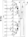
- FIG. 1B illustrates the circuitry of one embodiment of a feed network 110.
- the feed network includes a feed input/output component 150, and a power distribution network 160.
- the coupled port has a 90 degree phase difference when compared to the through port.
- a standard directional coupler can be implemented in stripline using coupled quarter wave striplines. The input signal does not undergo a phase change at the through port directly connected to the input port. The coupled port provides a signal that has a 90 degree advanced phase from the through port. The unused port is an isolated port. Standard directional couplers are used for power distribution that is unbalanced (e.g. less than -10dB for the weaker channel).
- Phase delay units are used in some channels to counteract a phase advance caused by a short feed line compared to the other channels. Phase delay units should be able to be used repeatedly with low insertion loss and a low VSWR.
- the feed input/output component 150 includes two 2-way power dividers 101 and 102 to create three output channels. With the 2-way power dividers 101 and 102, the output of both ports of the respective power divider typically have approximately the same phase.
- the input is coupled to two parallel uncoupled quarter wave transmission lines. The output of each quarter wave line is terminated with a load equal to two times the system impedance. The input and output impedances are equal. The line impedance of the system is equal to the system impedance times the square root of two ( ⁇ 2Z 0 ). Power dividers are used for power distribution that is balanced or only slightly unbalanced (e.g. 0dB to -10dB for the weaker channel).
- Power divider 101 splits an input signal into two output channels. One output from power divider 101 is coupled to the second power divider 102 and the other output is coupled directly to the center antenna element 135, such that the signal to antenna element 135 has the strongest energy distribution.
- the output channel coupled to the center antenna element 135 has a line length "L" that is pre-selected so that a feed phase that is consistent with the other feed channels is maintained.
- Power divider 102 further divides the output received from the power divider 101 into two more signal channels, one for a left side power distribution network, defined by the network providing a signal for the antenna elements to the left of the center antenna element 135, and one for a right side power distribution network, defined by the network providing a signal to the antenna elements to the right of the center antenna element 135.
- the output channel for the left side power distribution network is coupled to a power divider 103.
- the two outputs from power divider 103 are coupled to a directional coupler 111 and phase delay unit 121.
- Phase delay units such as phase delay unit 121, are used in some channels to counteract a phase advance caused by a short feed line compared to the other channels. Phase delay units should be able to be used repeatedly with low insertion loss and a low VSWR.
- Directional coupler 111 can be implemented with a conventional directional coupler.
- Conventional directional couplers include a coupled port and a through port. With directional couplers, the coupled port has a 90 degree phase difference when compared to the through port.
- a standard directional coupler can be implemented in stripline using coupled quarter wave striplines. The input signal does not undergo a phase change at the through port directly connected to the input port. The coupled port provides a signal that has a 90 degree advanced phase from the through port. The unused port is an isolated port.
- Standard directional couplers are typically used for power distribution that is unbalanced (e.g. less than -10dB for the weaker channel).
- the through port of directional coupler 111 is connected to power divider 107 and the coupled output is connected to phase delay unit 123.
- the outputs of power divider 107 feed antenna elements 130 and 131.
- the signal from the coupled port of directional coupler 111 is connected to phase delay unit 123 which adjusts the phase so that it has a phase difference of +90 degrees relative to the signal at antenna elements 130 and 131.
- the phase delay unit 123 adjusts the phase for variations in line length of the signal path to antenna elements 130 and 131, and antenna element 132.
- antenna element 132 is spatially rotated counterclockwise, in relation to the direction of signal propagation, by 90 degrees.
- Phase delay unit 121 is used to adjust the phase of the signal going to antenna elements 133 and 134 so that they are in phase with the feed signal at antenna elements 130, 131, and 132. Then the signal is split by power divider 105, which then feeds the signal to antenna elements 133 and 134.
- the circuit described above is mirrored for the right side power distribution network.
- the output channel of power divider 102 for the right side power distribution network is coupled to power divider 104.
- One of the two outputs from power divider 104 is coupled to a directional coupler 112 and the other output is coupled to phase delay unit 122.
- the through port of directional coupler 112 is connected to power divider 108 and the output of the coupled port is connected to phase delay unit 124.
- the outputs of power divider 108 feed antenna elements 139 and 140, respectively.
- the signal from the coupled port of directional coupler 112 is connected to phase delay unit 124 which adjusts the phase so that it has a phase difference of +90 degrees relative to the signal at antenna elements 139 and 140.
- antenna element 138 is spatially rotated counterclockwise, in relation to the direction of signal propagation, by 90 degrees.
- Phase delay unit 122 is used to adjust the phase of the signal going to antenna elements 136 and 137 so that they are in phase with the feed signal at antenna elements 138, 139, and 140. Then the signal output by phase delay unit 122 is split by power divider 106, which then feeds the signal to antenna elements 136 and 137.
- This feed network can be implemented in approximately 2-3 layers of stripline in a multilayered printed circuit board (PCB).
- the strong and weak signals can be isolated from each other by separating the output channels to the antenna elements in different layers.
- the output channel associated with the center antenna element is placed on one layer, while antenna elements 133, 134, 136, 137 with a lower power signal are placed on a different layer of the multilayered PCB.
- Antenna elements 130, 131, 132, 138, 139, and 140 are placed on another layer of the multilayer PCB.
- This multilayered stripline feed network can be mechanically supported such that each antenna element can be more easily soldered or connected and assembled within the support body 205 of the linear antenna array.
- multilayered stripline feed network is mechanically supported by being soldered to the support body itself.
- FIG. 2A illustrates one exemplary embodiment of an antenna array 200 using a 3-bay model.
- Each of a plurality of circular radiating elements 220 is fed through bays 210.
- the feed network is integrated into the support body 205, from where the feed signal is fed to bays 210. This allows for a compact, novel, low cost feed system for a linear antenna array.
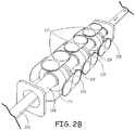
- FIG. 2B illustrates a perspective view of one embodiment of an exemplary antenna array with integrated strip line feed lines 230.
- the strip line feed lines 230 go through the center of support body 205.
- the feed lines 230 couple to an integrated feed network implemented on a multilayered stripline PCB 235 at each bay 210, upon which radiating elements 220 are mounted.
- the PCBs 235 are orthogonal relative to the plane of the stripline feed lines 230.
- the feed lines can connect to the PCBs at each bay through a variety of means for electrically coupling such feed signals.
- One such example is through the use of coaxial cables.
- the PCBs 235 can be mechanically supported within the antenna structure through a variety of means. In one embodiment, the PCBs 235 can be supported by soldering to the antenna structure itself.
- the antenna elements 220 are mounted directly on the multilayered PCBs 235, perpendicular to the plane of the PCB. This can be accomplished by mounting the antenna elements, which have slots in them, onto tabs on the PCB 235. Then, the connection can be soldered to create both an electrical and mechanical connection. Other means for mounting the antenna elements to the PCBs 235 can be implemented, such as having a slot in the PCB 235, as opposed to the antenna element 220. In yet another embodiment, the antenna elements 220 are mounted and spaced equally on four sides of the support body, all along one axis as provided by the support body.
- FIG. 3 is an exemplary flow chart illustrating one embodiment of a method of operating a linear antenna array with an integrated stripline feed network 300.
- a first signal is received by a feed input/output component and split into a second and third signal.
- the second signal is sent directly to a central antenna element, such as the central antenna element discussed above.
- further splitting of the third signal depends on the number of antenna elements needing a feed signal. If the number of antenna elements is odd, then the third signal is split into a fourth and fifth signal, which are sent to a power distribution network.
- the fourth and fifth signals can be further split into more signals, depending on the how many antenna elements are to be fed a signal.
- the signals are then output to each of a plurality of output channels.
- the phase delays introduced to the signals by the varying signal paths are adjusted within the feed network so that the phase delay output at each output channel is approximately matched.
- the feed signals are sent to the antenna elements.
- antenna elements that receive a signal with a phase delay or advancement introduced by the various feed network components are spatially rotated to adjust for the phase delay or advancement.
Landscapes
- Engineering & Computer Science (AREA)
- Computer Networks & Wireless Communication (AREA)
- Variable-Direction Aerials And Aerial Arrays (AREA)
Claims (6)
- Lineare Antennengruppe (200), umfassend:einen Trägerkörper (205) mit einer Längsachse;eine Vielzahl von Buchten (210), die sich entlang des Trägerkörpers (205) befinden, wobei jede der Buchten (210) umfasst:eine Vielzahl von Antennenelementen (130-140, 220), die um den Trägerkörper (205) herum positioniert sind; undeine mehrschichtige Leiterplatte, PCB (235), die orthogonal zur Längsachse des Trägerkörpers (205) positioniert ist; undein Streifenleitungs-Speisenetzwerk (110), das in jeder mehrschichtigen PCB (235) implementiert ist, wobei das Streifenleitungs-Speisenetzwerk mit der Vielzahl von Antennenelementen (130-140, 220) verbunden und in den Trägerkörper (205) integriert ist, wobei das Streifenleitungs-Speisenetzwerk (110) umfasst:ein Leistungsverteilungsnetz (160), das mit der Vielzahl von Antennenelementen (130-140) über eine Vielzahl von Ausgangskanälen (155) gekoppelt ist; undeine Speisesignaleingangs-/-ausgangskomponente (150), die mit dem Leistungsverteilungsnetz (160) gekoppelt ist;
wobei die Eingangs-/Ausgangskomponente (150) ein Speisesignal empfängt und das Speisesignal in eine Vielzahl von Signalen aufteilt, die durch die Ausgangskanäle (155) vom Leistungsverteilungsnetz (160) an die Vielzahl von Antennenelementen (130-140) verteilt werden;wobei das Leistungsverteilungsnetzwerk (160) eine oder mehrere Phasenverzögerungseinheiten (121-124) einschließt, die konfiguriert sind, um auf Phasenunterschiede im Speisesignal aufgrund von Variationen der Signalpfadleitungslänge jedes der Vielzahl von Antennenelementen (130-140) anzupassen;wobei die Vielzahl von Signalen, die an jeden der Ausgangskanäle (155) verteilt wird, gemäß der Signalstärke auf verschiedenen Schichten der mehrschichtigen PCB (235) getrennt wird,wobei auf den verschiedenen Schichten der mehrschichtigen PCB (235) stärkere Signale von schwächeren Signalen getrennt werden. - Lineare Antennengruppe nach Anspruch 1, wobei die Speisesignaleingangs-/- ausgangskomponente (150) konfiguriert ist, um ein direktes Speisesignal an ein zentrales Antennenelement (135) der Vielzahl von Antennenelementen bereitzustellen, wobei das Direktspeisesignal eine Speisesignal ist, das nur einmal von der Eingangs-/Ausgangskomponente aufgeteilt wurde.
- Lineare Antennengruppe nach Anspruch 1, die ferner Richtkoppler umfasst, die im Streifenleitungs-Speisenetzwerk implementiert sind, wobei mindestens eines der Antennenelemente (132, 138) räumlich gedreht wird, um auf eine jeweilige durch die Richtkoppler eingeführte Phasenverzögerung oder -voreilung anzupassen, sodass die Phase des an jedem jeweiligen Antennenelement empfangenen Speisesignals an die jeweilige Phase des an den anderen Antennenelementen empfangenen Speisesignals angepasst ist.
- Verfahren (300) zum Betreiben einer linearen Antennengruppe, wobei:
die lineare Antennengruppe umfasst:einen Trägerkörper (205) mit einer Längsachse;eine Vielzahl von Buchten (210), die sich entlang des Trägerkörpers (205) befinden, wobei jede der Buchten (210) umfasst:eine Vielzahl von Antennenelementen (130-140, 220), die um den Trägerkörper herum positioniert sind; undeine mehrschichtige Leiterplatte, PCB (235), die orthogonal zur Längsachse des Trägerkörpers positioniert ist; undein Streifenleitungs-Speisenetzwerk (110), das in jeder mehrschichtigen PCB (235) implementiert ist, wobei das Streifenleitungs-Speisenetzwerk (110) mit den Vielzahl von Antennenelementen (130-140, 220) verbunden und in den Trägerkörper (205) integriert ist, wobei das Streifenleitungs-Speisenetzwerk (110) umfasst:ein Leistungsverteilungsnetz (160), das mit der Vielzahl von Antennenelementen (130-140) über Vielzahl von Ausgangskanälen (155) gekoppelt ist; undeine Eingangs-/Ausgangskomponente (150), die mit dem Leistungsverteilungsnetz (160) gekoppelt ist;wobei das Leistungsverteilungsnetz (160) eine oder mehrere Phasenverzögerungseinheiten (121-124) einschließt;wobei das Verfahren umfasst:Empfangen (301) eines Speisesignals an der Eingangs-/Ausgangskomponente (150) des Streifenleitungs-Speisenetzwerks;Aufteilen (303) des Speisesignals in eine Vielzahl von Signalen;Verteilen (303, 305) jedes der Vielzahl von Signalen von dem Streifenleitungs-Speisenetzwerk an eine jeweilige Untergruppe der Vielzahl von Antennenelementen (130-140) durch die Ausgangskanäle (155) aus dem Leistungsverteilungsnetz (160); undAnpassen (307, 309) der Signalphase eines oder mehrerer der Vielzahl von Signalen, sodass die Signalphase des jeweiligen Signals, das an jedem der Vielzahl von Antennenelementen (130-140) empfangen wird, ungefähr gleich ist;wobei die Vielzahl von Signalen, die an jeden der Ausgangskanäle (155) verteilt werden, gemäß der Signalstärke auf verschiedenen Schichten der mehrschichtigen PCB (235) getrennt werden, wobei auf den verschiedenen Schichten der mehrschichtigen PCB stärkere Signale von schwächeren Signalen getrennt werden (235). - Verfahren nach Anspruch 4, wobei das Einstellen der Signalphase das räumliche Drehen von mindestens einem der Vielzahl von Antennenelementen der linearen Antennengruppe umfasst.
- Verfahren nach Anspruch 5, wobei das Anpassen der Signalphase das Konfigurieren einer oder mehrerer der Phasenverzögerungseinheiten umfasst, um auf Phasenunterschiede im Speisesignal anzupassen, die durch Variationen in einer jeweiligen Signalpfadleitungslänge für jedes der Vielzahl von Antennenelementen eingeführt werden.
Applications Claiming Priority (1)
| Application Number | Priority Date | Filing Date | Title |
|---|---|---|---|
| PCT/CN2013/071565 WO2014121515A1 (en) | 2013-02-08 | 2013-02-08 | Integrated stripline feed network for linear antenna array |
Publications (3)
| Publication Number | Publication Date |
|---|---|
| EP2954594A1 EP2954594A1 (de) | 2015-12-16 |
| EP2954594A4 EP2954594A4 (de) | 2016-12-07 |
| EP2954594B1 true EP2954594B1 (de) | 2022-01-12 |
Family
ID=51299218
Family Applications (1)
| Application Number | Title | Priority Date | Filing Date |
|---|---|---|---|
| EP13874608.6A Active EP2954594B1 (de) | 2013-02-08 | 2013-02-08 | Integriertes streifenleitungs-speisenetzwerk für eine lineare antennengruppe |
Country Status (4)
| Country | Link |
|---|---|
| US (1) | US9843105B2 (de) |
| EP (1) | EP2954594B1 (de) |
| CN (1) | CN104969414B (de) |
| WO (1) | WO2014121515A1 (de) |
Families Citing this family (2)
| Publication number | Priority date | Publication date | Assignee | Title |
|---|---|---|---|---|
| US9728855B2 (en) | 2014-01-14 | 2017-08-08 | Honeywell International Inc. | Broadband GNSS reference antenna |
| WO2021038965A1 (ja) * | 2019-08-27 | 2021-03-04 | 株式会社村田製作所 | アンテナモジュールおよびそれを搭載した通信装置 |
Citations (2)
| Publication number | Priority date | Publication date | Assignee | Title |
|---|---|---|---|---|
| US5285212A (en) * | 1992-09-18 | 1994-02-08 | Radiation Systems, Inc. | Self-supporting columnar antenna array |
| US5534882A (en) * | 1994-02-03 | 1996-07-09 | Hazeltine Corporation | GPS antenna systems |
Family Cites Families (85)
| Publication number | Priority date | Publication date | Assignee | Title |
|---|---|---|---|---|
| US2227563A (en) * | 1938-08-11 | 1941-01-07 | Telefunken Gmbh | Directional antenna array |
| US2539433A (en) | 1948-03-20 | 1951-01-30 | Int Standard Electric Corp | Circularly polarized antenna |
| US2757369A (en) | 1952-12-10 | 1956-07-31 | Rca Corp | Antenna system |
| US2939143A (en) | 1953-10-29 | 1960-05-31 | Sadir Carpentier | Wide band dipole antenna |
| US3413644A (en) | 1961-11-23 | 1968-11-26 | Siemens Ag | Antenna having at least two radiators fed with different phase |
| US3329959A (en) | 1962-08-13 | 1967-07-04 | Siemens Ag | Antenna comprising groups of radiators disposed in different planes |
| US3604010A (en) | 1969-01-30 | 1971-09-07 | Singer General Precision | Antenna array system for generating shaped beams for guidance during aircraft landing |
| US4021813A (en) | 1974-07-01 | 1977-05-03 | The United States Of America As Represented By The Secretary Of The Navy | Geometrically derived beam circular antenna array |
| US4090203A (en) * | 1975-09-29 | 1978-05-16 | Trw Inc. | Low sidelobe antenna system employing plural spaced feeds with amplitude control |
| US4083051A (en) | 1976-07-02 | 1978-04-04 | Rca Corporation | Circularly-polarized antenna system using tilted dipoles |
| US4160976A (en) | 1977-12-12 | 1979-07-10 | Motorola, Inc. | Broadband microstrip disc antenna |
| US4446465A (en) * | 1978-11-02 | 1984-05-01 | Harris Corporation | Low windload circularly polarized antenna |
| US4262265A (en) | 1979-03-29 | 1981-04-14 | Ford Aerospace & Communications Corporation | Side-launch transition for air stripline conductors |
| US4383226A (en) * | 1979-03-29 | 1983-05-10 | Ford Aerospace & Communications Corporation | Orthogonal launcher for dielectrically supported air stripline |
| FR2544920B1 (fr) | 1983-04-22 | 1985-06-14 | Labo Electronique Physique | Antenne plane hyperfrequences a reseau de lignes a substrat completement suspendu |
| US4590480A (en) * | 1984-08-31 | 1986-05-20 | Rca Corporation | Broadcast antenna which radiates horizontal polarization towards distant locations and circular polarization towards nearby locations |
| CA1323419C (en) | 1988-08-03 | 1993-10-19 | Emmanuel Rammos | Planar array antenna, comprising coplanar waveguide printed feed lines cooperating with apertures in a ground plane |
| US4973972A (en) | 1989-09-07 | 1990-11-27 | The United States Of America As Represented By The Administrator Of The National Aeronautics And Space Adminstration | Stripline feed for a microstrip array of patch elements with teardrop shaped probes |
| US4980692A (en) | 1989-11-29 | 1990-12-25 | Ail Systems, Inc. | Frequency independent circular array |
| FR2676310B1 (fr) | 1991-05-06 | 1993-11-05 | Alcatel Espace | Antenne a lobe forme et grand gain. |
| US5291211A (en) * | 1992-11-20 | 1994-03-01 | Tropper Matthew B | A radar antenna system with variable vertical mounting diameter |
| US5471181A (en) | 1994-03-08 | 1995-11-28 | Hughes Missile Systems Company | Interconnection between layers of striplines or microstrip through cavity backed slot |
| US5784032A (en) | 1995-11-01 | 1998-07-21 | Telecommunications Research Laboratories | Compact diversity antenna with weak back near fields |
| US5789996A (en) * | 1997-04-02 | 1998-08-04 | Harris Corporation | N-way RF power combiner/divider |
| US5861858A (en) | 1997-06-30 | 1999-01-19 | Harris Corporation | Antenna feed and support system |
| US6043722A (en) * | 1998-04-09 | 2000-03-28 | Harris Corporation | Microstrip phase shifter including a power divider and a coupled line filter |
| US5999145A (en) | 1998-06-26 | 1999-12-07 | Harris Corporation | Antenna system |
| US6621469B2 (en) | 1999-04-26 | 2003-09-16 | Andrew Corporation | Transmit/receive distributed antenna systems |
| AU4278600A (en) | 1999-04-27 | 2000-11-10 | Brian De Champlain | Single receiver wireless tracking system |
| EP1059690B1 (de) | 1999-06-07 | 2004-03-03 | Honeywell International Inc. | Antennensystem für bodengebundene Anwendungen |
| US6201510B1 (en) | 1999-07-21 | 2001-03-13 | Bae Systems Advanced Systems | Self-contained progressive-phase GPS elements and antennas |
| US6640085B1 (en) | 1999-09-01 | 2003-10-28 | Xm Satellite Radio Inc. | Electronically steerable antenna array using user-specified location data for maximum signal reception based on elevation angle |
| US6608601B1 (en) | 1999-12-21 | 2003-08-19 | Lockheed Martin Corporation | Integrated antenna radar system for mobile and transportable air defense |
| US6366185B1 (en) | 2000-01-12 | 2002-04-02 | Raytheon Company | Vertical interconnect between coaxial or GCPW circuits and airline via compressible center conductors |
| KR100442915B1 (ko) | 2000-03-10 | 2004-08-02 | 닛폰안테나 가부시키가이샤 | 크로스 다이폴 안테나 및 복합 안테나 |
| US6249261B1 (en) | 2000-03-23 | 2001-06-19 | Southwest Research Institute | Polymer, composite, direction-finding antenna |
| US6384788B2 (en) | 2000-04-07 | 2002-05-07 | Omnipless (Proprietary) Limited | Antenna with a stripline feed |
| KR20090033403A (ko) | 2000-07-10 | 2009-04-02 | 앤드류 코포레이션 | 셀룰러 안테나 |
| CN1801530A (zh) | 2000-07-10 | 2006-07-12 | 安德鲁公司 | 蜂窝天线 |
| US6480167B2 (en) * | 2001-03-08 | 2002-11-12 | Gabriel Electronics Incorporated | Flat panel array antenna |
| US6697029B2 (en) | 2001-03-20 | 2004-02-24 | Andrew Corporation | Antenna array having air dielectric stripline feed system |
| US6717555B2 (en) | 2001-03-20 | 2004-04-06 | Andrew Corporation | Antenna array |
| US6727777B2 (en) | 2001-04-16 | 2004-04-27 | Vitesse Semiconductor Corporation | Apparatus and method for angled coaxial to planar structure broadband transition |
| US20050088337A1 (en) | 2001-10-01 | 2005-04-28 | Thales North America, Inc. | Vertically stacked turnstile array |
| US20040048420A1 (en) | 2002-06-25 | 2004-03-11 | Miller Ronald Brooks | Method for embedding an air dielectric transmission line in a printed wiring board(PCB) |
| US6788272B2 (en) | 2002-09-23 | 2004-09-07 | Andrew Corp. | Feed network |
| US6885343B2 (en) | 2002-09-26 | 2005-04-26 | Andrew Corporation | Stripline parallel-series-fed proximity-coupled cavity backed patch antenna array |
| US7427962B2 (en) | 2003-06-16 | 2008-09-23 | Andrew Corporation | Base station antenna rotation mechanism |
| US6965279B2 (en) | 2003-07-18 | 2005-11-15 | Ems Technologies, Inc. | Double-sided, edge-mounted stripline signal processing modules and modular network |
| US7298332B2 (en) * | 2003-09-19 | 2007-11-20 | United States Of America As Represented By The Secretary Of The Navy | Fourteen inch X-band antenna |
| US7196674B2 (en) * | 2003-11-21 | 2007-03-27 | Andrew Corporation | Dual polarized three-sector base station antenna with variable beam tilt |
| DE102004063784A1 (de) | 2004-06-14 | 2006-07-13 | Alexandro Lisitano | Modulare Antennenanlage |
| US7119757B1 (en) | 2004-08-19 | 2006-10-10 | Bae Systems Information And Electronic Systems Integration Inc. | Dual-array two-port differential GPS antenna systems |
| US7999737B2 (en) | 2005-05-31 | 2011-08-16 | Powerwave Technologies, Inc. | Beam adjusting device |
| US7324060B2 (en) * | 2005-09-01 | 2008-01-29 | Raytheon Company | Power divider having unequal power division and antenna array feed network using such unequal power dividers |
| KR100807321B1 (ko) | 2005-12-13 | 2008-02-28 | 주식회사 케이엠더블유 | 이동통신 기지국용 가변 빔 제어 안테나 |
| DE102005063234B4 (de) | 2005-12-19 | 2007-08-30 | Fuß, Torsten, Dr.-Ing. | Tragkonstruktion zum Aufbau von Antennenmasten und dergleichen |
| CN101341630B (zh) | 2005-12-21 | 2011-11-09 | 松下电器产业株式会社 | 指向性可变天线 |
| JP4224081B2 (ja) | 2006-06-12 | 2009-02-12 | 株式会社東芝 | 円偏波アンテナ装置 |
| US7417597B1 (en) | 2007-02-20 | 2008-08-26 | Bae Systems Information And Electronic Systems Integration Inc. | GPS antenna systems and methods with vertically-steerable null for interference suppression |
| CN101051860B (zh) | 2007-05-24 | 2010-08-04 | 华为技术有限公司 | 一种馈电网络装置、天馈子系统和基站系统 |
| EP1995821B1 (de) * | 2007-05-24 | 2017-02-22 | Huawei Technologies Co., Ltd. | Speisungsvorrichtung, Antennenspeisungssubsystem und Basisstationssystem |
| CN101110499B (zh) | 2007-08-30 | 2012-12-26 | 大连海事大学 | 宽带全球局域网系统便携终端的天线装置 |
| GB0724684D0 (en) | 2007-12-18 | 2009-01-07 | Bae Systems Plc | Anntenna Feed Module |
| CN201167136Y (zh) | 2007-12-20 | 2008-12-17 | 南京捷士通无线技术有限公司 | 基站智能板状天线 |
| JP4424521B2 (ja) | 2008-03-07 | 2010-03-03 | 日本電気株式会社 | アンテナ装置、給電回路および電波送受信方法 |
| US9246224B2 (en) | 2008-03-21 | 2016-01-26 | First Rf Corporation | Broadband antenna system allowing multiple stacked collinear devices and having an integrated, co-planar balun |
| US8217850B1 (en) | 2008-08-14 | 2012-07-10 | Rockwell Collins, Inc. | Adjustable beamwidth aviation antenna with directional and omni-directional radiation modes |
| US8217839B1 (en) | 2008-09-26 | 2012-07-10 | Rockwell Collins, Inc. | Stripline antenna feed network |
| US8138986B2 (en) | 2008-12-10 | 2012-03-20 | Sensis Corporation | Dipole array with reflector and integrated electronics |
| US8049667B2 (en) | 2009-02-18 | 2011-11-01 | Bae Systems Information And Electronic Systems Integration Inc. | GPS antenna array and system for adaptively suppressing multiple interfering signals in azimuth and elevation |
| US8493278B2 (en) | 2009-03-16 | 2013-07-23 | Bae Systems Information And Electronic Systems Integration Inc. | Antennas and methods to provide adaptable omnidirectional ground nulls |
| CN102308437B (zh) | 2009-05-26 | 2013-09-11 | 华为技术有限公司 | 一种天线装置 |
| US9203161B2 (en) | 2010-05-21 | 2015-12-01 | Nec Corporation | Antenna apparatus and method of adjusting the same |
| US8610633B2 (en) | 2010-08-10 | 2013-12-17 | Victory Microwave Corporation | Dual polarized waveguide slot array and antenna |
| EP2434577A1 (de) | 2010-09-24 | 2012-03-28 | Alcatel Lucent | Antennenanordnung für die direkte Luft-Boden-Kommunikation |
| US8164532B1 (en) | 2011-01-18 | 2012-04-24 | Dockon Ag | Circular polarized compound loop antenna |
| CN102195143A (zh) | 2011-03-10 | 2011-09-21 | 东南大学 | 带倾角的宽带并馈全向天线阵 |
| KR101844427B1 (ko) | 2011-09-02 | 2018-04-03 | 삼성전자주식회사 | 무선 전력을 이용한 통신 시스템 |
| US9054403B2 (en) | 2012-06-21 | 2015-06-09 | Raytheon Company | Coaxial-to-stripline and stripline-to-stripline transitions including a shorted center via |
| CN103152015B (zh) * | 2013-01-25 | 2016-08-17 | 摩比天线技术(深圳)有限公司 | 多层pcb板结构的校准馈电网络 |
| EP2962363A4 (de) | 2013-03-01 | 2017-01-25 | Honeywell International Inc. | Erweiterung einer achsenverhältnisbandbreite für sehr niedrige anhebungen |
| US9728855B2 (en) | 2014-01-14 | 2017-08-08 | Honeywell International Inc. | Broadband GNSS reference antenna |
| US9408306B2 (en) | 2014-01-15 | 2016-08-02 | Honeywell International Inc. | Antenna array feeding structure having circuit boards connected by at least one solderable pin |
| US20150200465A1 (en) | 2014-01-16 | 2015-07-16 | Honeywell International Inc. | Equal interval multipath rejected antenna array |
-
2013
- 2013-02-08 US US13/879,300 patent/US9843105B2/en active Active
- 2013-02-08 EP EP13874608.6A patent/EP2954594B1/de active Active
- 2013-02-08 WO PCT/CN2013/071565 patent/WO2014121515A1/en not_active Ceased
- 2013-02-08 CN CN201380072511.8A patent/CN104969414B/zh active Active
Patent Citations (2)
| Publication number | Priority date | Publication date | Assignee | Title |
|---|---|---|---|---|
| US5285212A (en) * | 1992-09-18 | 1994-02-08 | Radiation Systems, Inc. | Self-supporting columnar antenna array |
| US5534882A (en) * | 1994-02-03 | 1996-07-09 | Hazeltine Corporation | GPS antenna systems |
Also Published As
| Publication number | Publication date |
|---|---|
| EP2954594A4 (de) | 2016-12-07 |
| WO2014121515A1 (en) | 2014-08-14 |
| EP2954594A1 (de) | 2015-12-16 |
| CN104969414A (zh) | 2015-10-07 |
| US9843105B2 (en) | 2017-12-12 |
| CN104969414B (zh) | 2019-02-19 |
| US20150333411A1 (en) | 2015-11-19 |
Similar Documents
| Publication | Publication Date | Title |
|---|---|---|
| US7986280B2 (en) | Multi-element broadband omni-directional antenna array | |
| US11165158B2 (en) | Integrated antenna element, antenna unit, multi-array antenna, transmission method and receiving method of same | |
| CN108063318B (zh) | 集成天线单元、多阵列天线及其传输方法及接收方法 | |
| CN113451742A (zh) | 其中集成有高性能有源天线系统(aas)的基站天线 | |
| EP3066717B1 (de) | Verfahren und systeme zur kalibrierung von lte-antennensystemen | |
| JP7067949B2 (ja) | ビバルディアンテナベースのアンテナシステム | |
| US11705614B2 (en) | Coupling device and antenna | |
| JP2018536362A (ja) | 単一平面ストリップラインフィードを有する二重偏波広帯域放射器 | |
| CN107636892A (zh) | 天线 | |
| US9728855B2 (en) | Broadband GNSS reference antenna | |
| AU2008305785B2 (en) | Antenna arrangement for a multi radiator base station antenna | |
| US11264702B1 (en) | Wideband phased array antenna mitigating effects of housing | |
| EP3916914B1 (de) | Kalibrationsleiterkarte und antennenvorrichtung damit | |
| US10700420B2 (en) | Compact multiband feed for small cell base station antennas | |
| CN104823323A (zh) | 具有4tx/4rx三频带天线布置的无线通信节点 | |
| CN116368687A (zh) | 一种天线子阵列及基站天线 | |
| US7609205B2 (en) | Electrically steerable phased array antenna system | |
| EP2954594B1 (de) | Integriertes streifenleitungs-speisenetzwerk für eine lineare antennengruppe | |
| KR20120082279A (ko) | 무도금 방사체를 포함하는 안테나 | |
| CN119153956B (zh) | 波束宽度可重构天线及基站 | |
| KR20130044250A (ko) | 무도금 방사체를 포함하는 안테나 | |
| JP6493879B2 (ja) | アンテナ装置 | |
| Afonin et al. | Antenna array of patch radiators with controlled polarization | |
| KR20150049356A (ko) | 광대역, 편파 재구성 및 광범위 다중 빔 형성을 위한 안테나 장치 | |
| KR20160082361A (ko) | 안테나용 트윈빔 제어기 및 이를 이용한 안테나 장치 |
Legal Events
| Date | Code | Title | Description |
|---|---|---|---|
| PUAI | Public reference made under article 153(3) epc to a published international application that has entered the european phase |
Free format text: ORIGINAL CODE: 0009012 |
|
| 17P | Request for examination filed |
Effective date: 20150731 |
|
| AK | Designated contracting states |
Kind code of ref document: A1 Designated state(s): AL AT BE BG CH CY CZ DE DK EE ES FI FR GB GR HR HU IE IS IT LI LT LU LV MC MK MT NL NO PL PT RO RS SE SI SK SM TR |
|
| AX | Request for extension of the european patent |
Extension state: BA ME |
|
| DAX | Request for extension of the european patent (deleted) | ||
| A4 | Supplementary search report drawn up and despatched |
Effective date: 20161107 |
|
| RIC1 | Information provided on ipc code assigned before grant |
Ipc: H01Q 1/24 20060101ALI20161101BHEP Ipc: H01Q 21/30 20060101AFI20161101BHEP |
|
| STAA | Information on the status of an ep patent application or granted ep patent |
Free format text: STATUS: EXAMINATION IS IN PROGRESS |
|
| 17Q | First examination report despatched |
Effective date: 20201211 |
|
| REG | Reference to a national code |
Ref country code: DE Ref legal event code: R079 Ref document number: 602013080698 Country of ref document: DE Free format text: PREVIOUS MAIN CLASS: H01Q0021300000 Ipc: H01Q0001240000 |
|
| GRAP | Despatch of communication of intention to grant a patent |
Free format text: ORIGINAL CODE: EPIDOSNIGR1 |
|
| STAA | Information on the status of an ep patent application or granted ep patent |
Free format text: STATUS: GRANT OF PATENT IS INTENDED |
|
| RIC1 | Information provided on ipc code assigned before grant |
Ipc: H01Q 21/20 20060101ALI20210719BHEP Ipc: H01Q 21/08 20060101ALI20210719BHEP Ipc: H01Q 21/00 20060101ALI20210719BHEP Ipc: H01Q 3/26 20060101ALI20210719BHEP Ipc: H01Q 1/24 20060101AFI20210719BHEP |
|
| INTG | Intention to grant announced |
Effective date: 20210813 |
|
| GRAS | Grant fee paid |
Free format text: ORIGINAL CODE: EPIDOSNIGR3 |
|
| GRAA | (expected) grant |
Free format text: ORIGINAL CODE: 0009210 |
|
| STAA | Information on the status of an ep patent application or granted ep patent |
Free format text: STATUS: THE PATENT HAS BEEN GRANTED |
|
| AK | Designated contracting states |
Kind code of ref document: B1 Designated state(s): AL AT BE BG CH CY CZ DE DK EE ES FI FR GB GR HR HU IE IS IT LI LT LU LV MC MK MT NL NO PL PT RO RS SE SI SK SM TR |
|
| REG | Reference to a national code |
Ref country code: GB Ref legal event code: FG4D |
|
| REG | Reference to a national code |
Ref country code: CH Ref legal event code: EP |
|
| REG | Reference to a national code |
Ref country code: DE Ref legal event code: R096 Ref document number: 602013080698 Country of ref document: DE |
|
| REG | Reference to a national code |
Ref country code: IE Ref legal event code: FG4D |
|
| REG | Reference to a national code |
Ref country code: AT Ref legal event code: REF Ref document number: 1462982 Country of ref document: AT Kind code of ref document: T Effective date: 20220215 |
|
| REG | Reference to a national code |
Ref country code: LT Ref legal event code: MG9D |
|
| REG | Reference to a national code |
Ref country code: NL Ref legal event code: MP Effective date: 20220112 |
|
| REG | Reference to a national code |
Ref country code: AT Ref legal event code: MK05 Ref document number: 1462982 Country of ref document: AT Kind code of ref document: T Effective date: 20220112 |
|
| PG25 | Lapsed in a contracting state [announced via postgrant information from national office to epo] |
Ref country code: NL Free format text: LAPSE BECAUSE OF FAILURE TO SUBMIT A TRANSLATION OF THE DESCRIPTION OR TO PAY THE FEE WITHIN THE PRESCRIBED TIME-LIMIT Effective date: 20220112 |
|
| PG25 | Lapsed in a contracting state [announced via postgrant information from national office to epo] |
Ref country code: SE Free format text: LAPSE BECAUSE OF FAILURE TO SUBMIT A TRANSLATION OF THE DESCRIPTION OR TO PAY THE FEE WITHIN THE PRESCRIBED TIME-LIMIT Effective date: 20220112 Ref country code: RS Free format text: LAPSE BECAUSE OF FAILURE TO SUBMIT A TRANSLATION OF THE DESCRIPTION OR TO PAY THE FEE WITHIN THE PRESCRIBED TIME-LIMIT Effective date: 20220112 Ref country code: PT Free format text: LAPSE BECAUSE OF FAILURE TO SUBMIT A TRANSLATION OF THE DESCRIPTION OR TO PAY THE FEE WITHIN THE PRESCRIBED TIME-LIMIT Effective date: 20220512 Ref country code: NO Free format text: LAPSE BECAUSE OF FAILURE TO SUBMIT A TRANSLATION OF THE DESCRIPTION OR TO PAY THE FEE WITHIN THE PRESCRIBED TIME-LIMIT Effective date: 20220412 Ref country code: LT Free format text: LAPSE BECAUSE OF FAILURE TO SUBMIT A TRANSLATION OF THE DESCRIPTION OR TO PAY THE FEE WITHIN THE PRESCRIBED TIME-LIMIT Effective date: 20220112 Ref country code: HR Free format text: LAPSE BECAUSE OF FAILURE TO SUBMIT A TRANSLATION OF THE DESCRIPTION OR TO PAY THE FEE WITHIN THE PRESCRIBED TIME-LIMIT Effective date: 20220112 Ref country code: ES Free format text: LAPSE BECAUSE OF FAILURE TO SUBMIT A TRANSLATION OF THE DESCRIPTION OR TO PAY THE FEE WITHIN THE PRESCRIBED TIME-LIMIT Effective date: 20220112 Ref country code: BG Free format text: LAPSE BECAUSE OF FAILURE TO SUBMIT A TRANSLATION OF THE DESCRIPTION OR TO PAY THE FEE WITHIN THE PRESCRIBED TIME-LIMIT Effective date: 20220412 |
|
| PG25 | Lapsed in a contracting state [announced via postgrant information from national office to epo] |
Ref country code: PL Free format text: LAPSE BECAUSE OF FAILURE TO SUBMIT A TRANSLATION OF THE DESCRIPTION OR TO PAY THE FEE WITHIN THE PRESCRIBED TIME-LIMIT Effective date: 20220112 Ref country code: LV Free format text: LAPSE BECAUSE OF FAILURE TO SUBMIT A TRANSLATION OF THE DESCRIPTION OR TO PAY THE FEE WITHIN THE PRESCRIBED TIME-LIMIT Effective date: 20220112 Ref country code: GR Free format text: LAPSE BECAUSE OF FAILURE TO SUBMIT A TRANSLATION OF THE DESCRIPTION OR TO PAY THE FEE WITHIN THE PRESCRIBED TIME-LIMIT Effective date: 20220413 Ref country code: FI Free format text: LAPSE BECAUSE OF FAILURE TO SUBMIT A TRANSLATION OF THE DESCRIPTION OR TO PAY THE FEE WITHIN THE PRESCRIBED TIME-LIMIT Effective date: 20220112 Ref country code: AT Free format text: LAPSE BECAUSE OF FAILURE TO SUBMIT A TRANSLATION OF THE DESCRIPTION OR TO PAY THE FEE WITHIN THE PRESCRIBED TIME-LIMIT Effective date: 20220112 |
|
| PG25 | Lapsed in a contracting state [announced via postgrant information from national office to epo] |
Ref country code: IS Free format text: LAPSE BECAUSE OF FAILURE TO SUBMIT A TRANSLATION OF THE DESCRIPTION OR TO PAY THE FEE WITHIN THE PRESCRIBED TIME-LIMIT Effective date: 20220512 |
|
| REG | Reference to a national code |
Ref country code: DE Ref legal event code: R097 Ref document number: 602013080698 Country of ref document: DE |
|
| REG | Reference to a national code |
Ref country code: CH Ref legal event code: PL |
|
| REG | Reference to a national code |
Ref country code: BE Ref legal event code: MM Effective date: 20220228 |
|
| PG25 | Lapsed in a contracting state [announced via postgrant information from national office to epo] |
Ref country code: SM Free format text: LAPSE BECAUSE OF FAILURE TO SUBMIT A TRANSLATION OF THE DESCRIPTION OR TO PAY THE FEE WITHIN THE PRESCRIBED TIME-LIMIT Effective date: 20220112 Ref country code: SK Free format text: LAPSE BECAUSE OF FAILURE TO SUBMIT A TRANSLATION OF THE DESCRIPTION OR TO PAY THE FEE WITHIN THE PRESCRIBED TIME-LIMIT Effective date: 20220112 Ref country code: RO Free format text: LAPSE BECAUSE OF FAILURE TO SUBMIT A TRANSLATION OF THE DESCRIPTION OR TO PAY THE FEE WITHIN THE PRESCRIBED TIME-LIMIT Effective date: 20220112 Ref country code: MC Free format text: LAPSE BECAUSE OF FAILURE TO SUBMIT A TRANSLATION OF THE DESCRIPTION OR TO PAY THE FEE WITHIN THE PRESCRIBED TIME-LIMIT Effective date: 20220112 Ref country code: LU Free format text: LAPSE BECAUSE OF NON-PAYMENT OF DUE FEES Effective date: 20220208 Ref country code: EE Free format text: LAPSE BECAUSE OF FAILURE TO SUBMIT A TRANSLATION OF THE DESCRIPTION OR TO PAY THE FEE WITHIN THE PRESCRIBED TIME-LIMIT Effective date: 20220112 Ref country code: DK Free format text: LAPSE BECAUSE OF FAILURE TO SUBMIT A TRANSLATION OF THE DESCRIPTION OR TO PAY THE FEE WITHIN THE PRESCRIBED TIME-LIMIT Effective date: 20220112 Ref country code: CZ Free format text: LAPSE BECAUSE OF FAILURE TO SUBMIT A TRANSLATION OF THE DESCRIPTION OR TO PAY THE FEE WITHIN THE PRESCRIBED TIME-LIMIT Effective date: 20220112 |
|
| PLBE | No opposition filed within time limit |
Free format text: ORIGINAL CODE: 0009261 |
|
| STAA | Information on the status of an ep patent application or granted ep patent |
Free format text: STATUS: NO OPPOSITION FILED WITHIN TIME LIMIT |
|
| PG25 | Lapsed in a contracting state [announced via postgrant information from national office to epo] |
Ref country code: AL Free format text: LAPSE BECAUSE OF FAILURE TO SUBMIT A TRANSLATION OF THE DESCRIPTION OR TO PAY THE FEE WITHIN THE PRESCRIBED TIME-LIMIT Effective date: 20220112 |
|
| 26N | No opposition filed |
Effective date: 20221013 |
|
| GBPC | Gb: european patent ceased through non-payment of renewal fee |
Effective date: 20220412 |
|
| PG25 | Lapsed in a contracting state [announced via postgrant information from national office to epo] |
Ref country code: LI Free format text: LAPSE BECAUSE OF NON-PAYMENT OF DUE FEES Effective date: 20220228 Ref country code: IE Free format text: LAPSE BECAUSE OF NON-PAYMENT OF DUE FEES Effective date: 20220208 Ref country code: GB Free format text: LAPSE BECAUSE OF NON-PAYMENT OF DUE FEES Effective date: 20220412 Ref country code: CH Free format text: LAPSE BECAUSE OF NON-PAYMENT OF DUE FEES Effective date: 20220228 |
|
| PG25 | Lapsed in a contracting state [announced via postgrant information from national office to epo] |
Ref country code: SI Free format text: LAPSE BECAUSE OF FAILURE TO SUBMIT A TRANSLATION OF THE DESCRIPTION OR TO PAY THE FEE WITHIN THE PRESCRIBED TIME-LIMIT Effective date: 20220112 Ref country code: BE Free format text: LAPSE BECAUSE OF NON-PAYMENT OF DUE FEES Effective date: 20220228 |
|
| P01 | Opt-out of the competence of the unified patent court (upc) registered |
Effective date: 20230525 |
|
| PG25 | Lapsed in a contracting state [announced via postgrant information from national office to epo] |
Ref country code: IT Free format text: LAPSE BECAUSE OF FAILURE TO SUBMIT A TRANSLATION OF THE DESCRIPTION OR TO PAY THE FEE WITHIN THE PRESCRIBED TIME-LIMIT Effective date: 20220112 |
|
| PG25 | Lapsed in a contracting state [announced via postgrant information from national office to epo] |
Ref country code: HU Free format text: LAPSE BECAUSE OF FAILURE TO SUBMIT A TRANSLATION OF THE DESCRIPTION OR TO PAY THE FEE WITHIN THE PRESCRIBED TIME-LIMIT; INVALID AB INITIO Effective date: 20130208 |
|
| PG25 | Lapsed in a contracting state [announced via postgrant information from national office to epo] |
Ref country code: MK Free format text: LAPSE BECAUSE OF FAILURE TO SUBMIT A TRANSLATION OF THE DESCRIPTION OR TO PAY THE FEE WITHIN THE PRESCRIBED TIME-LIMIT Effective date: 20220112 Ref country code: CY Free format text: LAPSE BECAUSE OF FAILURE TO SUBMIT A TRANSLATION OF THE DESCRIPTION OR TO PAY THE FEE WITHIN THE PRESCRIBED TIME-LIMIT Effective date: 20220112 |
|
| PG25 | Lapsed in a contracting state [announced via postgrant information from national office to epo] |
Ref country code: TR Free format text: LAPSE BECAUSE OF FAILURE TO SUBMIT A TRANSLATION OF THE DESCRIPTION OR TO PAY THE FEE WITHIN THE PRESCRIBED TIME-LIMIT Effective date: 20220112 |
|
| PG25 | Lapsed in a contracting state [announced via postgrant information from national office to epo] |
Ref country code: MT Free format text: LAPSE BECAUSE OF FAILURE TO SUBMIT A TRANSLATION OF THE DESCRIPTION OR TO PAY THE FEE WITHIN THE PRESCRIBED TIME-LIMIT Effective date: 20220112 |
|
| PGFP | Annual fee paid to national office [announced via postgrant information from national office to epo] |
Ref country code: DE Payment date: 20250226 Year of fee payment: 13 |
|
| PGFP | Annual fee paid to national office [announced via postgrant information from national office to epo] |
Ref country code: FR Payment date: 20250224 Year of fee payment: 13 |