EP2954603B1 - Dispositif d'isolation tubulaire, agencement d'alimentation à haute tension et procédé permettant de fournir un câble d'alimentation haute tension isolé - Google Patents
Dispositif d'isolation tubulaire, agencement d'alimentation à haute tension et procédé permettant de fournir un câble d'alimentation haute tension isolé Download PDFInfo
- Publication number
- EP2954603B1 EP2954603B1 EP14705490.2A EP14705490A EP2954603B1 EP 2954603 B1 EP2954603 B1 EP 2954603B1 EP 14705490 A EP14705490 A EP 14705490A EP 2954603 B1 EP2954603 B1 EP 2954603B1
- Authority
- EP
- European Patent Office
- Prior art keywords
- insulation device
- electrical
- electrical insulation
- tubular
- conductor segments
- Prior art date
- Legal status (The legal status is an assumption and is not a legal conclusion. Google has not performed a legal analysis and makes no representation as to the accuracy of the status listed.)
- Not-in-force
Links
- 238000009413 insulation Methods 0.000 title claims description 66
- 238000000034 method Methods 0.000 title claims description 29
- 239000004020 conductor Substances 0.000 claims description 184
- 238000010292 electrical insulation Methods 0.000 claims description 94
- 230000005540 biological transmission Effects 0.000 claims description 21
- 238000009434 installation Methods 0.000 claims description 19
- 238000005452 bending Methods 0.000 claims description 16
- 239000000615 nonconductor Substances 0.000 claims description 15
- 239000000203 mixture Substances 0.000 claims description 10
- 229910052751 metal Inorganic materials 0.000 claims description 9
- 239000002184 metal Substances 0.000 claims description 9
- 230000004888 barrier function Effects 0.000 claims description 5
- 238000005299 abrasion Methods 0.000 claims description 4
- 229920001940 conductive polymer Polymers 0.000 claims description 3
- 229920000642 polymer Polymers 0.000 claims description 3
- 230000001681 protective effect Effects 0.000 claims description 3
- 238000004804 winding Methods 0.000 claims description 2
- 230000008901 benefit Effects 0.000 description 10
- 239000000463 material Substances 0.000 description 7
- 238000001125 extrusion Methods 0.000 description 5
- 238000003780 insertion Methods 0.000 description 5
- 230000037431 insertion Effects 0.000 description 5
- 239000004411 aluminium Substances 0.000 description 4
- 229910052782 aluminium Inorganic materials 0.000 description 4
- XAGFODPZIPBFFR-UHFFFAOYSA-N aluminium Chemical compound [Al] XAGFODPZIPBFFR-UHFFFAOYSA-N 0.000 description 4
- 238000009826 distribution Methods 0.000 description 3
- 239000007787 solid Substances 0.000 description 3
- RYGMFSIKBFXOCR-UHFFFAOYSA-N Copper Chemical compound [Cu] RYGMFSIKBFXOCR-UHFFFAOYSA-N 0.000 description 2
- 238000010276 construction Methods 0.000 description 2
- 229910052802 copper Inorganic materials 0.000 description 2
- 239000010949 copper Substances 0.000 description 2
- 230000001419 dependent effect Effects 0.000 description 2
- 239000003989 dielectric material Substances 0.000 description 2
- 230000005684 electric field Effects 0.000 description 2
- 238000005516 engineering process Methods 0.000 description 2
- 239000011810 insulating material Substances 0.000 description 2
- 238000004519 manufacturing process Methods 0.000 description 2
- 229910000831 Steel Inorganic materials 0.000 description 1
- 230000009286 beneficial effect Effects 0.000 description 1
- 238000005352 clarification Methods 0.000 description 1
- 230000007423 decrease Effects 0.000 description 1
- 230000007547 defect Effects 0.000 description 1
- 239000012777 electrically insulating material Substances 0.000 description 1
- 230000005611 electricity Effects 0.000 description 1
- 230000007613 environmental effect Effects 0.000 description 1
- 239000012530 fluid Substances 0.000 description 1
- 239000011888 foil Substances 0.000 description 1
- 239000012774 insulation material Substances 0.000 description 1
- 239000012212 insulator Substances 0.000 description 1
- 238000005304 joining Methods 0.000 description 1
- 239000007788 liquid Substances 0.000 description 1
- 230000007774 longterm Effects 0.000 description 1
- 239000004033 plastic Substances 0.000 description 1
- 238000010248 power generation Methods 0.000 description 1
- 230000002035 prolonged effect Effects 0.000 description 1
- 238000013341 scale-up Methods 0.000 description 1
- 239000004065 semiconductor Substances 0.000 description 1
- 239000010959 steel Substances 0.000 description 1
- 229920001169 thermoplastic Polymers 0.000 description 1
- 239000004416 thermosoftening plastic Substances 0.000 description 1
- 230000000007 visual effect Effects 0.000 description 1
- 239000011800 void material Substances 0.000 description 1
- XLYOFNOQVPJJNP-UHFFFAOYSA-N water Substances O XLYOFNOQVPJJNP-UHFFFAOYSA-N 0.000 description 1
- 238000003466 welding Methods 0.000 description 1
Images

Classifications
-
- H—ELECTRICITY
- H02—GENERATION; CONVERSION OR DISTRIBUTION OF ELECTRIC POWER
- H02G—INSTALLATION OF ELECTRIC CABLES OR LINES, OR OF COMBINED OPTICAL AND ELECTRIC CABLES OR LINES
- H02G9/00—Installations of electric cables or lines in or on the ground or water
- H02G9/06—Installations of electric cables or lines in or on the ground or water in underground tubes or conduits; Tubes or conduits therefor
-
- H—ELECTRICITY
- H02—GENERATION; CONVERSION OR DISTRIBUTION OF ELECTRIC POWER
- H02G—INSTALLATION OF ELECTRIC CABLES OR LINES, OR OF COMBINED OPTICAL AND ELECTRIC CABLES OR LINES
- H02G3/00—Installations of electric cables or lines or protective tubing therefor in or on buildings, equivalent structures or vehicles
- H02G3/02—Details
- H02G3/04—Protective tubing or conduits, e.g. cable ladders or cable troughs
- H02G3/0462—Tubings, i.e. having a closed section
- H02G3/0468—Corrugated
Definitions
- the present invention relates in a first aspect to an elongated tubular electrical insulation device for a cable.
- the invention in a second aspect relates to a high voltage power cable arrangement comprising a plurality of elongated conductor segments placed alongside one another to form an inner electrical conductor of a high voltage power cable, and an elongated tubular electric insulation device arranged to house and surround the inner electrical conductor.
- a conductor segment is to be understood as a segment which is to be joined to another conductor segment at the respective end, and which together with other alongside extending conductor segments form the conductor.
- a power cable segment is to be understood as a segment which is to be joined to another cable segment at the respective end.
- the inventors of the present invention have identified that the factor that limits the scale-up of prior art power cable technology is the fact that the cross-section area of a prior art power cable cannot be increased without sacrificing overall flexibility of the power cable, which in turn results in that the length of a produced power cable segment has to be reduced, as the inflexibility of the power cable with the increased cross-section area makes it too difficult to transport, or prevents the transportation of, too long power cable segments from the production site to the site of installation.
- electric power cables may be produced by way of extrusion in a cable extrusion line, and it is desirable to produce the extruded power cable segments as long as possible to keep the number of joints on the site of installation to a minimum.
- a reduction of the length of the power cable segments results in an increase of the number of joints for joining the power cable segments in order to install the entire power transmission line. Therefore, the installation time is prolonged, and the long-term electric reliability of the power transmission or distribution system in operation decreases with an increase of the number of joints.
- US 5,043,538 describes a water impervious cable construction which includes a central electrical conductor, an overlayer of insulation material such as a plastic, a shield layer formed of a plurality of individual conductors, the shield layer being embedded in a layer of semiconducting material, a layer of overlapped moisture barrier metal foil material, and a further overlayer of insulating material.
- WO 02/27734 discloses an electrical cabling system for the transmission of power over distances.
- the cabling system includes a set of extruded aluminium tube conductors.
- US 4,298,058 describes a moisture-proofing electrical cable comprising three stranded-together insulated conductors enveloped in a rubber-elastic inner sleeve on which sits a corrugated twin tube arrangement of an inner copper tube and an outer steel tube.
- US 7,999,188-B2 discloses a cable for transporting or distributing electric energy, especially medium or high voltage electric energy, including an electrically insulating layer surrounding an electrical conductor, and a sheath surrounding the electrically insulating layer. It is disclosed that the sheath is configured to guarantee improved flexibility without impairing mechanical properties and particularly thermopressure resistance.
- EP1585204 discloses a cable arrangement for AC transmission where an installation duct houses the cables for three phases. Each phase cable has its own insulation.
- the installation duct consists of an inner screen of metal that is thick enough to ensure grounding.
- the cable is assembled at site, whereby the installation duct attains is circular shape from a planar band when rolled around the phase cables and welding the band sides together. The transportation is facilitated since the duct-to-be can be wound as a band.
- the object of the present invention is to increase the electric power transmitted by a power cable, especially a power cable for submarine installation or for installation on land, e.g. an underground cable, without any reduction of the length of the produced power cable segments with regard to limitations of the transportation of the power cable.
- a tubular electrical insulation device of the kind specified in the preamble of the independent claim related to a tubular electrical insulation device for a cable includes the specific features specified in the characterizing portion of the independent claim related to a tubular electrical insulation device for a cable.
- the tubular electric insulation device is arranged for receiving a plurality of electrical conductors segments by insertion, which tubular electrical insulation device is flexible and comprises an inner circumferential electrically conductive layer for establishing an electric contact to the electrical conductors once inserted into the tubular electrical insulation device.
- flexible means flexibility in any plane through the center line of the insulation device, i.e. the flexibility allows the insulation device to be bent.
- the insulation device according to the invention can be bent in the order of 1:6,25 to 1:25, typically in the order of 1:10 to 1:15.
- the bendability is measured as the relation between the diameter of the insulation device and the possible bending radius.
- the possible bending radius corresponds to the radius to which the insulation device can be bent without using excessive force for wounding at that radius without significant deformation, cracks or other defects.
- the insulation device thus is an entity that is separate from the conductor, and into which the conductor can be inserted to form a cable.
- the invented insulation device thereby in an advantageous way provides an essential component for obtaining a high-voltage power cable for transmitting very high electrical power.
- the invented insulation device it will be possible to attain a cable that allows much higher power than can be achieved with a conventional cable without resulting in undue short cable segments.
- For transmitting electrical power in the magnitude above 1 GW with conventional cable technique it requires either to increase the voltage to a level that creates problems of the kind discussed above or to use a plurality of cables in parallel.
- the alternative to have a "moderate" high voltage such as 320 kV and use one single cable would result in such a high conductor area that a conventional cable could not be bent to be transported on a drum. The consequence would be very short cable segments and a large number of joints. With a cable provided with an insulation device according to the invention this is avoided.
- the bending properties of a cable formed with the use of the insulation device allow transportation of the assembled cable rolled on a drum and with a segment length of some hundred meters.
- the specific construction of the insulation device also makes it possible to alternatively assemble the cable on site whereby the conductor segments and the Insulation device are transported individually to the site. Thereby the individual unassembled parts transport is lighter, and the transport weight limitation (e. g. 32 tons for road transport) is reached at much longer segment length.
- the cable segments can be increased to almost 700 meters in this example, since in that case it is the weight of the insulation device alone that has to match the weight limitation.
- the cable that can be provided with the invented insulation device in this example replaces five conventional cables. This results in that the production costs will be reduced, and so also the required space for the cable trench.
- the invented insulation device it is that flexible that it can be coiled on a drum for transportation.
- This criterion represents a well-defined degree of the flexibility with reference to the maximum conventional size of standard cable transportation drums. This degree of flexibility assures that the beneficial effects of the invented insulation device are taken advantage of with regards to essential aspects.
- the inner circumferential electrically conductive layer is dimensionally stable such that its ring-shaped cross-section is maintained when coiled on the drum for transportation.
- the electrical insulation device is that flexible that its bending radius is in a range of 4 to 20 times the outer diameter of the tubular electrical insulation device.
- range is 4 to 10 times.
- the specified range for the bending radius in particular the narrow range, represents a bending property that is optimized for the purpose of the present invention in consideration on one hand the transport aspect and on the other hand other practical aspects such as the stability. It is to be understood that the term bending radius in this context means the radius to which the insulation device can be bent without using excessive force or injuring the insulation device.
- the inner circumferential electrically conductive layer of the tubular electrical insulation device is a corrugated tube or a strip wound hose.
- the tubular electrical insulation device is produced by extrusion. Typically it is thus seamless in a longitudinal direction defined by the overall tubular shape of the tubular electrical insulation device.
- the electrical insulation device comprises at least one circumferential electrical insulator located outside of and surrounding the electrically conductive inner layer, and a circumferential electrically conductive outer layer located outside of and surrounding the at least one circumferential electrical insulator.
- the at least one circumferential electrical insulator may comprise one or a plurality of circumferential electrical insulators. At least one of the electrically conductive inner and outer layers may be semiconductive. Outside the outer conductive layer other circumferential layers may be added e.g. as environmental protection.
- each of the electrically conductive inner and outer layers is made of a metal or a metal composition, or made of an electrically conductive polymer or polymer composition.
- the electrically conductive inner and outer layers are arranged to form a protective barrier protecting the at least one circumferential electric insulator from moisture and mechanical abrasion.
- This embodiment is suitable for the inventive concept provided by the present invention, where the power cable is assembled on site, as the electrical insulator of the electrical insulation device is protected both at the inside and at the outside during the transportation of the electrical insulation device and the plurality of elongated electrical conductor segments unassembled. Further, during the assembly of the electrical insulation device and the plurality of elongated electrical conductor segments, the electrical insulator of the electrical insulation device is also protected from any mechanical abrasion effected by the plurality of elongated electrical conductor segments.
- a flexible and efficient cable insulation system is provided.
- At least one of the electrically conductive inner and outer layers is covered on the outside and/or on the inside with a semiconductive material.
- both of the layers are covered.
- a semiconductive material in this context is meant a semiconductive material following the definition that it has low electrical conductivity but on the other hand conducts electricity better than an insulating material.
- the electrical insulation capacity is such that it can be used in a high voltage power cable.
- the invention is particularly of interest for ultra-high voltage such as voltage levels at 320 kV and above.
- the thickness of the insulation layer is larger than 30 mm.
- the layer is at least 60 mm thick, which is suitable for ultra-high voltage applications.
- the inner layer has an internal diameter of at least 80 mm, preferably at least 120 mm.
- the large internal diameter allows to house conductor segments of a total conductive cross sectional area little less than 5 000 mm 2 at a fill-ratio of 90%. Often when applying the invention, however, the requirement of the conductive cross sectional area will be much higher and the fill-ratio will be lower. For example for a 3 GW-transmission the conductive cross-sectional area may be 21 000 mm 2 and the fill-ratio 50%. This requires the internal diameter to be around 230 mm. A preferred range of the internal diameter is 80 to 400 mm, preferably 120 to 250 mm.
- the internal diameter may vary in the longitudinal direction, e. g. when the inner layer is a corrugated tube. In that case the term "internal diameter" relates to the minimum appearing internal diameter.
- fill-ratio is defined further below.
- a high voltage power cable arrangement of the kind specified in the preamble of the independent claim related to a high voltage cable arrangement includes the specific features specified in the characterizing portion of the independent claim related to a high voltage cable arrangement.
- the cable arrangement thus is provided with a tubular electric insulation device according to the present invention, in particular according to any of the preferred embodiments thereof.
- the invented high voltage power arrangement has advantages of similar kind as those of the invented insulation device and the preferred embodiments thereof and which have been described above.
- the plurality of conductor segments may be bundled together, e.g. by tape, wire or the like in order to simplify insertion of the conductor segments into the insulation device.
- At least one conductor segment of the conductor is in electrical contact with at least another along-side extending conductor segment of the conductor.
- the invention may be applied also when the cable contains conductor segments that are insulated from each other, the advantages of the invention are of primary interest when the conductor segments are in electrical contact with each other to form a common conductor, in particular when all conductor segments are in electrical contact with each other.
- the individual electrical conductor segments are that flexible that they can be coiled on a drum.
- the individual electrical conductor segments are that flexible that their bending radius is such that the conductor segments fit the bendability of the insulation device according the embodiment above specifying the wider range for the bendability thereof.
- the bending radius of the individual electrical conductor segments is such that the conductor segments fit the bendability of the insulation device according the embodiment above specifying the narrower range for the bendability thereof.
- the embodiments mentioned next above have advantages of similar kind as the embodiments of the invented tubular electrical insulation device that relate to the bending properties thereof.
- the clarifications regarding what is meant by flexible and by bending radius is presented above in connection with the insulation device, and these are relevant also to the cable.
- the bending radius of the conductor segments will be in a range of about 5 to 25 times, and 5 to 12,5 times, respectively, of the outer diameter of the tubular electrical insulation device.
- the plurality of elongated electrical conductor segments is at least partly loosely arranged in relation to the insulation device such that electrical conductor segments can move relative to the insulation device when the high voltage power cable arrangement is bent.
- loosely arranged is meant that the conductor segments are not fixed or attached to the inner periphery of the insulation device as is the case with a conventional extruded cable. This, however, does not exclude that the conductor segments are in contact with the inner periphery of the insulation device.
- the conductor parts may be loosely arranged along the entire length but may alternatively be attached to the inner periphery of the insulation device at certain spots along the cable.
- the number of along-side extending conductor segments of the conductor is at least four.
- the conductive cross sectional area of the conductor is at least 3 000 mm 2 , preferably at least 5 000 mm 2 .
- This is the sum of the conductive cross sectional areas of the conductor segments.
- the benefits of the present invention is larger, the larger the power is and thus the larger the conductive cross sectional area is for a given voltage. This is why it is preferred to apply the invention for cross sections above the specified.
- the advantages are most pertinent when the conductive cross sectional area is above 10 000 mm 2 and in particular above 20 000 mm 2 .
- the invention may be applied for conductive cross sectional areas up to twice and even five times that figure.
- the internal cross sectional area of the insulation device is the sum of the conductive cross sectional area of the conductor and an excess cross sectional area, which excess cross sectional area is at least 10 % of said internal cross sectional area of the insulation device.
- the excess cross sectional area may completely be formed by a void space, but may also include non-conductive components housed within the electrically insulating device such as insulation around one or more of the conductor segments.
- the excess cross sectional area is in the range of 20 to 50%.
- the fill-ratio is the ratio between the cross sectional area of the conductor and the internal cross sectional area of the insulation device.
- a fill-ratio of e.g. 30% thus means an excess cross sectional area of 70%.
- the internal cross sectional area of the insulation device is related to the minimum appearing diameter.
- the above-mentioned object of the present invention is according to the third aspect of the invention attained by providing a method for providing an insulated high voltage power cable, the method comprises the steps of providing a plurality of elongated electrical conductor segments; providing an elongated tubular electrical insulation device; transporting the plurality of elongated electrical conductor segments and the electrical insulation device unassembled to a site of installation; and assembling the plurality of elongated electrical conductor segments and the electrical insulation device on site to form an electrical conductor of the plurality of elongated electrical conductor segments and to form an insulated high voltage power cable of the electrical conductor and the tubular electrical insulation device, wherein the step of assembling the plurality of elongated electrical conductor segments and the electrical insulation device comprises inserting the plurality of elongated electrical conductor segments into the prefabricated tubular electrical insulation device.
- the site of installation may be the actual location where the cable is to be installed as well as an intermediate assembly site where the cable after the specified transport is prepared for the installation.
- the inventors of the present invention have identified that the individual elongated electrical conductor segments and the cable insulation system when being unassembled are more flexible for transportation in relation to an assembled insulated high voltage power cable segment including an inner electrical conductor and a cable insulation system.
- the electrical conductor segments and the electrical insulation device can be transported separately, thus, a potential weight limitation for transport (e.g. on a truck) can be avoided.
- longer lengths of the individual elongated electrical conductor segments and the tubular electrical insulation device can be transported compared to an assembled high voltage power cable segment of corresponding dimensions.
- the transportation of an insulated high voltage power cable or cable segment is facilitated, especially the transportation of a high voltage power cable or cable segment providing both a large cross-section area of the inner electrical conductor and a long continuous cable segment length.
- an increase in the electric power transmitted by, or the current carrying capability of, a power cable, especially a power cable for installation on land, e.g. an underground cable, or subsea is attained by the increase in cross-section area of the inner electrical conductor, with only little impairing the flexibility of the high voltage power cable during transportation.
- the increase of the cross-section area of the inner electrical conductor attained by the method according to the present invention requires only small reduction of the cable segment length for the transportation and thus few additional joints.
- power cable segments having longer lengths can be transported in an efficient manner by means of the method of the present invention.
- the number of joints can be kept to a minimum, the installation is made more efficient, the installation costs are reduced, and the reliability of the power transmission or distribution system in operation can be increased.
- the step of assembling the plurality of elongated electrical conductor segments and the electrical insulation device comprises placing the plurality of elongated electrical conductor segments alongside one another and in electrical contact to one another to form the electrical conductor.
- the method is characterized by placing the plurality of elongated electrical conductor segments alongside one another and in electrical contact to one another to assemble the electrical conductor before being inserted into the tubular electrical insulation device.
- the method is characterized by placing the plurality of elongated electrical conductor segments alongside one another and in electrical contact to one another to assemble the electrical conductor inside the tubular electrical insulation device.
- the step of transporting the plurality of elongated electrical conductor segments and the electrical insulation device comprises individually winding the plurality of elongated electrical conductor segments and the electrical insulation device unassembled onto at least one drum or roll.
- an efficient transportation is provided.
- the plurality of elongated electrical conductor segments and the electrical insulation device may also be transported unassembled in other ways, e.g. by being coiled without said drum or roll.
- the elongated tubular electrical insulation device is a tubular electrical insulation device according to the present invention, in particular according to any of the preferred embodiments thereof.
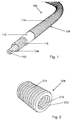
- Fig. 1 schematically shows aspects of an embodiment of the high voltage power cable arrangement according to the present invention.
- the high voltage power cable arrangement comprises a plurality of elongated electrical conductor segments 102 arranged to be placed alongside one another and in electrical contact to one another to form an inner electrical conductor 104 of a high voltage power cable 106.
- the high voltage power cable 106 may be a high voltage direct current (HVDC) cable or a high voltage alternating current (HVAC) cable.
- the high voltage power cable arrangement comprises an elongated tubular electrical insulation device 108 arranged to house and surround the inner electrical conductor 104 formed from the electrical conductor segments 102.
- Fig. 2 shows a section of another embodiment of the elongated tubular electrical insulation device 208, which may essentially correspond to the electrical insulation device 108 of Fig. 1 . It is to be understood that the electrical insulation device 208 of Fig. 2 has a longer length than shown in Fig. 2 .
- the plurality of elongated electrical conductor segments 102 is insertable into the tubular electrical insulation device 108; 208.
- the plurality of elongated electrical conductor segments 102 and the electrical insulation device 108; 208 are arranged to be transported unassembled to a site of installation.
- the plurality of elongated electrical conductor segments 102 and the electrical insulation device 108; 208 are arranged to be assembled on site to form the inner electrical conductor 104 of the plurality of elongated electrical conductor segments 102 and to form an insulated high voltage power cable 106 of the inner electrical conductor 104 and the electrical insulation device 108; 208.
- the site of installation is the location where the high voltage power cable 106 is to be installed, e.g. on land, such as in the ground.
- the individual electrical conductor segments 102 and the electrical insulation device 108; 208 are flexible for transportation.
- Each electrical insulation device 108; 208 may comprise a circumferential electrically conductive inner layer 110; 210 arranged to house and surround the plurality of elongated electrical conductor segments 102, at least one circumferential electrical insulator 112; 212 located outside of and surrounding the electrically conductive inner layer 110; 210, and a circumferential electrically conductive outer layer 114; 214 located outside of and surrounding the at least one circumferential electrical insulator 112; 212.
- the inner layer 110; 210 may be corrugated.
- the outer layer 114; 214 may be corrugated.
- Each of the electrically conductive inner and outer layers 110, 114; 210, 214 may be covered on the outside and/or on the inside with a semiconductive material.
- the at least one circumferential electrical insulator 112; 212 may comprise at least one solid or fluid insulator, e.g. an electrically insulating liquid or an electrically insulating gas or gas mixture, e.g. SF 6 , or any other suitable insulating gas or gas mixture.
- the at least one circumferential electrical insulator 112; 212 may comprise at least one circumferential electrically insulating layer, e.g. one or a plurality of solid layers, e.g. made of an electrically insulating material, e.g. a dielectric material.
- the at least one circumferential electrical insulator 112; 212 may comprise mixtures of the above-mentioned alternatives, e.g.
- the electrical insulation device 108; 208 may comprise one or more additional circumferential layers arranged to surround the plurality of elongated electrical conductor segments, e.g. at least one circumferential semiconductive layer.
- Each of the electrically conductive inner and outer layers may be made of a metal or a metal composition, or any other electrically conductive material, e.g. an electrically conductive polymer or polymer composition, e.g. an electrically conductive thermoplastic.
- the electrically conductive inner and outer layers 110, 114; 210, 214 are arranged to form a protective barrier that protects the at least one circumferential electrical insulator 112; 212 from moisture and mechanical abrasion.
- the electrical insulation device 108; 208 is arranged to electrically insulate the inner electrical conductor 104 housed therein from the exterior.
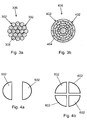
- each electrical conductor segment 302; 402 may comprise a single electrically conductive strand 304 or a single electrically conductive profile wire 404, or a plurality of electrically conductive strands 304 or a plurality of electrically conductive profile wires 404.
- Figs. 3a-b schematically illustrate the electrical conductor segments 302; 402 when they have been placed alongside one another and in electrical contact to one another and assembled to an electrical conductor 306; 406.
- the strands 304 or wires 404 may be made of copper or aluminium, or any other suitable electrically conductive material or material composition.
- Figs. 4a-b schematically illustrate further embodiments of the plurality of elongated electrical conductor segments.
- the plurality of elongated electrical conductor segments 502 comprises two segments 502 arranged to be placed alongside one another and in electrical contact to one another to form an inner electrical conductor of a high voltage power cable.
- the plurality of elongated electrical conductor segments 602 comprises four segments 602 arranged to be placed alongside one another and in electrical contact to one another to form an inner electrical conductor of a high voltage power cable.
- the plurality of elongated electrical conductor segments may, e.g., be held together by a tape having a longitudinal extension. However, when placed inside the electrical insulation device 108; 208, the electrical conductor segments may be held together without such tape.
- the plurality of elongated electrical conductor segments may be arranged together alongside one another in an axial direction and in electrical contact to one another without mechanically compacting the electrical conductor segments together in a radial direction.
- the electrical conductor segments may be mechanically compacted in a radial direction when the inner electrical conductor is formed.
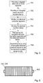
- the embodiment of the method comprises the steps of providing a plurality of elongated electrical conductor segments, at step 701, and providing an elongated tubular electrical insulation device, at step 702.
- the electrical conductor segments 102; 302; 402; 502; 602 and the electrical insulation device 108; 208 may correspond to the embodiments disclosed above.
- the plurality of elongated electrical conductor segments may be individually wound in an unassembled state onto at least one drum or roll, at step 703.
- the electrical insulation device 108; 208 may be individually wound unassembled onto at least one drum or roll 802, at step 704 (see Fig. 6 ).
- Fig. 6 schematically illustrates an insulation device 108; 208 wound onto a drum or roll 802 in a plurality of layers both in the radial direction and in the longitudinal direction of the drum or roll 802. It is to be understood that each electrical conductor segment 102; 302; 402; 502; 602 may be wound in a corresponding way.
- the plurality of elongated electrical conductor segments and the electrical insulation device are transported unassembled to a site of installation, at step 705.
- the plurality of elongated electrical conductor segments and the electrical insulation device may be transported unassembled wound onto drums or rolls 802 as mentioned above.
- the plurality of elongated electrical conductor segments and the electrical insulation device may be transported unassembled without being wound onto drums or rolls 802.
- the embodiment of the method comprises the step of assembling the plurality of elongated electrical conductor segments and the electrical insulation device on site to form an electrical conductor of the plurality of elongated electrical conductor segments and to form an insulated high voltage power cable of the electrical conductor and the tubular electrical insulation device, at step 706.
- the step of assembling the plurality of elongated electrical conductor segments and the electrical insulation device comprises inserting the plurality of elongated electrical conductor segments into the tubular electrical insulation device.
- the step of assembling the plurality of elongated electrical conductor segments and the electrical insulation device may comprise placing the plurality of elongated electrical conductor segments alongside one another and in electrical contact to one another to form the electrical conductor.
- the plurality of elongated electrical conductor segments may be placed alongside one another and in electrical contact to one another to assemble the electrical conductor before being inserted into the tubular electrical insulation device.
- the plurality of elongated electrical conductor segments may be placed alongside one another and in electrical contact to one another to assemble the electrical conductor inside the tubular electrical insulation device.
- the inner metal layer of the electrical insulation device may be a corrugated profile as depicted in fig. 2
- the inner layer may be a strip wound metallic hose.
- Fig.7 illustrates an example of such a hose 810.
- a further example of the invented insulated high voltage power cable is illustrated in fig. 8 .
- the power transmitted by the cable is 3 GW.
- the outer metallic layer 914 is the armouring, screen and moisture barrier, but is for clarity reasons depicted simplified. So is also the inner layer 910 of the insulation device which in reality is corrugated or strip wound. In between is the insulation layer 912, which is applied by triple extrusion using the inner layer 910. as the basement for the extrusion.
- the conductor device 904 housed within the insulation device 908 consist in this example of ten conductor sections 902, each being an aluminium strand with a diameter of 52mm.
- the internal diameter of the inner layer is 231 mm and the external diameter of the insulation device is 307 mm.
- the fill-factor is about 50 %.
- the conductive area of the conductor device 904 is about 21 000 mm 2 , and with a current density of 0, 45 A/mm 2 the current will be 9,4 kA. Transmitting at a voltage of 320 kV thereby results in 3 GW.
- the cable When the cable is assembled at the factory the cable will be transported in segments of 309 m. It is wound onto a drum at a bending ratio of 1:10,4.
- the weight of the aluminium strands is 58 kg/m and the weight of the insulation device is 47 kg/m.
- the complete segment thus has a weight of about 32 t.
- the segments can be longer due to the stronger bending ratio, and the segment length in this case is 681 m. Thereby the number of joints is reduced to less than the half.
- the conductor segments all have equal diameter, but the cable may alternative comprise conductor segments of different diameter.
- High Voltage for AC may be about 1-1.5 kV and above. However, for HVDC applications and systems, High Voltage may be about 72 kV and above, e.g. 320 kV, 500 kV, 800 kV or 1000 kV, and above. HVDC power transmission has an advantage over HVAC power transmission for distances over 100km because of voltage drop and electric stability limits between sending and receiving line ends.
Landscapes
- Insulated Conductors (AREA)
- Cable Accessories (AREA)
Claims (15)
- Dispositif tubulaire d'isolation électrique (108, 208) pour former un agencement de câble de transmission d'alimentation haute tension une fois qu'une pluralité de segments conducteurs électriques (104 ; 306 ; 406) sont insérés dans le dispositif tubulaire d'isolation électrique (108 ; 208 ; 908), caractérisé en ce que :le dispositif tubulaire d'isolation électrique (108, 208) est flexible, flexible en termes d'aptitude au cintrage, et comprend une couche circonférentielle intérieure électriquement conductrice (110, 210, 810) pour établir un contact électrique avec les conducteurs électriques (104 ; 306 ; 406) une fois insérés dans le dispositif tubulaire d'isolation électrique (108, 208, 908), et où le dispositif tubulaire d'isolation électrique (108, 208) est conçu pour isoler électriquement les conducteurs électriques (104 ; 306 ; 406) de l'extérieur du dispositif tubulaire d'isolation électrique (108, 208) une fois insérés dans le dispositif tubulaire d'isolation électrique (108, 208, 908).
- Dispositif tubulaire d'isolation électrique (108, 208) selon la revendication 1, caractérisé en ce que le dispositif d'isolation électrique (108 ; 208) est flexible au point qu'il peut être enroulé sur un tambour pour être transporté, et en ce que la couche circonférentielle intérieure électriquement conductrice (110, 210) est dimensionnellement stable de sorte que sa section transversale en forme d'anneau est préservée lorsqu'elle est enroulée sur le tambour pour le transport.
- Dispositif tubulaire d'isolation électrique (108, 208) selon la revendication 1 ou la revendication 2, caractérisé en ce que le dispositif d'isolation électrique (108 ; 208) est flexible au point que son rayon de courbure est compris entre 4 et 20 fois le diamètre externe du dispositif tubulaire d'isolation électrique (108, 208), de préférence entre 4 et 10 fois ce diamètre.
- Dispositif tubulaire d'isolation électrique (108, 208) selon l'une quelconque des revendications 1 à 3, caractérisé en ce que la couche circonférentielle intérieure électriquement conductrice (110, 210) est un tube annelé ou un tuyau formé d'une bande enroulée.
- Dispositif tubulaire d'isolation électrique (108, 208) selon la revendication 1, caractérisé en ce que le dispositif tubulaire d'isolation électrique (108 ; 208) comprend au moins un isolant électrique circonférentiel (112 ; 212) situé à l'extérieur et entourant la couche intérieure électriquement conductrice (110, 210), et une couche circonférentielle extérieure électriquement conductrice (114 ; 214) située à l'extérieur et entourant l'au moins un isolant électrique circonférentiel (112 ; 212), et en ce que chacune des couches intérieure et extérieure électriquement conductrices (110, 114 ; 210, 214) est constituée d'un métal ou d'une composition métallique, ou est constituée d'un polymère électriquement conducteur ou d'une composition de polymère.
- Dispositif tubulaire d'isolation électrique (108, 208) selon la revendication 5, caractérisé en ce que les couches intérieure et extérieure électriquement conductrices (110, 114 ; 210, 214) sont agencées pour former une barrière protectrice protégeant l'au moins un isolant électrique circonférentiel (112 ; 212) de l'humidité et de l'abrasion mécanique.
- Dispositif tubulaire d'isolation électrique selon l'une quelconque des revendications 1 à 6, caractérisé en ce que la couche interne a un diamètre interne d' au moins 80 mm, de préférence d'au moins 120 mm.
- Agencement de câble de transmission d'alimentation haute tension comprenant :une pluralité de segments allongés de conducteurs électriques (102 ; 302 ; 402 ; 502 ; 602) placés côte à côte et de manière à former un conducteur électrique interne (104 ; 306 ; 406) d'un câble d'alimentation haute tension, etun dispositif tubulaire d'isolation électrique (108 ; 208) agencé pour loger et entourer le conducteur électrique interne, caractérisé en ce que
le dispositif tubulaire d'isolation électrique (108, 208) est conforme à l'une quelconque des revendications 1 à 7. - Agencement de câble de transmission d'alimentation haute tension selon la revendication 8, caractérisé en ce qu'au moins un segment conducteur (102, 302, 402, 502, 602, 902) du conducteur (104, 306, 406, 904) est en contact électrique avec au moins un autre segment conducteur s'étendant à côté (102, 302, 402, 502, 602, 902) du conducteur (104, 306, 406, 904).
- Agencement de câble de transmission d'alimentation haute tension selon l'une quelconque des revendications 8 et 9, caractérisé en ce que la pluralité de segments allongés de conducteurs électriques (102 ; 302 ; 402 ; 502 ; 602) est au moins partiellement agencée de manière lâche par rapport au dispositif d'isolation (108, 208, 908) de manière à ce que des segments de conducteurs électriques (102 ; 302 ; 402 ; 502 ; 602) puissent bouger par rapport au dispositif d'isolation (108, 208, 908) lorsque l'agencement de câble d'alimentation haute tension est cintré.
- Agencement de câble de transmission d'alimentation haute tension selon l'une quelconque des revendications 8 à 10, caractérisé en ce que le nombre de segments allongés côte à côte de conducteurs électriques (102, 302, 402, 502, 602, 902) du conducteur (104, 306, 406, 904) est au moins quatre, et en ce que la surface de la section transversale conductrice du conducteur (104, 306, 406, 904) est au moins 3000 mm2.
- Agencement de câble de transmission d'alimentation haute tension selon l'une quelconque des revendications 8 à 11, caractérisé en ce que la section transversale interne du dispositif d'isolation (108, 208, 908) est la somme de la section transversale conductrice du conducteur (104, 306, 406, 904) et d'une section transversale excédentaire, laquelle section transversale excédentaire représente au moins 10 % de la section transversale interne du dispositif d'isolation.
- Procédé pour fournir un câble de transmission d'alimentation haute tension isolé flexible, le procédé comprenant les étapes suivantes :pourvoir (701) une pluralité de segments allongés électriquement conducteurs flexibles ;pourvoir (702) un dispositif tubulaire d'isolation électrique allongé flexible selon l'une quelconque des revendications 1 à 7 ;transporter (705) la pluralité de segments allongés électriquement conducteurs flexibles et le dispositif d'isolation électrique, non assemblés, jusqu'à un site d'installation ; etassembler (706) la pluralité de segments allongés électriquement conducteurs et le dispositif d'isolation électrique sur site pour former un conducteur électrique de la pluralité de segments allongés de conducteurs électriques et pour former un câble d'alimentation haute tension isolé flexible du conducteur électrique et du dispositif d'isolation électrique, où l'étape d'assemblage de la pluralité de segments allongés de conducteurs électriques et du dispositif d'isolation électrique comprend d'insérer la pluralité des segments allongés de conducteurs électriques dans le dispositif tubulaire d'isolation électrique.
- Procédé selon la revendication 13, caractérisé en ce que l'étape d'assemblage (706) de la pluralité de segments allongés de conducteurs électriques et du dispositif d'isolation électrique comprend de placer la pluralité de segments allongés de conducteurs électriques côte à côte les uns des autres et en contact électrique les uns des autres pour former le conducteur électrique.
- Procédé selon l'une quelconque des revendications 13 et 14, caractérisé en ce que l'étape de transport (705) de la pluralité de segments allongés de conducteurs électriques et du dispositif d'isolation électrique comprend d'enrouler individuellement (703 ; 704) la pluralité de segments allongés de conducteurs électriques et le dispositif d'isolation électrique, non assemblés, sur au moins un tambour ou une bobine (802).
Priority Applications (1)
| Application Number | Priority Date | Filing Date | Title |
|---|---|---|---|
| EP14705490.2A EP2954603B1 (fr) | 2013-02-07 | 2014-02-07 | Dispositif d'isolation tubulaire, agencement d'alimentation à haute tension et procédé permettant de fournir un câble d'alimentation haute tension isolé |
Applications Claiming Priority (3)
| Application Number | Priority Date | Filing Date | Title |
|---|---|---|---|
| EP2013052366 | 2013-02-07 | ||
| EP14705490.2A EP2954603B1 (fr) | 2013-02-07 | 2014-02-07 | Dispositif d'isolation tubulaire, agencement d'alimentation à haute tension et procédé permettant de fournir un câble d'alimentation haute tension isolé |
| PCT/EP2014/052390 WO2014122244A1 (fr) | 2013-02-07 | 2014-02-07 | Dispositif d'isolation tubulaire, agencement d'alimentation à haute tension et procédé permettant de fournir un câble d'alimentation haute tension isolé |
Publications (2)
| Publication Number | Publication Date |
|---|---|
| EP2954603A1 EP2954603A1 (fr) | 2015-12-16 |
| EP2954603B1 true EP2954603B1 (fr) | 2016-04-20 |
Family
ID=54427507
Family Applications (1)
| Application Number | Title | Priority Date | Filing Date |
|---|---|---|---|
| EP14705490.2A Not-in-force EP2954603B1 (fr) | 2013-02-07 | 2014-02-07 | Dispositif d'isolation tubulaire, agencement d'alimentation à haute tension et procédé permettant de fournir un câble d'alimentation haute tension isolé |
Country Status (1)
| Country | Link |
|---|---|
| EP (1) | EP2954603B1 (fr) |
-
2014
- 2014-02-07 EP EP14705490.2A patent/EP2954603B1/fr not_active Not-in-force
Also Published As
| Publication number | Publication date |
|---|---|
| EP2954603A1 (fr) | 2015-12-16 |
Similar Documents
| Publication | Publication Date | Title |
|---|---|---|
| JP5674961B2 (ja) | 高圧電気ケーブル | |
| AU2020409844B2 (en) | AC submarine power cable with reduced losses | |
| US20140124263A1 (en) | Joint for hv cables insulated with impregnated paper or paper-polypropylene laminate (ppl) | |
| US20220130575A1 (en) | Power cable joint system | |
| CN107078492B (zh) | 用于高压输电线的管状电绝缘体 | |
| US6917272B2 (en) | Electric device | |
| EP3172808B1 (fr) | Ligne de transport d'électricité haute tension (ht) | |
| US20150357804A1 (en) | A tubular insulation device, a high voltage power arrangement and a method for providing an insulated high voltage power cable | |
| US20210249151A1 (en) | Electric power cable | |
| EP2954603B1 (fr) | Dispositif d'isolation tubulaire, agencement d'alimentation à haute tension et procédé permettant de fournir un câble d'alimentation haute tension isolé | |
| US3792191A (en) | Enclosure for conductor of electrical transmission system | |
| Nikolov et al. | Overview on contemporary constructions of high voltage cables | |
| KR102776987B1 (ko) | 전력 케이블용 종단 접속함 | |
| US20250087385A1 (en) | Submarine Power Cable System With Reduced Losses | |
| CN212230120U (zh) | 一种低烟无卤环保电缆 | |
| CN210692184U (zh) | 三相铜管电缆 | |
| JP2002157923A (ja) | 電気絶縁母線及びその製造方法 | |
| Endersby et al. | Polypropylene paper laminate oil filled cable and accessories for EHV application | |
| JP2024108134A (ja) | 3芯から3つの単芯へのhvまたはehv海底電力ケーブルシステム | |
| KR20240149025A (ko) | 기중 종단접속체(eb-a) 및 이를 구비하는 전력케이블 종단접속 시스템 | |
| BOUCHEKARA | Transmission and Distribution of Electrical Power | |
| KR20000007312A (ko) | 가교 폴리에틸렌 절연 동시스 전력 케이블 | |
| JPH0250684B2 (fr) |
Legal Events
| Date | Code | Title | Description |
|---|---|---|---|
| PUAI | Public reference made under article 153(3) epc to a published international application that has entered the european phase |
Free format text: ORIGINAL CODE: 0009012 |
|
| 17P | Request for examination filed |
Effective date: 20150907 |
|
| AK | Designated contracting states |
Kind code of ref document: A1 Designated state(s): AL AT BE BG CH CY CZ DE DK EE ES FI FR GB GR HR HU IE IS IT LI LT LU LV MC MK MT NL NO PL PT RO RS SE SI SK SM TR |
|
| AX | Request for extension of the european patent |
Extension state: BA ME |
|
| GRAP | Despatch of communication of intention to grant a patent |
Free format text: ORIGINAL CODE: EPIDOSNIGR1 |
|
| DAX | Request for extension of the european patent (deleted) | ||
| INTG | Intention to grant announced |
Effective date: 20160105 |
|
| GRAS | Grant fee paid |
Free format text: ORIGINAL CODE: EPIDOSNIGR3 |
|
| GRAA | (expected) grant |
Free format text: ORIGINAL CODE: 0009210 |
|
| AK | Designated contracting states |
Kind code of ref document: B1 Designated state(s): AL AT BE BG CH CY CZ DE DK EE ES FI FR GB GR HR HU IE IS IT LI LT LU LV MC MK MT NL NO PL PT RO RS SE SI SK SM TR |
|
| REG | Reference to a national code |
Ref country code: GB Ref legal event code: FG4D |
|
| REG | Reference to a national code |
Ref country code: CH Ref legal event code: EP |
|
| REG | Reference to a national code |
Ref country code: AT Ref legal event code: REF Ref document number: 793375 Country of ref document: AT Kind code of ref document: T Effective date: 20160515 |
|
| REG | Reference to a national code |
Ref country code: IE Ref legal event code: FG4D |
|
| REG | Reference to a national code |
Ref country code: DE Ref legal event code: R096 Ref document number: 602014001587 Country of ref document: DE |
|
| REG | Reference to a national code |
Ref country code: NL Ref legal event code: FP |
|
| REG | Reference to a national code |
Ref country code: LT Ref legal event code: MG4D |
|
| REG | Reference to a national code |
Ref country code: AT Ref legal event code: MK05 Ref document number: 793375 Country of ref document: AT Kind code of ref document: T Effective date: 20160420 |
|
| PG25 | Lapsed in a contracting state [announced via postgrant information from national office to epo] |
Ref country code: LT Free format text: LAPSE BECAUSE OF FAILURE TO SUBMIT A TRANSLATION OF THE DESCRIPTION OR TO PAY THE FEE WITHIN THE PRESCRIBED TIME-LIMIT Effective date: 20160420 Ref country code: FI Free format text: LAPSE BECAUSE OF FAILURE TO SUBMIT A TRANSLATION OF THE DESCRIPTION OR TO PAY THE FEE WITHIN THE PRESCRIBED TIME-LIMIT Effective date: 20160420 Ref country code: NO Free format text: LAPSE BECAUSE OF FAILURE TO SUBMIT A TRANSLATION OF THE DESCRIPTION OR TO PAY THE FEE WITHIN THE PRESCRIBED TIME-LIMIT Effective date: 20160720 Ref country code: PL Free format text: LAPSE BECAUSE OF FAILURE TO SUBMIT A TRANSLATION OF THE DESCRIPTION OR TO PAY THE FEE WITHIN THE PRESCRIBED TIME-LIMIT Effective date: 20160420 |
|
| PG25 | Lapsed in a contracting state [announced via postgrant information from national office to epo] |
Ref country code: HR Free format text: LAPSE BECAUSE OF FAILURE TO SUBMIT A TRANSLATION OF THE DESCRIPTION OR TO PAY THE FEE WITHIN THE PRESCRIBED TIME-LIMIT Effective date: 20160420 Ref country code: PT Free format text: LAPSE BECAUSE OF FAILURE TO SUBMIT A TRANSLATION OF THE DESCRIPTION OR TO PAY THE FEE WITHIN THE PRESCRIBED TIME-LIMIT Effective date: 20160822 Ref country code: GR Free format text: LAPSE BECAUSE OF FAILURE TO SUBMIT A TRANSLATION OF THE DESCRIPTION OR TO PAY THE FEE WITHIN THE PRESCRIBED TIME-LIMIT Effective date: 20160721 Ref country code: LV Free format text: LAPSE BECAUSE OF FAILURE TO SUBMIT A TRANSLATION OF THE DESCRIPTION OR TO PAY THE FEE WITHIN THE PRESCRIBED TIME-LIMIT Effective date: 20160420 Ref country code: SE Free format text: LAPSE BECAUSE OF FAILURE TO SUBMIT A TRANSLATION OF THE DESCRIPTION OR TO PAY THE FEE WITHIN THE PRESCRIBED TIME-LIMIT Effective date: 20160420 Ref country code: RS Free format text: LAPSE BECAUSE OF FAILURE TO SUBMIT A TRANSLATION OF THE DESCRIPTION OR TO PAY THE FEE WITHIN THE PRESCRIBED TIME-LIMIT Effective date: 20160420 Ref country code: AT Free format text: LAPSE BECAUSE OF FAILURE TO SUBMIT A TRANSLATION OF THE DESCRIPTION OR TO PAY THE FEE WITHIN THE PRESCRIBED TIME-LIMIT Effective date: 20160420 Ref country code: ES Free format text: LAPSE BECAUSE OF FAILURE TO SUBMIT A TRANSLATION OF THE DESCRIPTION OR TO PAY THE FEE WITHIN THE PRESCRIBED TIME-LIMIT Effective date: 20160420 |
|
| REG | Reference to a national code |
Ref country code: DE Ref legal event code: R097 Ref document number: 602014001587 Country of ref document: DE |
|
| PG25 | Lapsed in a contracting state [announced via postgrant information from national office to epo] |
Ref country code: CZ Free format text: LAPSE BECAUSE OF FAILURE TO SUBMIT A TRANSLATION OF THE DESCRIPTION OR TO PAY THE FEE WITHIN THE PRESCRIBED TIME-LIMIT Effective date: 20160420 Ref country code: DK Free format text: LAPSE BECAUSE OF FAILURE TO SUBMIT A TRANSLATION OF THE DESCRIPTION OR TO PAY THE FEE WITHIN THE PRESCRIBED TIME-LIMIT Effective date: 20160420 Ref country code: EE Free format text: LAPSE BECAUSE OF FAILURE TO SUBMIT A TRANSLATION OF THE DESCRIPTION OR TO PAY THE FEE WITHIN THE PRESCRIBED TIME-LIMIT Effective date: 20160420 Ref country code: SK Free format text: LAPSE BECAUSE OF FAILURE TO SUBMIT A TRANSLATION OF THE DESCRIPTION OR TO PAY THE FEE WITHIN THE PRESCRIBED TIME-LIMIT Effective date: 20160420 Ref country code: RO Free format text: LAPSE BECAUSE OF FAILURE TO SUBMIT A TRANSLATION OF THE DESCRIPTION OR TO PAY THE FEE WITHIN THE PRESCRIBED TIME-LIMIT Effective date: 20160420 |
|
| REG | Reference to a national code |
Ref country code: FR Ref legal event code: PLFP Year of fee payment: 4 |
|
| PLBE | No opposition filed within time limit |
Free format text: ORIGINAL CODE: 0009261 |
|
| STAA | Information on the status of an ep patent application or granted ep patent |
Free format text: STATUS: NO OPPOSITION FILED WITHIN TIME LIMIT |
|
| PG25 | Lapsed in a contracting state [announced via postgrant information from national office to epo] |
Ref country code: SM Free format text: LAPSE BECAUSE OF FAILURE TO SUBMIT A TRANSLATION OF THE DESCRIPTION OR TO PAY THE FEE WITHIN THE PRESCRIBED TIME-LIMIT Effective date: 20160420 |
|
| 26N | No opposition filed |
Effective date: 20170123 |
|
| REG | Reference to a national code |
Ref country code: DE Ref legal event code: R081 Ref document number: 602014001587 Country of ref document: DE Owner name: ABB SCHWEIZ AG, CH Free format text: FORMER OWNER: ABB TECHNOLOGY LTD., ZUERICH, CH |
|
| PG25 | Lapsed in a contracting state [announced via postgrant information from national office to epo] |
Ref country code: SI Free format text: LAPSE BECAUSE OF FAILURE TO SUBMIT A TRANSLATION OF THE DESCRIPTION OR TO PAY THE FEE WITHIN THE PRESCRIBED TIME-LIMIT Effective date: 20160420 |
|
| PG25 | Lapsed in a contracting state [announced via postgrant information from national office to epo] |
Ref country code: MC Free format text: LAPSE BECAUSE OF FAILURE TO SUBMIT A TRANSLATION OF THE DESCRIPTION OR TO PAY THE FEE WITHIN THE PRESCRIBED TIME-LIMIT Effective date: 20160420 |
|
| REG | Reference to a national code |
Ref country code: IE Ref legal event code: MM4A |
|
| PG25 | Lapsed in a contracting state [announced via postgrant information from national office to epo] |
Ref country code: LU Free format text: LAPSE BECAUSE OF NON-PAYMENT OF DUE FEES Effective date: 20170207 |
|
| REG | Reference to a national code |
Ref country code: CH Ref legal event code: PFUS Owner name: ABB SCHWEIZ AG, CH Free format text: FORMER OWNER: ABB TECHNOLOGY LTD., CH |
|
| REG | Reference to a national code |
Ref country code: FR Ref legal event code: PLFP Year of fee payment: 5 |
|
| PG25 | Lapsed in a contracting state [announced via postgrant information from national office to epo] |
Ref country code: IE Free format text: LAPSE BECAUSE OF NON-PAYMENT OF DUE FEES Effective date: 20170207 |
|
| REG | Reference to a national code |
Ref country code: NL Ref legal event code: PD Owner name: ABB SCHWEIZ AG; CH Free format text: DETAILS ASSIGNMENT: CHANGE OF OWNER(S), MERGE; FORMER OWNER NAME: ABB TECHNOLOGY LTD. Effective date: 20180115 Ref country code: BE Ref legal event code: FP Effective date: 20160714 Ref country code: BE Ref legal event code: PD Owner name: ABB SCHWEIZ AG; CH Free format text: DETAILS ASSIGNMENT: CHANGE OF OWNER(S), CESSION; FORMER OWNER NAME: ABB TECHNOLOGY LTD. Effective date: 20180112 |
|
| REG | Reference to a national code |
Ref country code: GB Ref legal event code: 732E Free format text: REGISTERED BETWEEN 20180426 AND 20180502 |
|
| REG | Reference to a national code |
Ref country code: DE Ref legal event code: R084 Ref document number: 602014001587 Country of ref document: DE |
|
| PG25 | Lapsed in a contracting state [announced via postgrant information from national office to epo] |
Ref country code: MT Free format text: LAPSE BECAUSE OF NON-PAYMENT OF DUE FEES Effective date: 20170207 |
|
| REG | Reference to a national code |
Ref country code: FR Ref legal event code: TP Owner name: ABB SCHWEIZ AG, CH Effective date: 20180912 |
|
| PG25 | Lapsed in a contracting state [announced via postgrant information from national office to epo] |
Ref country code: AL Free format text: LAPSE BECAUSE OF FAILURE TO SUBMIT A TRANSLATION OF THE DESCRIPTION OR TO PAY THE FEE WITHIN THE PRESCRIBED TIME-LIMIT Effective date: 20160420 |
|
| PGFP | Annual fee paid to national office [announced via postgrant information from national office to epo] |
Ref country code: NL Payment date: 20190218 Year of fee payment: 6 |
|
| PGFP | Annual fee paid to national office [announced via postgrant information from national office to epo] |
Ref country code: DE Payment date: 20190219 Year of fee payment: 6 Ref country code: CH Payment date: 20190218 Year of fee payment: 6 Ref country code: GB Payment date: 20190218 Year of fee payment: 6 Ref country code: IT Payment date: 20190225 Year of fee payment: 6 |
|
| PGFP | Annual fee paid to national office [announced via postgrant information from national office to epo] |
Ref country code: FR Payment date: 20190220 Year of fee payment: 6 Ref country code: BE Payment date: 20190218 Year of fee payment: 6 |
|
| PG25 | Lapsed in a contracting state [announced via postgrant information from national office to epo] |
Ref country code: HU Free format text: LAPSE BECAUSE OF FAILURE TO SUBMIT A TRANSLATION OF THE DESCRIPTION OR TO PAY THE FEE WITHIN THE PRESCRIBED TIME-LIMIT; INVALID AB INITIO Effective date: 20140207 |
|
| PG25 | Lapsed in a contracting state [announced via postgrant information from national office to epo] |
Ref country code: BG Free format text: LAPSE BECAUSE OF FAILURE TO SUBMIT A TRANSLATION OF THE DESCRIPTION OR TO PAY THE FEE WITHIN THE PRESCRIBED TIME-LIMIT Effective date: 20160420 |
|
| PG25 | Lapsed in a contracting state [announced via postgrant information from national office to epo] |
Ref country code: CY Free format text: LAPSE BECAUSE OF FAILURE TO SUBMIT A TRANSLATION OF THE DESCRIPTION OR TO PAY THE FEE WITHIN THE PRESCRIBED TIME-LIMIT Effective date: 20160420 |
|
| PG25 | Lapsed in a contracting state [announced via postgrant information from national office to epo] |
Ref country code: MK Free format text: LAPSE BECAUSE OF FAILURE TO SUBMIT A TRANSLATION OF THE DESCRIPTION OR TO PAY THE FEE WITHIN THE PRESCRIBED TIME-LIMIT Effective date: 20160420 |
|
| PG25 | Lapsed in a contracting state [announced via postgrant information from national office to epo] |
Ref country code: TR Free format text: LAPSE BECAUSE OF FAILURE TO SUBMIT A TRANSLATION OF THE DESCRIPTION OR TO PAY THE FEE WITHIN THE PRESCRIBED TIME-LIMIT Effective date: 20160420 |
|
| PG25 | Lapsed in a contracting state [announced via postgrant information from national office to epo] |
Ref country code: IS Free format text: LAPSE BECAUSE OF FAILURE TO SUBMIT A TRANSLATION OF THE DESCRIPTION OR TO PAY THE FEE WITHIN THE PRESCRIBED TIME-LIMIT Effective date: 20160820 |
|
| REG | Reference to a national code |
Ref country code: DE Ref legal event code: R119 Ref document number: 602014001587 Country of ref document: DE |
|
| REG | Reference to a national code |
Ref country code: CH Ref legal event code: PL |
|
| REG | Reference to a national code |
Ref country code: NL Ref legal event code: MM Effective date: 20200301 |
|
| GBPC | Gb: european patent ceased through non-payment of renewal fee |
Effective date: 20200207 |
|
| REG | Reference to a national code |
Ref country code: BE Ref legal event code: MM Effective date: 20200229 |
|
| PG25 | Lapsed in a contracting state [announced via postgrant information from national office to epo] |
Ref country code: CH Free format text: LAPSE BECAUSE OF NON-PAYMENT OF DUE FEES Effective date: 20200229 Ref country code: LI Free format text: LAPSE BECAUSE OF NON-PAYMENT OF DUE FEES Effective date: 20200229 |
|
| PG25 | Lapsed in a contracting state [announced via postgrant information from national office to epo] |
Ref country code: NL Free format text: LAPSE BECAUSE OF NON-PAYMENT OF DUE FEES Effective date: 20200301 |
|
| PG25 | Lapsed in a contracting state [announced via postgrant information from national office to epo] |
Ref country code: GB Free format text: LAPSE BECAUSE OF NON-PAYMENT OF DUE FEES Effective date: 20200207 Ref country code: FR Free format text: LAPSE BECAUSE OF NON-PAYMENT OF DUE FEES Effective date: 20200229 Ref country code: DE Free format text: LAPSE BECAUSE OF NON-PAYMENT OF DUE FEES Effective date: 20200901 |
|
| PG25 | Lapsed in a contracting state [announced via postgrant information from national office to epo] |
Ref country code: BE Free format text: LAPSE BECAUSE OF NON-PAYMENT OF DUE FEES Effective date: 20200229 |
|
| PG25 | Lapsed in a contracting state [announced via postgrant information from national office to epo] |
Ref country code: IT Free format text: LAPSE BECAUSE OF NON-PAYMENT OF DUE FEES Effective date: 20200207 |