EP2954796B1 - Bolzenmechanismus für einen schuh sowie schuh - Google Patents
Bolzenmechanismus für einen schuh sowie schuh Download PDFInfo
- Publication number
- EP2954796B1 EP2954796B1 EP15170796.5A EP15170796A EP2954796B1 EP 2954796 B1 EP2954796 B1 EP 2954796B1 EP 15170796 A EP15170796 A EP 15170796A EP 2954796 B1 EP2954796 B1 EP 2954796B1
- Authority
- EP
- European Patent Office
- Prior art keywords
- shoe
- stud
- shoe sole
- operation mode
- studs
- Prior art date
- Legal status (The legal status is an assumption and is not a legal conclusion. Google has not performed a legal analysis and makes no representation as to the accuracy of the status listed.)
- Active
Links
Images



Classifications
-
- A—HUMAN NECESSITIES
- A43—FOOTWEAR
- A43B—CHARACTERISTIC FEATURES OF FOOTWEAR; PARTS OF FOOTWEAR
- A43B13/00—Soles; Sole-and-heel integral units
- A43B13/14—Soles; Sole-and-heel integral units characterised by the constructive form
- A43B13/22—Soles made slip-preventing or wear-resisting, e.g. by impregnation or spreading a wear-resisting layer
- A43B13/24—Soles made slip-preventing or wear-resisting, e.g. by impregnation or spreading a wear-resisting layer by use of insertions
- A43B13/26—Soles made slip-preventing or wear-resisting, e.g. by impregnation or spreading a wear-resisting layer by use of insertions projecting beyond the sole surface
-
- A—HUMAN NECESSITIES
- A43—FOOTWEAR
- A43B—CHARACTERISTIC FEATURES OF FOOTWEAR; PARTS OF FOOTWEAR
- A43B3/00—Footwear characterised by the shape or the use
- A43B3/24—Collapsible or convertible
- A43B3/246—Collapsible or convertible characterised by the sole
-
- A—HUMAN NECESSITIES
- A43—FOOTWEAR
- A43B—CHARACTERISTIC FEATURES OF FOOTWEAR; PARTS OF FOOTWEAR
- A43B3/00—Footwear characterised by the shape or the use
- A43B3/34—Footwear characterised by the shape or the use with electrical or electronic arrangements
-
- A—HUMAN NECESSITIES
- A43—FOOTWEAR
- A43B—CHARACTERISTIC FEATURES OF FOOTWEAR; PARTS OF FOOTWEAR
- A43B3/00—Footwear characterised by the shape or the use
- A43B3/34—Footwear characterised by the shape or the use with electrical or electronic arrangements
- A43B3/38—Footwear characterised by the shape or the use with electrical or electronic arrangements with power sources
- A43B3/40—Batteries
-
- A—HUMAN NECESSITIES
- A43—FOOTWEAR
- A43B—CHARACTERISTIC FEATURES OF FOOTWEAR; PARTS OF FOOTWEAR
- A43B3/00—Footwear characterised by the shape or the use
- A43B3/34—Footwear characterised by the shape or the use with electrical or electronic arrangements
- A43B3/44—Footwear characterised by the shape or the use with electrical or electronic arrangements with sensors, e.g. for detecting contact or position
-
- A—HUMAN NECESSITIES
- A43—FOOTWEAR
- A43C—FASTENINGS OR ATTACHMENTS OF FOOTWEAR; LACES IN GENERAL
- A43C15/00—Non-skid devices or attachments
- A43C15/005—Nails, pins
-
- A—HUMAN NECESSITIES
- A43—FOOTWEAR
- A43C—FASTENINGS OR ATTACHMENTS OF FOOTWEAR; LACES IN GENERAL
- A43C15/00—Non-skid devices or attachments
- A43C15/06—Ice-gripping devices or attachments, e.g. ice-spurs, ice-cleats, ice-creepers, crampons; Climbing devices or attachments, e.g. mountain climbing irons
- A43C15/061—Ice-gripping devices or attachments, e.g. ice-cleats, ice-creepers
-
- A—HUMAN NECESSITIES
- A43—FOOTWEAR
- A43C—FASTENINGS OR ATTACHMENTS OF FOOTWEAR; LACES IN GENERAL
- A43C15/00—Non-skid devices or attachments
- A43C15/12—Small releasable non-slip straps
-
- A—HUMAN NECESSITIES
- A43—FOOTWEAR
- A43C—FASTENINGS OR ATTACHMENTS OF FOOTWEAR; LACES IN GENERAL
- A43C15/00—Non-skid devices or attachments
- A43C15/14—Non-skid devices or attachments with outwardly-movable spikes
-
- A—HUMAN NECESSITIES
- A43—FOOTWEAR
- A43C—FASTENINGS OR ATTACHMENTS OF FOOTWEAR; LACES IN GENERAL
- A43C15/00—Non-skid devices or attachments
- A43C15/16—Studs or cleats for football or like boots
-
- A—HUMAN NECESSITIES
- A43—FOOTWEAR
- A43C—FASTENINGS OR ATTACHMENTS OF FOOTWEAR; LACES IN GENERAL
- A43C15/00—Non-skid devices or attachments
- A43C15/16—Studs or cleats for football or like boots
- A43C15/161—Studs or cleats for football or like boots characterised by the attachment to the sole
Definitions
- the present invention relates to shoes, and more specifically to improving the gripping ability of shoes with a friction increasing movable sole construction, and to controlling said movable sole construction into the actual operation mode and out of it.
- a typical and known solution has been to use separate anti-slip grips fixed on the shoe soles, and such anti-slip grip is typically formed e.g. by fixing a plurality of metal studs or other metal parts to an anti-slip grip frame made of plastic or fabric.
- Another known solution has been to equip the shoe sole with an appropriate embossing and/or material already in connection with the manufacture in order to achieve a sufficiently strong friction e.g. between the shoe sole and the ice.
- More advanced prior art solutions are different stud solutions located in the shoe soles, in which the studs can be moved into the shoe sole and out from the shoe sole with a hydraulic solution which is mechanical or based on a manual pump.
- the studs are brought up by turning an actuator, i.e. a small lever, mounted in the ankle part of the shoe.
- the connection between the lever and the studs has been implemented in the publication through a flexible guide bar, worm gear, threaded part, flexible threaded bogie and gears (see Fig. 9).
- Patent publication US 6,125,556 discloses a golf shoe, in which there is a liquid reservoir in the heel part of the shoe, from which reservoir liquid and thus pressure can be guided by a hydraulic pump to the other end of the movable stud, so that the stud comes out and remains in the protruding position also when the force caused by walking is exerted thereon.
- a separate control valve it is controlled that the liquid is moving in the valve to only one direction, when the operation mode of the stud assembly is changed, and that the liquid is not moving, when it is desired that the studs remain in their places either outside or inside the shoe sole.
- Patent publication US 4,873,774 discloses a stud arrangement to be located on shoe soles, in which arrangement the studs are fixed in the piston inside the cylinders located on the shoe sole. Air or liquid can be pumped into the cylinder through a manually operated pump or hose, the other end of which can be fixed at the height of the belt of the user. By opening the valve which is in connection with the pump the studs can be brought to roll back into the shoe sole.
- Utility model FI 6772 discloses an anti-slip grip solution, in which the movement of the stud out and in from the shoe sole can be controlled pneumatically or hydraulically by pressure cylinders. Said control can be carried out by a remote control.
- Patent FI 123280 discloses a control method for a stud arrangement, in which method the transfer between the passive and active position of the studs is controlled with a magnetically activating reversing switch and with an activation magnet of the reversing switch.
- the position of the studs is changed, when the reversing switch and the activation magnet of the opposite shoe are placed physically sufficiently close to one another.
- the switches and magnets can be located in the shoes so that in order to change the position of the studs the user should move the tip of the shoe next to the heel of the other shoe, slightly crossed compared to the normal walking technique. This way the change of the mode of the studs can be easily made without the need of manual operation, and on the other hand with this positioning the possibility of the unintended activation of the studs during walking or running is eliminated.
- US 2007/0261271 A1 discloses an active shoe cleat system.
- the problem of the known technique is that in order to change the position of the studs even in the most advanced version (the latest disclosed) of the above-mentioned shoe solutions the foot needs to be moved to the side slightly over the line of the other shoe. This causes, particularly with elderly people and people with physical constraints, the fact that the balance cannot necessarily be kept, and there will be a risk of falling and getting injured. Since the purpose of the actual studs is to improve safety by increasing the gripping ability, the controlling of the operation of the studs by the user must not cause a safety risk to the users. The stud arrangement and its control mechanism thus need an improvement, which does not develop a risk of losing balance for the user of the shoes.
- the present invention discloses a method for controlling the operation of the transfer mechanism of at least one stud located in the shoe sole, with which transfer mechanism the at least one stud located in the shoe sole can be transferred between the active operation mode and the passive operation mode.
- the characteristic feature of the method is that the transfer mechanism for at least one stud from the active operation mode to the passive operation mode and vice versa is activated when the signal measured by the acceleration sensor located in the shoe exceeds the set acceleration threshold value, and further when said signal indicates that the position of the shoe is at least partly upright for at least the set first time window.
- control logic located in the shoe is arranged to activate the transfer mechanism of the studs when the signal measured by the acceleration sensor exceeds the set threshold value twice in a row during the set second time window as a result of the double kicking movement performed by the user of the shoe.
- the power source located in the shoe acts as a power supply of the transfer mechanism, which power source supplies the electric motor as a function of the control signal given by the control logic, in which function the control signal is activated on the basis of the measurement information of the acceleration sensor.
- said acceleration threshold value and said length of the first and the second time window can be set user-specifically or user group-specifically or as a constant value.
- the acceleration threshold value is 0,3 g, i.e. 2.943 m/s 2 . This is only an example, and the value can be varied according to the target of application also to another desired value.
- the inventive idea of the present invention also comprises a shoe sole, to which sole at least one movable stud has been arranged, and the shoe sole comprises a transfer mechanism of the studs, which enables the transfer of at least one stud between the active operation mode and the passive operation mode.
- a characteristic feature of the shoe sole is that it comprises at least one acceleration sensor having a connection to the transfer mechanism, which is arranged to change the operation mode of the studs, when the signal measured by the acceleration sensor exceeds the set acceleration threshold value, and further when said signal indicates that the position of the shoe is at least partly upright for at least the set first time window.
- the shoe comprises a control logic, which is arranged to activate the transfer mechanism of the studs, when the signal measured by the acceleration sensor exceeds the set threshold value twice in a row during the set second time window as a result of the double kicking movement performed by the user of the shoe.
- each stud is arranged in a separate stud module.
- the shoe sole comprises a heel unit, which can be located to the heel of the shoe, where the heel unit comprises at least one stud module.
- the heel unit comprises a power source and an electric motor for generating rotational energy, and a control logic, which is arranged to receive the measurement information from the acceleration sensor, and to give a control signal to the electric motor on the basis of the measurement information.
- the power supply to the electric motor located in the heel unit comes from outside the shoe sole.
- the power source and the electric motor are located outside the sole in the upper part of the shoe, and there are connections from the power source and electric motor to at least one stud module.
- the transfer mechanism comprises at least one power transmission element for transmitting the signal given by the control logic from the electric motor to a movement of at least one stud between the active and the passive operation mode.
- the power transmission element is a gear, bevel gear, transmission plate, a toothed bar or a push bar threaded on its outer surface.
- At least two stud modules are located in the shoe sole so as to contact the at least one toothed or push bar acting as a part of the transfer mechanism, in which contact each stud module comprises a gear and stud control means in said contact for bringing the stud to a longitudinal movement triggered by the control signal.
- control logic has been arranged on a circuit board in the heel unit and the circuit board comprises a memory and a clock for saving and using the necessary parameters.
- the heel unit comprises a battery, wherein the battery can be replaced by a longitudinal movement from the first end of the battery compartment.
- the heel unit comprises a battery, wherein the battery can be charged through the charging line connector located in the other end of the battery compartment.
- the shoe comprises a battery, wherein the battery is located inside the upper of the leg part of the shoe and wherein the electric connection from the battery to the electric motor located in the shoe heel is arranged with cables inside the upper of the shoe.
- the present invention discloses a shoe sole, which has an outstanding gripping ability and which is safe and easily changeable regarding its different operation modes, and a shoe equipped with a corresponding sole as well as a method for changing the friction properties of the shoe sole by the user of the shoe.
- the shoe sole of the invention comprises at least one stud. Naturally, there can also be several studs and they can be located in the heel, ball part of the shoe or, where necessary, also elsewhere in the shoe sole.
- the location of the studs is not especially limited in the invention, but in practise it is most reasonable and safest to locate the studs in the shoe at least in the shoe heel, but, where necessary, also in the ball part of the shoe.
- the studs can be each located to a so-called stud module, which is discussed later in connection with the figures.
- the shoe further comprises an arrangement and equipment for controlling the positioning, i.e. the protrusion, of the studs in relation to the level of the shoe sole, i.e. whether the studs are protruding from the profile of the shoe sole to bring extra grip or "rolled in” inside the profile of the shoe sole.
- the shoe needs some kind of intelligence, i.e. a control unit, such as a controller, to manage the activation or deactivation of the movement of the studs.
- the equipment requires mechanical connections for transmitting the information given by the control unit to all studs.
- the transmissions can be realized by a mechanical bar arrangement, which is described below.
- a shoe sole In a shoe sole according to the invention at least two substantially different operation modes are needed, when observing the positioning of the studs.
- the active operation mode is needed in the shoe for walking in slippery outdoor conditions (ice, hard ridge of snow on road) or indoor spaces (e.g. a slippery floor), whereby the embossing of the shoe sole is not solely sufficient to offer a sufficient gripping ability (friction) between the shoe and the walking surface in normal walking.
- the studs are partly protruded from the surface of the shoe sole so that the other end of the studs clearly contacts the walking surface when the user is walking.
- the active operation mode corresponds thus regarding the positioning of the studs a traditional prior art situation, in which the user has placed separate anti-slip grips having a button or Velcro strap fastening to his or her shoe soles.
- the other end of the stud extends, when observing the cross-sectional profile of the sole, e.g. 2-3 mm below the rest of the profile of the shoe sole and the stud module.
- the studs must have a good contact with the walking surface, but on the other hand due to the simplicity and user friendliness of the equipment it is not good for a stud to form too high a platform when transferring from the normal use to the operation mode of the studs.
- the studs can be locked into said protruding position, so that the weight of the user does not make the studs to move back into the shoe sole during walking or running.
- the passive operation mode in its part, is associated with conditions, in which there is no need for extra grip between the walking surface and the shoe and wherein the shoe externally seen functions like a traditional shoe without studs.
- a passive operation mode the studs have been guided inside the profile of the shoe sole so that they are not in physical contact with the walking surface when the user is walking or running with the shoes.
- the inventive idea of the present invention comprises in addition to the shoe sole also the entire shoe, in which a shoe sole according to the invention can be manufactured instead of an ordinary shoe sole and connected to the frame of the normal shoe.
- a separate sole structure can be separately placed and fixed "on" the sole or around the edges of the sole as an additional part, which is according to the present invention.
- the user can separately fasten his or her foot or shoe with appropriate fastening solutions, such as straps, Velcro straps, or the sole edge of the additional part can be e.g. of flexible rubber or of a similar shapable material formed in a curved form.
- the inventive idea of the present invention further comprises a method and the parts necessary for its implementation for controlling the operation of the stud arrangement in the shoe sole structure, which arrangement substantially increases gripping ability, as a response to the impulse given by the user.
- the operation mode of the shoe sole can be changed easily, intelligently and also in a user-safe manner.
- the inventive idea of the invention comprises a heel unit to be fixed to the heel part of the shoe sole or to be integrally manufactured to the shoe heel in connection with the manufacture of the shoe sole.
- At least one stud module can be located in the heel unit.
- two, three or four stud modules are located in one heel unit.
- the stud modules and through them also the actual studs can be located in a preferred embodiment in a symmetrical arrangement to the shoe sole in order to guarantee the wearing comfort, balance and safety experienced by the user.
- FIG 1 a shows an example of the shoe heel unit 10 according to the invention, which heel unit is literally located in the heel part of the shoe either as a separate part or integrally in connection with the manufacture of the entire shoe.
- the heel unit 10 comprises in this example two stud modules 101, 102, but there can also be another desired number of stud modules.
- the number of stud modules is in practise limited by the volume they require in the shoe heel and on the other hand the complexity of the structure, and also the manufacturing costs increase with the increase of the number of the stud modules.
- the heel unit 10 comprises a casing 103, which appears more clearly in Figure 1b.
- Figure 1b shows the heel unit from the opposite side compared to Figure 1 a.
- a battery 104 or another power source which is a cylinder-like part in the Figure, is located in the edge of the heel unit 10 (preferably to the side of the heel closest to the middle part of the shoe).
- the casing 103 is formed in its one edge so that the cylinder-like battery 104 fits well in the casing.
- the first plug 105a is on the left side of the battery 104 seen from Figure1b and the second plug 105b is on the right side.
- the battery 104 can, where necessary, be moved in the direction of its longitudinal axis in relation to the casing 103, so that it can be removed from its place and taken out from the heel unit 10 through the opened plug 105a. If the battery 104 is e.g.
- a spring (not shown in the Figure) can be mounted near (e.g. to the end of the second plug 105b) the second end of the battery 104, due to the power of which spring the cylinder-like battery bounces slightly outwards, when the first plug 105a is opened.
- the battery can thus be replaced by moving the battery out from the battery compartment with a longitudinal movement, either by tilting the shoe heel or with a spring solution.
- two contact spots (contact electrodes) have been mounted to the wall of the battery compartment, which contact spots are arranged to form a contact with the terminals of the battery which is placed in its place.
- the battery should be able to be charged after it has run down.
- a connection i.e. conductor
- the charging connector 106 can be brought up available to the user, when the second plug 105b is opened.
- a charger i.e. a charging device, specifically designed for the device can be connected to the charging connector of the battery.
- the change of the operation mode from an active mode to a passive mode and vice versa is accomplished with an electric motor 107, which is supplied by the battery 104.
- the electric motor 107 is in this embodiment of the heel unit located in the middle of the unit and its rotational axis is in the horizontal direction of the heel unit and also in the direction of the longitudinal axis of the shoe.
- the rotational axis is seen in the second end of the electric motor, to which rotational axis a bevel gear 108 is attached.
- the bevel gear 108 is, for one, connected to a common gear 109, the axis 110 of which is seen in both Figures 1 a and 1 b.
- the rotational movement of the axis of the electric motor can be transmitted into a rotational movement of the gear located in the direction of the sole level of the shoe heel.
- the gear 109 is coupled to the stud modules 20; an individual stud module 20 is described in more detail below.
- the acceleration sensor 111 which in an embodiment of the invention has been mounted in the shoe sole inside the heel unit 10, acts in the shoe as an intelligent element monitoring the movement and the position of the shoe.
- an acceleration sensor 111 can be basically used any element measuring acceleration (movement of the mass), which is physically sufficiently small in order to fit into the heel unit 10 of the shoe in addition to all other necessary components, and the measurement range and the measurement sensitivity of which element are suitable for the typical movements and forces generated by the user of the shoe.
- the threshold values and other necessary parameters associated with the settings can be set user-specifically (specifically for each person) or user group-specifically (e.g. elderly people, people with physical constraints according to the severity of the constraint, or typical adult users) to be used by the controller, i.e. the control logic.
- One alternative is to locate the acceleration sensor to the upper part of the shoe outside the sole.
- the exact physical location in the shoe is not substantial for this measurement element, but it is sufficient that the acceleration sensor is in a desired place in the shoe and has a connection to the mechanism and its control, which move the studs or a desired number of studs between the passive and active operation mode.
- Substantial in the operation of an intelligent shoe according to the present invention is the change of the operation mode of the studs, when the user wants to perform it, i.e. the change of the position of the studs from the active operation mode to the passive operation mode and from the passive operation mode to the active operation mode on the basis of the impulse given by the user.
- This change is realized so that the movement, i.e. velocity and its changes, of the shoe are monitored by the acceleration sensor 111. In normal walking and running the movement (velocity) and even the greatest acceleration experienced by the shoe remains below a certain threshold value. Gradual changes to the acceleration of the shoe are caused, for example, when the shoe hits a ball or bumps into a solid object or structure.
- the kicking movement so to say in the air can be produced by the user itself without the risk of the shoe to be scratched or the user to fall down.
- the shoe user makes a kicking movement with a foot for changing the operation mode of the studs.
- the kicking direction is not that important, but the fact that acceleration greater than normally is generated to the foot this way, which acceleration exceeds the acceleration of the foot caused by a typical walking movement.
- the fact, if an individual kick is sufficient to activate the transfer mechanism of the studs, or if in order to eliminate e.g. the error command the transfer mechanism is set to be activated only when two successive kicks are observed can be set as an operation parameter.
- the requirement of the latter alternative embodiment can be called a double-kick, which activates the desired function like the "double-click" of the computer mouse.
- a value such as for example two seconds, suitable for the situation and for the user, can be selected as a time window.
- a command is given to the stud modules to change the operation mode of the studs from active to passive or from passive to active.
- erroneous commands are eliminated, i.e. the non-desired changes of the operation modes of the studs, which could occur in connection with an individual and sudden movement of the foot, for example, when the shoe hits an object.
- the acceleration threshold value is set such that it is sufficiently easy also for the elderly users to perform this required movement. The movement cannot be so strong that the performance of the double-click itself could increase the risk of falling.
- normal walking should not cause the change of the operation mode, since the "accidental" changes of the operation modes of the studs reduce the user satisfaction of the shoes.
- the movement of the shoe triggering the transfer mechanism required in the invention can also be chosen to be something else than one or two successive kicking movements.
- the number of the required kicking movements can be greater, for example three, whereby the controller gives a command to the motor only after the threshold value has been exceeded three times.
- some kind of counting logic is needed for the circuit board and also a clock or another similar time monitoring component is necessary for monitoring the period having a length of the time window.
- the acceleration sensor is arranged to monitor not only the movements given by the user, but also the current position of the shoe in relation to the ground.
- the position refers to the longitudinal direction of the shoe, and it can basically be any direction in the operational situation.
- the acceleration caused by a kick especially with elderly people can remind the acceleration of the shoe caused by a younger person's running. This results in erroneous double snaps (or individual snaps or triple snaps depending on the settings), that the user may accidentally produce in normal walking or running. Due to this fact, it is useful that in an embodiment of the shoe also the position of the shoe in relation to the ground is monitored and detected.
- This alternative embodiment of the invention functions so that when the desired snap chain (like a double snap) performed by the user indicating the change of the operation mode has been detected in the shoe, after that it is immediately examined, if the shoe is in a sufficiently upright position for a certain time when observing the direction of the longitudinal axis of the shoe.
- the acceleration sensor is chosen such that a movement in direction of X, Y and Z can be detected.
- the shoe does not naturally need to be in an entirely upright position, but it is sufficient that the angle of the shoe differs from the horizontal position for the magnitude of the threshold angle and that the position of the shoe remains in this at least partly upright position for at least the set time window threshold value. This time period is determined in the claims as the "first time window", since the accelerations of the actual snaps are monitored in the "second time window”.
- the measurement information given by the acceleration sensor or sensors can be appropriately filtered, for example by averaging. This way, the strongest acceleration peaks, that can be caused e.g. when the shoe hits an obstacle, can be eliminated, and erroneous decisions on the change of the operation mode of the studs may be reduced. If the filtering of the measurement signal of the acceleration sensor is combined with the monitoring of the position of the shoe in connection with the indication of the snapping information, the wishes of the user to change the operation mode of the studs timely may already be quite faultlessly indicated.
- the monitoring of the position can occur continuously, or it can be activated to be measured only in connection with the detection of a snap or snap combination. In an embodiment the detection of the position of the shoe can be made immediately after detecting the snap combination or the snap.
- acceleration sensors When necessary, also more than one acceleration sensor; for example three acceleration sensors, can be located, whereby each acceleration sensor independently monitors the movement of one axis direction.
- the acceleration sensors When the acceleration sensors have been located one sensor in the direction of X axis determined in the shoe sole, the second sensor in the direction of the Y axis transversely in relation to it in the direction of the shoe sole, and the third sensor in the direction of the vertical Z axis perpendicular to the latter mentioned sensors, every movement direction can be well monitored with the combination of the sensors.
- the signal information given by different acceleration sensors can be processed each with its own algorithm before making the decision on the change of the operation mode.
- the acceleration information in the longitudinal direction of the shoe sole is e.g. filtered or scaled more than the other directions, so that the erroneous decisions caused by a running movement or when the shoe hits an obstacle, can be better eliminated and the user satisfaction can thus be improved.
- the filtering and/or scaling can be conceptually enlarged to an even more complex algorithm, in which the acceleration information in direction of different axes is handled in a desired time window in a desired way.
- the stud module 20 comprises a stud 203, a stud module frame 204, an outer surface plate 201, spacer plates 202a and 202b, a stud module gear 205, an axis end 206 and an end plate 207.
- the stud module gear 205 is coupled to the above-mentioned gear 109.
- the stud 203 is formed sharp in its one end, and in this example the tip of the stud 203 has three sharp spikes for improving the grip. In the other end of the stud 203, there is a blade solution, which contacts the stud module gear 205.
- a screw-like structure or a similar inclined surface, with which the rotating movement of the stud is also transferred to a longitudinal movement of the stud, can be made inside the stud module on the inner surface of the inner axis of the module frame 204. This is substantial in order to provide the change of the operation mode of the stud. It is also important to lock the stud after its change into the active operation mode. This can be implemented by locking the gears of the transfer mechanism in their places, for example with an outer projection (not shown in the Figure) contacting the gear.
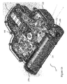
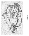
- Figures 3a-3c show an example of how two stud modules 20 can be mounted in the casing 201 in connection with the manufacture.
- the casing has slightly smaller openings than the maximum diameter of the stud modules, to which openings the stud modules can be directly mounted by "dropping".
- the stud modules must be, of course, pressed into their places, so that the gears click in their places between the gear of the casing and both stud module gears. The result (naturally without the other parts at this stage) is seen in Figure 3b .
- the heel unit i.e. in its operation mode seen from below it, the situation is according to Figure 3c .
- the space taken by the battery is shown as a half-cylindrical space of the left edge of Figure 3c .
- Figure 4 shows a principled picture of a shoe sole according to the invention seen from below as a cross-section, i.e. as a horizontal cross-sectional view in a case, where the studs have been located also elsewhere than in the heel part of the shoe.
- an electric motor 107 e.g. a vibra motor
- the electric motor 107 has a rotating central axis, which is vertical in the Figure.
- the end of the rotating central axis of the electric motor is, on its part, connected e.g. to a cylindrical drum 41, to the outer surface of which threads have been manufactured.
- the operation of the motor 107 is controlled by a controller-drive circuit-combination carried out on a circuit board, which combination is disclosed in Figure 4 in a simplified manner with an element 16, which at the desired times supplies battery power to the electric motor 107.
- a circuit board the substantial component of which is the control logic, i.e. the controller, can be located in the heel unit of the shoe. Additionally, a memory unit is needed, and a possibility to set and, where necessary, to change the parameters used by the controller. The parameters are discussed in more detail below in connection with the activation of the change of the operation mode.
- the power can also be transmitted with gears.
- gears or cog wheels can be chained, mounted in appropriate angles in relation to each other, so that each stud module can be reached with said gears. This way, the rotational energy of the electric motor 107 can be transmitted to a movement of a stud turning outwards and inwards of the stud module located anywhere in the shoe sole, corresponding to the active and passive operation mode of the shoe.
- a push bar which moves in a longitudinal direction with the aid of a rotational motion given by the electric motor, can be used, by utilizing cog wheels, other kind of gears, such as a bevel gear (or bevel gears), and the idea to be described next in Figure 5 , can also be used with a push bar for turning the stud in order to change the operation modes.
- a more commonly defined power transmission plate which can be moved or rotated into a desired direction in order to transmit power further in the element chain, can be used as a power transmission element.
- a stud cylinder 500 located in a stud module and necessary for changing the operation mode of the studs is shown as an example.
- the stud cylinder 500 has a casing 502, inside of which a stud 510 to be moved in and out has been fitted.
- the stud is a cylindrical part, in the middle of which there is a longitudinal hole 512 extending from the first end of the stud close to the second end of the stud.
- a channel 506 in which the cylindrical part of the stud is fitted to move.
- control protrusions 514 protruding in the opposite directions from the level of the cylindrical outer surface, the free ends of which protrusions are fitted into spiral-like grooves 516 in the inner wall of the cavity 504.
- the control disc has a circular plate-like base part, in the outer edge of which there is a cogging, which is compatible with the threads on the outer surface of the threaded bar.
- the base part On the surface of the base part, which surface is on the side of the cavity, there is a pin 518, the free end of which extends into the hole 512 located in the middle of the stud.
- the outer surface of the pin has a shape, which is compatible with the inner surface of the hole of the stud, so that the pin can move in the hole in the longitudinal direction of the pin, but it cannot rotate inside the hole around its longitudinal axis.
- Rotating the control disc thus also makes the stud rotate around its longitudinal axis.
- the stud 510 Depending on the rotating direction of the control disc, the stud 510 thus moves forced by the control protrusions 514 of the stud running in the spiral grooves of the cavity walls, either upwards towards the passive operation mode or downwards towards the active operation mode.
- the shoe sole thus comprises a printed circuit board 601, which functions an intelligence of the device.
- the circuit board i.e. the electronic module 601
- the circuit board is located in the heel unit on the casing.
- Figure 1b This is also shown in Figure 1b in the structure, where electric components are illustrated as rectangular elements.
- the above-mentioned memory element can be located on the circuit board for saving the parameters necessary for the control logic.
- the circuit board 601 can be preferably located in the direction of the long side of the heel part, i.e.
- the battery i.e. the power source
- the battery is located instead of the heel part in the leg of the shoe inside its upper. This alternative is, of course, useful mainly when the shoe has a longer leg part, so that the battery can be easily located therein without disturbing the user.
- the battery could be easily located, for example, into the leg part of the shoe inside the leather lining of the ankle boot-like shoe.
- a connection from the battery to the electric motor must be created, and if the electric motor is located in the shoe heel in the heel unit, connecting conductors are needed for a longer distance from the battery of the leg to the heel of the shoe.
- This embodiment gives more space to the heel unit, and for example a greater number of stud modules than the two modules in the above-mentioned example could then be located in the heel part of the shoe.
- the benefit of the embodiment is also the fact that the size of the shoe heel does not limit the physical size of the battery.
- the electric motor acting as a power source is located in the upper part of the shoe, i.e. elsewhere in the shoe than in its sole.
- the power is transmitted through the motor axis and the power transmission means (as described above) to the stud units and through that way to the actual studs.
- This exemplary embodiment makes it possible to have even more space in the shoe sole, e.g. for locating even a greater number of studs to the sole area.
- the battery is located in the upper part of shoe in the immediate vicinity of the electric motor, so that the necessary connections can be made by a simple arrangement.
- the power supply system is, instead of an electric motor, a mechanism, with which the necessary energy can be generated.
- This mechanism can get its energy e.g. from the movement of the shoe or from solar energy.
- the manner of the energy supply is not especially limited by the invention, but the substantial general principle is the activation of the transfer mechanism of the studs caused by the exceeding of the measurement result given by the acceleration sensor.
Landscapes
- Engineering & Computer Science (AREA)
- Microelectronics & Electronic Packaging (AREA)
- Footwear And Its Accessory, Manufacturing Method And Apparatuses (AREA)
Claims (15)
- Ein Verfahren zur Steuerung des Betriebs eines Transfermechanismus von mindestens einem Bolzen (203, 510), der in einer Schuhsohle angeordnet ist, wobei mit dem Transfermechanismus der mindestens eine Bolzen (203, 510), der in der Schuhsohle angeordnet ist, verschoben werden kann zwischen einem aktiven Betriebsmodus und einem passiven Betriebsmodus, wobei der Transfermechanismus für mindestens einen Bolzen von dem aktiven Betriebsmodus zu dem passiven Betriebsmodus und ungekehrt aktiviert wird, wenn ein Signal, das von einem Beschleunigungssensor (111), welcher in der Schuhsohle angeordnet ist, einen bestimmten Beschleunigungsgrenzwert mindestens zweimal in Folge während eines bestimmten zweiten Zeitfensters überschreitet als Ergebnis einer Trittbewegung, die durch den Benutzer ausgeführt wird, und weiterhin wenn das genannte Signal anzeigt, dass die Richtung der Ebene der Schuhsohle sich wesentlich unterscheidet von der horizontalen Ebene mindestens in einem bestimmten ersten Zeitfenster.
- Verfahren gemäß Anspruch 1, dadurch gekennzeichnet, dass eine Steuerungslogik (601), die im Schuh angeordnet ist, dazu ausgelegt ist, den Transfermechanismus des Bolzens zu aktivieren, wenn das Signal, das von dem Beschleunigungssensor gemessen (111) wird, einen bestimmten Grenzwert mindestens zweimal in Folge während eines bestimmten zweiten Zeitfensters überschreitet als Ergebnis einer doppelten Trittbewegung, die durch den Benutzer ausgeführt wird.
- Verfahren gemäß Anspruch 1 oder 2, dadurch gekennzeichnet, dass der Transfermechanismus von einer Stromquelle (104) gespeist wird, die im Schuh angeordnet ist, wobei die Stromquelle einen elektrischen Motor (107) speist als eine Funktion eines Steuerungssignals, das von der Steuerungslogik (601) gegeben wird, wobei in der Funktion das Steuersignal aktiviert wird basierend auf der Messinformation des Beschleunigungssensors (111).
- Verfahren gemäß einem der Ansprüche 1-3, dadurch gekennzeichnet, dass der genannte Beschleunigungsgrenzwert und die genannten Längen des ersten und zweiten Zeitfensters entweder Benutzer-spezifisch oder Benutzergruppen-spezifisch eingestellt werden kann oder als ein konstanter Wert.
- Eine Schuhsohle, an der mindestens ein beweglicher Bolzen (203, 510) angeordent ist, und wobei die Schuhsohle einen Transfermechanismus der Bolzen umfasst, welcher das Verschieben von mindestens einem Bolzen (203, 510) zwischen aktiven Betriebsmodus und einem passiven Betriebsmodus ermöglicht, dadurch gekennzeichnet, dass die Schuhsohle mindestens einen Beschleunigungssensor (111) umfasst, von dem aus es eine Verbindung zu dem Transfermechansimus gibt, und welcher eingerichtet ist, den Betriebsmodus des Bolzens zu ändern, wenn das von dem Beschleunigungssensor gemessene Signal einen bestimmten Beschleunigungsgrenzwert überschreitet mindestens zweimal in Folge während eines bestimmten zweiten Zeitfensters überschreitet als Ergebnis einer Trittbewegung, die durch den Benutzer ausgeführt wird, und weiterhin wenn das genannte Signal anzeigt, dass die Richtung der Ebene der Schuhsohle sich wesentlich unterscheidet von der horizontalen Ebene mindestens in einem bestimmten ersten Zeitfenster.
- Schuhsohle gemäß Anspruch 5, dadurch gekennzeichnet, dass der Schuh eine Steuerungslogik (601) umfasst, die dazu ausgelegt ist, den Transfermechanismus des Bolzens zu aktivieren, wenn das Signal, das von dem Beschleunigungssensor gemessen (111) wird, einen bestimmten Grenzwert mindestens zweimal in Folge während eines bestimmten zweiten Zeitfensters überschreitet als Ergebnis einer doppelten Trittbewegung, die durch den Benutzer ausgeführt wird.
- Schuhsohle gemäß Anspruch 5 oder 6, dadurch gekennzeichnet, dass jeder Bolzen (203) zu einem separaten Bolzenmodul (101, 102, 20) ausgelegt ist.
- Schuhsohle gemäß Anspruch 7, dadurch gekennzeichnet, dass die Schuhsohle eine Ferseneinheit (10) umfasst, welche in der Schuhferse angeordnet ist, wobei die Ferseneinheit (10) mindestens ein Bolzenmodul (101, 102, 20) umfasst.
- Schuhsohle gemäß Anspruch 8, dadurch gekennzeichnet, dass die Ferseneinheit (10) eine Stromquelle (104) aufweist und einen elektrischen Motor (107) zur Erzeugung einer Rotationsenergie und eine Steuerungslogik (601), welche ausgelegt ist, Messinformationen von dem Beschleunigungssensor (111) zu erhalten und ein Steuerungssignal an den elektrischen Motor (107) zu geben, das auf den Messinformationen basiert.
- Schuhsohle gemäß einem der vorhergehenden Ansprüche 5-8, dadurch gekennzeichnet, dass die Stromversorgung zu dem elektrischen Motor (107), der in der Ferseneinheit (10) angeordnet ist, von außerhalb der Schuhsohle kommt.
- Schuhsohle gemäß einem der vorhergehenden Ansprüche 5-8, dadurch gekennzeichnet, dass die Stromversorgung (104) und der elektrische Motor (107) außerhalb der Sohle in einem oberen Teil des Schuhs angeordnet sind, und dass es Verbindungen gibt von der Stromquelle und dem elektrischen Motor zu dem mindestens einem Bolzenmodul (101, 102, 20).
- Schuhsohle gemäß einem der vorhergehenden Ansprüche 5-11, dadurch gekennzeichnet, dass der Transfermechanismus mindestens ein Kraftübertragungselement (108, 109, 205) aufweist zur Übertragung des von der Steuerungslogik (601) gegebenen Signals von dem elektrischen Motor (107) in eine Bewegung von mindestens einem Bolzen (203, 510) zwischen den aktiven und dem passiven Betriebsmodus.
- Schuhsohle gemäß Anspruch 12, dadurch gekennzeichnet, dass das Kraftübertragungselement ein Zahnrad (109, 205), Kegelrad (108), Getriebeplatte, eine gezahnte Stange (40) oder eine Druckstange ist, die an ihrer äußeren Oberfläche mit einem Gewinde versehen ist.
- Schuhsohle gemäß Anspruch 13, dadurch gekennzeichnet, dass mindestens zwei Bolzenmodule (101, 102, 20) in der Schuhsohle derart angeordnet sind, dass sie mit mindestens einer Zahn- oder Druckstange, die als ein Teil des Transfermechanismus wirkt, kontaktiert, wobei in jedem Kontakt jedes Bolzenmodul (101, 102, 20) ein Zahnrad (205) und Bolzensteuerungseinrichtungen (514, 516) aufweist, die in genanntem Kontakt sind, um den Bolzen in eine Längsbewegung zu bringen, die durch das Steuerungssignal ausgelöst wird.
- Schuhsohle gemäß einem der vorhergehenden Ansprüche 5-14, dadurch gekennzeichnet, dass der Schuh eine Batterie umfasst, wobei die Batterie innerhalb des Oberen des Beinteils des Schuhs angeordnet ist, und wobei die elektrische Verbindung von der Batterie zu dem elektrischen Motor (107), der in der Schuhferse angeordnet ist, hergestellt wird durch Kabel innerhalb der Oberseite des Schuhs.
Applications Claiming Priority (1)
| Application Number | Priority Date | Filing Date | Title |
|---|---|---|---|
| FI20145529A FI125742B (fi) | 2014-06-09 | 2014-06-09 | Jalkineen nastamekanismi ja jalkine |
Publications (2)
| Publication Number | Publication Date |
|---|---|
| EP2954796A1 EP2954796A1 (de) | 2015-12-16 |
| EP2954796B1 true EP2954796B1 (de) | 2016-11-30 |
Family
ID=53373307
Family Applications (1)
| Application Number | Title | Priority Date | Filing Date |
|---|---|---|---|
| EP15170796.5A Active EP2954796B1 (de) | 2014-06-09 | 2015-06-05 | Bolzenmechanismus für einen schuh sowie schuh |
Country Status (2)
| Country | Link |
|---|---|
| EP (1) | EP2954796B1 (de) |
| FI (1) | FI125742B (de) |
Cited By (1)
| Publication number | Priority date | Publication date | Assignee | Title |
|---|---|---|---|---|
| KR20170142828A (ko) * | 2016-06-17 | 2017-12-28 | 주식회사 트렉스타 | 스파이크 슈즈 |
Families Citing this family (4)
| Publication number | Priority date | Publication date | Assignee | Title |
|---|---|---|---|---|
| CN106263256B (zh) * | 2016-08-08 | 2018-07-06 | 浙江吉利控股集团有限公司 | 带充气功能的减震鞋底结构 |
| CN106213654B (zh) * | 2016-08-08 | 2018-07-03 | 浙江吉利控股集团有限公司 | 模块化鞋底结构 |
| CN113558333B (zh) * | 2021-06-30 | 2022-10-11 | 杭州电子科技大学 | 一种可自适应调整防滑度的智能鞋 |
| IT202100019202A1 (it) * | 2021-07-20 | 2023-01-20 | Nicolas Pirino | Sistema elettromeccanico anticaduta e antislittamento per una calzatura |
Family Cites Families (6)
| Publication number | Priority date | Publication date | Assignee | Title |
|---|---|---|---|---|
| FI6772A (fi) | 1917-10-04 | Orientaliska Cigarettfabr Ab | Cigarettförpackning | |
| US4873774A (en) | 1988-03-01 | 1989-10-17 | Universal Plastics Incorporated | Shoe sole with retractable cleats |
| US6125556A (en) | 1997-06-20 | 2000-10-03 | Peckler; Stephen N. | Golf shoe with high liquid pressure spike ejection |
| US7788828B2 (en) * | 2006-05-10 | 2010-09-07 | Krouse Wayne F | Active shoe cleat system |
| DE102006028666A1 (de) | 2006-06-22 | 2007-12-27 | Thielen Feinmechanik Gmbh | Schuhsohle mit integrierten Gleitschutzelementen |
| FI123280B (fi) | 2011-06-10 | 2013-01-31 | Sievin Jalkine Oy | Menetelmä jalkineen nastan siirtomekanismin ohjaamiseksi ja jalkine |
-
2014
- 2014-06-09 FI FI20145529A patent/FI125742B/fi active IP Right Grant
-
2015
- 2015-06-05 EP EP15170796.5A patent/EP2954796B1/de active Active
Non-Patent Citations (1)
| Title |
|---|
| None * |
Cited By (2)
| Publication number | Priority date | Publication date | Assignee | Title |
|---|---|---|---|---|
| KR20170142828A (ko) * | 2016-06-17 | 2017-12-28 | 주식회사 트렉스타 | 스파이크 슈즈 |
| KR101865083B1 (ko) * | 2016-06-17 | 2018-06-07 | 주식회사 트렉스타 | 스파이크 슈즈 |
Also Published As
| Publication number | Publication date |
|---|---|
| FI125742B (fi) | 2016-01-29 |
| EP2954796A1 (de) | 2015-12-16 |
Similar Documents
| Publication | Publication Date | Title |
|---|---|---|
| EP2954796B1 (de) | Bolzenmechanismus für einen schuh sowie schuh | |
| US11666462B2 (en) | System for control of a prosthetic device | |
| US9558399B1 (en) | Feedback device to improve arm swing | |
| EP2429459B1 (de) | System, verfahren und vorrichtung zur steuerung einer prothese | |
| CA2930858C (en) | Heated insole with removable and rechargeable battery | |
| CN109414092B (zh) | 在鞋类中使用磁体进行足部存在感测 | |
| US9826933B2 (en) | System for control of a prosthetic device | |
| EP3061435B1 (de) | Unterstützendes antriebssystem für einen rollstuhl | |
| US20120259255A1 (en) | Non-invasive, vibrotactile medical device to restore normal gait for patients suffering from peripheral neuropathy | |
| US20150359699A1 (en) | Electric walking assistant device | |
| JP2018531063A (ja) | 自動義手 | |
| US20180263534A1 (en) | Fall detection device and method for controlling thereof | |
| KR101856053B1 (ko) | 위험상황에 대처하기 위한 신발 패드 및 이를 이용한 위험 상황 판단 방법 | |
| WO2003002218A1 (en) | Pole | |
| EP3042840A1 (de) | Berührungslose betriebsvorrichtung für ein fahrrad | |
| EP3752260B1 (de) | Vorrichtung zur überwachung der sportleistung, insbesondere der fussballleistung | |
| KR102188302B1 (ko) | 보행 보조 시스템 | |
| KR100485496B1 (ko) | 어깨 움직임을 이용한 척추 손상 장애인용 전동 휠체어조종센서 및 이를 이용한 휠체어 구동제어장치 | |
| KR101305909B1 (ko) | 자동속도 제어형 보행기 | |
| US20160001163A1 (en) | Secure attachment of a shoe on a ski | |
| CN214435782U (zh) | 一种穿戴式驾驶防瞌睡装置 | |
| KR102107583B1 (ko) | 보행 보조 기구 | |
| US20240009007A1 (en) | System for control of a prosthetic device | |
| CN224140257U (zh) | 智能防跌倒鞋底 | |
| US20250041662A1 (en) | Wearable device for measuring sports performance |
Legal Events
| Date | Code | Title | Description |
|---|---|---|---|
| PUAI | Public reference made under article 153(3) epc to a published international application that has entered the european phase |
Free format text: ORIGINAL CODE: 0009012 |
|
| AK | Designated contracting states |
Kind code of ref document: A1 Designated state(s): AL AT BE BG CH CY CZ DE DK EE ES FI FR GB GR HR HU IE IS IT LI LT LU LV MC MK MT NL NO PL PT RO RS SE SI SK SM TR |
|
| AX | Request for extension of the european patent |
Extension state: BA ME |
|
| 17P | Request for examination filed |
Effective date: 20160516 |
|
| GRAP | Despatch of communication of intention to grant a patent |
Free format text: ORIGINAL CODE: EPIDOSNIGR1 |
|
| RBV | Designated contracting states (corrected) |
Designated state(s): AL AT BE BG CH CY CZ DE DK EE ES FI FR GB GR HR HU IE IS IT LI LT LU LV MC MK MT NL NO PL PT RO RS SE SI SK SM TR |
|
| INTG | Intention to grant announced |
Effective date: 20160623 |
|
| GRAS | Grant fee paid |
Free format text: ORIGINAL CODE: EPIDOSNIGR3 |
|
| GRAA | (expected) grant |
Free format text: ORIGINAL CODE: 0009210 |
|
| AK | Designated contracting states |
Kind code of ref document: B1 Designated state(s): AL AT BE BG CH CY CZ DE DK EE ES FI FR GB GR HR HU IE IS IT LI LT LU LV MC MK MT NL NO PL PT RO RS SE SI SK SM TR |
|
| REG | Reference to a national code |
Ref country code: CH Ref legal event code: EP Ref country code: GB Ref legal event code: FG4D |
|
| REG | Reference to a national code |
Ref country code: AT Ref legal event code: REF Ref document number: 848962 Country of ref document: AT Kind code of ref document: T Effective date: 20161215 |
|
| REG | Reference to a national code |
Ref country code: IE Ref legal event code: FG4D |
|
| REG | Reference to a national code |
Ref country code: DE Ref legal event code: R096 Ref document number: 602015000850 Country of ref document: DE |
|
| PG25 | Lapsed in a contracting state [announced via postgrant information from national office to epo] |
Ref country code: LV Free format text: LAPSE BECAUSE OF FAILURE TO SUBMIT A TRANSLATION OF THE DESCRIPTION OR TO PAY THE FEE WITHIN THE PRESCRIBED TIME-LIMIT Effective date: 20161130 |
|
| REG | Reference to a national code |
Ref country code: SE Ref legal event code: TRGR |
|
| REG | Reference to a national code |
Ref country code: LT Ref legal event code: MG4D |
|
| REG | Reference to a national code |
Ref country code: NL Ref legal event code: MP Effective date: 20161130 |
|
| REG | Reference to a national code |
Ref country code: AT Ref legal event code: MK05 Ref document number: 848962 Country of ref document: AT Kind code of ref document: T Effective date: 20161130 |
|
| REG | Reference to a national code |
Ref country code: NO Ref legal event code: T2 Effective date: 20161130 |
|
| PG25 | Lapsed in a contracting state [announced via postgrant information from national office to epo] |
Ref country code: GR Free format text: LAPSE BECAUSE OF FAILURE TO SUBMIT A TRANSLATION OF THE DESCRIPTION OR TO PAY THE FEE WITHIN THE PRESCRIBED TIME-LIMIT Effective date: 20170301 Ref country code: LT Free format text: LAPSE BECAUSE OF FAILURE TO SUBMIT A TRANSLATION OF THE DESCRIPTION OR TO PAY THE FEE WITHIN THE PRESCRIBED TIME-LIMIT Effective date: 20161130 |
|
| PG25 | Lapsed in a contracting state [announced via postgrant information from national office to epo] |
Ref country code: RS Free format text: LAPSE BECAUSE OF FAILURE TO SUBMIT A TRANSLATION OF THE DESCRIPTION OR TO PAY THE FEE WITHIN THE PRESCRIBED TIME-LIMIT Effective date: 20161130 Ref country code: FI Free format text: LAPSE BECAUSE OF FAILURE TO SUBMIT A TRANSLATION OF THE DESCRIPTION OR TO PAY THE FEE WITHIN THE PRESCRIBED TIME-LIMIT Effective date: 20161130 Ref country code: AT Free format text: LAPSE BECAUSE OF FAILURE TO SUBMIT A TRANSLATION OF THE DESCRIPTION OR TO PAY THE FEE WITHIN THE PRESCRIBED TIME-LIMIT Effective date: 20161130 Ref country code: PL Free format text: LAPSE BECAUSE OF FAILURE TO SUBMIT A TRANSLATION OF THE DESCRIPTION OR TO PAY THE FEE WITHIN THE PRESCRIBED TIME-LIMIT Effective date: 20161130 Ref country code: HR Free format text: LAPSE BECAUSE OF FAILURE TO SUBMIT A TRANSLATION OF THE DESCRIPTION OR TO PAY THE FEE WITHIN THE PRESCRIBED TIME-LIMIT Effective date: 20161130 Ref country code: ES Free format text: LAPSE BECAUSE OF FAILURE TO SUBMIT A TRANSLATION OF THE DESCRIPTION OR TO PAY THE FEE WITHIN THE PRESCRIBED TIME-LIMIT Effective date: 20161130 Ref country code: PT Free format text: LAPSE BECAUSE OF FAILURE TO SUBMIT A TRANSLATION OF THE DESCRIPTION OR TO PAY THE FEE WITHIN THE PRESCRIBED TIME-LIMIT Effective date: 20170330 |
|
| PG25 | Lapsed in a contracting state [announced via postgrant information from national office to epo] |
Ref country code: NL Free format text: LAPSE BECAUSE OF FAILURE TO SUBMIT A TRANSLATION OF THE DESCRIPTION OR TO PAY THE FEE WITHIN THE PRESCRIBED TIME-LIMIT Effective date: 20161130 |
|
| PG25 | Lapsed in a contracting state [announced via postgrant information from national office to epo] |
Ref country code: DK Free format text: LAPSE BECAUSE OF FAILURE TO SUBMIT A TRANSLATION OF THE DESCRIPTION OR TO PAY THE FEE WITHIN THE PRESCRIBED TIME-LIMIT Effective date: 20161130 Ref country code: CZ Free format text: LAPSE BECAUSE OF FAILURE TO SUBMIT A TRANSLATION OF THE DESCRIPTION OR TO PAY THE FEE WITHIN THE PRESCRIBED TIME-LIMIT Effective date: 20161130 Ref country code: EE Free format text: LAPSE BECAUSE OF FAILURE TO SUBMIT A TRANSLATION OF THE DESCRIPTION OR TO PAY THE FEE WITHIN THE PRESCRIBED TIME-LIMIT Effective date: 20161130 Ref country code: RO Free format text: LAPSE BECAUSE OF FAILURE TO SUBMIT A TRANSLATION OF THE DESCRIPTION OR TO PAY THE FEE WITHIN THE PRESCRIBED TIME-LIMIT Effective date: 20161130 Ref country code: SK Free format text: LAPSE BECAUSE OF FAILURE TO SUBMIT A TRANSLATION OF THE DESCRIPTION OR TO PAY THE FEE WITHIN THE PRESCRIBED TIME-LIMIT Effective date: 20161130 |
|
| PG25 | Lapsed in a contracting state [announced via postgrant information from national office to epo] |
Ref country code: SM Free format text: LAPSE BECAUSE OF FAILURE TO SUBMIT A TRANSLATION OF THE DESCRIPTION OR TO PAY THE FEE WITHIN THE PRESCRIBED TIME-LIMIT Effective date: 20161130 Ref country code: BG Free format text: LAPSE BECAUSE OF FAILURE TO SUBMIT A TRANSLATION OF THE DESCRIPTION OR TO PAY THE FEE WITHIN THE PRESCRIBED TIME-LIMIT Effective date: 20170228 Ref country code: IT Free format text: LAPSE BECAUSE OF FAILURE TO SUBMIT A TRANSLATION OF THE DESCRIPTION OR TO PAY THE FEE WITHIN THE PRESCRIBED TIME-LIMIT Effective date: 20161130 Ref country code: BE Free format text: LAPSE BECAUSE OF FAILURE TO SUBMIT A TRANSLATION OF THE DESCRIPTION OR TO PAY THE FEE WITHIN THE PRESCRIBED TIME-LIMIT Effective date: 20161130 |
|
| REG | Reference to a national code |
Ref country code: DE Ref legal event code: R097 Ref document number: 602015000850 Country of ref document: DE |
|
| PLBE | No opposition filed within time limit |
Free format text: ORIGINAL CODE: 0009261 |
|
| STAA | Information on the status of an ep patent application or granted ep patent |
Free format text: STATUS: NO OPPOSITION FILED WITHIN TIME LIMIT |
|
| 26N | No opposition filed |
Effective date: 20170831 |
|
| PG25 | Lapsed in a contracting state [announced via postgrant information from national office to epo] |
Ref country code: SI Free format text: LAPSE BECAUSE OF FAILURE TO SUBMIT A TRANSLATION OF THE DESCRIPTION OR TO PAY THE FEE WITHIN THE PRESCRIBED TIME-LIMIT Effective date: 20161130 |
|
| PG25 | Lapsed in a contracting state [announced via postgrant information from national office to epo] |
Ref country code: MC Free format text: LAPSE BECAUSE OF FAILURE TO SUBMIT A TRANSLATION OF THE DESCRIPTION OR TO PAY THE FEE WITHIN THE PRESCRIBED TIME-LIMIT Effective date: 20161130 |
|
| REG | Reference to a national code |
Ref country code: IE Ref legal event code: MM4A |
|
| REG | Reference to a national code |
Ref country code: FR Ref legal event code: ST Effective date: 20180228 |
|
| PG25 | Lapsed in a contracting state [announced via postgrant information from national office to epo] |
Ref country code: LU Free format text: LAPSE BECAUSE OF NON-PAYMENT OF DUE FEES Effective date: 20170605 Ref country code: IE Free format text: LAPSE BECAUSE OF NON-PAYMENT OF DUE FEES Effective date: 20170605 |
|
| PG25 | Lapsed in a contracting state [announced via postgrant information from national office to epo] |
Ref country code: FR Free format text: LAPSE BECAUSE OF NON-PAYMENT OF DUE FEES Effective date: 20170630 |
|
| PG25 | Lapsed in a contracting state [announced via postgrant information from national office to epo] |
Ref country code: MT Free format text: LAPSE BECAUSE OF NON-PAYMENT OF DUE FEES Effective date: 20170605 |
|
| REG | Reference to a national code |
Ref country code: CH Ref legal event code: PL |
|
| PG25 | Lapsed in a contracting state [announced via postgrant information from national office to epo] |
Ref country code: CH Free format text: LAPSE BECAUSE OF NON-PAYMENT OF DUE FEES Effective date: 20180630 Ref country code: LI Free format text: LAPSE BECAUSE OF NON-PAYMENT OF DUE FEES Effective date: 20180630 |
|
| PG25 | Lapsed in a contracting state [announced via postgrant information from national office to epo] |
Ref country code: HU Free format text: LAPSE BECAUSE OF FAILURE TO SUBMIT A TRANSLATION OF THE DESCRIPTION OR TO PAY THE FEE WITHIN THE PRESCRIBED TIME-LIMIT; INVALID AB INITIO Effective date: 20150605 |
|
| PG25 | Lapsed in a contracting state [announced via postgrant information from national office to epo] |
Ref country code: CY Free format text: LAPSE BECAUSE OF FAILURE TO SUBMIT A TRANSLATION OF THE DESCRIPTION OR TO PAY THE FEE WITHIN THE PRESCRIBED TIME-LIMIT Effective date: 20161130 |
|
| PG25 | Lapsed in a contracting state [announced via postgrant information from national office to epo] |
Ref country code: MK Free format text: LAPSE BECAUSE OF FAILURE TO SUBMIT A TRANSLATION OF THE DESCRIPTION OR TO PAY THE FEE WITHIN THE PRESCRIBED TIME-LIMIT Effective date: 20161130 |
|
| GBPC | Gb: european patent ceased through non-payment of renewal fee |
Effective date: 20190605 |
|
| PG25 | Lapsed in a contracting state [announced via postgrant information from national office to epo] |
Ref country code: TR Free format text: LAPSE BECAUSE OF FAILURE TO SUBMIT A TRANSLATION OF THE DESCRIPTION OR TO PAY THE FEE WITHIN THE PRESCRIBED TIME-LIMIT Effective date: 20161130 |
|
| PG25 | Lapsed in a contracting state [announced via postgrant information from national office to epo] |
Ref country code: GB Free format text: LAPSE BECAUSE OF NON-PAYMENT OF DUE FEES Effective date: 20190605 |
|
| PG25 | Lapsed in a contracting state [announced via postgrant information from national office to epo] |
Ref country code: AL Free format text: LAPSE BECAUSE OF FAILURE TO SUBMIT A TRANSLATION OF THE DESCRIPTION OR TO PAY THE FEE WITHIN THE PRESCRIBED TIME-LIMIT Effective date: 20161130 Ref country code: IS Free format text: LAPSE BECAUSE OF FAILURE TO SUBMIT A TRANSLATION OF THE DESCRIPTION OR TO PAY THE FEE WITHIN THE PRESCRIBED TIME-LIMIT Effective date: 20170330 |
|
| P01 | Opt-out of the competence of the unified patent court (upc) registered |
Effective date: 20230519 |
|
| PGFP | Annual fee paid to national office [announced via postgrant information from national office to epo] |
Ref country code: DE Payment date: 20250618 Year of fee payment: 11 |
|
| PGFP | Annual fee paid to national office [announced via postgrant information from national office to epo] |
Ref country code: NO Payment date: 20250618 Year of fee payment: 11 |
|
| PGFP | Annual fee paid to national office [announced via postgrant information from national office to epo] |
Ref country code: SE Payment date: 20250618 Year of fee payment: 11 |