EP2954820B1 - Outil de nettoyage - Google Patents
Outil de nettoyage Download PDFInfo
- Publication number
- EP2954820B1 EP2954820B1 EP14748496.8A EP14748496A EP2954820B1 EP 2954820 B1 EP2954820 B1 EP 2954820B1 EP 14748496 A EP14748496 A EP 14748496A EP 2954820 B1 EP2954820 B1 EP 2954820B1
- Authority
- EP
- European Patent Office
- Prior art keywords
- fiber assembly
- base
- sheet
- cleaning
- sheet element
- Prior art date
- Legal status (The legal status is an assumption and is not a legal conclusion. Google has not performed a legal analysis and makes no representation as to the accuracy of the status listed.)
- Active
Links
- 238000004140 cleaning Methods 0.000 title claims description 126
- 239000000835 fiber Substances 0.000 claims description 208
- 238000003780 insertion Methods 0.000 claims description 41
- 230000037431 insertion Effects 0.000 claims description 41
- 238000000034 method Methods 0.000 claims description 25
- 238000004519 manufacturing process Methods 0.000 claims description 20
- 239000000463 material Substances 0.000 description 84
- 238000012986 modification Methods 0.000 description 17
- 230000004048 modification Effects 0.000 description 17
- -1 polypropylene Polymers 0.000 description 17
- 239000004698 Polyethylene Substances 0.000 description 12
- 229920000573 polyethylene Polymers 0.000 description 12
- 229920000139 polyethylene terephthalate Polymers 0.000 description 12
- 239000005020 polyethylene terephthalate Substances 0.000 description 12
- 239000004743 Polypropylene Substances 0.000 description 8
- 239000004745 nonwoven fabric Substances 0.000 description 8
- 229920001155 polypropylene Polymers 0.000 description 8
- ORQBXQOJMQIAOY-UHFFFAOYSA-N nobelium Chemical compound [No] ORQBXQOJMQIAOY-UHFFFAOYSA-N 0.000 description 5
- 238000000926 separation method Methods 0.000 description 5
- 239000000853 adhesive Substances 0.000 description 4
- 230000001070 adhesive effect Effects 0.000 description 4
- 238000005520 cutting process Methods 0.000 description 4
- 239000000428 dust Substances 0.000 description 4
- 238000010030 laminating Methods 0.000 description 4
- 238000003466 welding Methods 0.000 description 4
- 230000000694 effects Effects 0.000 description 3
- 238000005452 bending Methods 0.000 description 2
- 238000013461 design Methods 0.000 description 2
- 229920005989 resin Polymers 0.000 description 2
- 239000011347 resin Substances 0.000 description 2
- 238000012360 testing method Methods 0.000 description 2
- 229920001169 thermoplastic Polymers 0.000 description 2
- 239000004416 thermosoftening plastic Substances 0.000 description 2
- 239000004831 Hot glue Substances 0.000 description 1
- 239000004677 Nylon Substances 0.000 description 1
- 229920000297 Rayon Polymers 0.000 description 1
- 239000004676 acrylonitrile butadiene styrene Substances 0.000 description 1
- 238000002788 crimping Methods 0.000 description 1
- 239000004744 fabric Substances 0.000 description 1
- 239000013305 flexible fiber Substances 0.000 description 1
- 230000004927 fusion Effects 0.000 description 1
- 229940057995 liquid paraffin Drugs 0.000 description 1
- 238000002844 melting Methods 0.000 description 1
- 230000008018 melting Effects 0.000 description 1
- 229920001778 nylon Polymers 0.000 description 1
- 239000002964 rayon Substances 0.000 description 1
- 238000009958 sewing Methods 0.000 description 1
- 238000009751 slip forming Methods 0.000 description 1
- 229920002994 synthetic fiber Polymers 0.000 description 1
- 239000012209 synthetic fiber Substances 0.000 description 1
- 239000000057 synthetic resin Substances 0.000 description 1
- 229920003002 synthetic resin Polymers 0.000 description 1
- 239000004753 textile Substances 0.000 description 1
- 229920006346 thermoplastic polyester elastomer Polymers 0.000 description 1
- 238000005406 washing Methods 0.000 description 1
Images






Classifications
-
- A—HUMAN NECESSITIES
- A47—FURNITURE; DOMESTIC ARTICLES OR APPLIANCES; COFFEE MILLS; SPICE MILLS; SUCTION CLEANERS IN GENERAL
- A47L—DOMESTIC WASHING OR CLEANING; SUCTION CLEANERS IN GENERAL
- A47L13/00—Implements for cleaning floors, carpets, furniture, walls, or wall coverings
- A47L13/10—Scrubbing; Scouring; Cleaning; Polishing
- A47L13/16—Cloths; Pads; Sponges
-
- D—TEXTILES; PAPER
- D04—BRAIDING; LACE-MAKING; KNITTING; TRIMMINGS; NON-WOVEN FABRICS
- D04H—MAKING TEXTILE FABRICS, e.g. FROM FIBRES OR FILAMENTARY MATERIAL; FABRICS MADE BY SUCH PROCESSES OR APPARATUS, e.g. FELTS, NON-WOVEN FABRICS; COTTON-WOOL; WADDING ; NON-WOVEN FABRICS FROM STAPLE FIBRES, FILAMENTS OR YARNS, BONDED WITH AT LEAST ONE WEB-LIKE MATERIAL DURING THEIR CONSOLIDATION
- D04H1/00—Non-woven fabrics formed wholly or mainly of staple fibres or like relatively short fibres
- D04H1/40—Non-woven fabrics formed wholly or mainly of staple fibres or like relatively short fibres from fleeces or layers composed of fibres without existing or potential cohesive properties
- D04H1/54—Non-woven fabrics formed wholly or mainly of staple fibres or like relatively short fibres from fleeces or layers composed of fibres without existing or potential cohesive properties by welding together the fibres, e.g. by partially melting or dissolving
- D04H1/541—Composite fibres, e.g. sheath-core, sea-island or side-by-side; Mixed fibres
- D04H1/5412—Composite fibres, e.g. sheath-core, sea-island or side-by-side; Mixed fibres sheath-core
-
- A—HUMAN NECESSITIES
- A47—FURNITURE; DOMESTIC ARTICLES OR APPLIANCES; COFFEE MILLS; SPICE MILLS; SUCTION CLEANERS IN GENERAL
- A47L—DOMESTIC WASHING OR CLEANING; SUCTION CLEANERS IN GENERAL
- A47L13/00—Implements for cleaning floors, carpets, furniture, walls, or wall coverings
- A47L13/10—Scrubbing; Scouring; Cleaning; Polishing
- A47L13/38—Other dusting implements
-
- A—HUMAN NECESSITIES
- A47—FURNITURE; DOMESTIC ARTICLES OR APPLIANCES; COFFEE MILLS; SPICE MILLS; SUCTION CLEANERS IN GENERAL
- A47L—DOMESTIC WASHING OR CLEANING; SUCTION CLEANERS IN GENERAL
- A47L13/00—Implements for cleaning floors, carpets, furniture, walls, or wall coverings
- A47L13/10—Scrubbing; Scouring; Cleaning; Polishing
- A47L13/42—Details
- A47L13/46—Securing scouring or polishing cloths or sponges to the handles by gripping means, tongs, or the like
-
- B—PERFORMING OPERATIONS; TRANSPORTING
- B29—WORKING OF PLASTICS; WORKING OF SUBSTANCES IN A PLASTIC STATE IN GENERAL
- B29C—SHAPING OR JOINING OF PLASTICS; SHAPING OF MATERIAL IN A PLASTIC STATE, NOT OTHERWISE PROVIDED FOR; AFTER-TREATMENT OF THE SHAPED PRODUCTS, e.g. REPAIRING
- B29C65/00—Joining or sealing of preformed parts, e.g. welding of plastics materials; Apparatus therefor
- B29C65/66—Joining or sealing of preformed parts, e.g. welding of plastics materials; Apparatus therefor by liberation of internal stresses, e.g. shrinking of one of the parts to be joined
-
- B—PERFORMING OPERATIONS; TRANSPORTING
- B29—WORKING OF PLASTICS; WORKING OF SUBSTANCES IN A PLASTIC STATE IN GENERAL
- B29C—SHAPING OR JOINING OF PLASTICS; SHAPING OF MATERIAL IN A PLASTIC STATE, NOT OTHERWISE PROVIDED FOR; AFTER-TREATMENT OF THE SHAPED PRODUCTS, e.g. REPAIRING
- B29C66/00—General aspects of processes or apparatus for joining preformed parts
- B29C66/01—General aspects dealing with the joint area or with the area to be joined
- B29C66/344—Stretching or tensioning the joint area during joining
-
- B—PERFORMING OPERATIONS; TRANSPORTING
- B32—LAYERED PRODUCTS
- B32B—LAYERED PRODUCTS, i.e. PRODUCTS BUILT-UP OF STRATA OF FLAT OR NON-FLAT, e.g. CELLULAR OR HONEYCOMB, FORM
- B32B37/00—Methods or apparatus for laminating, e.g. by curing or by ultrasonic bonding
- B32B37/14—Methods or apparatus for laminating, e.g. by curing or by ultrasonic bonding characterised by the properties of the layers
-
- D—TEXTILES; PAPER
- D04—BRAIDING; LACE-MAKING; KNITTING; TRIMMINGS; NON-WOVEN FABRICS
- D04H—MAKING TEXTILE FABRICS, e.g. FROM FIBRES OR FILAMENTARY MATERIAL; FABRICS MADE BY SUCH PROCESSES OR APPARATUS, e.g. FELTS, NON-WOVEN FABRICS; COTTON-WOOL; WADDING ; NON-WOVEN FABRICS FROM STAPLE FIBRES, FILAMENTS OR YARNS, BONDED WITH AT LEAST ONE WEB-LIKE MATERIAL DURING THEIR CONSOLIDATION
- D04H3/00—Non-woven fabrics formed wholly or mainly of yarns or like filamentary material of substantial length
- D04H3/08—Non-woven fabrics formed wholly or mainly of yarns or like filamentary material of substantial length characterised by the method of strengthening or consolidating
- D04H3/14—Non-woven fabrics formed wholly or mainly of yarns or like filamentary material of substantial length characterised by the method of strengthening or consolidating with bonds between thermoplastic yarns or filaments produced by welding
- D04H3/147—Composite yarns or filaments
-
- B—PERFORMING OPERATIONS; TRANSPORTING
- B32—LAYERED PRODUCTS
- B32B—LAYERED PRODUCTS, i.e. PRODUCTS BUILT-UP OF STRATA OF FLAT OR NON-FLAT, e.g. CELLULAR OR HONEYCOMB, FORM
- B32B38/00—Ancillary operations in connection with laminating processes
- B32B38/0012—Mechanical treatment, e.g. roughening, deforming, stretching
- B32B2038/0028—Stretching, elongating
Definitions
- the present invention relates to a cleaning tool for cleaning an object to be cleaned.
- JP-A Japanese Unexamined Patent Application Publication
- JP-A No. 2007-111297 discloses a cleaning article having a grip insertion part and a fiber layer provided on each of the upper and lower sides of the grip insertion part.
- the grip insertion part is formed by a pair of grip attaching sheets. When used, the cleaning article is attached to a grip.
- Patent Document 1 JP-A No. 2007-111297
- the grip insertion part is formed by a pair of grip attaching sheets.
- the grip attaching sheets are in close contact with each other, an insertion opening for insertion of the grip is closed. Therefore, it is not user-friendly when a user attaches the grip to the cleaning article.
- a method of manufacturing a cleaning tool having a cleaning sheet and a holder for holding the cleaning sheet according to claim 1 is provided.
- the cleaning sheet has a base and a first fiber assembly connected to the base
- the method includes the steps of: stretching at least part of fibers of the first fiber assembly by applying a prescribed tension at least to the first fiber assembly; bonding the stretched first fiber assembly to the base; and forming a bent region in the base by releasing the application of tension from the first fiber assembly and thereby shrinking the fibers stretched by the tension, whereby the method includes a step of forming an insertion opening by the bent region.
- the prescribed tension applied to the first fiber assembly is applied to all of the fibers forming the first fiber assembly.
- the prescribed tension applied to the first fiber assembly is applied only to fibers in a region of the first fiber assembly which is bonded to the base.
- a prescribed tension is applied to the base in the step of bonding the stretched first fiber assembly to the base.
- the base is formed by a first sheet element.
- an insertion opening through which the holder is inserted is formed by superposing a second sheet element on the first sheet element and bonding the sheet elements.
- the step of forming the insertion opening by the bent region includes a step of superposing the first fiber assembly, the first sheet element and the second sheet element and a step of bonding the first fiber assembly, the first sheet element and the second sheet element, and the application of tension is released from the first fiber assembly after the insertion opening is formed.
- the step of forming the insertion opening by the bent region includes the steps of: bonding the first fiber assembly and the first sheet element, forming a bent region in the first sheet element by releasing the application of tension from the first fiber assembly; superposing the second sheet element on the first sheet element; and bonding the first sheet element and the second sheet element.
- the second sheet element has a second fiber assembly.
- the insertion opening is always kept open.
- the base and the first fiber assembly have different elastic constants.
- a method of manufacturing a cleaning tool and a cleaning sheet can be provided to facilitate attaching a holder to a cleaning element.
- FIGS. 1 to 8 A structure of a cleaning tool A as one embodiment of a "cleaning tool" according to the present invention is now explained.
- Objects to be cleaned by using the cleaning tool A typically include surfaces to be cleaned (floors, walls, windows, ceilings, external walls, furniture, clothes, curtains, bedding, lighting, home electric appliances, etc.) inside and outside of houses, apartments, buildings, factories, vehicles, etc. and surfaces of human body parts to be cleaned.
- the surfaces to be cleaned may be either flat or curved, uneven or stepped.
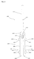
- the cleaning tool A includes a cleaning element holder 200 and a cleaning element 100.
- the cleaning element holder 200 is configured to be removably attached to the cleaning element 100 and to hold the cleaning element 100.
- the cleaning tool A, the cleaning element holder 200 and the cleaning element 100 are example embodiments that correspond to the "cleaning tool", the "holder” and the “cleaning sheet", respectively, according to this invention.
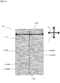
- the cleaning element 100 is configured to extend in a longitudinal direction Y and a transverse direction X crossing the longitudinal direction Y.
- the longitudinal direction Y is defined by a direction parallel to a direction of insertion of the cleaning element holder 200 into the cleaning element 100.
- the direction of insertion of the cleaning element holder 200 into the cleaning element 100 is defined as an inserting direction Y1, and a direction opposite to the inserting direction Y1 is defined as a pulling-out direction Y2.
- a direction crossing the longitudinal direction Y and the transverse direction X is defined as a thickness direction Z.
- crossing means “perpendicularly crossing” unless otherwise specified.
- a center point of the cleaning element 100 in the transverse direction X is defined as a transverse direction center point XCP.
- the transverse direction center point XCP can be formed on a line passing through any point on the cleaning element 100 in the transverse direction X.
- a line passing through the transverse direction center point XCP in parallel to the longitudinal direction Y is defined as a longitudinal center line YCL.
- a direction away from the transverse direction center point XCP of the cleaning element 100 is defined as an outside direction 100D1, and a direction toward the transverse direction center point XCP of the cleaning element 100 is defined as an inside direction 100D2.
- the cleaning element holder 200 mainly includes a handle part 210 and a cleaning element holding part 220.
- the handle part 210 is an elongate member to be held by a user during cleaning.
- the handle part 210 has a handle 211 and a handle connecting part 212.
- the handle connecting part 212 is connected to a connection part 230 of the cleaning element holding part 220.
- the handle 211 extends in an elongate form from the handle connecting part 212.
- the handle part 210 and the cleaning element holding part 220 are example embodiments that correspond to the "grip part" and the "holding part", respectively, according to this invention.
- the cleaning element holding part 220 is a member formed of resin material and configured to hold the cleaning element 100.
- the cleaning element holding part 220 mainly includes a pair of elongate holding members 221, a projection 260 and a retaining plate 270.
- polypropylene (PP) is used to form the cleaning element holding part 220.
- Flexible resin materials such as polyethylene (PE), polyethylene terephthalate (PET), acrylonitrile butadiene styrene (ABS) and thermoplastic polyester elastomer, can be appropriately selected for the cleaning element holding part 220.
- Each of the holding members 221 extends from the connection part 230 in a direction opposite to the direction in which the handle 211 extends.
- the holding member 221 has the connection part 230, a tip part 240 and an intermediate part 250 extending from the connection part 230 to the tip part 240.
- the tip part 240 of the holding member 221 is a free end.
- the projection 260 is formed in the outside direction 100D1 in the intermediate part 250.
- the projection 260 includes a first projection 261 formed on the connection part 230 side and a second projection 262 formed on the tip part 240 side.
- the retaining plate 270 protrudes from the connection part 230 and extends parallel to the pair holding members 221 therebetween.
- the retaining plate 270 is convexly curved downward, and further has an engagement lug (not shown) on the underside.
- the cleaning element 100 is now explained with reference to FIGS. 3 to 6 .
- the cleaning element 100 has a sheet-like form and has a dirt collecting function of collecting dust or dirt on an object to be cleaned. As shown in FIGS. 4 and 5 , the cleaning element 100 is rectangular in plan view.
- the cleaning element 100 may be of disposable type designed for single use, disposable type designed for multiple use which can be used several times, while holding dust or dirt collected from the cleaning surface to be cleaned, or reusable type which can be reused by washing.
- a base 120 of the cleaning element 100 is formed by a first sheet element 121.
- the base 120 has ends 120A in the transverse direction X and ends 120B in the longitudinal direction Y, and one side 120C and the other side 120D.
- the base 120, the first sheet element 121, the one side 120C and the other side 120D are example embodiments that correspond to the "base", the "first sheet element”, the “one side” and “the other side”, respectively, according to this invention.
- a fiber assembly 110GF is disposed on the one side 120C of the base 120.
- a second sheet element 122 is disposed on the other side 120D of the base 120.
- the base 120, the fiber assembly 110GF and the second sheet element 122 which are thus superposed one on the other extend in an elongate form in the longitudinal direction Y of the cleaning element 100.
- the fiber assembly 110GF forms a brush part 110 having a dirt collecting function.
- the fiber assembly 110GF and the brush part 110 are example embodiments that correspond to the "fiber assembly” and the "brush part", respectively, according to this invention.
- the fiber assembly 110GF which is disposed on the one side 120C of the base 120 like in the cleaning element 100 of this embodiment is defined as a first fiber assembly 110GF1.
- the first fiber assembly 110GF1 is an example embodiment that corresponds to the "first fiber assembly" according to this invention.
- the fiber assembly 110GF is formed by an assembly of fibers 110SF.
- the fiber 110SF is a single fiber structure formed by typical fibers, a fiber structure having typical fibers aligned in the length direction and/or the radial direction (twist yarn, spun yarn, yarn to which a plurality of filaments are partially connected), or an assembly of the fiber structures.
- the "typical fibers" as used herein are components of yarn, textile or the like and are thin and flexible fibers having a substantially longer length compared with the thickness. Typically, a long continuous fiber is defined as a filament and a short fiber as a staple.
- the fibers 110SF contain thermoplastic fibers in part and can be fusion bonded (or welded).
- the fiber assembly 110GF is formed of fibers 110SF which are arranged side by side along a prescribed direction of fiber orientation 110D and stacked in the thickness direction Z.
- the direction of fiber orientation 110D substantially coincides with the transverse direction X.
- the fibers 110SF are flexible and thus easily bent and deformed. Therefore, the direction of fiber orientation 110D of the fibers 110SF refers to the fiber orientation in design of the product.
- the fibers 110SF of the fiber assembly 110GF have a connection end 110SFA which is welded to a central bonded part 140. Further, the fibers 110SF have an open end 110SFB on the opposite side to the connection end 110SFA. The open end 110SFB is a free end.
- the fiber assembly 110GF is formed by three fiber layers, but the number of fiber layers may be one or more other than three as necessary.
- the fiber assembly 110GF has a planar structure having a predetermined flat or curved surface and has a three-dimensional form having a certain thickness or has a thin sheet-like form.
- the fiber assembly 110GF is typically formed of polyethylene (PE), polypropylene (PP), polyethylene terephthalate (PET), nylon, rayon or the like.
- PE polyethylene
- PP polypropylene
- PET polyethylene terephthalate
- nylon rayon or the like.
- an assembly of filaments formed by opening a tow is preferably used as the fiber assembly 110GF.
- the fiber assembly 110GF comprises conjugated fibers having a core of polypropylene (PP) or polyethylene terephthalate (PET) and a core covering sheath of polyethylene (PE).
- the fibers 110SF of the fiber assembly 110GF preferably have a fineness of 1 to 50 dtex, or more preferably 2 to 10 dtex.
- Each fiber assembly may contain fibers of substantially the same fineness, or it may contain fibers of different finenesses.
- oil is applied to the fiber assembly 110GF.
- the oil is mainly composed of liquid paraffin.
- the fiber assembly 110GF including the fibers 110SF having higher rigidity or the fibers 110SF having higher fineness. It is further preferred that the fiber assembly 110GF has crimped fibers.
- the crimped fibers are fibers subjected to a prescribed crimping process and easily intertwined with each other. By using such crimped fibers, the fiber assembly 110GF becomes bulkier than before the cleaning element holder 200 is attached to the cleaning element, and dust can be easily captured by the crimped portions. This structure can be realized especially by using crimped fibers opened from tows.
- the second sheet element 122 is a rectangular nonwoven fabric sheet which is shorter than the base 120 in the longitudinal direction Y.
- the base 120 (the first sheet element 121) and the second sheet element 122 are typically formed of sheet-like nonwoven fabric comprising thermal melting fibers (thermoplastic fibers). Therefore, the base 120 and the second sheet element 122 are also referred to as "nonwoven fabric sheet”. In order to enhance the sweeping-out function in cleaning, it is preferred to use the nonwoven fabric having higher rigidity.
- the nonwoven fabric is formed of synthetic fibers such as polyethylene (PE), polypropylene (PP) and polyethylene terephthalate (PET). Further, the nonwoven fabric is manufactured by through-air bonding or spun bonding.
- PE polyethylene
- PP polypropylene
- PET polyethylene terephthalate
- nonwoven fabric cloth or synthetic resin film may also be used.
- the base 120 and the second sheet element 122 are welded at the central bonded part 140 extending along the longitudinal center line YCL of the cleaning element 100, and at a plurality of first bonded parts 141 arranged on the both sides of the central bonded part 140.
- the base 120, the second sheet element 122 and the fiber assembly 110GF are welded at the central bonded part 140.
- the base 120, the second sheet element 122 and part of the fiber assembly 110GF are welded at the first bonded parts 141.
- the first bonded parts 141 located on the both end regions in the longitudinal direction Y are formed in positions where the second sheet element 122 does not exist. Therefore, the first bonded parts 141 located on the both end regions in the longitudinal direction Y only bond the base 120 and part of the fiber assembly 110GF.
- a pair of holding spaces 130 are formed between the base 120 and the second sheet element 122 in a region between the central bonded part 140 and the first bonded parts 141 and extend in the longitudinal direction Y.
- Each of the holding spaces 130 has insertion openings 131 on the both ends in the longitudinal direction Y.
- the holding space 130 and the insertion opening 131 are example embodiments that correspond to the "insertion part" and the "insertion opening” according to this invention.
- the holding spaces 130 are defined by a prescribed region of the base 120 and a prescribed region of the second sheet element 122 which extend between the pair first bonded parts 141 in the transverse direction X.
- the first bonded parts 141 are continuously formed substantially along the longitudinal direction Y. It is not necessary for adjacent ones of the first bonded parts 141 in the longitudinal direction Y to be aligned in the longitudinal direction Y.
- the arrangement pattern of the first bonded parts 141 can be appropriately designed according to the design and the shape of the cleaning element holding part 220. Naturally, the first bonded part 141 may also be formed in a continuous linear shape.
- the central bonded part 140 and the first bonded parts 141 are formed by heat welding.
- the bonded parts according to this invention may also be formed by ultrasonic welding, sewing or adhesives such as a hot-melt adhesive.
- Each of the insertion openings 131 has an insertion opening edge 132.
- the insertion opening edge 132 has a first edge region 132A formed in the base 120 and a second edge region 132B formed in the second sheet element 122.
- the first edge region 132A has a first bent region 120E formed by bending.
- the first bent region 120E is an example embodiment that corresponds to the "first bent region" according to this invention.
- the second edge region 132B has a second bent region 122E formed by bending.
- the first bent region 120E and the second bent region 122E are formed between the pair first bonded parts 141.
- the first bent region 120E is formed by making a portion of the base 120 (the first sheet element 121) between the first bonded parts 141 longer than the linear distance between the first bonded parts 141 in the transverse direction X.
- the second bent region 122E is formed by making a portion of the second sheet element 122 between the first bonded parts 141 longer than the linear distance between the first bonded parts 141 in the transverse direction X.
- the base 120 or the second sheet element 122 is "bent" in this invention means that it is “not straight”, and is bent, folded, deformed, curved or otherwise made uneven.
- the insertion opening 131 is formed by superposing the first bent region 120E and the second bent region 122E. Specifically, by provision of the first bent region 120E and the second bent region 122E, the insertion opening 131 is formed with a part where the base 120 and the second sheet element 122 do not come in contact with each other. This part forms a separation region 133.
- the insertion opening 131 is always kept open even when the holding part 220 is not inserted.
- the cleaning element 100 has strips 150.
- the strips 150 include first strips 151 formed between a plurality of cuts in the end regions of the base 120 in the transverse direction X, and second strips 152 formed between a plurality of cuts in the end regions of the second sheet element 122 in the transverse direction X.
- the cuts in the base 120 and the second sheet element 122 are formed in zigzag.
- the strips 150 may have a single kind or plural kinds of shapes appropriately selected from various shapes, such as zigzag, linear and curved shapes.
- the strips 150 only either one of the first strips 151 and the second strips 152 may be used.
- FIGS. 7 and 8 Engagement of the cleaning element holder 200 and the cleaning element 100 is explained with reference to FIGS. 7 and 8 .
- the holding members 221 can be inserted into the holding spaces 130.
- the cleaning element 100 is held by the cleaning element holder 200 by inserting the holding members 221 into the holding spaces 130 along the inserting direction Y1.
- the cleaning element holder 200 is pulled out of the holding spaces 130 along the pulling-out direction Y2.
- the projection 260 is located between the adjacent first bonded parts 141. As a result, the engagement between the cleaning element holder 200 and the cleaning element 100 is reliably maintained.
- the second sheet element 122 is held between the retaining plate 270 and the holding members 221.
- the separation region 133 is formed in the insertion opening 131. Therefore, when inserting the holding member 221 into the holding space 130, the user can readily recognize the position of the insertion opening 131. Specifically, the user can easily insert the tip part 240 of the holding member 221 through the insertion opening 131.
- the cleaning tool A of the present invention is user-friendly.
- FIGS. 9 to 17 A method of manufacturing the cleaning tool A according to the present invention is now explained with reference to FIGS. 9 to 17 .
- the fibers 110SF forming the fiber assembly 110GF according to the present invention is explained.
- FIG. 9 shows the fiber 110SF forming the fiber assembly 110GF, in a stationary state in which an external force is not applied.
- the fiber 110SF is crimped and thus has a zigzag shape having a plurality of bent parts 110SFC.
- the bent parts 110SFC are also referred to as crimps.
- FIG. 10 shows the fiber 110SF in which an external force (tension) is applied to the both ends in a direction away from each other.
- the fiber 110SF thus stretches as the distance between the bent parts 110SFC increases.
- the fiber 110SF returns from the stretched state shown in FIG. 10 to the stationary state shown in FIG. 9 .
- the base 120 and the fiber assembly 110GF have different modulus of elasticity in tension.
- the fiber assembly 110GF has a higher modulus of elasticity in tension (75.5%) than the base 120 (56.0%).
- the modulus of elasticity in tension was measured by the following test.
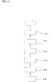
- FIG. 11 is a flow chart showing the manufacturing process.
- the manufacturing process includes a first step S11 of laminating materials for the base 120, the second sheet element 122 and part of the fiber assembly 110GF, a second step S12 of bonding the materials laminated in the first step S11, a third step S13 of laminating part of the fiber assembly 110GF on the materials bonded in the second step S12, a fourth step S14 of bonding the materials laminated in the third step S13, a fifth step S15 of cutting the materials bonded in the fourth step S14 into a prescribed shape, and a sixth step S16 of forming the bent region 120E in the base 120.
- the cleaning element 100 of this embodiment has the strips 150, but the manufacturing process of the strips 150 is not described for convenience of explanation.
- FIG. 12 shows the first step S11.
- a first sheet material 121A for forming the first sheet element 121 for the base 120 a second sheet material 122A for forming the second sheet element 122, and a first fiber assembly material 110GF1A for forming part of the first fiber assembly 110GF1 are fed.
- the first fiber assembly material 110GF1A is disposed on one side of the first sheet material 121A
- the second sheet material 122A is disposed on the other side of the first sheet material 121A.
- each material is supported by a support roller R and transferred in the machine direction M by a driving mechanism which is not shown.
- the direction of fiber orientation 110D of the first fiber assembly material 110GF1A generally coincides with the machine direction M.
- FIG. 13 shows the second step S12.
- the second sheet material 122A, the first sheet material 121A and the first fiber assembly material 110GF1A are all welded.
- the second sheet material 122A, the first sheet material 121A and the first fiber assembly material 110GF1A are welded at two parts in prescribed regions.
- the welded parts form a pair of the first bonded parts 141.
- FIG. 14 shows the third step S13.
- a second fiber assembly material 110GF1B is fed.
- the second fiber assembly material 110GF1B is fed onto one side of the first fiber assembly material 110GF1A on which the first sheet material 121A is not disposed.
- the direction of fiber orientation 110D of the second fiber assembly material 110GF1B generally coincides with the machine direction M.
- FIG. 15 shows the fourth step S14.
- the second sheet material 122A, the first sheet material 121A, the first fiber assembly material 110GF1A and the second fiber assembly material 110GF1B are all bonded by heat welding. This bonding is made at an intermediate part between the first bonded parts 140. This bonded part forms the central bonded part 140.
- a prescribed tension is applied to the first fiber assembly material 110GF1A.
- This is an example embodiment that corresponds to the "step of stretching at least part of fibers forming the first fiber assembly by applying a prescribed tension at least to the first fiber assembly" according to this invention.
- the first fiber assembly material 110GF1A to which the prescribed tension is applied is bonded to the first sheet material 121A for forming the base 120.
- This is an example embodiment that corresponds to the "step of bonding the stretched first fiber assembly to the base" according to this invention.
- the tension is applied to the first fiber assembly material 110GF1A in order to stabilize the shape of the first fiber assembly material 110GF1A and thereby facilitate manufacturing.
- the tension is applied to shrink the fibers 110SF of the fiber assembly material 110GF and form the bent region 120E in the base 120.
- this prescribed tension can also be applied to the second fiber assembly material 110GF1B.
- the fibers 110SF of the second fiber assembly material 110GF1B also shrink in a subsequent manufacturing step.
- the second fiber assembly material 110GF1B does not impede shrinkage of the first fiber assembly material 110GF1A.
- Tension is also applied to the first sheet material 121A and the second sheet material 122A to stabilize the shape.
- This is an example embodiment that corresponds to the feature that "a prescribed tension is applied to the base in the step of bonding the stretched first fiber assembly to the base" according to this invention.
- FIG. 16 shows the fifth step S15.
- the second sheet material 122A, the first sheet material 121A, the first fiber assembly material 110GF1A and the second fiber assembly material 110GF1B are cut at prescribed regions. By this cutting, the second sheet material 122A, the first sheet material 121A, the first fiber assembly material 110GF1A and the second fiber assembly material 110GF1B are released from tension.
- FIG. 17 shows the sixth step S16.
- the fibers 110SF of the first fiber assembly material 110GF1A released from tension shrink in the inside direction 100D2 in the transverse direction X.
- the distance between the pair bonded parts 141 in the transverse direction X is shortened as the fibers 110SF shrink.
- the bent region 120E is formed in the base 120.
- the bent region 122E is formed in the second sheet element 122. In this manner, the separation region 133 is formed in the insertion opening 131.
- the cleaning element 100 of the cleaning tool A according to the present invention is manufactured.
- the present invention is not limited to the above-described embodiment and manufacturing method, but rather, may be added to, changed, replaced with alternatives or otherwise modified.
- the holder 200 is provided with the two holding members 221, and correspondingly the cleaning element 100 is provided with the two holding spaces 130.
- a single holding space 130 may be provided for the two holding members 221, or a single holding member 221 and a single holding space 130 may be provided.
- a first modification is explained with reference to FIG. 18 .
- a cleaning element 101 of the first modification is different from the cleaning element 100 of the above-described embodiment in that the brush part 110 is formed not only on the one side 120C of the base 120, but also on the other side 120D of the base 120.
- a second fiber assembly 110GF2 is welded at the central region to form a second bonded part 142.
- the second fiber assembly 110GF2 having the second bonded part 142 is then bonded to the second sheet element 122 by an adhesive (not shown). In this manner, the cleaning element 101 is formed.
- a second modification is explained with reference to FIG. 19 .
- a cleaning element 102 of the second modification is different from the cleaning element 100 of the above-described embodiment in that the bent region 120E is formed only in the base 120.
- the first edge region 132A is longer than the second edge region 132B in the transverse direction X.
- the separation region 133 is formed in the insertion opening 131 by providing the bent region 120E in the base 120.
- FIG. 20 is a flow chart showing the manufacturing process for the cleaning element 102 of the second modification.
- the manufacturing process includes a first step S21 of laminating materials for the base 120 and part of the fiber assembly 110GF, a second step S22 of bonding the materials laminated in the first step S21, a third step S23 of laminating part of the fiber assembly 110GF on the materials bonded in the second step S22, a fourth step S24 of bonding the materials laminated in the third step S23, a fifth step S25 of cutting the materials bonded in the fourth step S24 into a prescribed shape, a sixth step S26 of forming the bent region 120E in the base 120, and a seventh step S27 of forming the insertion opening 131 by the bent region 120E.
- the cleaning element 102 of the second modification has the strips 150, but the manufacturing process of the strips 150 is not described for convenience of explanation.
- FIG. 21 shows the first step S21.
- the first sheet material 121A for forming the first sheet element 121 for the base 120 and the first fiber assembly material 110GF1A for forming part of the first fiber assembly 110GF1 are fed.
- the first fiber assembly material 110GF1A is disposed on one side of the first sheet material 121A.
- FIG. 22 shows the second step S22.
- the first sheet material 121A and the first fiber assembly material 110GF1A are all welded.
- the first sheet material 121A and the first fiber assembly material 110GF1A are welded at two parts in prescribed regions.
- the welded parts form a pair of the first bonded parts 141.
- FIG. 23 shows the third step S23.
- a second fiber assembly material 110GF1B is fed.
- the second fiber assembly material 110GF1B is fed onto one side of the first fiber assembly material 110GF1A on which the first sheet material 121A is not disposed.
- FIG. 24 shows the fourth step S24.
- the first sheet material 121A, the first fiber assembly material 110GF1A and the second fiber assembly material 110GF1B are all bonded by heat welding. This bonding is made at an intermediate part between the first bonded parts 141. This bonded part forms the central bonded part 140.
- FIG. 25 shows the fifth step S25.
- the first sheet material 121A, the first fiber assembly material 110GF1A and the second fiber assembly material 110GF1B are cut at prescribed regions. By this cutting, the first sheet material 121A, the first fiber assembly material 110GF1A and the second fiber assembly material 1 10GF1B are released from tension.
- FIG. 26 shows the sixth step S26.
- the fibers 110SF of the first fiber assembly material 110GF1A released from tension shrink in the inside direction 100D2 in the transverse direction X.
- the distance between the pair bonded parts 141 in the transverse direction X is shortened as the fibers 110SF shrink.
- the bent region 120E is formed in the base 120.
- FIG. 27 shows the seventh step S27.
- the second sheet element 122 having a prescribed shape is connected to the other side 120D of the base 120.
- the second sheet element 122 can be bonded to the base 120, for example, by an adhesive (not shown).
- the adhesive is applied to regions of the other side 120D of the base 120 corresponding to the central bonded part 140 and the first bonded parts 141.
- the cleaning tool A is an example embodiment that corresponds to the "cleaning tool” according to this invention.
- the cleaning element 100, 101, 102 is an example embodiment that corresponds to the "cleaning sheet” according to this invention.
- the cleaning element holder 200 is an example embodiment that corresponds to the "holder” according to this invention.
- the first fiber assembly 110GF1 is an example embodiment that corresponds to the "first fiber assembly” according to this invention.
- the base 120 is an example embodiment that corresponds to the "base” according to this invention.
- the bent region 120E is an example embodiment that corresponds to the "bent region” according to this invention.
- the fiber 110SF is an example embodiment that corresponds to the "fiber” according to this invention.
- the first sheet element 121 and the second sheet element 122 are example embodiments that correspond to the "first sheet element” and the “second sheet element", respectively, according to this invention.
- the insertion opening 131 is an example embodiment that corresponds to the "insertion opening” according to this invention.
- the one side 120C and the other side 120D are example embodiments that correspond to the "one side” and “the other side", respectively, according to this invention.
- the second fiber assembly 110GF2 is an example embodiment that corresponds to the "second fiber assembly” according to this invention.
- Embodiments and modifications of the present invention are not limited to those described above.
- the structures or features of the above-described embodiment and modifications can be appropriately used in combination, and can be added to, changed, replaced with alternatives or otherwise modified.
Landscapes
- Engineering & Computer Science (AREA)
- Textile Engineering (AREA)
- Mechanical Engineering (AREA)
- Cleaning Implements For Floors, Carpets, Furniture, Walls, And The Like (AREA)
- Nonwoven Fabrics (AREA)
Claims (11)
- Procédé de fabrication d'un outil de nettoyage (A) ayant une feuille de nettoyage (100, 101, 102) et un dispositif de maintien (200) pour maintenir la feuille de nettoyage (100, 101, 102), dans lequel la feuille de nettoyage (100, 101, 102) comporte une base (120) et un premier ensemble de fibres (110GF1) raccordé à la base (120), comprenant les étapes de :étirement d'au moins une partie des fibres (110SF) formant le premier ensemble de fibres (110GF1) en appliquant une tension prescrite au moins au premier ensemble de fibres (110GF1),liaison du premier ensemble de fibres étirées (110GF1) à la base (120), etformation d'une région coudée (120E) dans la base (120) en relâchant l'application de tension du premier ensemble de fibres (110GF1) et rétrécissant ainsi les fibres (110SF) étirées par la tension,tandis quele procédé est caractérisé en ce que le procédé comprend une étape de formation d'une ouverture d'insertion (131) par la région coudée (120E).
- Procédé selon la revendication 1, dans lequel la tension prescrite appliquée au premier ensemble de fibres (110GF1) est appliquée à toutes les fibres (110SF) formant le premier ensemble de fibres (110GF1).
- Procédé selon la revendication 1, dans lequel la tension prescrite appliquée au premier ensemble de fibres (110GF1) est appliquée uniquement à des fibres (110SF) dans une région du premier ensemble de fibres (110GF1) qui est lié à la base (120).
- Procédé selon l'une quelconque des revendications 1 à 3, dans lequel une tension prescrite est appliquée à la base (120) à l'étape de liaison du premier ensemble de fibres étirées (110GF1) à la base (120).
- Procédé selon l'une quelconque des revendications 1 à 4, dans lequel la base (120) comprend un premier élément de feuille (121).
- Procédé selon la revendication 5, dans lequel une ouverture d'insertion (131) à travers laquelle le dispositif de maintien (200) est inséré est formée en superposant un second élément de feuille (122) sur le premier élément de feuille (121) et en liant les éléments de feuille.
- Procédé selon l'une des revendications 1 à 6, dans lequel l'étape de formation de l'ouverture d'insertion (131) par la région coudée (120E) comprend une étape de superposition du premier ensemble de fibres (110GF1), du premier élément de feuille (121) et du second élément de feuille (122) et une étape de liaison du premier ensemble de fibres (110GF1), du premier élément de feuille (121) et du second élément de feuille (122), et dans lequel l'application de tension est relâchée du premier ensemble de fibres (110GF1) après que l'ouverture d'insertion (131) est formée.
- Procédé selon l'une des revendications 1 à 6, dans lequel l'étape de formation de l'ouverture d'insertion (131) par la région coudée (120E) comprend les étapes de :liaison du premier ensemble de fibres (110GF1) et du premier élément de feuille (121),formation d'une région coudée (120E) dans le premier élément de feuille (121) en relâchant l'application de tension du premier ensemble de fibres (110GF1),superposition du second élément de feuille (122) sur le premier élément de feuille (121), etliaison du premier élément de feuille (121) et du second élément de feuille (122).
- Procédé selon l'une quelconque des revendications 6 à 8, dans lequel le second élément de feuille (122) a un second ensemble de fibres (110GF2).
- Procédé selon l'une quelconque des revendications 1 à 9, dans lequel l'ouverture d'insertion (131) est toujours gardée ouverte.
- Procédé selon l'une quelconque des revendications 1 à 10, dans lequel la base (120) et le premier ensemble de fibres (110GF1) ont des constantes élastiques différentes.
Applications Claiming Priority (2)
| Application Number | Priority Date | Filing Date | Title |
|---|---|---|---|
| JP2013022755A JP6060000B2 (ja) | 2013-02-07 | 2013-02-07 | 清掃具 |
| PCT/JP2014/050859 WO2014122963A1 (fr) | 2013-02-07 | 2014-01-17 | Outil de nettoyage |
Publications (3)
| Publication Number | Publication Date |
|---|---|
| EP2954820A1 EP2954820A1 (fr) | 2015-12-16 |
| EP2954820A4 EP2954820A4 (fr) | 2016-11-23 |
| EP2954820B1 true EP2954820B1 (fr) | 2019-03-20 |
Family
ID=51299560
Family Applications (1)
| Application Number | Title | Priority Date | Filing Date |
|---|---|---|---|
| EP14748496.8A Active EP2954820B1 (fr) | 2013-02-07 | 2014-01-17 | Outil de nettoyage |
Country Status (5)
| Country | Link |
|---|---|
| US (1) | US9826875B2 (fr) |
| EP (1) | EP2954820B1 (fr) |
| JP (1) | JP6060000B2 (fr) |
| CN (1) | CN104981194B (fr) |
| WO (1) | WO2014122963A1 (fr) |
Family Cites Families (13)
| Publication number | Priority date | Publication date | Assignee | Title |
|---|---|---|---|---|
| US4720415A (en) * | 1985-07-30 | 1988-01-19 | Kimberly-Clark Corporation | Composite elastomeric material and process for making the same |
| US4823427A (en) | 1986-04-04 | 1989-04-25 | Kimberly-Clark Corporation | Elastic dust mop head cover |
| US6830800B2 (en) * | 1999-12-21 | 2004-12-14 | The Procter & Gamble Company | Elastic laminate web |
| US6946413B2 (en) * | 2000-12-29 | 2005-09-20 | Kimberly-Clark Worldwide, Inc. | Composite material with cloth-like feel |
| US20050120497A1 (en) * | 2003-12-03 | 2005-06-09 | The Procter & Gamble Company | Disposable, nonwoven cleaning wipes, and kits comprising them |
| US20050148260A1 (en) * | 2003-12-24 | 2005-07-07 | Kopacz Thomas J. | Highly textured non-woven composite wipe |
| JP4657075B2 (ja) | 2005-10-21 | 2011-03-23 | 花王株式会社 | 清掃用物品 |
| JP2009142358A (ja) * | 2007-12-12 | 2009-07-02 | Yamada Chiyoe | 清掃シートおよび清掃用具 |
| AU2010214462B2 (en) * | 2009-02-13 | 2013-12-19 | Kao Corporation | Cleaning sheet |
| US8857002B2 (en) * | 2009-06-19 | 2014-10-14 | Uni-Charm Corporation | Cleaning sheet and cleaning implement |
| US8578564B2 (en) * | 2009-11-05 | 2013-11-12 | The Procter & Gamble Company | Handle for removable cleaning implement |
| JP5548015B2 (ja) * | 2010-04-16 | 2014-07-16 | 菊夫 山田 | 清掃用シートおよび清掃具 |
| US8756746B2 (en) * | 2012-03-09 | 2014-06-24 | The Procter & Gamble | Cleaning article with elastically contracted sheet |
-
2013
- 2013-02-07 JP JP2013022755A patent/JP6060000B2/ja active Active
-
2014
- 2014-01-17 CN CN201480007826.9A patent/CN104981194B/zh not_active Expired - Fee Related
- 2014-01-17 WO PCT/JP2014/050859 patent/WO2014122963A1/fr not_active Ceased
- 2014-01-17 US US14/766,434 patent/US9826875B2/en active Active
- 2014-01-17 EP EP14748496.8A patent/EP2954820B1/fr active Active
Non-Patent Citations (1)
| Title |
|---|
| None * |
Also Published As
| Publication number | Publication date |
|---|---|
| JP6060000B2 (ja) | 2017-01-11 |
| EP2954820A4 (fr) | 2016-11-23 |
| CN104981194B (zh) | 2018-06-26 |
| JP2014150968A (ja) | 2014-08-25 |
| US9826875B2 (en) | 2017-11-28 |
| CN104981194A (zh) | 2015-10-14 |
| US20150374193A1 (en) | 2015-12-31 |
| EP2954820A1 (fr) | 2015-12-16 |
| WO2014122963A1 (fr) | 2014-08-14 |
Similar Documents
| Publication | Publication Date | Title |
|---|---|---|
| EP2954825B1 (fr) | Outil de nettoyage | |
| US10016114B2 (en) | Cleaning tool | |
| EP2954827B1 (fr) | Outil de nettoyage | |
| EP2954820B1 (fr) | Outil de nettoyage | |
| US10646095B2 (en) | Cleaning tool | |
| US10238262B2 (en) | Cleaning tool | |
| JP6346586B2 (ja) | 清掃具 | |
| JP5973930B2 (ja) | 清掃具 | |
| JP5968245B2 (ja) | 清掃具および清掃シートの製造方法 | |
| JP6195863B2 (ja) | 清掃具の製造方法および清掃シートの製造方法 | |
| JP6126399B2 (ja) | 清掃具および清掃シートの製造方法 | |
| JP6126397B2 (ja) | 清掃具 | |
| JP6239828B2 (ja) | 清掃具 | |
| JP2014150966A5 (fr) | ||
| JP2014150965A5 (fr) |
Legal Events
| Date | Code | Title | Description |
|---|---|---|---|
| PUAI | Public reference made under article 153(3) epc to a published international application that has entered the european phase |
Free format text: ORIGINAL CODE: 0009012 |
|
| 17P | Request for examination filed |
Effective date: 20150820 |
|
| AK | Designated contracting states |
Kind code of ref document: A1 Designated state(s): AL AT BE BG CH CY CZ DE DK EE ES FI FR GB GR HR HU IE IS IT LI LT LU LV MC MK MT NL NO PL PT RO RS SE SI SK SM TR |
|
| AX | Request for extension of the european patent |
Extension state: BA ME |
|
| DAX | Request for extension of the european patent (deleted) | ||
| A4 | Supplementary search report drawn up and despatched |
Effective date: 20161021 |
|
| RIC1 | Information provided on ipc code assigned before grant |
Ipc: A47L 13/16 20060101ALI20161017BHEP Ipc: D04H 3/147 20120101ALI20161017BHEP Ipc: A47L 13/20 20060101AFI20161017BHEP |
|
| GRAP | Despatch of communication of intention to grant a patent |
Free format text: ORIGINAL CODE: EPIDOSNIGR1 |
|
| STAA | Information on the status of an ep patent application or granted ep patent |
Free format text: STATUS: GRANT OF PATENT IS INTENDED |
|
| INTG | Intention to grant announced |
Effective date: 20181016 |
|
| GRAS | Grant fee paid |
Free format text: ORIGINAL CODE: EPIDOSNIGR3 |
|
| GRAA | (expected) grant |
Free format text: ORIGINAL CODE: 0009210 |
|
| STAA | Information on the status of an ep patent application or granted ep patent |
Free format text: STATUS: THE PATENT HAS BEEN GRANTED |
|
| AK | Designated contracting states |
Kind code of ref document: B1 Designated state(s): AL AT BE BG CH CY CZ DE DK EE ES FI FR GB GR HR HU IE IS IT LI LT LU LV MC MK MT NL NO PL PT RO RS SE SI SK SM TR |
|
| REG | Reference to a national code |
Ref country code: GB Ref legal event code: FG4D |
|
| REG | Reference to a national code |
Ref country code: CH Ref legal event code: EP |
|
| REG | Reference to a national code |
Ref country code: DE Ref legal event code: R096 Ref document number: 602014043265 Country of ref document: DE |
|
| REG | Reference to a national code |
Ref country code: AT Ref legal event code: REF Ref document number: 1109617 Country of ref document: AT Kind code of ref document: T Effective date: 20190415 |
|
| REG | Reference to a national code |
Ref country code: IE Ref legal event code: FG4D |
|
| REG | Reference to a national code |
Ref country code: NL Ref legal event code: MP Effective date: 20190320 |
|
| PG25 | Lapsed in a contracting state [announced via postgrant information from national office to epo] |
Ref country code: LT Free format text: LAPSE BECAUSE OF FAILURE TO SUBMIT A TRANSLATION OF THE DESCRIPTION OR TO PAY THE FEE WITHIN THE PRESCRIBED TIME-LIMIT Effective date: 20190320 Ref country code: FI Free format text: LAPSE BECAUSE OF FAILURE TO SUBMIT A TRANSLATION OF THE DESCRIPTION OR TO PAY THE FEE WITHIN THE PRESCRIBED TIME-LIMIT Effective date: 20190320 Ref country code: NO Free format text: LAPSE BECAUSE OF FAILURE TO SUBMIT A TRANSLATION OF THE DESCRIPTION OR TO PAY THE FEE WITHIN THE PRESCRIBED TIME-LIMIT Effective date: 20190620 Ref country code: SE Free format text: LAPSE BECAUSE OF FAILURE TO SUBMIT A TRANSLATION OF THE DESCRIPTION OR TO PAY THE FEE WITHIN THE PRESCRIBED TIME-LIMIT Effective date: 20190320 |
|
| REG | Reference to a national code |
Ref country code: LT Ref legal event code: MG4D |
|
| PG25 | Lapsed in a contracting state [announced via postgrant information from national office to epo] |
Ref country code: LV Free format text: LAPSE BECAUSE OF FAILURE TO SUBMIT A TRANSLATION OF THE DESCRIPTION OR TO PAY THE FEE WITHIN THE PRESCRIBED TIME-LIMIT Effective date: 20190320 Ref country code: GR Free format text: LAPSE BECAUSE OF FAILURE TO SUBMIT A TRANSLATION OF THE DESCRIPTION OR TO PAY THE FEE WITHIN THE PRESCRIBED TIME-LIMIT Effective date: 20190621 Ref country code: RS Free format text: LAPSE BECAUSE OF FAILURE TO SUBMIT A TRANSLATION OF THE DESCRIPTION OR TO PAY THE FEE WITHIN THE PRESCRIBED TIME-LIMIT Effective date: 20190320 Ref country code: HR Free format text: LAPSE BECAUSE OF FAILURE TO SUBMIT A TRANSLATION OF THE DESCRIPTION OR TO PAY THE FEE WITHIN THE PRESCRIBED TIME-LIMIT Effective date: 20190320 Ref country code: BG Free format text: LAPSE BECAUSE OF FAILURE TO SUBMIT A TRANSLATION OF THE DESCRIPTION OR TO PAY THE FEE WITHIN THE PRESCRIBED TIME-LIMIT Effective date: 20190620 Ref country code: NL Free format text: LAPSE BECAUSE OF FAILURE TO SUBMIT A TRANSLATION OF THE DESCRIPTION OR TO PAY THE FEE WITHIN THE PRESCRIBED TIME-LIMIT Effective date: 20190320 |
|
| REG | Reference to a national code |
Ref country code: AT Ref legal event code: MK05 Ref document number: 1109617 Country of ref document: AT Kind code of ref document: T Effective date: 20190320 |
|
| PG25 | Lapsed in a contracting state [announced via postgrant information from national office to epo] |
Ref country code: ES Free format text: LAPSE BECAUSE OF FAILURE TO SUBMIT A TRANSLATION OF THE DESCRIPTION OR TO PAY THE FEE WITHIN THE PRESCRIBED TIME-LIMIT Effective date: 20190320 Ref country code: AL Free format text: LAPSE BECAUSE OF FAILURE TO SUBMIT A TRANSLATION OF THE DESCRIPTION OR TO PAY THE FEE WITHIN THE PRESCRIBED TIME-LIMIT Effective date: 20190320 Ref country code: PT Free format text: LAPSE BECAUSE OF FAILURE TO SUBMIT A TRANSLATION OF THE DESCRIPTION OR TO PAY THE FEE WITHIN THE PRESCRIBED TIME-LIMIT Effective date: 20190720 Ref country code: CZ Free format text: LAPSE BECAUSE OF FAILURE TO SUBMIT A TRANSLATION OF THE DESCRIPTION OR TO PAY THE FEE WITHIN THE PRESCRIBED TIME-LIMIT Effective date: 20190320 Ref country code: RO Free format text: LAPSE BECAUSE OF FAILURE TO SUBMIT A TRANSLATION OF THE DESCRIPTION OR TO PAY THE FEE WITHIN THE PRESCRIBED TIME-LIMIT Effective date: 20190320 Ref country code: SK Free format text: LAPSE BECAUSE OF FAILURE TO SUBMIT A TRANSLATION OF THE DESCRIPTION OR TO PAY THE FEE WITHIN THE PRESCRIBED TIME-LIMIT Effective date: 20190320 Ref country code: EE Free format text: LAPSE BECAUSE OF FAILURE TO SUBMIT A TRANSLATION OF THE DESCRIPTION OR TO PAY THE FEE WITHIN THE PRESCRIBED TIME-LIMIT Effective date: 20190320 Ref country code: IT Free format text: LAPSE BECAUSE OF FAILURE TO SUBMIT A TRANSLATION OF THE DESCRIPTION OR TO PAY THE FEE WITHIN THE PRESCRIBED TIME-LIMIT Effective date: 20190320 |
|
| PG25 | Lapsed in a contracting state [announced via postgrant information from national office to epo] |
Ref country code: SM Free format text: LAPSE BECAUSE OF FAILURE TO SUBMIT A TRANSLATION OF THE DESCRIPTION OR TO PAY THE FEE WITHIN THE PRESCRIBED TIME-LIMIT Effective date: 20190320 Ref country code: PL Free format text: LAPSE BECAUSE OF FAILURE TO SUBMIT A TRANSLATION OF THE DESCRIPTION OR TO PAY THE FEE WITHIN THE PRESCRIBED TIME-LIMIT Effective date: 20190320 |
|
| PG25 | Lapsed in a contracting state [announced via postgrant information from national office to epo] |
Ref country code: IS Free format text: LAPSE BECAUSE OF FAILURE TO SUBMIT A TRANSLATION OF THE DESCRIPTION OR TO PAY THE FEE WITHIN THE PRESCRIBED TIME-LIMIT Effective date: 20190720 Ref country code: AT Free format text: LAPSE BECAUSE OF FAILURE TO SUBMIT A TRANSLATION OF THE DESCRIPTION OR TO PAY THE FEE WITHIN THE PRESCRIBED TIME-LIMIT Effective date: 20190320 |
|
| REG | Reference to a national code |
Ref country code: DE Ref legal event code: R097 Ref document number: 602014043265 Country of ref document: DE |
|
| PLBE | No opposition filed within time limit |
Free format text: ORIGINAL CODE: 0009261 |
|
| STAA | Information on the status of an ep patent application or granted ep patent |
Free format text: STATUS: NO OPPOSITION FILED WITHIN TIME LIMIT |
|
| PG25 | Lapsed in a contracting state [announced via postgrant information from national office to epo] |
Ref country code: DK Free format text: LAPSE BECAUSE OF FAILURE TO SUBMIT A TRANSLATION OF THE DESCRIPTION OR TO PAY THE FEE WITHIN THE PRESCRIBED TIME-LIMIT Effective date: 20190320 |
|
| 26N | No opposition filed |
Effective date: 20200102 |
|
| PG25 | Lapsed in a contracting state [announced via postgrant information from national office to epo] |
Ref country code: SI Free format text: LAPSE BECAUSE OF FAILURE TO SUBMIT A TRANSLATION OF THE DESCRIPTION OR TO PAY THE FEE WITHIN THE PRESCRIBED TIME-LIMIT Effective date: 20190320 |
|
| PG25 | Lapsed in a contracting state [announced via postgrant information from national office to epo] |
Ref country code: TR Free format text: LAPSE BECAUSE OF FAILURE TO SUBMIT A TRANSLATION OF THE DESCRIPTION OR TO PAY THE FEE WITHIN THE PRESCRIBED TIME-LIMIT Effective date: 20190320 |
|
| PG25 | Lapsed in a contracting state [announced via postgrant information from national office to epo] |
Ref country code: MC Free format text: LAPSE BECAUSE OF FAILURE TO SUBMIT A TRANSLATION OF THE DESCRIPTION OR TO PAY THE FEE WITHIN THE PRESCRIBED TIME-LIMIT Effective date: 20190320 |
|
| REG | Reference to a national code |
Ref country code: CH Ref legal event code: PL |
|
| REG | Reference to a national code |
Ref country code: BE Ref legal event code: MM Effective date: 20200131 |
|
| PG25 | Lapsed in a contracting state [announced via postgrant information from national office to epo] |
Ref country code: LU Free format text: LAPSE BECAUSE OF NON-PAYMENT OF DUE FEES Effective date: 20200117 |
|
| PG25 | Lapsed in a contracting state [announced via postgrant information from national office to epo] |
Ref country code: CH Free format text: LAPSE BECAUSE OF NON-PAYMENT OF DUE FEES Effective date: 20200131 Ref country code: BE Free format text: LAPSE BECAUSE OF NON-PAYMENT OF DUE FEES Effective date: 20200131 Ref country code: LI Free format text: LAPSE BECAUSE OF NON-PAYMENT OF DUE FEES Effective date: 20200131 |
|
| PG25 | Lapsed in a contracting state [announced via postgrant information from national office to epo] |
Ref country code: IE Free format text: LAPSE BECAUSE OF NON-PAYMENT OF DUE FEES Effective date: 20200117 |
|
| PGFP | Annual fee paid to national office [announced via postgrant information from national office to epo] |
Ref country code: FR Payment date: 20201210 Year of fee payment: 8 |
|
| PGFP | Annual fee paid to national office [announced via postgrant information from national office to epo] |
Ref country code: GB Payment date: 20210106 Year of fee payment: 8 Ref country code: DE Payment date: 20210105 Year of fee payment: 8 |
|
| PG25 | Lapsed in a contracting state [announced via postgrant information from national office to epo] |
Ref country code: MT Free format text: LAPSE BECAUSE OF FAILURE TO SUBMIT A TRANSLATION OF THE DESCRIPTION OR TO PAY THE FEE WITHIN THE PRESCRIBED TIME-LIMIT Effective date: 20190320 Ref country code: CY Free format text: LAPSE BECAUSE OF FAILURE TO SUBMIT A TRANSLATION OF THE DESCRIPTION OR TO PAY THE FEE WITHIN THE PRESCRIBED TIME-LIMIT Effective date: 20190320 |
|
| PG25 | Lapsed in a contracting state [announced via postgrant information from national office to epo] |
Ref country code: MK Free format text: LAPSE BECAUSE OF FAILURE TO SUBMIT A TRANSLATION OF THE DESCRIPTION OR TO PAY THE FEE WITHIN THE PRESCRIBED TIME-LIMIT Effective date: 20190320 |
|
| REG | Reference to a national code |
Ref country code: DE Ref legal event code: R119 Ref document number: 602014043265 Country of ref document: DE |
|
| GBPC | Gb: european patent ceased through non-payment of renewal fee |
Effective date: 20220117 |
|
| PG25 | Lapsed in a contracting state [announced via postgrant information from national office to epo] |
Ref country code: GB Free format text: LAPSE BECAUSE OF NON-PAYMENT OF DUE FEES Effective date: 20220117 Ref country code: DE Free format text: LAPSE BECAUSE OF NON-PAYMENT OF DUE FEES Effective date: 20220802 |
|
| PG25 | Lapsed in a contracting state [announced via postgrant information from national office to epo] |
Ref country code: FR Free format text: LAPSE BECAUSE OF NON-PAYMENT OF DUE FEES Effective date: 20220131 |