EP2954834A1 - Endoskopische vorrichtung - Google Patents
Endoskopische vorrichtung Download PDFInfo
- Publication number
- EP2954834A1 EP2954834A1 EP14835139.8A EP14835139A EP2954834A1 EP 2954834 A1 EP2954834 A1 EP 2954834A1 EP 14835139 A EP14835139 A EP 14835139A EP 2954834 A1 EP2954834 A1 EP 2954834A1
- Authority
- EP
- European Patent Office
- Prior art keywords
- protection
- circuit
- section
- endoscope
- power generating
- Prior art date
- Legal status (The legal status is an assumption and is not a legal conclusion. Google has not performed a legal analysis and makes no representation as to the accuracy of the status listed.)
- Withdrawn
Links
- 230000005856 abnormality Effects 0.000 claims description 48
- 238000001514 detection method Methods 0.000 claims description 7
- 230000001360 synchronised effect Effects 0.000 claims description 5
- 230000001276 controlling effect Effects 0.000 description 48
- 230000000875 corresponding effect Effects 0.000 description 15
- 238000010586 diagram Methods 0.000 description 9
- 238000000034 method Methods 0.000 description 6
- 230000008569 process Effects 0.000 description 5
- 230000002159 abnormal effect Effects 0.000 description 4
- 230000020169 heat generation Effects 0.000 description 3
- 230000008859 change Effects 0.000 description 2
- 230000007423 decrease Effects 0.000 description 2
- 230000006870 function Effects 0.000 description 2
- 238000003780 insertion Methods 0.000 description 2
- 230000037431 insertion Effects 0.000 description 2
- 230000003213 activating effect Effects 0.000 description 1
- 230000002596 correlated effect Effects 0.000 description 1
- 239000013078 crystal Substances 0.000 description 1
- 230000008034 disappearance Effects 0.000 description 1
- 238000012544 monitoring process Methods 0.000 description 1
- 210000000056 organ Anatomy 0.000 description 1
- 230000010355 oscillation Effects 0.000 description 1
- 238000010248 power generation Methods 0.000 description 1
- 230000004044 response Effects 0.000 description 1
- 238000005070 sampling Methods 0.000 description 1
- 230000009131 signaling function Effects 0.000 description 1
Images



Classifications
-
- A—HUMAN NECESSITIES
- A61—MEDICAL OR VETERINARY SCIENCE; HYGIENE
- A61B—DIAGNOSIS; SURGERY; IDENTIFICATION
- A61B1/00—Instruments for performing medical examinations of the interior of cavities or tubes of the body by visual or photographical inspection, e.g. endoscopes; Illuminating arrangements therefor
- A61B1/00002—Operational features of endoscopes
- A61B1/00025—Operational features of endoscopes characterised by power management
- A61B1/00027—Operational features of endoscopes characterised by power management characterised by power supply
- A61B1/00032—Operational features of endoscopes characterised by power management characterised by power supply internally powered
-
- A—HUMAN NECESSITIES
- A61—MEDICAL OR VETERINARY SCIENCE; HYGIENE
- A61B—DIAGNOSIS; SURGERY; IDENTIFICATION
- A61B1/00—Instruments for performing medical examinations of the interior of cavities or tubes of the body by visual or photographical inspection, e.g. endoscopes; Illuminating arrangements therefor
- A61B1/00002—Operational features of endoscopes
- A61B1/00004—Operational features of endoscopes characterised by electronic signal processing
- A61B1/00006—Operational features of endoscopes characterised by electronic signal processing of control signals
-
- A—HUMAN NECESSITIES
- A61—MEDICAL OR VETERINARY SCIENCE; HYGIENE
- A61B—DIAGNOSIS; SURGERY; IDENTIFICATION
- A61B1/00—Instruments for performing medical examinations of the interior of cavities or tubes of the body by visual or photographical inspection, e.g. endoscopes; Illuminating arrangements therefor
- A61B1/00002—Operational features of endoscopes
- A61B1/00025—Operational features of endoscopes characterised by power management
- A61B1/00027—Operational features of endoscopes characterised by power management characterised by power supply
-
- A—HUMAN NECESSITIES
- A61—MEDICAL OR VETERINARY SCIENCE; HYGIENE
- A61B—DIAGNOSIS; SURGERY; IDENTIFICATION
- A61B1/00—Instruments for performing medical examinations of the interior of cavities or tubes of the body by visual or photographical inspection, e.g. endoscopes; Illuminating arrangements therefor
- A61B1/00002—Operational features of endoscopes
- A61B1/00059—Operational features of endoscopes provided with identification means for the endoscope
-
- A—HUMAN NECESSITIES
- A61—MEDICAL OR VETERINARY SCIENCE; HYGIENE
- A61B—DIAGNOSIS; SURGERY; IDENTIFICATION
- A61B1/00—Instruments for performing medical examinations of the interior of cavities or tubes of the body by visual or photographical inspection, e.g. endoscopes; Illuminating arrangements therefor
- A61B1/04—Instruments for performing medical examinations of the interior of cavities or tubes of the body by visual or photographical inspection, e.g. endoscopes; Illuminating arrangements therefor combined with photographic or television appliances
-
- A—HUMAN NECESSITIES
- A61—MEDICAL OR VETERINARY SCIENCE; HYGIENE
- A61B—DIAGNOSIS; SURGERY; IDENTIFICATION
- A61B1/00—Instruments for performing medical examinations of the interior of cavities or tubes of the body by visual or photographical inspection, e.g. endoscopes; Illuminating arrangements therefor
- A61B1/04—Instruments for performing medical examinations of the interior of cavities or tubes of the body by visual or photographical inspection, e.g. endoscopes; Illuminating arrangements therefor combined with photographic or television appliances
- A61B1/045—Control thereof
-
- G—PHYSICS
- G02—OPTICS
- G02B—OPTICAL ELEMENTS, SYSTEMS OR APPARATUS
- G02B23/00—Telescopes, e.g. binoculars; Periscopes; Instruments for viewing the inside of hollow bodies; Viewfinders; Optical aiming or sighting devices
- G02B23/24—Instruments or systems for viewing the inside of hollow bodies, e.g. fibrescopes
- G02B23/2476—Non-optical details, e.g. housings, mountings, supports
-
- H—ELECTRICITY
- H04—ELECTRIC COMMUNICATION TECHNIQUE
- H04N—PICTORIAL COMMUNICATION, e.g. TELEVISION
- H04N23/00—Cameras or camera modules comprising electronic image sensors; Control thereof
- H04N23/50—Constructional details
- H04N23/555—Constructional details for picking-up images in sites, inaccessible due to their dimensions or hazardous conditions, e.g. endoscopes or borescopes
-
- H—ELECTRICITY
- H04—ELECTRIC COMMUNICATION TECHNIQUE
- H04N—PICTORIAL COMMUNICATION, e.g. TELEVISION
- H04N7/00—Television systems
- H04N7/18—Closed-circuit television [CCTV] systems, i.e. systems in which the video signal is not broadcast
- H04N7/183—Closed-circuit television [CCTV] systems, i.e. systems in which the video signal is not broadcast for receiving images from a single remote source
- H04N7/185—Closed-circuit television [CCTV] systems, i.e. systems in which the video signal is not broadcast for receiving images from a single remote source from a mobile camera, e.g. for remote control
Definitions
- the present invention relates to an endoscope apparatus capable of power generation by a plurality of protection modes.
- endoscope apparatuses have been used in various fields, for example, in a medical field and an industrial field.
- an endoscope apparatus is used, for example, for observation of an organ in a body cavity, treatment using a treatment instrument and a surgical operation under endoscopic observation.
- An electronic endoscope configured to be capable of picking up an image of an inside of a patient's body cavity by an image pickup device is often adopted for an endoscope apparatus.
- the endoscope apparatus has a processor for performing video-processing of the picked-up image obtained by performing image pickup by the electronic endoscope, and the processor can convert the picked-up image to a video signal to output the video signal on a monitor or record the video signal.
- the endoscope is detachably connected to the processor via a cable to provide a picked-up image to the processor and receives power supply from the processor.
- Japanese Patent Application Laid-Open Publication No. 2010-88656 discloses a technique for acquiring ID information about an electronic endoscope connected to a processor and generating power supply voltage suitable for the endoscope.
- scope circuits such as an image pickup device, sensors and various kinds of actuators
- the processor has a plurality of kinds of power supply circuits in order to perform power supply suitable for each of the various kinds of scope circuits.
- the processor is provided with a protection circuit for overcurrent protection and the like in order to prevent an abnormal operation, such as heat generation on a distal end and a fault in the endoscope.
- An object of the present invention is to provide an endoscope apparatus for which, by making it possible to switch among a plurality of protection modes for use according to a kind of an endoscope, the number of power supply circuits and protection circuits required for a processor can be reduced, and a size of the apparatus can be reduced.
- An endoscope apparatus is provided with: one or more power generating sections supplying power to one or more target circuits of an endoscope, respectively; a scope information acquiring section acquiring scope information about the endoscope from the endoscope; one or more protection circuits provided in association with the one or more power generating sections, respectively, and operating in one or more protection modes; and an operation controlling section controlling the one or more power generating sections and selecting one protection mode for each of the protection circuits, based on power supply control information corresponding to the scope information.
- Fig. 1 is a block diagram showing an endoscope apparatus according to a first embodiment of the present invention.
- the endoscope apparatus of Fig. 1 is configured with a processor 10 and an endoscope 20, not only the endoscope 20 but also other endoscopes not shown can be detachably connected to the processor 10.
- the endoscope 20 has scope circuits 21 to 23, which are power supply target circuits which operate in response to receiving power supply.
- an image pickup device not shown is configured in the endoscope 20, and the image pickup device and the like which are circuits targeted by power supply are also expressed as scope circuits.
- a protection mode For each of the endoscopes, including the endoscope 20, kinds of the included scope circuits, a kind of a power source required for each scope circuit, and a mode of protection to be set (hereinafter referred to as a protection mode) are determined. Therefore, for example, even in a case where scope circuits included in two endoscopes, respectively, use a common power source, it is conventionally necessary to provide a processor with two power generating sections for the scope circuits if protection modes of the scope circuits are mutually different from each other.
- the processor 10 is provided with a plurality of power generating section P1, P2, ... (hereinafter also generically referred to as power generating sections P).
- the power generating sections P1, P2, ... are adapted to be capable of supplying power to respective scope circuits of each connectable endoscope.
- the endoscope 20 has the three scope circuits 21 to 23, and the power generating sections P1 to P3 supply power to the scope circuits 21 to 23, respectively.
- the power generating sections P1, P2, ... are adapted to be capable of generating power suitable for the scope circuits 21 to 23, respectively, by being controlled by an operation controlling section 11 to be described later.
- the processor 10 is provided with protection circuits PR1, PR2, ... (hereinafter also generically referred to as protection circuit PRs) corresponding to the power generating sections P1, P2, ..., respectively.
- each of the protection circuits PR1, PR2, ... is provided with one or more protection processing sections with mutually different protection modes.
- the protection circuit PR1 is provided with two protection processing sections PRa1, PRb1;
- the protection circuit PR2 is provided with two protection processing sections PRa2, PRb2;
- the protection circuit PR3 is provided with three protection processing sections PRa3, PRb3, PRc3.
- a protection mode is set to, for example, an A protection mode for protection processing sections PRa1, PRa2, PRa3 (hereinafter also generically referred to as protection processing sections PRa); the protection mode is set to, for example, a B protection mode for protection processing sections PRb1, PRb2, PRb3 (hereinafter also generically referred to as protection processing sections PRb); and the protection mode is set to, for example, a C protection mode for a protection processing section PRc3 (hereinafter also referred to as protection processing section PRc).
- the A protection mode is a protection mode designed so that shutdown immediately works when an abnormality is detected
- the B protection mode is a protection mode set so that voltage drops without shutdown when an abnormality is detected
- the C protection mode is, for example, a protection mode for causing a driving power source and a driving circuit for the image pickup device to stop when an abnormality is detected.
- protection mode set for each of the protection processing sections of the protection circuits PR1, PR2, ... is an example, and the number of protection processing sections and kinds of protection modes to be set can be appropriately set.
- the endoscope 20 is provided with a memory 24 storing scope IDs indicating kinds of endoscopes.
- a reading section 12 of the processor 10 is adapted to be capable of reading scope IDs from the memory 24 when the endoscope 20 is mounted on the processor 10, and the reading section 12 outputs the read scope IDs to an ID judging section 14.
- a data storing section 13 holds a power supply control parameter corresponding to each scope ID.
- the ID judging section 14 is adapted to be given the scope IDs read by the reading section 12, read power supply control parameters corresponding to the scope IDs from the data storing section 13 and supplies the power supply control parameters to an operation controlling section 11.
- the operation controlling section 11 controls each of the power generating sections P1, P2, ... based on the power supply control parameters to cause each of the power generating sections P1, P2, ... to generate necessary power. Further, the operation controlling section 11 decides which of the respective protection processing sections PRa, PRb, PRc of each of the protection circuits PR1, PR2, ... to be selected, for each of the protection circuits PR1, PR2, ..., based on the power supply control parameters and outputs a selection signal to each of the protection circuits PR1, PR2, .... Thereby, the operation controlling section 11 can cause the respective protection circuits PR1, PR2, ... to operate in protection modes based on the power supply control parameters.
- the respective protection circuits PR1 to PR3 are given information about power supply such as a current and voltage supplied from the respective power generating sections P1 to P3 to the respective scope circuits 21 to 23.
- each of the protection circuits PR1, PR2, ... only a protection processing section selected by a selection signal functions.
- a control signal corresponding to a protection mode set for the selected protection processing section is outputted to the operation controlling section 11.
- the operation controlling section 11 controls operations of the respective power generating sections P1, P2, ... based on control signals from the respective protection circuits PR1, PR2, ....
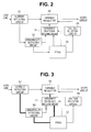
- Fig. 2 is a circuit diagram showing an example of a specific configuration of main parts in the present embodiment.
- the example of Fig. 2 shows an example of a specific configuration of the protection circuit PR1 (PR2) of Fig. 1 in which the protection processing sections PRa, PRb are configured, and shows an example of a circuit which detects an overcurrent and provides protection.
- PR1 PR2
- PRb protection processing sections PRa, PRb
- Fig. 2 shows an example where the power generating sections P1 to P3 of Fig. 1 are configured by a current detecting circuit 31, a variable regulator 32 and a voltage selecting circuit 36. Further, a field programmable gate array (hereinafter referred to as an FPGA) 35 of Fig. 2 can realize a function of the operation controlling section 11 of Fig. 1 . Note that, as for only the FPGA 35 among the components of Fig. 2 , a device common to all the power generating sections and protection circuits can be used.
- FPGA field programmable gate array
- the FPGA 35 which is the operation controlling section 11, is supplied with power supply control parameters from the ID judging section 14 (not shown) and outputs a control signal for selecting voltage which the variable regulator 32 is caused to generate, to the voltage selecting circuit 36 based on the power supply control parameters.
- the voltage selecting circuit 36 controls the variable regulator 32 to generate power supply voltage corresponding to the instruction by the FPGA 35.
- a load current detection result is inputted to the variable regulator 32 from the current detecting circuit 31.
- An output current of the variable regulator 32 is controlled so that a load current from the current detecting circuit 31 corresponds to a predetermined target value specified by the FPGA 35.
- power based on an instruction of the FPGA 35 is generated from the variable regulator 32.
- the protection circuits PR1, PR2, ... of Fig. 1 are configured by an abnormality detecting circuit 33, an overcurrent protection switching circuit 34 and the FPGA 35.
- the abnormality detecting circuit 33 is given an output of the current detecting circuit 31, judges whether an abnormality has occurred in a load current or not, and outputs a judgment result to the overcurrent protection switching circuit 34 and the FPGA 35.
- the FPGA 35 is adapted to be capable of, when a judgment result indicating an abnormality in the load current is inputted from the abnormality detecting circuit 33, outputting a shutdown instruction signal for shutting down the variable regulator 32 to the overcurrent protection switching circuit 34.
- the judgment result of the abnormality detecting circuit 33 and the shutdown instruction signal from the FPGA 35 can be inputted to the overcurrent protection switching circuit 34.
- the FPGA 35 is adapted to, when the judgment result indicating an abnormality in a load current is inputted from the abnormality detecting circuit 33, output a switching signal for causing one of the two inputs to be selectively supplied to a control end of the variable regulator 32, to the overcurrent protection switching circuit 34 based on the power supply control parameters from the ID judging section 14.
- the variable regulator 32 is adapted to, when the shutdown instruction signal is inputted to the control end by the overcurrent protection switching circuit 34, shut down immediately and stop an operation. Further, the variable regulator 32 is adapted to, when the judgment result indicating an abnormality from the abnormality detecting circuit 33 is inputted to the control end by the overcurrent protection switching circuit 34, stop output and resume output when input of the judgment result indicating the abnormality stops. That is, by switching between signals to be given to the control end of the variable regulator 32, functions of both of the protection processing sections PRa, PRb are realized by the abnormality detecting circuit 33, the overcurrent protection switching circuit 34 and the FPGA 35.
- FIGS. 3 and 4 are illustration diagrams for illustrating control in the A and B protection modes, respectively. Note that, in Figs. 3 and 4 , a signal flow is shown by thick lines, and it is indicated by ⁇ marks that a signal is not transmitted.
- the A protection mode is a protection mode designed so that shutdown immediately works when an abnormality is detected
- the B protection mode is a protection mode designed so that voltage drops without shutdown when an abnormality is detected.
- the A protection mode is set for power supply to such a scope circuit that there is a possibility of causing heat generation at a distal end or the like of an endoscope insertion portion, for example, the image pickup device.
- the B protection mode is set for such a scope circuit.
- the reading section 12 of the processor 10 reads scope IDs from the memory 24 and outputs the scope IDs to the ID judging section 14.
- the ID judging section 14 reads power supply control parameters corresponding to the scope IDs from the data storing section 13 and outputs the power supply control parameters to the FPGA 35 (the operation controlling section 11).
- the FPGA 35 can grasp kinds of power to be generated and protection modes for the respective scope circuits 21 to 23 of the endoscope 20 by the power supply control parameters.
- the abnormality detecting circuit 33 detects the abnormality by an output of the current detecting circuit 31 of the power generating section P1, and outputs a judgment result indicating the abnormality to the FPGA 35 and the overcurrent protection switching circuit 34.
- Power is supplied to the scope circuit 21 in the A protection mode, and the FPGA 35 generates a shutdown instruction signal and causes the overcurrent protection switching circuit 34 to select the output of the FPGA 35 according to the judgment result indicating the abnormality from the abnormality detecting circuit 33.
- a shutdown instruction signal from the FPGA 35 is supplied to the control end of the variable regulator 32 via the overcurrent protection switching circuit 34. Thereby, the variable regulator 32 stops output. Thus, immediately after generation of the overcurrent, shutdown is immediately performed, and power supply to the scope circuit 21 stops.
- the abnormality detecting circuit 33 detects the abnormality by an output of the current detecting circuit 31 of the power generating section P2, and outputs a judgment result indicating the abnormality to the FPGA 35 and the overcurrent protection switching circuit 34.
- the FPGA 35 neither accepts the judgment result of the abnormality detecting circuit 33 nor generates a shutdown instruction signal according to the judgment result indicating the abnormality from the abnormality detecting circuit 33. Further, the FPGA 35 causes the overcurrent protection switching circuit 34 to select the output of the abnormality detecting circuit 33.
- the thick lines in Fig. 4 show such a signal flow.
- a judgment result indicating an abnormality from the abnormality detecting circuit 33 is supplied to the control end of the variable regulator 32 via the overcurrent protection switching circuit 34.
- the variable regulator 32 stops an output.
- a current of a load line suddenly decreases.
- the judgment result indicating the abnormality is not outputted from the abnormality detecting circuit 33, and the variable regulator 32 resumes output.
- the load current shows an abnormal value again by power supply from the power generating section P2.
- the present embodiment by providing a plurality of protection processing sections for each power generating section, it becomes possible to supply power in a plurality of protection modes, and it becomes possible to acquire scope IDs and select a protection mode for each power supply based on the scope IDs. Thereby, even in a case of supplying power to a plurality kinds of endoscopes, it is possible to perform power supply corresponding to each scope circuit with a relatively small number of power generating sections and protection circuits and reduce a size of the apparatus.
- Fig. 5 is a schematic diagram showing a second embodiment of the present invention.
- the present embodiment shows another example of the protection mode.
- same components as those in Fig. 1 are given same reference numerals, and description thereof will be omitted.
- a processor 50 of Fig. 5 is provided with all the components of the processor 10 of Fig. 10, power generating sections, protection circuits and the like other than parts related to a protection processing section PRc3 which provides protection in a C protection mode are not shown. Note that description will be made on an assumption that the C protection mode is, for example, a protection mode for causing the driving power source and the driving circuit for the image pickup device to stop when an abnormality is detected.
- An endoscope 40 can be detachably mounted on the processor 50.
- An image pickup device 41 is arranged at a distal end of an insertion portion of the endoscope 40.
- the processor 50 has an image pickup device driving circuit 56 which supplies a drive signal to the image pickup device 41, and a power generating section P3 which supplies power to both of the image pickup device driving circuit 56 and the image pickup device 41.
- a master clock is inputted to the processor 50, and a timing generator (hereinafter referred to as a TG) 55 generates a timing signal for controlling each section based on the master clock.
- the image pickup device driving circuit 56 operates by being supplied with power from the power generating section P3 and generates a drive signal for driving the image pickup device 41 based on a timing signal from the TG 55.
- An image pickup output from the image pickup device 41 is supplied to an amplifier 51.
- the amplifier 51 amplifies the image pickup output and outputs it to a CDS circuit 52.
- the CDS circuit 52 performs CDS (correlated double sampling) processing for the image pickup output.
- the output from the CDS circuit 52 is given to an A/D converter 53, and the A/D converter 53 converts the image pickup output to a digital signal and outputs the digital signal to a signal processing section 54.
- the signal processing section 54 performs predetermined signal processing for the image pickup output and generates a video signal based on the image pickup output. By giving the video signal to a monitor not shown, an endoscopic image is displayed on a display screen of the monitor.
- the image pickup output from the image pickup device 41 is transmitted to the processor 50 via a scope cable 42 inserted in the endoscope 40.
- a scope cable 42 inserted in the endoscope 40.
- phase fluctuation of the image pickup output is large. Therefore, it is necessary to use a reference signal synchronized with the image pickup output in the signal processing in the signal processing section 54.
- a PLL circuit 57 is given the image pickup output and generates such a reference signal.
- a phase comparator 58 of the PLL circuit 57 determines a phase difference between the image pickup output and an output of a voltage controlled crystal oscillator (hereinafter referred to as a VCXO) 60 and outputs the phase difference to the VCXO 60 via an LPF 59.
- the VCXO 60 outputs a reference signal while changing an oscillation frequency so that the phase difference from the phase comparator 58 becomes 0.
- the reference signal synchronized with the image pickup output is generated by the PLL circuit 57 and given to the signal processing section 54. Thus, it becomes possible to perform signal processing using the reference signal synchronized with the image pickup output in the signal processing section 54.
- the protection processing section PRc3 configured with a lock detecting section 61 and a time period detecting section 62 are provided in order to enable protection in the C protection mode.
- an output of the LPF 59 becomes a predetermined constant voltage.
- the lock detecting section 61 is given an output of the LPF 59 and can judge whether the PLL circuit 57 is in a locked state or not. A judgment result of the lock detecting section 61 is supplied to the time period detecting section 62.
- the time period detecting section 62 detects a time period required until the PLL circuit 57 establishes a lock, by the output of the lock detecting section 61. If the PLL circuit 57 has not been in the locked state for a predetermined time period or more, the time period detecting section 62 judges that an abnormality has occurred in a system and generates a shutdown instruction signal.
- the shutdown instruction signal from the time period detecting section 62 of the protection processing section PRc3 is supplied to the power generating section P3 via a switch PRS.
- the switch PRS is adapted to be controlled by the operation controlling section 11.
- a memory not shown which stores scope IDs is arranged in the endoscope 40.
- the reading section 12 (see Fig. 1 ) of the processor 50 reading scope IDs from the memory of the endoscope 40, power supply control parameters corresponding to the endoscope 40 are given to the operation controlling section 11 similar as in the first embodiment.
- the operation controlling section 11 performs control so that power is supplied to the image pickup device 41 in the C protection mode.
- the operation controlling section 11 is adapted to switch on the switch PRS if the protection mode is the C protection mode and switch off the switch PRS if the mode is a mode other than the C protection mode.
- the power generating section P3 is adapted to, when a shutdown instruction signal is given from the protection processing section PRc3, shut down and stop output.
- the reading section 12 of the processor 50 reads scope IDs from the endoscope 40.
- Power supply control parameters based on the scope IDs are supplied to the operation controlling section 11.
- the operation controlling section 11 can grasp a kind of power to be generated and a protection mode for the image pickup device 41 of the endoscope 40 by the power supply control parameters. Note that description will be made on an assumption that a protection mode for power supply to the image pickup device 41 is the C protection mode for causing power supply and supply of a driving signal to the image pickup device 41 to stop when an abnormality is detected.
- the power generating section P3 outputs generated power to the image pickup device 41 and the image pickup device driving circuit 56.
- the image pickup device driving circuit 56 generates a drive signal based on a timing signal from the TG 55 and supplies the drive signal to the image pickup device 41.
- the image pickup device 41 performs image pickup.
- An image pickup output from the image pickup device 41 is supplied to the processor 50 via the scope cable 42.
- the image pickup output is amplified by the amplifier 51, CDS-processed by the CDS circuit 52, converted to a digital signal by the A/D converter 53 and supplied to the signal processing section 54.
- the image pickup output from the image pickup device 41 is supplied to the PLL circuit 57.
- the PLL circuit 57 generates a reference signal synchronized with the image pickup output and outputs the reference signal to the signal processing section 54.
- the signal processing section 54 performs various kinds of signal processing for the image pickup output using the reference signal from the PLL circuit 57 to generate a video signal and output the video signal.
- the lock detecting section 61 has detected the locked state by an output of the LPF 59 and outputs a detection result showing that the locked state has not been established to the time period detecting section 62.
- the time period detecting section 62 judges that an abnormality has occurred in the system and generates a shutdown instruction signal.
- the operation controlling section 11 switched on the switch PRS for the power generating section P3 in order to provide protection by the C protection mode.
- the shutdown instruction signal from the time period detecting section 62 is supplied to the power generating section P3 via the switch PRS.
- the power generating section P3 stops output.
- the image pickup device driving circuit 56 also stops its operation, and supply of a drive signal to the image pickup device 41 also stops. In this way, protection by the C protection mode is provided.
- Fig. 6 is a flowchart showing a third embodiment of the present invention.
- a hardware configuration of the present embodiment is similar to that of the first embodiment.
- the present embodiment is different from the first embodiment only in control by the operation controlling section.
- a protection mode for each power generating section is fixedly decided based on a scope ID.
- the protection mode of each power generating section can be changed according to elapse of a predetermined time period or a course of a predetermined sequence.
- an inrush current occurs when operations of the power generating sections P start.
- a control loop for controlling the variable regulator 32 from the current detecting circuit 31 via the abnormality detecting circuit 33 and the overcurrent protection switching circuit 34 shown in Fig. 2 that is, a constant current control loop is effective. Therefore, by performing overcurrent protection in the B protection mode shown in Fig. 4 , the inrush current can be prevented.
- overcurrent protection in the A protection mode in Fig. 3 for immediately performing shutdown may be preferable.
- the operation controlling section 11 is adapted to be capable of, even in a case of power supply to a circuit required to be immediate shut down, performing power supply in the B protection mode until a predetermined time period elapses after start of an operation and switching to power supply in the A protection mode when the predetermined time period has elapsed. Further, the operation controlling section 11 may detect a course of a predetermined sequence and change the protection mode. For example, at a time of power supply to the image pickup device, the operation controlling section 11 may detect whether a video signal based on an image pickup output is to be outputted or not, perform power supply in the B protection mode until the video signal is outputted, and, when the video signal is outputted, switch to power supply in the A protection mode afterwards.
- Fig. 6 shows an example of switching the protection mode according to elapse of a time period.
- the operation controlling section 11 acquires power supply control parameters corresponding to scope IDs at step S1 in Fig. 6 .
- the operation controlling section 11 causes the protection circuits PR to select the protection processing sections PRb in the B protection mode and instructs the power generating sections P to generate power.
- the power generating sections P generate power and supply the power to target circuits.
- the abnormality detecting circuit 33 detects an overcurrent. Then, the power generating sections P is constant-current-controlled by the protection processing sections PRb, and generation of the inrush current is suppressed.
- the operation controlling section 11 judges whether or not the control target circuits are to be overcurrent-protected in the A protection mode in the end, by the power supply control parameters (step S3). If the control target circuits are required to be overcurrent-protected in the A protection mode, the operation controlling section 11 judges at step S4 whether a predetermined time period has elapsed or not. If the predetermined time period has elapsed, the operation controlling section 11 causes the protection circuits PR to select the protection processing sections PRa in the A protection mode and changes an overcurrent-protection mode to the A protection mode at step S5.
- the protection mode it is possible to change the protection mode according to elapse of a time period or a course of a predetermined sequence. Thereby, for example, it is also possible to omit an inrush current preventing circuit.
- Fig. 7 is a flowchart showing a fourth embodiment of the present invention.
- a hardware configuration of the present embodiment is similar to that of the first embodiment.
- the present embodiment is different from the first embodiment only in control by the operation controlling section.
- each power generating section is driven in accordance with a predetermined sequence, and each power generating section is caused to sequentially operate while it is judged whether each power generating section is normally operating or not.
- the operation controlling section 11 acquires power supply control parameters corresponding to scope IDs.
- the operation controlling section 11 judges order of causing the respective power generating sections P1, P2, ... to be activated and start power supply (a power supply sequence), by the power supply control parameters (step S10).
- the operation controlling section 11 causes a first power generating section P in the power supply sequence to start a power generating operation (step S11).
- the operation controlling section 11 is in a waiting state until power is generated from the power generating section P which has been caused to start the power generating operation.
- power supply control is not managed by a time period but managed only by the power supply sequence.
- the operation controlling section 11 judges that power supply is normally performed if voltage of the output is equal to or larger than a predetermined threshold voltage, for example, (rated voltage ⁇ 0.8), and judges that power supply is not normally performed if the predetermined threshold voltage is not reached.
- a predetermined threshold voltage for example, (rated voltage ⁇ 0.8)
- the operation controlling section 11 is configured with an FPGA, it is possible for the operation controlling section 11 to detect the output voltage of the power generating section P by converting the output of the power generating section P to a digital signal and supplying the digital signal to the operation controlling section 11.
- the operation controlling section 11 advances the process from step S 13 to step S17, stops the operation of the power generating section P and ends the process. If judging that power supply is normally performed, the operation controlling section 11 advances the process from step S 13 to step S 14 and causes power to be supplied from the power generating sections P to target circuits.
- step S 15 the operation controlling section 11 judges whether a power generating operation of a last power generating section P of the power supply sequence has ended or not. If the power generating operation has not ended, the operation controlling section 11 returns the process to step S12 and causes a power generating operation of a next power generating section P of the power supply sequence to start.
- the operation controlling section 11 advances the process from step S15 to S16, and judges whether or not all power supply is normally performed in the end. For example, if the operation controlling section 11 detects that voltage of an output of any one power generating section P is equal to or larger than "rated voltage ⁇ 1.2, the operation controlling section 11 judges that power supply is not normally performed, and causes all the power supply to be stopped at step S 17.
- order of activating the respective power generating sections is controlled in accordance with a power supply sequence corresponding to an endoscope connected to the processor 10. While confirming that each piece of power has been normally generated, the operation controlling section 11 activates a next power generating section in accordance with the power supply sequence. Thereby, normal power supply voltage is supplied to each target circuit in accordance with the power supply sequence, and a normal operation can be expected in the endoscope.
Landscapes
- Health & Medical Sciences (AREA)
- Life Sciences & Earth Sciences (AREA)
- Surgery (AREA)
- Physics & Mathematics (AREA)
- Engineering & Computer Science (AREA)
- Optics & Photonics (AREA)
- Biomedical Technology (AREA)
- Veterinary Medicine (AREA)
- Biophysics (AREA)
- Pathology (AREA)
- Radiology & Medical Imaging (AREA)
- Nuclear Medicine, Radiotherapy & Molecular Imaging (AREA)
- Public Health (AREA)
- Heart & Thoracic Surgery (AREA)
- Medical Informatics (AREA)
- Molecular Biology (AREA)
- Animal Behavior & Ethology (AREA)
- General Health & Medical Sciences (AREA)
- Signal Processing (AREA)
- Astronomy & Astrophysics (AREA)
- General Physics & Mathematics (AREA)
- Multimedia (AREA)
- Endoscopes (AREA)
- Instruments For Viewing The Inside Of Hollow Bodies (AREA)
- Closed-Circuit Television Systems (AREA)
Applications Claiming Priority (2)
| Application Number | Priority Date | Filing Date | Title |
|---|---|---|---|
| JP2013166333 | 2013-08-09 | ||
| PCT/JP2014/069947 WO2015019903A1 (ja) | 2013-08-09 | 2014-07-29 | 内視鏡装置 |
Publications (2)
| Publication Number | Publication Date |
|---|---|
| EP2954834A1 true EP2954834A1 (de) | 2015-12-16 |
| EP2954834A4 EP2954834A4 (de) | 2016-11-30 |
Family
ID=52461241
Family Applications (1)
| Application Number | Title | Priority Date | Filing Date |
|---|---|---|---|
| EP14835139.8A Withdrawn EP2954834A4 (de) | 2013-08-09 | 2014-07-29 | Endoskopische vorrichtung |
Country Status (5)
| Country | Link |
|---|---|
| US (1) | US9610004B2 (de) |
| EP (1) | EP2954834A4 (de) |
| JP (1) | JP5767422B2 (de) |
| CN (1) | CN105188510B (de) |
| WO (1) | WO2015019903A1 (de) |
Families Citing this family (14)
| Publication number | Priority date | Publication date | Assignee | Title |
|---|---|---|---|---|
| JP6348854B2 (ja) * | 2015-02-03 | 2018-06-27 | 富士フイルム株式会社 | 内視鏡用プロセッサ装置、内視鏡システム及び内視鏡システムの非接触給電方法 |
| JP6353810B2 (ja) * | 2015-04-24 | 2018-07-04 | 富士フイルム株式会社 | 内視鏡システム |
| CN107405059B (zh) * | 2015-06-26 | 2019-05-28 | 奥林巴斯株式会社 | 内窥镜电源供给系统 |
| JP6219004B1 (ja) * | 2016-05-24 | 2017-10-25 | オリンパス株式会社 | 内視鏡用カメラコントロールユニット |
| WO2017203829A1 (ja) * | 2016-05-24 | 2017-11-30 | オリンパス株式会社 | 内視鏡用カメラコントロールユニット及び内視鏡システム |
| CN109310281B (zh) * | 2016-08-02 | 2021-03-12 | 奥林巴斯株式会社 | 内窥镜系统和信号处理装置 |
| WO2018092399A1 (ja) * | 2016-11-17 | 2018-05-24 | オリンパス株式会社 | 内視鏡装置 |
| CN110891470B (zh) * | 2017-05-18 | 2022-09-23 | 奥林巴斯株式会社 | 内窥镜系统、内窥镜以及控制装置 |
| WO2019008895A1 (ja) * | 2017-07-07 | 2019-01-10 | オリンパス株式会社 | 自走式内視鏡装置及びその制御装置 |
| JP7007493B2 (ja) * | 2018-10-03 | 2022-01-24 | オリンパス株式会社 | 内視鏡用電源装置 |
| WO2021077240A1 (zh) * | 2019-10-21 | 2021-04-29 | 新儿护科技医疗器材股份有限公司 | 智能侦测脏器的内视镜主机及内视镜装置 |
| US11963683B2 (en) * | 2020-10-02 | 2024-04-23 | Cilag Gmbh International | Method for operating tiered operation modes in a surgical system |
| JP7818374B2 (ja) * | 2021-10-14 | 2026-02-20 | Hoya株式会社 | 内視鏡用プロセッサ、及び内視鏡システム |
| CN119112076B (zh) * | 2024-10-22 | 2025-06-24 | 深圳市视诺祺电子科技有限公司 | 一种基于智能镜种识别的内窥镜检测系统 |
Family Cites Families (16)
| Publication number | Priority date | Publication date | Assignee | Title |
|---|---|---|---|---|
| US5400267A (en) * | 1992-12-08 | 1995-03-21 | Hemostatix Corporation | Local in-device memory feature for electrically powered medical equipment |
| US5896166A (en) * | 1993-06-02 | 1999-04-20 | Envision Medical Corporation | Remote CCD video camera with non-volatile digital memory |
| JP2687276B2 (ja) * | 1993-12-28 | 1997-12-08 | オリンパス光学工業株式会社 | 電子内視鏡装置 |
| US6638212B1 (en) * | 1999-07-27 | 2003-10-28 | Olympus Optical | Endoscope system having storage part of endoscope-related-data provided in endoscope |
| JP4610713B2 (ja) * | 2000-10-13 | 2011-01-12 | オリンパス株式会社 | 内視鏡装置 |
| JP4689206B2 (ja) * | 2004-07-26 | 2011-05-25 | オリンパス株式会社 | 電子内視鏡システム |
| JP4804062B2 (ja) * | 2005-07-29 | 2011-10-26 | オリンパス株式会社 | 内視鏡システム |
| JP4814717B2 (ja) * | 2006-07-28 | 2011-11-16 | Hoya株式会社 | 電子内視鏡、及び、電子内視鏡システム |
| JP4954659B2 (ja) * | 2006-10-10 | 2012-06-20 | 株式会社リコー | 撮像装置 |
| JP2009189529A (ja) * | 2008-02-14 | 2009-08-27 | Fujinon Corp | 内視鏡用プロセッサ装置 |
| JP2010088656A (ja) | 2008-10-08 | 2010-04-22 | Fujifilm Corp | 内視鏡用プロセッサ装置、内視鏡用プロセッサ装置の電源電圧供給方法、並びに内視鏡システム |
| JP5622460B2 (ja) * | 2010-07-05 | 2014-11-12 | オリンパス株式会社 | 内視鏡装置 |
| WO2012008259A1 (ja) * | 2010-07-12 | 2012-01-19 | オリンパスメディカルシステムズ株式会社 | 内視鏡画像処理装置及び内視鏡システム |
| CN103384492B (zh) * | 2011-09-22 | 2015-12-02 | 奥林巴斯株式会社 | 内窥镜 |
| JP6005989B2 (ja) * | 2012-05-16 | 2016-10-12 | オリンパス株式会社 | 内視鏡装置 |
| JP6258751B2 (ja) * | 2014-03-31 | 2018-01-10 | Hoya株式会社 | 負荷電圧制御装置、電子内視鏡および電子内視鏡システム |
-
2014
- 2014-07-29 WO PCT/JP2014/069947 patent/WO2015019903A1/ja not_active Ceased
- 2014-07-29 EP EP14835139.8A patent/EP2954834A4/de not_active Withdrawn
- 2014-07-29 JP JP2015505371A patent/JP5767422B2/ja not_active Expired - Fee Related
- 2014-07-29 CN CN201480013087.4A patent/CN105188510B/zh active Active
-
2015
- 2015-09-09 US US14/849,081 patent/US9610004B2/en not_active Expired - Fee Related
Also Published As
| Publication number | Publication date |
|---|---|
| CN105188510B (zh) | 2017-10-31 |
| US9610004B2 (en) | 2017-04-04 |
| US20150374204A1 (en) | 2015-12-31 |
| JPWO2015019903A1 (ja) | 2017-03-02 |
| CN105188510A (zh) | 2015-12-23 |
| JP5767422B2 (ja) | 2015-08-19 |
| EP2954834A4 (de) | 2016-11-30 |
| WO2015019903A1 (ja) | 2015-02-12 |
Similar Documents
| Publication | Publication Date | Title |
|---|---|---|
| US9610004B2 (en) | Endoscope apparatus with power generating section and protection circuit | |
| JP5037731B2 (ja) | 内視鏡画像処理装置及び内視鏡システム | |
| JP6495565B1 (ja) | 医療表示装置 | |
| US20190082941A1 (en) | Camera control unit for endoscope and endoscope system | |
| US8622895B2 (en) | Electric bending endoscope | |
| EP2062524A1 (de) | Endoskopvorrichtung | |
| CN105705076A (zh) | 电子内窥镜系统、电子内窥镜、电源装置、电子内窥镜系统的动作方法 | |
| CN110891470A (zh) | 内窥镜系统 | |
| EP2090220A1 (de) | Prozessor für Endoskope | |
| EP3222200A1 (de) | Endoskopievorrichtung | |
| CN105899124B (zh) | 内窥镜装置 | |
| JP2011200482A (ja) | リセット機能を備えた電源回路 | |
| JP6265815B2 (ja) | 電子内視鏡システム | |
| JP2010206902A (ja) | 複数の巻線を備えたモータを駆動するモータ駆動システム | |
| JP6523593B2 (ja) | 撮像装置 | |
| US20190102881A1 (en) | Endoscope apparatus and camera control unit | |
| JP2016214571A (ja) | 内視鏡システム | |
| JP5361296B2 (ja) | 内視鏡装置 | |
| JP6470114B2 (ja) | 制御システム | |
| JP2016202203A (ja) | 電源管理システム | |
| JP2006346357A (ja) | 内視鏡装置 | |
| JP2008173398A (ja) | 医療機器制御システム | |
| JP2017205150A (ja) | 医療画像記録装置 | |
| JP2018198854A (ja) | 内視鏡システム | |
| JPWO2017203829A1 (ja) | 内視鏡用カメラコントロールユニット |
Legal Events
| Date | Code | Title | Description |
|---|---|---|---|
| PUAI | Public reference made under article 153(3) epc to a published international application that has entered the european phase |
Free format text: ORIGINAL CODE: 0009012 |
|
| 17P | Request for examination filed |
Effective date: 20150908 |
|
| AK | Designated contracting states |
Kind code of ref document: A1 Designated state(s): AL AT BE BG CH CY CZ DE DK EE ES FI FR GB GR HR HU IE IS IT LI LT LU LV MC MK MT NL NO PL PT RO RS SE SI SK SM TR |
|
| AX | Request for extension of the european patent |
Extension state: BA ME |
|
| RAP1 | Party data changed (applicant data changed or rights of an application transferred) |
Owner name: OLYMPUS CORPORATION |
|
| RAP1 | Party data changed (applicant data changed or rights of an application transferred) |
Owner name: OLYMPUS CORPORATION |
|
| RIN1 | Information on inventor provided before grant (corrected) |
Inventor name: TABUCHI, KOICHIRO Inventor name: NEMOTO, MITSUTAKA Inventor name: SHINANO, HIDEKAZU Inventor name: ONO, MAKOTO |
|
| DAX | Request for extension of the european patent (deleted) | ||
| A4 | Supplementary search report drawn up and despatched |
Effective date: 20161103 |
|
| RIC1 | Information provided on ipc code assigned before grant |
Ipc: A61B 1/04 20060101AFI20161027BHEP Ipc: G02B 23/24 20060101ALI20161027BHEP Ipc: H04N 7/18 20060101ALI20161027BHEP |
|
| STAA | Information on the status of an ep patent application or granted ep patent |
Free format text: STATUS: REQUEST FOR EXAMINATION WAS MADE |
|
| STAA | Information on the status of an ep patent application or granted ep patent |
Free format text: STATUS: THE APPLICATION IS DEEMED TO BE WITHDRAWN |
|
| 18D | Application deemed to be withdrawn |
Effective date: 20190201 |