EP2954861B1 - Système de nettoyage pour le retraitement de dispositifs médicaux - Google Patents
Système de nettoyage pour le retraitement de dispositifs médicaux Download PDFInfo
- Publication number
- EP2954861B1 EP2954861B1 EP15160513.6A EP15160513A EP2954861B1 EP 2954861 B1 EP2954861 B1 EP 2954861B1 EP 15160513 A EP15160513 A EP 15160513A EP 2954861 B1 EP2954861 B1 EP 2954861B1
- Authority
- EP
- European Patent Office
- Prior art keywords
- cleaning
- medical device
- receiving portion
- assembly
- fixture
- Prior art date
- Legal status (The legal status is an assumption and is not a legal conclusion. Google has not performed a legal analysis and makes no representation as to the accuracy of the status listed.)
- Not-in-force
Links
Images




Classifications
-
- A—HUMAN NECESSITIES
- A61—MEDICAL OR VETERINARY SCIENCE; HYGIENE
- A61B—DIAGNOSIS; SURGERY; IDENTIFICATION
- A61B90/00—Instruments, implements or accessories specially adapted for surgery or diagnosis and not covered by any of the groups A61B1/00 - A61B50/00, e.g. for luxation treatment or for protecting wound edges
- A61B90/70—Cleaning devices specially adapted for surgical instruments
-
- A—HUMAN NECESSITIES
- A61—MEDICAL OR VETERINARY SCIENCE; HYGIENE
- A61B—DIAGNOSIS; SURGERY; IDENTIFICATION
- A61B1/00—Instruments for performing medical examinations of the interior of cavities or tubes of the body by visual or photographical inspection, e.g. endoscopes; Illuminating arrangements therefor
- A61B1/12—Instruments for performing medical examinations of the interior of cavities or tubes of the body by visual or photographical inspection, e.g. endoscopes; Illuminating arrangements therefor with cooling or rinsing arrangements
- A61B1/121—Instruments for performing medical examinations of the interior of cavities or tubes of the body by visual or photographical inspection, e.g. endoscopes; Illuminating arrangements therefor with cooling or rinsing arrangements provided with means for cleaning post-use
-
- A—HUMAN NECESSITIES
- A61—MEDICAL OR VETERINARY SCIENCE; HYGIENE
- A61B—DIAGNOSIS; SURGERY; IDENTIFICATION
- A61B1/00—Instruments for performing medical examinations of the interior of cavities or tubes of the body by visual or photographical inspection, e.g. endoscopes; Illuminating arrangements therefor
- A61B1/12—Instruments for performing medical examinations of the interior of cavities or tubes of the body by visual or photographical inspection, e.g. endoscopes; Illuminating arrangements therefor with cooling or rinsing arrangements
- A61B1/121—Instruments for performing medical examinations of the interior of cavities or tubes of the body by visual or photographical inspection, e.g. endoscopes; Illuminating arrangements therefor with cooling or rinsing arrangements provided with means for cleaning post-use
- A61B1/123—Instruments for performing medical examinations of the interior of cavities or tubes of the body by visual or photographical inspection, e.g. endoscopes; Illuminating arrangements therefor with cooling or rinsing arrangements provided with means for cleaning post-use using washing machines
-
- A—HUMAN NECESSITIES
- A61—MEDICAL OR VETERINARY SCIENCE; HYGIENE
- A61B—DIAGNOSIS; SURGERY; IDENTIFICATION
- A61B17/00—Surgical instruments, devices or methods
- A61B17/28—Surgical forceps
- A61B17/29—Forceps for use in minimally invasive surgery
-
- B—PERFORMING OPERATIONS; TRANSPORTING
- B08—CLEANING
- B08B—CLEANING IN GENERAL; PREVENTION OF FOULING IN GENERAL
- B08B3/00—Cleaning by methods involving the use or presence of liquid or steam
- B08B3/04—Cleaning involving contact with liquid
-
- A—HUMAN NECESSITIES
- A61—MEDICAL OR VETERINARY SCIENCE; HYGIENE
- A61B—DIAGNOSIS; SURGERY; IDENTIFICATION
- A61B18/00—Surgical instruments, devices or methods for transferring non-mechanical forms of energy to or from the body
- A61B18/04—Surgical instruments, devices or methods for transferring non-mechanical forms of energy to or from the body by heating
- A61B18/12—Surgical instruments, devices or methods for transferring non-mechanical forms of energy to or from the body by heating by passing a current through the tissue to be heated, e.g. high-frequency current
- A61B18/14—Probes or electrodes therefor
- A61B18/1442—Probes having pivoting end effectors, e.g. forceps
- A61B18/1445—Probes having pivoting end effectors, e.g. forceps at the distal end of a shaft, e.g. forceps or scissors at the end of a rigid rod
Definitions
- the present disclosure relates to reprocessing medical devices, and more particularly, to systems and methods for reprocessing medical devices.
- Cleaning of medical devices is a known challenge in the field of medical device reprocessing.
- medical devices usually require substantial disassembly prior to manual or mechanical cleaning. Such disassembly is undesirable because it is a time consuming process, increases the probability of damage, and decreases the fatigue life of the device parts.
- Another challenge in reprocessing is adequate cleaning. While reprocessing systems typically rely on delivering chemicals and kinetic energy, all surfaces and components of the devices are typically cleaned with the same energy in the same fashion. This is problematic because it can result in inadequate cleaning of the more heavily contaminated areas of the device.
- WO2012148266 relates to an operating device for operating a medical instrument in a cleaning and disinfection machine provided with a mounting part for mounting a medical instrument, wherein the instrument is provided with an operating element with which a moveable instrument part can be moved, an activation member, during use provided near the operating element, such as on the mounting part, facing towards the instrument and adapted to engage the operating element, wherein the activation member during use is driveably connected to a drive, in such a way that the moveable instrument part is moveable by the drive.
- a cleaning fixture for cleaning a medical device in accordance with claim 1 is provided. Preferred embodiments of this cleaning fixture are claimed in claims 2-6.
- the cleaning fixture includes a shaft receiving portion configured to receive a shaft and end effector assembly of the medical device, the shaft receiving portion including at least one nozzle disposed towards a distal end of the shaft receiving portion such that the at least one nozzle is positioned adjacent the end effector assembly of the medical device upon receipt of the shaft and end effector assembly of the medical device within the shaft receiving portion; and a handle receiving portion configured to receive the housing and handle of the medical device, the handle receiving portion releasably securable with the shaft receiving portion to enclose the medical device therein, the handle receiving portion including at least one lever activation assembly positioned adjacent the handle and operable to selectively actuate the handle to manipulate the end effector assembly.
- the lever activation assembly includes a nozzle, an actuator, and a lever.
- the lever activation assembly is coupled to a valve system configured to supply a fluid, the lever activation assembly configured to actuate simultaneously and/or independently when the fluid is supplied to the lever activation assembly from the valve system.
- the lever activation assembly comprises a mechanism for mechanically or hydraulically urging movement of the handle.
- the mechanism may comprise a motor.
- the handle is movable for moving jaw members of the end effector assembly between an open position and a clamping position.
- the at least one nozzle is disposed on the circumference of the shaft receiving portion.
- the shaft receiving portion is an elongate muzzle defining a longitudinal axis.
- the shaft receiving portion includes a keying member.
- the keying member is tailored to complement a portion of the medical device such that the medical device is securely seated within the handle receiving portion.
- the at least one nozzle comprises nozzles that are disposed annularly about the shaft receiving portion to direct the flow of fluid from the nozzles radially inwardly into a lumen of the shaft receiving portion towards a longitudinal axis of the shaft of the medical device, and disposed about the end effector assembly and/or to withdraw fluids therefrom.
- the at least one nozzle comprises a nozzle disposed at a distal end of the shaft receiving portion and defines an inlet that provides access to an interior lumen of the shaft receiving portion, wherein the nozzle is configured to direct the flow of fluid from the nozzle coaxially along a longitudinal axis of the shaft of the medical device in a proximal direction towards the end effector assembly and/or therefrom.
- an automated system for cleaning a medical device as claimed in claim 7 is provided.
- Preferred embodiments of this system are claimed in claims 8-10.
- the system includes the cleaning fixture described above; a dosage device configured to provide a cleaning mixture; a valve system configured to selectively provide the cleaning mixture to the at least one nozzle of the cleaning fixture; and a controller configured to control at least one of the dosage device, the valve system, or actuation of the lever activation assembly.
- the controller is configured to control the dosage device, the valve system, and the lever activation system.
- system further includes a fluid supply coupled to at least one of the dosage device or the valve system.
- the lever activation assembly is coupled to the valve system and is selectively actuatable in response to fluid being supplied thereto, and wherein the controller is configured to control the supply of fluid to the lever activation assembly.
- an air supply coupled to the valve assembly.
- the controller is configured to activate the air supply to supply air to the cleaning fixture, optionally through the at least one nozzle thereof, to dry the medical device.
- system further comprises a vacuum source and the controller is configured to supplying vacuum to the cleaning fixture to facilitate drying of the medical device.
- the controller is configured to control the valve assembly to supply at least one of air, water, vacuum, or the cleaning mixture.
- the controller is configured to supply the cleaning mixture and activate the lever activation assembly simultaneously and/or independently, e.g., intermittently or randomly.
- the controller is configured to activate the lever activation assembly repeatedly during a cleaning cycle in which cleaning mixture is supplied from the dosage device to an end effector of the medical device disposed in the shaft receiving portion.
- the controller is configured to execute a cleaning program comprising a cleaning stage in which the cleaning mixture is delivered to the medical device, optionally an end effector assembly of the medical device, and in which the lever activation assembly is activated, the cleaning program additionally comprising at least one of a draining stage, a drying stage and a vacuum stage.
- a drying stage an air supply may be activated.
- a vacuum source may be activated.
- one or more flushing ports may be opened and/or water is supplied to the cleaning fixture, e.g. through the at least one nozzle, without added cleaning chemicals.
- a method of reprocessing a medical device in accordance with claim 11 is provided. Preferred embodiments of this method are claimed in claims 12-15.
- the method includes, positioning a medical device within the cleaning fixture described above; supplying a cleaning mixture to the cleaning fixture; and activating the lever activation assembly of the cleaning fixture to manipulate an end effector assembly of the medical device to facilitate cleaning of the medical device with the cleaning mixture.
- supplying the cleaning mixture and activating the lever activation assembly are performed simultaneously and/or independently, e.g., intermittently or randomly.
- the method further includes controlling the supplying of the cleaning mixture and activating the lever activation assembly in accordance with a cleaning program.
- the method further includes mixing a fluid with at least one cleaning component to form the cleaning mixture prior to supplying the cleaning mixture.
- the method further includes draining the cleaning mixture from the cleaning fixture.
- the method further includes supplying air to the cleaning fixture to facilitate drying of the medical device.
- the method further includes supplying vacuum to the cleaning fixture to facilitate drying of the medical device.
- the present disclosure relates to systems and methods for reprocessing medical devices.
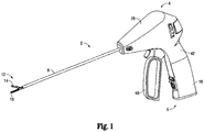
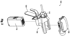
- Fig. 1 depicts a portable, battery-powered electrosurgical instrument 2 and Figs. 2-3 depict a portable, battery-powered ultrasonic surgical instrument 102.
- exemplary medical devices electrosurgical instrument 2 and ultrasonic surgical instrument 102 are detailed herein, the present disclosure is equally applicable for use in reprocessing any suitable medical devices. As such, electrosurgical instrument 2 and ultrasonic surgical instrument 102 are only summarily described herein.
- electrosurgical instrument 2 shown as an electrosurgical forceps, generally includes a housing 4, a battery assembly 18, an electrosurgical generator 28, a handle assembly 6, a shaft 8 defining a longitudinal axis, and an end effector assembly 12.
- Handle assembly 6 includes a moveable handle 40 that is movable relative to a fixed handle portion 42 for moving jaw members 14, 16 of end effector assembly 12 between an open position and a clamping position for grasping tissue therebetween.
- Generator 28 is powered by battery assembly 18 and is configured to supply electrosurgical energy to one or both of jaw members 14, 16 for electrosurgically treating tissue grasped therebetween.
- ultrasonic instrument 102 includes components similar to that of electrosurgical instrument 2 ( Fig. 1 ), namely, a housing 104, a battery assembly 118, a transducer and generator (“TAG”) assembly 130, a shaft 108, and an end effector assembly 112.
- Housing 104 is configured to releasably engage battery assembly 118 and TAG assembly 130 thereon.
- Shaft 108 extends distally from housing 104 defining a longitudinal axis.
- Shaft 108 further includes an end effector assembly 112 disposed at a distal end thereof.
- End effector assembly 112 includes a movable jaw 114 and a waveguide 116.
- a moveable handle 124 is operatively connected to housing 104 and is configured to move jaw 114 relative to waveguide 116 between an open position and a clamping position for grasping tissue therebetween.
- a distal collar 110 is coupled to housing 104 and end effector assembly 112 for selectively rotating end effector assembly 112 relative to housing 104.
- TAG assembly 130 is powered by battery assembly 118 and is configured to supply ultrasonic energy to waveguide 116 of end effector assembly 112 for ultrasonically treating tissue grasped between waveguide 116 and movable jaw 114.
- battery assemblies 18, 118, generator 28, and TAG assembly 130 are removed from their respective instruments 2, 102 prior to cleaning.
- cleaning fixture 200 a cleaning fixture provided in accordance with the present disclosure is shown generally as cleaning fixture 200.
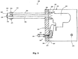
- Cleaning fixture 200 is shown housing ultrasonic surgical instrument 102 therein (see Fig. 5 ) for cleaning of ultrasonic surgical instrument 102.
- cleaning fixture 200 may similarly be configured for use with electrosurgical instrument 2 ( Fig. 1 ), or any other suitable medical device.
- electrosurgical instrument 2 Fig. 1
- a generic cleaning fixture be provided to enable cleaning of any one of a variety of different medical devices.
- Such a generic cleaning fixture may include interchangeable and/or adaptable components configured to achieve various different configurations to accommodate various different medical devices.
- cleaning fixture 200 includes a shaft receiving portion 202 and a handle receiving portion 204. Both shaft and handle receiving portions 202, 204, respectively, have a distal and a proximal end.
- Shaft receiving portion 202 includes a proximal section 206 at the proximal end thereof that is releasably secured to the distal end 207 of handle receiving portion 204 by fastening members 209.
- Fastening members 209 may include latches or any other suitable releasable fastening mechanism.
- Proximal section 206 of shaft receiving portion 202 and handle receiving portion 204, when fastened to one another, cooperate to define an enclosure for retaining housing 104 of surgical instrument 102 therein (see Fig. 5 ), as detailed below.
- shaft receiving portion 202 includes an elongate muzzle 203 extending distally from proximal section 206.
- Elongate muzzle 203 defines a longitudinal axis and includes a lumen extending longitudinally therethrough.
- the lumen of muzzle 203 has a diameter dimensioned such that end effector assembly 112 and shaft 108 may be inserted through the lumen of muzzle 203 in spaced relation relative to the inner surface of muzzle 203.
- the length of muzzle 203 is formed to be approximately the combined length of shaft 108 and end effector assembly 112 of surgical instrument 102 to fully accommodate such therein.
- Proximal section 206 of shaft receiving portion 202 is configured to be releasably secured to handle receiving portion 204, e.g., via fastening member 209. Further, proximal section 206 includes a keying member 210 that is tailored to receive distal collar 110 (or other suitable component) of surgical instrument 102 to retain surgical instrument 102 in a substantially fixed position within cleaning fixture 200. Keying member 210 is tailored to be a complementary structure to collar 110 such that keying member 210 is securely mated with collar 110.
- collar 110 generally defines star-like configuration having a plurality of radially-spaced protrusions extending therefrom and keying member 210 defines a plurality of radially-spaced recesses each configured to receive one of the protrusions.
- keying member 210 may be custom tailored (or a plurality of interchangeable keying members 210 may be provided) to complement other types of distal collars to accommodate other medical devices within cleaning fixture 200.
- Shaft receiving portion 202 of cleaning fixture 200 further includes a nozzle system 230 disposed towards the distal end 205 of shaft receiving portion 202.
- Nozzle system 230 may be operatively connected to a valve system 500 ( Fig. 6 ) by one or more lines (not explicitly shown), although any other suitable connector(s) for delivering fluid to nozzle system 230 may be provided.
- Nozzle system 230 is coupled to the outer surface of muzzle 203 and defines at least one inlet that provides access to the interior lumen of muzzle 203.
- nozzles 232, 234, 236 are disposed annularly about the circumference of muzzle 203 to direct the flow of fluid from nozzles 232, 234, 236 radially inwardly into the lumen of muzzle 203 towards the longitudinal axis of surgical instrument 102, and radially about end effector assembly 112 and/or to withdraw fluids therefrom.
- Another nozzle 238 is disposed on the closed distal end 205 of shaft receiving portion 202 and likewise defines an inlet that provides access to the interior lumen of muzzle 203.
- Nozzle 238 is configured to direct the flow of fluid from nozzle 238 coaxially along the longitudinal axis of surgical instrument 102 in a proximal direction towards end effector assembly 112 and/or therefrom.
- nozzle system 230 is described as having four nozzles 232, 234, 236, 238, this is for exemplary purposes only as it is contemplated that nozzle system 230 may include any suitable number of nozzles provided in any suitable configuration.
- shaft receiving portion 202 further includes a lever activation assembly 220 disposed on proximal section 206 thereof.
- Lever activation assembly 220 has a lever 222, an actuator, e.g., a cylinder 224, and a nozzle 226.
- Lever 222 is positioned such that, when surgical instrument 102 is disposed within cleaning fixture 200, movable handle 124 of surgical instrument 102 is straddled over lever 222.
- the actuator may be a cylinder 224 such as a hydraulic cylinder, pneumatic cylinder, other suitable cylinder, or other suitable actuator.
- Nozzle 226 is configured to be operatively connected to valve system 500 ( Fig. 6 ) by any suitable connector (not explicitly shown) to deliver fluid pressure to cylinder 224.
- valve system 500 Fig. 6
- any suitable connector not explicitly shown
- cylinder 224 When fluid is delivered from valve system 500, through nozzle 226, to cylinder 224, cylinder 224 is actuated and urges lever 222 from a first position to a second position. Such movement of lever 222, in turn, actuates moveable handle 124 to thereby manipulate end effector assembly 112 from the open position to the clamping position.
- Handle receiving portion 204 of cleaning fixture 200 is configured to receive housing 104 of the surgical instrument 102 and further includes one or more flushing ports 240.
- Each flushing port 240 is operatively connected to any suitable connector, e.g., a hose, to carry fluid from cleaning fixture 200 to a drain or other outlet (not explicitly shown).
- cleaning fixture 200 is operatively connected to a control box 300.
- control box 300 is configured to connect to a plurality of cleaning fixtures 200 to facilitate simultaneous cleaning of multiple medical devices (similar or different). However, for purposes of simplicity, control box 300 is described herein as configured for use with a single cleaning fixture 200.
- Control box 300 includes a dosage control system 400, valve system 500, an air supply 600, a vacuum source 700, and a multidirectional valve 800.
- Dosage control system 400 is coupled to a fluid supply, e.g., a water supply (not shown), for mixing with one or more chemicals, cleaning compounds, etc. stored within or input into dosage control system 400.
- a fluid supply e.g., a water supply (not shown)
- Such chemicals and cleaning compounds may include, for example, enzymatic compounds, detergents, disinfectants, etc.
- Dosage control system 400 may additionally be configured to simply provide the fluid from the fluid supply without adding any chemicals, e.g., during a flushing or rinsing stage, and may further include one or more heaters (not specifically shown) for heating the fluid and/or mixture to be supplied to a desired temperature to facilitate cleaning.
- Control box 300 further includes a CPU and memory, e.g., a RAM, that executes and stores one or more cleaning programs, respectively.
- the CPU is operatively connected to dosage system 400, valve system 500, air supply 600, vacuum source 700 and multidirectional valve 800.
- Multidirectional valve 800 may be configured as a four way ball valve, although any other suitable valve may be provided including multidirectional valves different in number.
- Multidirectional valve 800 is operatively connected to valve system 500, air supply 600, and vacuum source 700. It is envisioned that during execution of the cleaning program, multidirectional valve 800 will switch between two of more of: supplying valve system 500 with the mixture from dosage system 400, supplying air from air supply 600, and removing moisture, fluids, and/or residue with vacuum source 700.
- the CPU may direct dosage system 400 to provide an appropriate mixture of fluid and/or chemicals, cleaning compounds, etc., depending upon the cleaning program.
- dosage system 400 may include separate control electronics for these purposes.
- Valve system 500 includes four valves; however, as aforementioned, the number of valves may vary. Each valve included in valve system 500 is operatively connected to cleaning fixture 200 and supplies cleaning fixture 200 with the chemical/fluid mixture or a fluid (e.g., water or air), depending on the particular stage of the cleaning program.
- a fluid e.g., water or air
- control box 300 controls the various different stages of cleaning, although any or all of the cleaning stages may alternatively be controlled via any other suitable control and/or may be manually controlled.
- the desired cleaning cycle is selected and initiated, e.g., by an operator pushing a button, touch screen, or other activator.
- the desired cleaning cycle is selected and initiated, e.g., by an operator pushing a button, touch screen, or other activator.
- the CPU of control box 300 receives the initiation signal corresponding to the selected cleaning program and, in response, initiates that cleaning program.
- dosage control system 400 Once activated, as indicated in S720, dosage control system 400, under direction of the CPU, draws water (or other fluid), as indicated in S723, and the appropriate chemical(s), compounds, etc. as indicated in S726, into dosage control system 400 and creates a mixture. The mixture is then supplied from dosage control system 400 to valve system 500, as indicated in S730.
- valve system 500 delivers the mixture to cleaning nozzles 230, as indicated in S740, and/or lever activation assembly 220 to actuate lever activation assembly 220, as indicated in S750.
- fluid and/or the mixture may separately and independently be delivered to lever activation assembly 220, or lever activation assembly 220 may be independently actuated (e.g., in embodiments where lever activation assembly 220 is actuated by a motor or other suitable mechanism).
- Valve system 500 under direction of the CPU, controls the amount of mixture delivered, the pressure at which the mixture is delivered, and the temperature the mixture is delivered to both nozzles 230 and lever activation assembly 220.
- CPU may also control the separate and/or independent actuation of lever activation assembly 220 where a motor or other suitable mechanism is utilized to actuate lever activation assembly 220.
- Draining of the mixture and/or fluid within cleaning fixture 200 may be effected, as indicated in S760, via opening the one or more flushing ports 240 and/or supplying water to cleaning fixture 200 (without added chemicals).
- one or more of S720 through S760 may be repeated any number of times in any order to, for example, provide multiple stages of cleaning (with the same or different chemical mixtures), enable flushing between stages of cleaning, or for other purposes.
- multidirectional valve 800 is manipulated and the air supply 600 activated, as indicated in S770, to supply air to cleaning fixture 200 (through the various nozzles thereof) to dry surgical instrument 102.
- the air supplied to the cleaning fixture 200 may be heated or ambient temperature, depending on a particular purpose or cleaning protocol.
- multidirectional valve 800 is manipulated and vacuum source 700 is activated, as indicated in S780, such that a vacuum is created to remove any cleaning residue, residual moisture, and/or other fluids from the cleaning fixture 200.
- surgical instrument 102 is removed from the cleaning fixture 200 and may be reassembled for further use or repackaged.
Landscapes
- Health & Medical Sciences (AREA)
- Life Sciences & Earth Sciences (AREA)
- Surgery (AREA)
- General Health & Medical Sciences (AREA)
- Public Health (AREA)
- Veterinary Medicine (AREA)
- Nuclear Medicine, Radiotherapy & Molecular Imaging (AREA)
- Animal Behavior & Ethology (AREA)
- Molecular Biology (AREA)
- Engineering & Computer Science (AREA)
- Biomedical Technology (AREA)
- Heart & Thoracic Surgery (AREA)
- Medical Informatics (AREA)
- Pathology (AREA)
- Biophysics (AREA)
- Radiology & Medical Imaging (AREA)
- Physics & Mathematics (AREA)
- Optics & Photonics (AREA)
- Ophthalmology & Optometry (AREA)
- Oral & Maxillofacial Surgery (AREA)
- Surgical Instruments (AREA)
- Cleaning By Liquid Or Steam (AREA)
Claims (15)
- Appareil de nettoyage (200) pour nettoyer un dispositif médical (102) ayant un boîtier (104), une tige (108) s'étendant de manière distale depuis le boîtier, un ensemble effecteur terminal (112) disposé à l'extrémité distale de la tige, et une poignée (124) accouplée au boîtier et pouvant être actionnée pour effectuer la manipulation de l'ensemble effecteur d'extrémité, l'appareil de nettoyage comprenant :une partie de réception de tige (202) conçue pour recevoir la tige et l'ensemble effecteur d'extrémité du dispositif médical, la partie de réception d'arbre comportant au moins une buse (232, 234, 236) disposée vers une extrémité distale de la partie de réception de tige de telle sorte que l'au moins une buse est positionnée adjacente à l'ensemble effecteur d'extrémité du dispositif médical lors de la réception de la tige et l'ensemble effecteur d'extrémité du dispositif médical à l'intérieur de la partie de réception de tige ; etune partie de réception de poignée (204) conçue pour recevoir le boîtier et la poignée du dispositif médical, la partie de réception de poignée pouvant être fixée de manière amovible avec la partie de réception d'arbre pour renfermer le dispositif médical en son sein, la partie de réception de poignée comportant au moins un ensemble activation de levier (220) positionné de manière adjacente à la poignée et pouvant être actionné pour actionner sélectivement la poignée afin de manipuler l'ensemble effecteur d'extrémité.
- Appareil de nettoyage selon la revendication 1, l'ensemble activation de levier comportant une buse (226), un actionneur (224) et un levier (222).
- Appareil de nettoyage selon la revendication 1 ou 2, l'ensemble activation de levier étant accouplé à un système de vanne (500) conçu pour fournir un fluide, l'ensemble activation de levier étant conçu pour s'actionner lorsque le fluide est fourni à l'ensemble activation de levier depuis le système de valve.
- Appareil de nettoyage selon l'une quelconque des revendications précédentes, l'au moins une buse étant disposée sur la circonférence de la partie de réception d'arbre.
- Appareil de nettoyage selon l'une quelconque des revendications précédentes, la partie de réception de tige étant une bouche allongée (203) définissant un axe longitudinal.
- Appareil de nettoyage selon l'une quelconque des revendications précédentes, la partie de réception d'arbre comportant un élément de clavetage (210), éventuellement, l'élément de clavetage étant conçu pour compléter une partie (110) du dispositif médical de telle sorte que le dispositif médical est correctement logé à l'intérieur de la partie de réception de poignée.
- Système pour nettoyer un dispositif médical, comprenant :l'appareil de nettoyage selon l'une quelconque des revendications précédentes ;un dispositif de dosage (400) conçu pour fournir un mélange de nettoyage ;un système de valve (500) conçu pour fournir sélectivement le mélange de nettoyage à l'au moins une buse de l'appareil de nettoyage ; etun dispositif de commande (300) conçu pour commander le dispositif de dosage, et/ou le système de soupape et/ou l'actionnement de l'ensemble activation de levier.
- Système selon la revendication 7, le dispositif de commande étant conçu pour commander le dispositif de dosage, le système de soupape et le système d'activation de levier.
- Système selon la revendication 7 ou 8, comportant en outre une fourniture de fluide accouplée au dispositif de dosage et/ou au système de valve ; et/ou
l'ensemble activation de levier étant accouplé au système de valve et pouvant être actionné de manière sélective en réponse au fluide qui lui est fourni, et le dispositif de commande étant conçu pour commander la fourniture de fluide à l'ensemble activation de levier. - Système selon l'une quelconque des revendications 7 à 9, comportant en outre une fourniture d'air (600) accouplée à l'ensemble soupape ; et/ou
le dispositif de commande étant conçu pour commander l'ensemble soupape afin de fournir de l'air, et/ou de l'eau et/ou le mélange de nettoyage. - Procédé de nettoyage d'un dispositif médical, comprenant :le positionnement d'un dispositif médical (102) à l'intérieur de l'appareil de nettoyage selon l'une quelconque des revendications 1 à 6 ;la fourniture de mélange de nettoyage à l'appareil de nettoyage ; etl'activation de l'ensemble activation de levier de l'appareil de nettoyage pour manipuler un ensemble effecteur d'extrémité (112) du dispositif médical afin de faciliter le nettoyage du dispositif médical avec l'appareil de nettoyage.
- Procédé selon la revendication 11, la fourniture de mélange de nettoyage et l'activation de l'ensemble activation de levier étant effectuées simultanément, de manière aléatoire ou par intermittence.
- Procédé selon la revendication 11 ou 12, comportant en outre la commande de la fourniture de mélange de nettoyage et l'activation de l'ensemble activation de levier conformément à un programme de nettoyage.
- Procédé selon la revendication 11, 12 ou 13, comportant en outre le mélange d'un fluide avec au moins un composant de nettoyage pour former le mélange de nettoyage avant de fournir le mélange de nettoyage.
- Procédé selon la revendication 11, 12, 13 ou 14, comportant en outre la vidange du mélange de nettoyage de l'appareil de nettoyage ; et/ou
comportant en outre la fourniture d'air à l'appareil de nettoyage pour faciliter le séchage du dispositif médical.
Applications Claiming Priority (2)
| Application Number | Priority Date | Filing Date | Title |
|---|---|---|---|
| US201462011132P | 2014-06-12 | 2014-06-12 | |
| US14/645,470 US9808324B2 (en) | 2014-06-12 | 2015-03-12 | Cleaning system for reprocessing medical devices |
Publications (2)
| Publication Number | Publication Date |
|---|---|
| EP2954861A1 EP2954861A1 (fr) | 2015-12-16 |
| EP2954861B1 true EP2954861B1 (fr) | 2021-10-20 |
Family
ID=52780856
Family Applications (1)
| Application Number | Title | Priority Date | Filing Date |
|---|---|---|---|
| EP15160513.6A Not-in-force EP2954861B1 (fr) | 2014-06-12 | 2015-03-24 | Système de nettoyage pour le retraitement de dispositifs médicaux |
Country Status (2)
| Country | Link |
|---|---|
| US (2) | US9808324B2 (fr) |
| EP (1) | EP2954861B1 (fr) |
Families Citing this family (12)
| Publication number | Priority date | Publication date | Assignee | Title |
|---|---|---|---|---|
| WO2015020906A1 (fr) | 2013-08-05 | 2015-02-12 | Intuitive Surgical Operations, Inc. | Dispositifs, systèmes et procédés pour le retraitement d'un instrument chirurgical |
| US9808324B2 (en) | 2014-06-12 | 2017-11-07 | Covidien Lp | Cleaning system for reprocessing medical devices |
| DK178770B1 (en) * | 2015-09-07 | 2017-01-09 | Radiometer Basel Ag | Method of monitoring the dry cleaning progress of a transcutaneous sensor |
| CN119302760A (zh) | 2016-07-14 | 2025-01-14 | 直观外科手术操作公司 | 器械冲洗系统 |
| US10814027B2 (en) | 2017-12-07 | 2020-10-27 | Asp Global Manufacturing Gmbh | Sterilization-assistance device |
| US10967084B2 (en) | 2017-12-15 | 2021-04-06 | Asp Global Manufacturing Gmbh | Flow restrictor |
| US10945808B2 (en) | 2018-04-23 | 2021-03-16 | Covidien Lp | Cleaning systems for reprocessing surgical instruments |
| EP3809946B1 (fr) | 2018-06-20 | 2024-09-25 | ASP Global Manufacturing GmbH | Dispositif de retraitement d'endoscope |
| US12133775B2 (en) * | 2019-07-09 | 2024-11-05 | Cilag Gmbh International | Adapter for a robotic surgical tool cleaning system |
| US12185974B2 (en) | 2019-10-17 | 2025-01-07 | Intuitive Surgical Operations, Inc. | Surgical tool with nested shaft tubes |
| US11986361B2 (en) * | 2020-11-17 | 2024-05-21 | Virginia Commonwealth University | Stent retriever cleaning devices and methods |
| CN113198778B (zh) * | 2021-04-29 | 2022-04-15 | 苏州大学附属儿童医院 | 一种用于儿童腹腔镜器械设备的清洗装置 |
Family Cites Families (24)
| Publication number | Priority date | Publication date | Assignee | Title |
|---|---|---|---|---|
| US3770010A (en) | 1971-11-30 | 1973-11-06 | Enterprises Syst Inc | Washing machine |
| US4193818A (en) | 1978-05-05 | 1980-03-18 | American Sterilizer Company | Combined ultrasonic cleaning and biocidal treatment in a single pressure vessel |
| US4299244A (en) | 1979-08-02 | 1981-11-10 | Jin Hirai | Endoscope washing apparatus |
| US4741351A (en) | 1985-03-07 | 1988-05-03 | The Modern Auto Recycling Techniques Corporation | Parts washer |
| US5443801A (en) | 1990-07-20 | 1995-08-22 | Kew Import/Export Inc. | Endoscope cleaner/sterilizer |
| US5489531A (en) | 1990-10-15 | 1996-02-06 | E. R. Squibb And Sons, Inc. | Combined two stage method for cleaning and decontaminating surgical instruments |
| US5279799A (en) | 1990-10-23 | 1994-01-18 | Hamo Ag | Apparatus for cleaning and testing endoscopes |
| US5310524A (en) | 1992-02-11 | 1994-05-10 | Minntech Corporation | Catheter reprocessing and sterilizing system |
| DE4221102A1 (de) | 1992-06-26 | 1994-01-05 | Aesculap Ag | Verfahren und Vorrichtung zur Reinigung ärztlicher Instrumente |
| US5380369A (en) | 1992-10-22 | 1995-01-10 | Kaltenbach & Voigt Gmbh & Co. | Process for cleaning and/or disinfecting and/or maintaining medical or dental instruments |
| US5308406A (en) | 1992-12-14 | 1994-05-03 | Joan Wallock | Cleaning of health care instruments |
| US5279317A (en) | 1993-02-26 | 1994-01-18 | Bowman Michael D | Endoscopic cannulated instrument flushing apparatus for forcing a cleaning solution through an endoscopic cannulated instrument for removal of gross debris |
| US5716454A (en) | 1994-02-03 | 1998-02-10 | New York Society For The Ruptured And Crippled Maintaining The Hospital For Special Surgery | Decontamination of devices and instruments contacted with body tissues |
| US5761069A (en) | 1995-11-09 | 1998-06-02 | Custom Ultrasonics, Inc. | Integrated system for cleaning medical instruments |
| US5711921A (en) | 1996-01-02 | 1998-01-27 | Kew Import/Export Inc. | Medical cleaning and sterilizing apparatus |
| US5921256A (en) | 1997-04-14 | 1999-07-13 | Charles J. DePaolo | Apparatus and method for cleaning elongated hollow instruments |
| JP2004105283A (ja) * | 2002-09-13 | 2004-04-08 | Olympus Corp | 外科用処置具の洗浄装置 |
| DE10248460B4 (de) * | 2002-10-17 | 2013-06-27 | Vanguard Ag Medical Services For Europe | Einrichtung zur Reinigung innerer Hohlräume von chirurgischen Instrumenten |
| US8658090B2 (en) | 2006-03-03 | 2014-02-25 | Langford Ic Systems, Inc. | Apparatus and method for reprocessing lumened instruments |
| JP4559540B2 (ja) * | 2008-10-17 | 2010-10-06 | サラヤ株式会社 | 流体容器ユニット |
| JP5433591B2 (ja) * | 2011-01-18 | 2014-03-05 | シャープ株式会社 | 洗浄処理装置および洗浄処理方法 |
| NL2006689C2 (nl) | 2011-04-29 | 2012-10-30 | P M T Partners Medische Techniek B V | Bedieningsinrichting voor het bedienen van een medisch instrument in een reinigings- en desinfectiemachine. |
| US9468447B2 (en) | 2012-08-14 | 2016-10-18 | Insurgical, LLC | Limited-use tool system and method of reprocessing |
| US9808324B2 (en) | 2014-06-12 | 2017-11-07 | Covidien Lp | Cleaning system for reprocessing medical devices |
-
2015
- 2015-03-12 US US14/645,470 patent/US9808324B2/en not_active Expired - Fee Related
- 2015-03-24 EP EP15160513.6A patent/EP2954861B1/fr not_active Not-in-force
-
2017
- 2017-09-06 US US15/696,992 patent/US10595959B2/en active Active
Also Published As
| Publication number | Publication date |
|---|---|
| US20170360527A1 (en) | 2017-12-21 |
| US10595959B2 (en) | 2020-03-24 |
| US9808324B2 (en) | 2017-11-07 |
| US20150359599A1 (en) | 2015-12-17 |
| EP2954861A1 (fr) | 2015-12-16 |
Similar Documents
| Publication | Publication Date | Title |
|---|---|---|
| EP2954861B1 (fr) | Système de nettoyage pour le retraitement de dispositifs médicaux | |
| CN107072706B (zh) | 能够选择性地拆卸以便于更换一次性部件和/或消毒可重复使用部件的外科器械 | |
| JP4481922B2 (ja) | 医療用処置具 | |
| US10286427B2 (en) | Apparatus and method for cleaning an instrument | |
| KR101566766B1 (ko) | 의료용 핸드피스 | |
| JP6628571B2 (ja) | 外科手術器具のためのクリーニング装置 | |
| JP4286137B2 (ja) | 微小侵襲手術で用いるための多機能器具 | |
| JP3989030B2 (ja) | 超音波切開凝固装置 | |
| CN203400200U (zh) | 钳子 | |
| US11207127B2 (en) | Surgical instruments facilitating replacement of disposable components and/or sterilization of reusable components | |
| US20130022495A1 (en) | Sterilization Techniques for Surgical Instruments | |
| EP2892457B1 (fr) | Procédé et appareil de décontamination d'un instrument médical | |
| CN108135671B (zh) | 用于清洁外科装置的装置和方法 | |
| CN105744899A (zh) | 处理器具用手柄及处理器具 | |
| CN108601602B (zh) | 内窥镜处置器具 | |
| US20110040287A1 (en) | Surgical liposuction instrument with radiant energy source | |
| US10945808B2 (en) | Cleaning systems for reprocessing surgical instruments | |
| JP2025524540A (ja) | 廃棄物流利用のための所定の分離機構を有する外科用器具及び関連する方法 | |
| US11571254B2 (en) | Device for laparoscopic surgery | |
| US20160038168A1 (en) | Surgical forceps and methods of manufacturing the same | |
| JP2004041780A (ja) | 超音波切開凝固装置 | |
| JP2004073891A (ja) | 超音波切開凝固装置 | |
| JP2004089726A (ja) | 超音波切開凝固装置 | |
| JP2010184023A (ja) | 内視鏡および内視鏡の観察窓洗浄方法 | |
| US20180289415A1 (en) | Surgical Instruments with Position-Dependent Actuator Cooperation and Impedance |
Legal Events
| Date | Code | Title | Description |
|---|---|---|---|
| PUAI | Public reference made under article 153(3) epc to a published international application that has entered the european phase |
Free format text: ORIGINAL CODE: 0009012 |
|
| 17P | Request for examination filed |
Effective date: 20150324 |
|
| AK | Designated contracting states |
Kind code of ref document: A1 Designated state(s): AL AT BE BG CH CY CZ DE DK EE ES FI FR GB GR HR HU IE IS IT LI LT LU LV MC MK MT NL NO PL PT RO RS SE SI SK SM TR |
|
| AX | Request for extension of the european patent |
Extension state: BA ME |
|
| RIN1 | Information on inventor provided before grant (corrected) |
Inventor name: BRAGG, STEVEN Inventor name: MASEK, SETH Inventor name: DEEB, JEAN-PAUL Inventor name: FAGAN, LANCE |
|
| REG | Reference to a national code |
Ref country code: DE Ref legal event code: R079 Ref document number: 602015074207 Country of ref document: DE Free format text: PREVIOUS MAIN CLASS: A61B0017290000 Ipc: A61B0018140000 |
|
| GRAP | Despatch of communication of intention to grant a patent |
Free format text: ORIGINAL CODE: EPIDOSNIGR1 |
|
| STAA | Information on the status of an ep patent application or granted ep patent |
Free format text: STATUS: GRANT OF PATENT IS INTENDED |
|
| RIC1 | Information provided on ipc code assigned before grant |
Ipc: A61B 17/29 20060101ALI20210412BHEP Ipc: A61B 1/12 20060101ALI20210412BHEP Ipc: A61B 90/70 20160101ALI20210412BHEP Ipc: A61B 18/14 20060101AFI20210412BHEP |
|
| INTG | Intention to grant announced |
Effective date: 20210514 |
|
| GRAS | Grant fee paid |
Free format text: ORIGINAL CODE: EPIDOSNIGR3 |
|
| GRAA | (expected) grant |
Free format text: ORIGINAL CODE: 0009210 |
|
| STAA | Information on the status of an ep patent application or granted ep patent |
Free format text: STATUS: THE PATENT HAS BEEN GRANTED |
|
| AK | Designated contracting states |
Kind code of ref document: B1 Designated state(s): AL AT BE BG CH CY CZ DE DK EE ES FI FR GB GR HR HU IE IS IT LI LT LU LV MC MK MT NL NO PL PT RO RS SE SI SK SM TR |
|
| REG | Reference to a national code |
Ref country code: GB Ref legal event code: FG4D |
|
| REG | Reference to a national code |
Ref country code: CH Ref legal event code: EP |
|
| REG | Reference to a national code |
Ref country code: IE Ref legal event code: FG4D |
|
| REG | Reference to a national code |
Ref country code: DE Ref legal event code: R096 Ref document number: 602015074207 Country of ref document: DE |
|
| REG | Reference to a national code |
Ref country code: AT Ref legal event code: REF Ref document number: 1439271 Country of ref document: AT Kind code of ref document: T Effective date: 20211115 |
|
| REG | Reference to a national code |
Ref country code: LT Ref legal event code: MG9D |
|
| REG | Reference to a national code |
Ref country code: NL Ref legal event code: MP Effective date: 20211020 |
|
| REG | Reference to a national code |
Ref country code: AT Ref legal event code: MK05 Ref document number: 1439271 Country of ref document: AT Kind code of ref document: T Effective date: 20211020 |
|
| PG25 | Lapsed in a contracting state [announced via postgrant information from national office to epo] |
Ref country code: RS Free format text: LAPSE BECAUSE OF FAILURE TO SUBMIT A TRANSLATION OF THE DESCRIPTION OR TO PAY THE FEE WITHIN THE PRESCRIBED TIME-LIMIT Effective date: 20211020 Ref country code: LT Free format text: LAPSE BECAUSE OF FAILURE TO SUBMIT A TRANSLATION OF THE DESCRIPTION OR TO PAY THE FEE WITHIN THE PRESCRIBED TIME-LIMIT Effective date: 20211020 Ref country code: FI Free format text: LAPSE BECAUSE OF FAILURE TO SUBMIT A TRANSLATION OF THE DESCRIPTION OR TO PAY THE FEE WITHIN THE PRESCRIBED TIME-LIMIT Effective date: 20211020 Ref country code: BG Free format text: LAPSE BECAUSE OF FAILURE TO SUBMIT A TRANSLATION OF THE DESCRIPTION OR TO PAY THE FEE WITHIN THE PRESCRIBED TIME-LIMIT Effective date: 20220120 Ref country code: AT Free format text: LAPSE BECAUSE OF FAILURE TO SUBMIT A TRANSLATION OF THE DESCRIPTION OR TO PAY THE FEE WITHIN THE PRESCRIBED TIME-LIMIT Effective date: 20211020 |
|
| PG25 | Lapsed in a contracting state [announced via postgrant information from national office to epo] |
Ref country code: IS Free format text: LAPSE BECAUSE OF FAILURE TO SUBMIT A TRANSLATION OF THE DESCRIPTION OR TO PAY THE FEE WITHIN THE PRESCRIBED TIME-LIMIT Effective date: 20220220 Ref country code: SE Free format text: LAPSE BECAUSE OF FAILURE TO SUBMIT A TRANSLATION OF THE DESCRIPTION OR TO PAY THE FEE WITHIN THE PRESCRIBED TIME-LIMIT Effective date: 20211020 Ref country code: PT Free format text: LAPSE BECAUSE OF FAILURE TO SUBMIT A TRANSLATION OF THE DESCRIPTION OR TO PAY THE FEE WITHIN THE PRESCRIBED TIME-LIMIT Effective date: 20220221 Ref country code: PL Free format text: LAPSE BECAUSE OF FAILURE TO SUBMIT A TRANSLATION OF THE DESCRIPTION OR TO PAY THE FEE WITHIN THE PRESCRIBED TIME-LIMIT Effective date: 20211020 Ref country code: NO Free format text: LAPSE BECAUSE OF FAILURE TO SUBMIT A TRANSLATION OF THE DESCRIPTION OR TO PAY THE FEE WITHIN THE PRESCRIBED TIME-LIMIT Effective date: 20220120 Ref country code: NL Free format text: LAPSE BECAUSE OF FAILURE TO SUBMIT A TRANSLATION OF THE DESCRIPTION OR TO PAY THE FEE WITHIN THE PRESCRIBED TIME-LIMIT Effective date: 20211020 Ref country code: LV Free format text: LAPSE BECAUSE OF FAILURE TO SUBMIT A TRANSLATION OF THE DESCRIPTION OR TO PAY THE FEE WITHIN THE PRESCRIBED TIME-LIMIT Effective date: 20211020 Ref country code: HR Free format text: LAPSE BECAUSE OF FAILURE TO SUBMIT A TRANSLATION OF THE DESCRIPTION OR TO PAY THE FEE WITHIN THE PRESCRIBED TIME-LIMIT Effective date: 20211020 Ref country code: GR Free format text: LAPSE BECAUSE OF FAILURE TO SUBMIT A TRANSLATION OF THE DESCRIPTION OR TO PAY THE FEE WITHIN THE PRESCRIBED TIME-LIMIT Effective date: 20220121 Ref country code: ES Free format text: LAPSE BECAUSE OF FAILURE TO SUBMIT A TRANSLATION OF THE DESCRIPTION OR TO PAY THE FEE WITHIN THE PRESCRIBED TIME-LIMIT Effective date: 20211020 |
|
| REG | Reference to a national code |
Ref country code: DE Ref legal event code: R097 Ref document number: 602015074207 Country of ref document: DE |
|
| PG25 | Lapsed in a contracting state [announced via postgrant information from national office to epo] |
Ref country code: SM Free format text: LAPSE BECAUSE OF FAILURE TO SUBMIT A TRANSLATION OF THE DESCRIPTION OR TO PAY THE FEE WITHIN THE PRESCRIBED TIME-LIMIT Effective date: 20211020 Ref country code: SK Free format text: LAPSE BECAUSE OF FAILURE TO SUBMIT A TRANSLATION OF THE DESCRIPTION OR TO PAY THE FEE WITHIN THE PRESCRIBED TIME-LIMIT Effective date: 20211020 Ref country code: RO Free format text: LAPSE BECAUSE OF FAILURE TO SUBMIT A TRANSLATION OF THE DESCRIPTION OR TO PAY THE FEE WITHIN THE PRESCRIBED TIME-LIMIT Effective date: 20211020 Ref country code: EE Free format text: LAPSE BECAUSE OF FAILURE TO SUBMIT A TRANSLATION OF THE DESCRIPTION OR TO PAY THE FEE WITHIN THE PRESCRIBED TIME-LIMIT Effective date: 20211020 Ref country code: DK Free format text: LAPSE BECAUSE OF FAILURE TO SUBMIT A TRANSLATION OF THE DESCRIPTION OR TO PAY THE FEE WITHIN THE PRESCRIBED TIME-LIMIT Effective date: 20211020 Ref country code: CZ Free format text: LAPSE BECAUSE OF FAILURE TO SUBMIT A TRANSLATION OF THE DESCRIPTION OR TO PAY THE FEE WITHIN THE PRESCRIBED TIME-LIMIT Effective date: 20211020 |
|
| PLBE | No opposition filed within time limit |
Free format text: ORIGINAL CODE: 0009261 |
|
| STAA | Information on the status of an ep patent application or granted ep patent |
Free format text: STATUS: NO OPPOSITION FILED WITHIN TIME LIMIT |
|
| 26N | No opposition filed |
Effective date: 20220721 |
|
| REG | Reference to a national code |
Ref country code: DE Ref legal event code: R119 Ref document number: 602015074207 Country of ref document: DE |
|
| PG25 | Lapsed in a contracting state [announced via postgrant information from national office to epo] |
Ref country code: MC Free format text: LAPSE BECAUSE OF FAILURE TO SUBMIT A TRANSLATION OF THE DESCRIPTION OR TO PAY THE FEE WITHIN THE PRESCRIBED TIME-LIMIT Effective date: 20211020 Ref country code: AL Free format text: LAPSE BECAUSE OF FAILURE TO SUBMIT A TRANSLATION OF THE DESCRIPTION OR TO PAY THE FEE WITHIN THE PRESCRIBED TIME-LIMIT Effective date: 20211020 |
|
| REG | Reference to a national code |
Ref country code: CH Ref legal event code: PL |
|
| GBPC | Gb: european patent ceased through non-payment of renewal fee |
Effective date: 20220324 |
|
| PG25 | Lapsed in a contracting state [announced via postgrant information from national office to epo] |
Ref country code: SI Free format text: LAPSE BECAUSE OF FAILURE TO SUBMIT A TRANSLATION OF THE DESCRIPTION OR TO PAY THE FEE WITHIN THE PRESCRIBED TIME-LIMIT Effective date: 20211020 |
|
| REG | Reference to a national code |
Ref country code: BE Ref legal event code: MM Effective date: 20220331 |
|
| PG25 | Lapsed in a contracting state [announced via postgrant information from national office to epo] |
Ref country code: LU Free format text: LAPSE BECAUSE OF NON-PAYMENT OF DUE FEES Effective date: 20220324 Ref country code: LI Free format text: LAPSE BECAUSE OF NON-PAYMENT OF DUE FEES Effective date: 20220331 Ref country code: IE Free format text: LAPSE BECAUSE OF NON-PAYMENT OF DUE FEES Effective date: 20220324 Ref country code: GB Free format text: LAPSE BECAUSE OF NON-PAYMENT OF DUE FEES Effective date: 20220324 Ref country code: FR Free format text: LAPSE BECAUSE OF NON-PAYMENT OF DUE FEES Effective date: 20220331 Ref country code: DE Free format text: LAPSE BECAUSE OF NON-PAYMENT OF DUE FEES Effective date: 20221001 Ref country code: CH Free format text: LAPSE BECAUSE OF NON-PAYMENT OF DUE FEES Effective date: 20220331 |
|
| PG25 | Lapsed in a contracting state [announced via postgrant information from national office to epo] |
Ref country code: BE Free format text: LAPSE BECAUSE OF NON-PAYMENT OF DUE FEES Effective date: 20220331 |
|
| PG25 | Lapsed in a contracting state [announced via postgrant information from national office to epo] |
Ref country code: IT Free format text: LAPSE BECAUSE OF FAILURE TO SUBMIT A TRANSLATION OF THE DESCRIPTION OR TO PAY THE FEE WITHIN THE PRESCRIBED TIME-LIMIT Effective date: 20211020 |
|
| PG25 | Lapsed in a contracting state [announced via postgrant information from national office to epo] |
Ref country code: HU Free format text: LAPSE BECAUSE OF FAILURE TO SUBMIT A TRANSLATION OF THE DESCRIPTION OR TO PAY THE FEE WITHIN THE PRESCRIBED TIME-LIMIT; INVALID AB INITIO Effective date: 20150324 |
|
| PG25 | Lapsed in a contracting state [announced via postgrant information from national office to epo] |
Ref country code: MK Free format text: LAPSE BECAUSE OF FAILURE TO SUBMIT A TRANSLATION OF THE DESCRIPTION OR TO PAY THE FEE WITHIN THE PRESCRIBED TIME-LIMIT Effective date: 20211020 Ref country code: CY Free format text: LAPSE BECAUSE OF FAILURE TO SUBMIT A TRANSLATION OF THE DESCRIPTION OR TO PAY THE FEE WITHIN THE PRESCRIBED TIME-LIMIT Effective date: 20211020 |
|
| PG25 | Lapsed in a contracting state [announced via postgrant information from national office to epo] |
Ref country code: MT Free format text: LAPSE BECAUSE OF FAILURE TO SUBMIT A TRANSLATION OF THE DESCRIPTION OR TO PAY THE FEE WITHIN THE PRESCRIBED TIME-LIMIT Effective date: 20211020 |
|
| PG25 | Lapsed in a contracting state [announced via postgrant information from national office to epo] |
Ref country code: TR Free format text: LAPSE BECAUSE OF FAILURE TO SUBMIT A TRANSLATION OF THE DESCRIPTION OR TO PAY THE FEE WITHIN THE PRESCRIBED TIME-LIMIT Effective date: 20211020 |