EP2954927A1 - Module d'entraînement pour un appareil portatif pour la piqûre répétée d'une peau humaine et animale et propulsion - Google Patents
Module d'entraînement pour un appareil portatif pour la piqûre répétée d'une peau humaine et animale et propulsion Download PDFInfo
- Publication number
- EP2954927A1 EP2954927A1 EP15171698.2A EP15171698A EP2954927A1 EP 2954927 A1 EP2954927 A1 EP 2954927A1 EP 15171698 A EP15171698 A EP 15171698A EP 2954927 A1 EP2954927 A1 EP 2954927A1
- Authority
- EP
- European Patent Office
- Prior art keywords
- drive
- drive shaft
- movement
- crank pin
- axial direction
- Prior art date
- Legal status (The legal status is an assumption and is not a legal conclusion. Google has not performed a legal analysis and makes no representation as to the accuracy of the status listed.)
- Withdrawn
Links
- 241001465754 Metazoa Species 0.000 title claims abstract description 19
- 238000000034 method Methods 0.000 title claims abstract description 8
- 230000008878 coupling Effects 0.000 claims abstract description 60
- 238000010168 coupling process Methods 0.000 claims abstract description 60
- 238000005859 coupling reaction Methods 0.000 claims abstract description 60
- 230000007246 mechanism Effects 0.000 claims abstract description 22
- 238000006243 chemical reaction Methods 0.000 claims abstract description 21
- 238000013016 damping Methods 0.000 claims description 3
- 238000004891 communication Methods 0.000 claims 1
- 239000002245 particle Substances 0.000 description 7
- 230000008859 change Effects 0.000 description 5
- 238000006073 displacement reaction Methods 0.000 description 5
- 238000013461 design Methods 0.000 description 3
- 239000000463 material Substances 0.000 description 3
- 210000001124 body fluid Anatomy 0.000 description 2
- 239000010839 body fluid Substances 0.000 description 2
- 239000003795 chemical substances by application Substances 0.000 description 2
- 239000002537 cosmetic Substances 0.000 description 2
- 230000000694 effects Effects 0.000 description 2
- 238000010079 rubber tapping Methods 0.000 description 2
- 230000000638 stimulation Effects 0.000 description 2
- 239000000126 substance Substances 0.000 description 2
- WFKWXMTUELFFGS-UHFFFAOYSA-N tungsten Chemical compound [W] WFKWXMTUELFFGS-UHFFFAOYSA-N 0.000 description 2
- 229910052721 tungsten Inorganic materials 0.000 description 2
- 239000010937 tungsten Substances 0.000 description 2
- 241000237942 Conidae Species 0.000 description 1
- 229910000760 Hardened steel Inorganic materials 0.000 description 1
- 238000010521 absorption reaction Methods 0.000 description 1
- 230000001419 dependent effect Effects 0.000 description 1
- 238000005516 engineering process Methods 0.000 description 1
- 210000004709 eyebrow Anatomy 0.000 description 1
- 230000009969 flowable effect Effects 0.000 description 1
- 238000002347 injection Methods 0.000 description 1
- 239000007924 injection Substances 0.000 description 1
- 239000007788 liquid Substances 0.000 description 1
- 238000012423 maintenance Methods 0.000 description 1
- 239000012528 membrane Substances 0.000 description 1
- 229910052751 metal Inorganic materials 0.000 description 1
- 239000002184 metal Substances 0.000 description 1
- 239000003973 paint Substances 0.000 description 1
- 230000008569 process Effects 0.000 description 1
- 230000001681 protective effect Effects 0.000 description 1
- 230000003252 repetitive effect Effects 0.000 description 1
- 230000035939 shock Effects 0.000 description 1
- 239000011343 solid material Substances 0.000 description 1
- 239000012798 spherical particle Substances 0.000 description 1
- 238000009987 spinning Methods 0.000 description 1
- 238000012549 training Methods 0.000 description 1
- 238000012546 transfer Methods 0.000 description 1
Images



Classifications
-
- A—HUMAN NECESSITIES
- A61—MEDICAL OR VETERINARY SCIENCE; HYGIENE
- A61M—DEVICES FOR INTRODUCING MEDIA INTO, OR ONTO, THE BODY; DEVICES FOR TRANSDUCING BODY MEDIA OR FOR TAKING MEDIA FROM THE BODY; DEVICES FOR PRODUCING OR ENDING SLEEP OR STUPOR
- A61M37/00—Other apparatus for introducing media into the body; Percutany, i.e. introducing medicines into the body by diffusion through the skin
- A61M37/0076—Tattooing apparatus
Definitions
- the invention relates to a drive module for a hand-held device for repeatedly piercing a human or animal skin, a hand-held device and methods.
- Devices for local piercing of a human or an animal skin are usually carried out as handsets. Operators may use such hand-held devices to apply a tattoo paint and / or permanent make-up around the skin surface. But also the introduction of cosmetic or medical agents through the skin is possible with such devices by the skin is locally pierced. In addition, such devices can be used without introducing any substance, for example for skin stimulation.
- a handset for local piercing a skin is for example from the document DE 299 19 199 U1 known.
- the known hand-held device has a handle, a drive device and a piercing needle, which is moved with the aid of the drive means in operation relative to a needle nozzle back and forth, wherein at least two detachably interconnected modules are provided, and one of the two modules as a reusable base module is formed with integrated drive device.
- the other of the two modules is a sterilized disposable module into which all components contaminatable by the body fluids of a customer are integrated in the known hand-held device.
- the handset is provided in the form of two modules, one of which, the disposable module, can be exchanged after use while the other module comprising the drive means is reused.
- the hygienic conditions when applying a tattoo and / or permanent make-up are improved, since all parts are exchanged that can potentially be contaminated by the customer's body fluid discharged during the treatment. It is thus avoided that the entire handset must be replaced.
- a drive module for a device for local piercing of a human or an animal skin in which a drive device with which a drive movement can be generated, and provided to the drive means conversion mechanism are provided with the drive rotational movement in a local to a skin piercing lancing device einkoppelbare forward / backward movement is converted, so that a repetitive movement of a piercing needle is made possible.
- the conversion mechanism includes a functional member that performs a tumbling or tilting motion during the motion conversion, thereby providing a driving force for moving a needle piercing the skin locally in the forward and reverse directions.
- the functional component is mounted freewheeling in one embodiment by means of a ball bearing.
- the document CN 201 759 989 U discloses a tattoo machine with a drive device.
- the drive device is formed with an eccentric shaft, which provides a drive movement for a needle.
- the document US 2012/0279330 A1 refers to a transfer mechanism of an eyebrow tattoo machine.
- the device is formed with an eccentric rotary shaft which is coupled to a drive shaft of an engine.
- Another tattooing device is in the document KR 2013/0058843 A disclosed.
- the object of the invention is to provide a drive module for a hand-held device for repeated local piercing of a human or animal skin and a handheld device in which the ease of use is improved during operation of the handset, in particular with regard to disturbing side effects, such as noise or vibration of the handset.
- independent claim 12 relates to a handset. Furthermore, a method for operating a hand-held device for repeated local piercing of a human or animal skin according to independent claim 14 is provided.
- Advantageous embodiments are the subject of dependent subclaims.
- a hand-held device for repeated local piercing of a human or animal skin has a housing with a handle formed thereon.
- the hand-held device which in the case of use for forming tattoos or permanent make-up can also be referred to as tattooing device
- the user grips the handle to guide the hand-held device.
- Other applications include local piercing of the skin for the introduction of a cosmetic or a medicinal agent. But even for the local piercing of human or animal skin without introducing any substance, the handset can be used, for example for skin stimulation.
- a drive device is received, with which via a drive shaft, a rotating drive force is provided.
- an electric motor can be provided.
- a conversion mechanism which is arranged in the housing and adapted to convert the rotary drive movement in a non-rotating drive movement.
- the driving force provided thereby can, for example, be axially aligned, for example parallel to the axis of the drive shaft.
- a lancing device which is accommodated in the housing and has one or more piercing needles, which are arranged on a needle holder.
- the needle holder is formed with a needle plate.
- the needle receptacle is connected to the conversion mechanism and, together with the one or more piercing needles, is repeatedly moved back and forth along a movement path, for example in the axial direction.
- the trajectory may consist of differently shaped sections.
- the conversion mechanism has a crank pin inclined to the axial direction of the drive shaft.
- the crank pin is operatively connected to the drive shaft so as to be displaced in a movement about the axial direction of the drive shaft due to the rotary drive movement.
- the crank pin coupled in the region of a tap to a transversely displaceable transversely to the axial direction of the drive shaft and with the needle-receiving coupling member, such that the movement of the crank pin in a back and forth movement of the coupling member and thus the needle holder transverse to the axial Direction of the drive shaft is converted.
- the forward and backward movement of the coupling member may be performed, for example, as a linear movement.
- this causes the needle holder with the one or more piercing needles to move back and forth transversely to the axial direction of the drive shaft, wherein tips of the piercing needle may be located outside the housing at least in the end position of forward movement.
- a Hubeinstellvorraum with which a stroke of the forward and backward movement of the needle holder is adjustable transversely to the axial direction of the drive shaft.
- the stroke is the axially aligned movement between the reversal points of the linear back and forth movement of the needle receiver or the coupling component coupling thereto. It affects how far the needle tip of the one or more piercing needles is moved forward during operation, whereby in one embodiment the piercing depth in the local area of the skin to be convincedstechenden can be influenced.
- the drive module and the handset can be set for different applications.
- the drive device in particular an electric motor, can be accommodated in a housing section which is transverse to the handle on the housing.
- the drive means may be arranged to provide a rotational driving movement of at least about 1,800 min -1 (30 Hz) during operation.
- the housing may consist of a single material or a combination of different materials, including in particular metal and plastic. Housing sections may be detachably mounted to, for example, release areas of the housing interior for replacement or maintenance.
- a cable connection can be led out, which serves to connect the handset or the drive module to an external control unit.
- the cable connection can serve to connect an electric motor to an energy source.
- the cable connection can have data cables, via which electronic data can be exchanged between the handheld device or the drive module and the control unit. Such data exchange can alternatively or additionally also be carried out via a wireless data connection, for example using the Bluetooth technology.
- Control devices for hand tools for repeated local piercing of a human or animal skin or drive modules are known as such in various embodiments and will therefore not be explained in detail here.
- the coupling between the conversion mechanism and the needle receptacle which may be formed with a needle shank, be designed so that the needle holder is not only driven forward due to the axially oriented driving force, but also by means of the coupling component comprising the conversion mechanism is retracted.
- the conversion mechanism itself provides a restoring force.
- the restoring force is at least partially provided by an elastic element, for example a spring or a membrane.
- the training or ancestor of the needle holder takes place with the one or more needles against a resilient bias, which in turn then contributes to moving back or this alone causes.
- the elastic element automatically contracts again after stretching during extension of the piercing needles and thus effects the return movement of the one or more needles.
- the crankpin may be made of a hardened material, for example a hardened steel.
- the crank pin may be received on a driver component which couples to the drive shaft.
- the driver component may be designed as a cylindrical component which is detachably or non-detachably mounted on the drive shaft.
- the crankpin may be inclined to a surface of the cam member on which the crankpin is disposed.
- the surface of the Mit supportivebauteils may be arranged at an angle of about 90 ° to the drive axle.
- the Mint choirbauteil can be designed as a solid material or hollow body component.
- the crank pin for example in the embodiment as a pin, can be received in an associated recess, be it detachable or not detachable.
- the driver component may be at least partially surrounded by an associated inner housing in the housing of the handset.
- the inner housing can be releasably connected in one embodiment to the drive device, for example by means of a screw connection.
- the inner housing may form a protective cover for the rotating during operation Mitêtbauteil.
- the crank pin can, in particular in the region of the tap, couple via a ball joint to the coupling component.
- the ball joint allows on the one hand the circumferential movement of the crank pin in operation. On the other hand, it causes due to the movement, the coupling member is moved back and forth in a linear direction.
- the crank pin can store in an opening on the coupling component free-running, in particular in the region of the tap.
- the breakthrough on the coupling member into which the crank pin engages may be formed with a slot guide into which the crankpin is free to operate and which is preferably transverse to the axial direction of the drive shaft and the direction of movement of the coupling member.
- the coupling member may be arranged in a direction aligned transversely to the axial direction of the drive shaft guide.
- the coupling member may be added in sections or in its entirety in the guide.
- the overlap between the coupling member and associated guide may depend on the operating position of the crankpin and the coupling member depend, wherein the coupling member is arranged in a first operating position completely and in a second operating position only partially within the guide.
- the guide for the coupling component can be designed as a slot guide.
- the tap along the crank pin can be displaced.
- the location or location of the coupling (tap) between the crankpin and the coupling member associated with the needle receiver may be changed. It thereby changes in the direction transverse to the axial direction of the drive shaft, the distance of the coupling to the drive shaft changes.
- the location of the coupling is displaced towards or away from the drive shaft, thereby adjusting the executed stroke.
- the stroke can be infinitely adjustable by means of Hubeinstellvoroplasty.
- the stroke during operation is adjustable.
- the Hubeinstellvoriques on the housing have a Hubeinstellmechanismus, with which it is possible, during the ongoing operation of the handset, optionally in addition, even if the drive device is not in operation to change the stroke.
- a rotary sleeve may be formed on the housing. By turning the rotary sleeve stroke adjustment is possible.
- a displacement component and / or an adjusting lever can be provided for adjusting the stroke on the housing.
- a distance of a foot-side mounting of the crank pin can be adjusted to the coupling element.
- the distance between the foot-side mounting of the crank pin, for example on the driver component, and the coupling element changes the amplitude of the movement introduced onto the coupling element, whereby the stroke changes.
- crank pin is changeable to the axial direction of the drive shaft.
- it may be provided to use crank pins of different inclination.
- an inclined crank pin may be provided, which is adjustable on the component receiving the crank pin by turning in different inclinations, wherein the crank pin can engage in the various rotational positions.
- the crank pin can be detachably mounted. In this way, in one embodiment, an interchangeability of the crank pin can be achieved. For example, so the crank pin can be replaced in the event of wear or tear, optionally together with the driver component, the latter is also possible if the crank pin and driver component are not detachably connected to each other.
- the crank pin arranged in the housing is accessible via a housing opening which is closed by a removable housing cover.
- the housing opening may be formed on the housing, for example, on an end face opposite to the drive device.
- the housing cover may be made in several parts, wherein an inner lid of the removable housing cover may have a receptacle for a portion of the crank pin. Even with a one-piece design of the housing cover, such a receptacle may be provided on the inside of the housing cover.
- the housing is formed with a plurality of housing modules, wherein the drive device is arranged in a drive module and the lancing device is arranged in a lancing module.
- the housing modules can be detachably or non-detachably connected to each other.
- the lancing module which may also be referred to as a needle module, be designed as a sterilized disposable module.
- the conversion mechanism may be partially formed in the drive module and partially in the lancing module. It can be provided that the coupling component in the Lancing module is arranged, whereas at least the crank pin is received in the needle module. If the drive module and the needle module are releasably connected to one another, the crank pin can be plugged into the associated guide on the coupling component for attaching the needle module to the drive module, for example, to form the conversion mechanism.
- a vibration damping device On the housing, a vibration damping device may be formed.
- shock-absorbing particles for example spherical particles
- the particles can be arranged in a space on the housing.
- the particles can be made of tungsten.
- the particles can be rigidly or flexibly connected to each other.
- a flowable viscous medium or a viscoelastic medium may surround the particles.
- a solitary body can also be provided.
- the room can be provided with a closable opening.
- It can be provided at least partially rotating with the drive means which brings about its own adjustable mass imbalance vibration compensation in the overall physical system. It can be provided to influence the mass imbalance of the device depending on and / or independently of the setting of the stroke, so that the extent of the vibration compensation to the physical system requirements at different stroke settings can be adjusted.
- Fig. 1 shows a schematic representation of a handset 1 for repeated local piercing of a human or animal skin.
- a handle 3 is formed outside.
- an electric motor is received as a drive in the housing 2, which can be connected via a plug device 4 to a power supply. It can be provided that also signal or control connections are realized via the plug device 4, for example for connecting the handset with an external control device (not shown) via which, for example, a speed control for the electric motor can be provided.
- the lancing module 6 can be replaced.
- the pricking module 6 one or more needles are accommodated in the usual way, which can be extended during operation by a front housing opening 7 and retracted.
- the one or more needles for their part are arranged on a needle holder (not shown) in the usual way.
- Fig. 2 shows the handset off Fig. 1 from above.
- Fig. 3 shows a perspective cross-sectional view of a portion of the handset 1.
- An electric motor 20 opposite is arranged on a drive shaft 21 designed as a driver connection or bearing member 22.
- a drive shaft 21 designed as a driver connection or bearing member 22.
- On an end face 23 of the connecting member 22 is a executed in the illustrated embodiment as a pin and obliquely Asked crank pin 24 is arranged, which in turn engages a displaceably mounted coupling member 25 in a recess 26 and this passes through in the operating position shown.
- a rotary drive movement of the drive shaft 21 is provided by means of the electric motor 20, whereby the connecting member 22 rotates, resulting in a movement of the crank pin 24 about the axial direction of the drive shaft 21.
- the connecting member 22 and the crank pin 24 as well as the coupling member 25 are part of a conversion mechanism with which the provided by the electric motor 20 via the drive shaft 21 rotational movement is converted into a linear back and forth movement of the coupling member 25.
- the crank pin 24 (not shown) via a ball joint to the coupling member 25 may be connected.
- Such a connection also causes the forward and backward movement of the coupling member 25 in the guide 27, when the crank pin 24 moves in operation about the axial direction of the drive shaft 21 due to the rotary drive movement.
- a distal end 28 of the coupling component 25 couples directly or indirectly to the needle receptacle (not shown) which carries one or more needles so that it can be repeatedly moved back and forth during operation, in particular along a straight trajectory.
- a housing cover 29 is removably disposed on the housing 2, which has an open receiving space 31 for a distal end 32 of the crank pin on an inner side 30. In the receiving space 31, the distal end 32 moves in operation. It may be provided that the crank pin 24 is detachably received on the connecting member 22, for example, inserted or screwed. This makes it possible in particular to replace the crank pin 24, either because of wear or for inserting a crank pin with a different design, for example, to provide a changed inclination of the crank pin 24 to the axial direction of the drive shaft.
- damping means may be arranged, for example, particles with spherical shape, in particular tungsten particles, with which vibrations occurring in operation are damped (shock absorption).
- the housing cover 29 may be made in one piece or, as shown, in several pieces.
- a sleeve 34 is rotatably received on the housing 2.
- the sleeve 34 By rotating the sleeve 34, which is coupled to a thread (not shown), for example, to the component 35, the sleeve 34 is displaced in the axial direction of the drive shaft 21, in particular continuously, so that by means of relative displacement in the axial direction of the drive shaft 21 of Distance of the sleeve 34 to the recess 26 changed.
- the electric motor 20 and the connection or bearing component 22 coupling thereto are entrained, which finally changes the position of the recess 26 along the oblique crank pin 24. In the exemplary embodiment shown, this means that the distance of the foot-side mounting of the crank pin 24 to the recess 26 is changed.
- the setting of the stroke can be performed in this or other versions during operation of the drive device, so if the drive shaft 21 rotates.
- the described stroke adjustment by means of displacement of the coupling location (tapping or tapping point for drive movement) along the oblique crank pin 24 can also be used in hand-held devices which differ with respect to other constructive features of the embodiment shown.
- the connecting component 22 can be displaced in the axial direction on the drive shaft 21, whereby the relative position of the crank pin 24 to the recess 26 can be changed for stroke adjustment.
- a provided on the housing 2 component (not shown) allow actuation of the displacement from the outside, as explained above for the sleeve 34.
- crank pin 24 comparable to a cone shell, performs a rotational movement about the drive shaft 21.
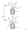
- Fig. 4 a schematic representation of a drive device with crank pin 24 in different rotational positions with a stroke h 1 , wherein in the region of a tap (40) a ball joint decoupling 41 (ball joint bearing unit) is provided
- the representations A and B show different rotational positions for the ball pin 24.
- a change of Distance d of the coupling between crank pin 24 and coupling member 25 changes the stroke h, which in Fig. 5 for a reduced stroke h 2 - at an increased distance d 2 > d 1 - is shown (h 2 ⁇ h 1 ).
- Fig. 5 show the two representations C and D again different rotational positions for the ball pin 24 (end points of the lifting movement).
- Fig. 6 and 7 show comparable to the Fig. 4 and 5 different rotational positions for the ball pin 24, which couples to the running as a flat connecting rod coupling member 25.
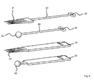
- Fig. 8 shows various representations of coupling components for coupling to the crank pin 24.
- the recess 26 is formed in a wire bracket 80, whereas in the lower embodiments in Fig. 8 a slot is provided as a recess 26.
- Two of the designs in Fig. 8 see a lancing device 81, whereas in the other two embodiments, a coupling element 82 is formed.
Landscapes
- Health & Medical Sciences (AREA)
- Engineering & Computer Science (AREA)
- Hematology (AREA)
- Life Sciences & Earth Sciences (AREA)
- Medical Informatics (AREA)
- Anesthesiology (AREA)
- Biomedical Technology (AREA)
- Heart & Thoracic Surgery (AREA)
- Virology (AREA)
- Dermatology (AREA)
- Animal Behavior & Ethology (AREA)
- General Health & Medical Sciences (AREA)
- Public Health (AREA)
- Veterinary Medicine (AREA)
- Surgical Instruments (AREA)
- Percussion Or Vibration Massage (AREA)
Priority Applications (1)
| Application Number | Priority Date | Filing Date | Title |
|---|---|---|---|
| EP15171698.2A EP2954927A1 (fr) | 2014-06-12 | 2015-06-11 | Module d'entraînement pour un appareil portatif pour la piqûre répétée d'une peau humaine et animale et propulsion |
Applications Claiming Priority (2)
| Application Number | Priority Date | Filing Date | Title |
|---|---|---|---|
| EP14172106 | 2014-06-12 | ||
| EP15171698.2A EP2954927A1 (fr) | 2014-06-12 | 2015-06-11 | Module d'entraînement pour un appareil portatif pour la piqûre répétée d'une peau humaine et animale et propulsion |
Publications (1)
| Publication Number | Publication Date |
|---|---|
| EP2954927A1 true EP2954927A1 (fr) | 2015-12-16 |
Family
ID=50942114
Family Applications (1)
| Application Number | Title | Priority Date | Filing Date |
|---|---|---|---|
| EP15171698.2A Withdrawn EP2954927A1 (fr) | 2014-06-12 | 2015-06-11 | Module d'entraînement pour un appareil portatif pour la piqûre répétée d'une peau humaine et animale et propulsion |
Country Status (2)
| Country | Link |
|---|---|
| US (1) | US20150367118A1 (fr) |
| EP (1) | EP2954927A1 (fr) |
Cited By (4)
| Publication number | Priority date | Publication date | Assignee | Title |
|---|---|---|---|---|
| EP3228349A1 (fr) | 2016-04-05 | 2017-10-11 | Werner Arnold | Dispositif de réglage de course pour dispositif de micro-aiguille en forme de l |
| USD960085S1 (en) | 2020-03-03 | 2022-08-09 | Fk Irons Inc. | Tattoo machine battery power supply |
| US11957861B2 (en) | 2020-01-28 | 2024-04-16 | Fk Irons Inc. | Pen style wireless tattoo machine, system, and kits |
| US12415059B2 (en) | 2020-03-03 | 2025-09-16 | Fk Irons Inc. | Device for offset wireless tattoo battery pack and methods of use |
Families Citing this family (9)
| Publication number | Priority date | Publication date | Assignee | Title |
|---|---|---|---|---|
| ES2753302T3 (es) * | 2014-06-12 | 2020-04-08 | Mt Derm Gmbh | Aparato manual para la punción repetida de una piel humana o animal |
| US10449346B2 (en) | 2015-06-05 | 2019-10-22 | Painful Pleasures, Inc. | Tattooing needle assembly |
| USD842468S1 (en) * | 2015-10-26 | 2019-03-05 | Painful Pleasures, Inc. | Tattoo needle assembly |
| US11260209B2 (en) | 2016-08-24 | 2022-03-01 | Fk Irons Inc. | Pen style microneedling machine apparatus |
| US11400268B2 (en) | 2018-10-11 | 2022-08-02 | Fk Irons Inc. | Electromagnetically driven tattoo machine and system |
| USD912818S1 (en) * | 2019-03-18 | 2021-03-09 | Hawink Inc | Tattoo machine pen |
| USD901685S1 (en) * | 2019-03-18 | 2020-11-10 | Hawink Inc | Tattoo machine pen |
| USD951439S1 (en) * | 2021-01-29 | 2022-05-10 | SIRE Industries, LLC | Multi-lumen spike |
| EP4085963B1 (fr) * | 2021-05-05 | 2025-03-12 | MT.DERM GmbH | Dispositif d'entraînement pour un appareil portatif de perçage local de la peau et appareil portatif |
Citations (6)
| Publication number | Priority date | Publication date | Assignee | Title |
|---|---|---|---|---|
| US5279552A (en) | 1993-01-11 | 1994-01-18 | Anton Magnet | Intradermal injection device |
| DE29919199U1 (de) | 1999-10-22 | 2000-01-20 | MediUm-TECH GmbH, 12681 Berlin | Tattoo- und/oder Permanent-Make-up-Farben-Handgerät |
| EP1495782A1 (fr) | 2003-07-08 | 2005-01-12 | MediUm-TECH Medizingeräte GmbH | Système de tatouage et de maquillage permanent |
| CN201759989U (zh) | 2010-04-27 | 2011-03-16 | 刘昌鑫 | 纹眉机的传动机构 |
| US20120279330A1 (en) | 2011-05-06 | 2012-11-08 | Mei-Chi-Na Hsinyen Co., Ltd. | Transmission mechanism of eyebrow tattoo machine |
| KR20130058843A (ko) | 2011-11-28 | 2013-06-05 | 이상현 | 문신장치 |
Family Cites Families (7)
| Publication number | Priority date | Publication date | Assignee | Title |
|---|---|---|---|---|
| US2567856A (en) * | 1948-09-08 | 1951-09-11 | Helen R Polk | Attachment for the spindle housings of drill presses |
| US4508106A (en) * | 1983-02-14 | 1985-04-02 | Angres Clinic, Ltd. | Microsurgical method for applying permanent eyelid liner |
| US5471102A (en) * | 1994-05-09 | 1995-11-28 | Becker; Gregory R. | Reciprocating shaft device |
| US7695486B2 (en) * | 2002-10-02 | 2010-04-13 | Linda Dixon | Intradermal color introducing needle device, and apparatus and method involving the same |
| TW580872U (en) * | 2003-01-20 | 2004-03-21 | Jen-Kuen Chen | Improved structure of transmission mechanism for eyebrow tattooing machine |
| PL1958659T3 (pl) * | 2007-02-14 | 2010-01-29 | Mt Derm Gmbh | Moduł napędowy przyrządu do miejscowego nakłuwania ludzkiej lub zwierzęcej skóry i przyrząd ręczny |
| PL2682146T3 (pl) * | 2012-07-05 | 2017-04-28 | Mt Derm Gmbh | Przyrząd ręczny do tatuowania lub nanoszenia makijażu permanentnego oraz moduł igłowy z regulowaną głębokością wkłuwania |
-
2015
- 2015-06-11 EP EP15171698.2A patent/EP2954927A1/fr not_active Withdrawn
- 2015-06-11 US US14/736,531 patent/US20150367118A1/en not_active Abandoned
Patent Citations (6)
| Publication number | Priority date | Publication date | Assignee | Title |
|---|---|---|---|---|
| US5279552A (en) | 1993-01-11 | 1994-01-18 | Anton Magnet | Intradermal injection device |
| DE29919199U1 (de) | 1999-10-22 | 2000-01-20 | MediUm-TECH GmbH, 12681 Berlin | Tattoo- und/oder Permanent-Make-up-Farben-Handgerät |
| EP1495782A1 (fr) | 2003-07-08 | 2005-01-12 | MediUm-TECH Medizingeräte GmbH | Système de tatouage et de maquillage permanent |
| CN201759989U (zh) | 2010-04-27 | 2011-03-16 | 刘昌鑫 | 纹眉机的传动机构 |
| US20120279330A1 (en) | 2011-05-06 | 2012-11-08 | Mei-Chi-Na Hsinyen Co., Ltd. | Transmission mechanism of eyebrow tattoo machine |
| KR20130058843A (ko) | 2011-11-28 | 2013-06-05 | 이상현 | 문신장치 |
Cited By (4)
| Publication number | Priority date | Publication date | Assignee | Title |
|---|---|---|---|---|
| EP3228349A1 (fr) | 2016-04-05 | 2017-10-11 | Werner Arnold | Dispositif de réglage de course pour dispositif de micro-aiguille en forme de l |
| US11957861B2 (en) | 2020-01-28 | 2024-04-16 | Fk Irons Inc. | Pen style wireless tattoo machine, system, and kits |
| USD960085S1 (en) | 2020-03-03 | 2022-08-09 | Fk Irons Inc. | Tattoo machine battery power supply |
| US12415059B2 (en) | 2020-03-03 | 2025-09-16 | Fk Irons Inc. | Device for offset wireless tattoo battery pack and methods of use |
Also Published As
| Publication number | Publication date |
|---|---|
| US20150367118A1 (en) | 2015-12-24 |
Similar Documents
| Publication | Publication Date | Title |
|---|---|---|
| EP2954927A1 (fr) | Module d'entraînement pour un appareil portatif pour la piqûre répétée d'une peau humaine et animale et propulsion | |
| EP2954926B1 (fr) | Appareil portatif pour la piqûre répétée d'une peau humaine ou animale | |
| EP1958659B1 (fr) | Module d'entraînement pour un dispositif de perçage local d'une peau humaine ou animale et appareil manuel | |
| EP1495782B1 (fr) | Système de tatouage et de maquillage permanent | |
| EP0305357B1 (fr) | Pièce à main dentaire | |
| EP4241824B1 (fr) | Dispositif à main permettant d'effectuer localement une ponction d'une peau | |
| EP2682146B1 (fr) | Appareil manuel pour appliquer tatouage ou maquillage permanent et module d'aiguille avec moyen d'ajuster profondeur de pénétration | |
| DE2852040C2 (de) | Vorrichtung zum wahlweisen Betätigen mindestens zweier Werkzeuge insbesondere für Zwecke der Zahnheilkunde | |
| EP2462979B1 (fr) | Dispositif de perçage répété de la peau et module de perçage | |
| DE2944391A1 (de) | Elektrisch angetriebenes handgeraet zur koerperpflege, insbesondere zahnbuerste oder massagegeraet | |
| EP2438867B1 (fr) | Instrument médical | |
| EP3363492B1 (fr) | Module d'aiguilles pour un dispositif commandé par entraînement destiné au perçage répété d'une peau humaine ou animale et appareil manuel | |
| EP2965779A1 (fr) | Module d'application pour un appareil portatif destiné à l'application répétée d'un élément d'application sur une peau humaine ou animale et appareil portatif | |
| EP2954925A1 (fr) | Appareil portatif pour la piqûre répétée d'une peau humaine et animale et propulsion | |
| EP4230250A1 (fr) | Dispositif manuel de micronedding pour percer localement la peau et articles | |
| EP3725358B1 (fr) | Système d'entraînement et module d'entraînement pour un appareil portatif destiné au percement local d'une peau humaine ou animale ainsi qu'appareil portatif | |
| DE19836376A1 (de) | Vorrichtung zum Aufbringen von Permanent-Make-up | |
| DE3200711C2 (fr) | ||
| EP3254584A1 (fr) | Appareil manuel destine au soin de la peau | |
| EP4085963B1 (fr) | Dispositif d'entraînement pour un appareil portatif de perçage local de la peau et appareil portatif | |
| EP2671610B1 (fr) | Module d'aiguille avec adaptation automatique de la fréquence et de l'amplitude | |
| EP4245283B1 (fr) | Appareil portatif de micro-aiguillage permettant de stimuler localement la peau, dispositif de stimulation de la peau et article | |
| EP4260897A1 (fr) | Dispositif d'entrainement pour un appareil portatif permettant d'inciser localement une peau et appareil portatif | |
| DE10306459B4 (de) | Tätowiermaschine | |
| EP4260896B1 (fr) | Appareil portatif permettant de perforer localement une peau humaine ou animale |
Legal Events
| Date | Code | Title | Description |
|---|---|---|---|
| PUAI | Public reference made under article 153(3) epc to a published international application that has entered the european phase |
Free format text: ORIGINAL CODE: 0009012 |
|
| AK | Designated contracting states |
Kind code of ref document: A1 Designated state(s): AL AT BE BG CH CY CZ DE DK EE ES FI FR GB GR HR HU IE IS IT LI LT LU LV MC MK MT NL NO PL PT RO RS SE SI SK SM TR |
|
| AX | Request for extension of the european patent |
Extension state: BA ME |
|
| 17P | Request for examination filed |
Effective date: 20160609 |
|
| RBV | Designated contracting states (corrected) |
Designated state(s): AL AT BE BG CH CY CZ DE DK EE ES FI FR GB GR HR HU IE IS IT LI LT LU LV MC MK MT NL NO PL PT RO RS SE SI SK SM TR |
|
| STAA | Information on the status of an ep patent application or granted ep patent |
Free format text: STATUS: THE APPLICATION HAS BEEN WITHDRAWN |
|
| 18W | Application withdrawn |
Effective date: 20180516 |