EP2954945B1 - Procédé et dispositif pour mélanger des fluides - Google Patents
Procédé et dispositif pour mélanger des fluides Download PDFInfo
- Publication number
- EP2954945B1 EP2954945B1 EP14171930.2A EP14171930A EP2954945B1 EP 2954945 B1 EP2954945 B1 EP 2954945B1 EP 14171930 A EP14171930 A EP 14171930A EP 2954945 B1 EP2954945 B1 EP 2954945B1
- Authority
- EP
- European Patent Office
- Prior art keywords
- fluid
- mixing chamber
- inlet
- wall
- oil
- Prior art date
- Legal status (The legal status is an assumption and is not a legal conclusion. Google has not performed a legal analysis and makes no representation as to the accuracy of the status listed.)
- Active
Links
Images


Classifications
-
- B—PERFORMING OPERATIONS; TRANSPORTING
- B01—PHYSICAL OR CHEMICAL PROCESSES OR APPARATUS IN GENERAL
- B01F—MIXING, e.g. DISSOLVING, EMULSIFYING OR DISPERSING
- B01F35/00—Accessories for mixers; Auxiliary operations or auxiliary devices; Parts or details of general application
- B01F35/71—Feed mechanisms
- B01F35/717—Feed mechanisms characterised by the means for feeding the components to the mixer
- B01F35/71725—Feed mechanisms characterised by the means for feeding the components to the mixer using centrifugal forces
-
- B—PERFORMING OPERATIONS; TRANSPORTING
- B01—PHYSICAL OR CHEMICAL PROCESSES OR APPARATUS IN GENERAL
- B01F—MIXING, e.g. DISSOLVING, EMULSIFYING OR DISPERSING
- B01F25/00—Flow mixers; Mixers for falling materials, e.g. solid particles
- B01F25/10—Mixing by creating a vortex flow, e.g. by tangential introduction of flow components
-
- B—PERFORMING OPERATIONS; TRANSPORTING
- B01—PHYSICAL OR CHEMICAL PROCESSES OR APPARATUS IN GENERAL
- B01J—CHEMICAL OR PHYSICAL PROCESSES, e.g. CATALYSIS OR COLLOID CHEMISTRY; THEIR RELEVANT APPARATUS
- B01J14/00—Chemical processes in general for reacting liquids with liquids; Apparatus specially adapted therefor
-
- B—PERFORMING OPERATIONS; TRANSPORTING
- B01—PHYSICAL OR CHEMICAL PROCESSES OR APPARATUS IN GENERAL
- B01F—MIXING, e.g. DISSOLVING, EMULSIFYING OR DISPERSING
- B01F23/00—Mixing according to the phases to be mixed, e.g. dispersing or emulsifying
- B01F23/40—Mixing liquids with liquids; Emulsifying
- B01F23/405—Methods of mixing liquids with liquids
-
- B—PERFORMING OPERATIONS; TRANSPORTING
- B01—PHYSICAL OR CHEMICAL PROCESSES OR APPARATUS IN GENERAL
- B01F—MIXING, e.g. DISSOLVING, EMULSIFYING OR DISPERSING
- B01F23/00—Mixing according to the phases to be mixed, e.g. dispersing or emulsifying
- B01F23/40—Mixing liquids with liquids; Emulsifying
- B01F23/45—Mixing liquids with liquids; Emulsifying using flow mixing
-
- B—PERFORMING OPERATIONS; TRANSPORTING
- B01—PHYSICAL OR CHEMICAL PROCESSES OR APPARATUS IN GENERAL
- B01F—MIXING, e.g. DISSOLVING, EMULSIFYING OR DISPERSING
- B01F25/00—Flow mixers; Mixers for falling materials, e.g. solid particles
- B01F25/30—Injector mixers
- B01F25/31—Injector mixers in conduits or tubes through which the main component flows
- B01F25/313—Injector mixers in conduits or tubes through which the main component flows wherein additional components are introduced in the centre of the conduit
- B01F25/3131—Injector mixers in conduits or tubes through which the main component flows wherein additional components are introduced in the centre of the conduit with additional mixing means other than injector mixers, e.g. screens, baffles or rotating elements
-
- B—PERFORMING OPERATIONS; TRANSPORTING
- B01—PHYSICAL OR CHEMICAL PROCESSES OR APPARATUS IN GENERAL
- B01J—CHEMICAL OR PHYSICAL PROCESSES, e.g. CATALYSIS OR COLLOID CHEMISTRY; THEIR RELEVANT APPARATUS
- B01J19/00—Chemical, physical or physico-chemical processes in general; Their relevant apparatus
- B01J19/24—Stationary reactors without moving elements inside
- B01J19/2405—Stationary reactors without moving elements inside provoking a turbulent flow of the reactants, such as in cyclones, or having a high Reynolds-number
-
- B—PERFORMING OPERATIONS; TRANSPORTING
- B01—PHYSICAL OR CHEMICAL PROCESSES OR APPARATUS IN GENERAL
- B01J—CHEMICAL OR PHYSICAL PROCESSES, e.g. CATALYSIS OR COLLOID CHEMISTRY; THEIR RELEVANT APPARATUS
- B01J4/00—Feed or outlet devices; Feed or outlet control devices
-
- B—PERFORMING OPERATIONS; TRANSPORTING
- B01—PHYSICAL OR CHEMICAL PROCESSES OR APPARATUS IN GENERAL
- B01F—MIXING, e.g. DISSOLVING, EMULSIFYING OR DISPERSING
- B01F25/00—Flow mixers; Mixers for falling materials, e.g. solid particles
- B01F2025/91—Direction of flow or arrangement of feed and discharge openings
- B01F2025/914—Tangential flow, i.e. flow spiraling in a tangential direction in a flat plane or belt-like area
-
- B—PERFORMING OPERATIONS; TRANSPORTING
- B01—PHYSICAL OR CHEMICAL PROCESSES OR APPARATUS IN GENERAL
- B01F—MIXING, e.g. DISSOLVING, EMULSIFYING OR DISPERSING
- B01F2101/00—Mixing characterised by the nature of the mixed materials or by the application field
- B01F2101/505—Mixing fuel and water or other fluids to obtain liquid fuel emulsions
-
- B—PERFORMING OPERATIONS; TRANSPORTING
- B01—PHYSICAL OR CHEMICAL PROCESSES OR APPARATUS IN GENERAL
- B01J—CHEMICAL OR PHYSICAL PROCESSES, e.g. CATALYSIS OR COLLOID CHEMISTRY; THEIR RELEVANT APPARATUS
- B01J2204/00—Aspects relating to feed or outlet devices; Regulating devices for feed or outlet devices
- B01J2204/007—Aspects relating to the heat-exchange of the feed or outlet devices
-
- B—PERFORMING OPERATIONS; TRANSPORTING
- B01—PHYSICAL OR CHEMICAL PROCESSES OR APPARATUS IN GENERAL
- B01J—CHEMICAL OR PHYSICAL PROCESSES, e.g. CATALYSIS OR COLLOID CHEMISTRY; THEIR RELEVANT APPARATUS
- B01J2219/00—Chemical, physical or physico-chemical processes in general; Their relevant apparatus
- B01J2219/00049—Controlling or regulating processes
- B01J2219/00164—Controlling or regulating processes controlling the flow
-
- Y—GENERAL TAGGING OF NEW TECHNOLOGICAL DEVELOPMENTS; GENERAL TAGGING OF CROSS-SECTIONAL TECHNOLOGIES SPANNING OVER SEVERAL SECTIONS OF THE IPC; TECHNICAL SUBJECTS COVERED BY FORMER USPC CROSS-REFERENCE ART COLLECTIONS [XRACs] AND DIGESTS
- Y02—TECHNOLOGIES OR APPLICATIONS FOR MITIGATION OR ADAPTATION AGAINST CLIMATE CHANGE
- Y02P—CLIMATE CHANGE MITIGATION TECHNOLOGIES IN THE PRODUCTION OR PROCESSING OF GOODS
- Y02P30/00—Technologies relating to oil refining and petrochemical industry
- Y02P30/20—Technologies relating to oil refining and petrochemical industry using bio-feedstock
Definitions
- the present description relates to mixing fluids.
- it relates to mixing fluids effectively by injecting fresh fluid feed into a spiral stream of recycled fluid feed.
- the method is useful e.g. in chemical processes where corrosive fresh fluid feeds are mixed into a recycled fluid feed. Particular use is found in processing hydrocarbons, such as diesel range hydrocarbons from renewable source of biological origin, e.g. from bio oils and fats.
- the invention is also useful in controlling temperature profile of the reactor.
- Plant oils and fats, as well as animal oils and fats typically contain 0-30 wt-% of free fatty acids, FFA.
- FFAs are formed during enzymatic hydrolysis of triglycerides especially when oil seeds are kept in humid atmosphere.
- Free fatty acids can also be formed during purification of bio oils and fats, especially during caustic wash, i.e. alkali catalyzed hydrolysis.
- the fatty acid composition, size and saturation degree may vary considerably in feed stocks from different origins.
- the melting point of bio oil or fat is mainly a consequence of the saturation degree. Fats are more saturated than liquid oils and require less hydrogen for hydrogenation of double bonds.
- Free fatty acids are very corrosive because of their acidity. They attack against materials they are in contact with which may cause corrosion on equipment used in processes involving FFAs, such as piping and reactors.
- FFAs also promote undesirable side reactions. Unsaturated feeds and free fatty acids in bio oils and fats promote the formation of heavy molecular weight compounds, which may cause plugging of the preheating section and decrease catalyst activity and life. Double bonds in unsaturated FFAs also promote various other side reactions, such as oligomerisation/polymerization, cyclisation/aromatisation and cracking reactions. These reactions cause many problems in the process and deactivate catalysts, increase hydrogen consumption and reduce diesel yield.
- Fatty acids may also promote the formation of heavy compounds.
- the boiling range of these heavy compounds is different from the range of diesel fuel and may shorten the life of isomerisation catalyst. Due to the free fatty acids contained in bio oils and fats, the formation of heavy molecular weight compounds are significantly increased compared to triglyceridic bio feeds which have only low amount of free fatty acids ( ⁇ 1%).
- EP1741768A1 describes a process for the manufacture of diesel range hydrocarbons wherein a feed is hydrotreated in a hydrotreating step and isomerised in an isomerization step and a feed comprising fresh feed containing more than 5 w-% of free fatty acids and at least one diluting agent is hydrotreated at a reaction temperature of 200-400 °C, in a hydrotreating reactor in the presence of catalyst, and the volume ratio of the diluting agent to fresh feed is 5-30:1.
- Hydrodeoxygenation, HDO, step is disclosed as a hydrogenolysis process for removing oxygen from oxygen containing compounds and FFA-feeds.
- Free fatty acids are corrosive and they can attack against materials of unit or catalyst and promote some side reactions. Free fatty acids react very efficiently with metal impurities producing metal carboxylates, which promote undesirable side reaction chemistry.
- the corrosiveness of FFAs present in renewable sources of hydrocarbons has limited use of renewable sources in manufacturing diesel fuel.
- the high concentration of FFAs in fresh feeds prevents feeding high concentrations of fresh feed into recycle feed without exposing e.g. feed system, heat exchanger and reactor to corrosion.
- the risk of corrosion is particularly high above the reaction bed where fresh feed is mixed with the recycle, such as at HDO.
- Corrosion rate is affected by factors such as materials used in the process, operating temperature, organic acid concentration and sulphide formation.
- Undesired oxygen may be removed from fatty acids or their esters by deoxygenation reactions.
- the deoxygenation of bio oils and fats, which are oils and fats based on biological material, to produce hydrocarbons suitable as diesel fuel products, may be carried out by catalytic hydrotreating.
- EP1741768A1 also describes an improved process for the manufacture of diesel range hydrocarbons from bio oils and fats, wherein the hydrotreatment of triglyceride feedstock containing free fatty acids is carried out using dilution of fresh feed and reduced reaction temperature.
- the dilution agent is selected from hydrocarbons and recycled product of the process i.e. product recycle or mixtures thereof.
- a ratio of at least 5:1 (recycle:fresh) significantly decreased the formation of high molecular weight products, when the feedstock containing 10 wt-% of free fatty acids (calculated from fresh oil) was used.
- at least 5:1 or 4:1 recycle ratio and reduced reaction temperature free fatty acids can be processed without the need for deacidification and high quality hydrocarbons suitable for the diesel fuel pool were obtained.
- Corrosion prevention has previously been achieved by cladding the exposed surfaces, adding a corrosion inhibitor, anti-corrosion agents, or changing the materials (corrosion resistant material) used in the exposed surfaces. These methods are known for example from US2012053377 .
- US20120216450 describes a method of converting feeds from renewable sources in co-processing with a petroleum feed using a catalyst based on nickel and molybdenum.
- US8440875 describes a method of making a diesel fuel from a renewable feedstock.
- Ammonia or an amine compound is used to neutralize the organic acids in the renewable feedstock.
- the ammonia or amine compound must be removed from the product mixture before the isomerization zone so that it does not affect the isomerization catalyst.
- the use of ammonia or amine compounds could allow for the metallurgy reductions in the process equipment.
- US20120255223 discloses a process for conversion of FFA containing oils to biodiesel by converting high FFA containing feed stocks (FFA 20-85%) without pretreatment or purification to biodiesel in the presence of macro reticular and gel type acidic heterogeneous resin followed by transesterification in presence of homogeneous basic catalyst and separation of biodiesel and glycerin.
- FR2989006A1 discloses a catalytic reactor with a quench device provided with tangential injection of a quench fluid.
- US6183702B1 discloses a distributor assembly for a multi-bed, downflow catalytic reactor, comprising the features of the preamble of claim 15.
- US2013/064740A1 discloses a vortex-type mixing device for a down-flow hydroprocessing reactor.
- the present inventors have surprisingly found an effective method of mixing fluids in accordance with claim 1 and a fluid mixer in accordance with claim 15.
- the first aspect of the invention provides a method of mixing fluids in a fluid mixer, the fluid mixer comprising a first inlet, a second inlet, an outlet, and a substantially cylindrical mixing chamber, the mixing chamber comprising a wall, a top plate, and a bottom plate, and the method comprising
- a fluid mixer for mixing fluids comprising
- An advantage of the method and the fluid mixer is the capability to effectively mix into the first fluid a second fluid.
- the second fluid may have a high concentration of at least one corrosive agent.
- Prior processes involving mixing corrosive fluids have required protecting reactors by expensive protecting layers.
- corrosive fluids have been injected in low concentrations to avoid contact of high concentration of corrosive agents with the mixer or reactor surfaces, in particular the mixing chamber walls.
- the effective mixing of the present method removes the need for extensive protecting layers in the reactor shell and in the main distributor (below the quench box). Additionally, extensive use of diluting fluids can be avoided. With prior technology only fresh feed with FFA contents of less than about 10% has been possible without additional protection from corrosion.
- the present method enables mixing second fluid having high concentration FFAs.
- High FFA content of some hydrocarbon sources of biological origin has previously limited extensive use of highly feasible feedstocks in refinery.
- the increased use of feedstocks with higher FFA content has a positive impact on feasibility of refinery units.
- the method is especially advantageous in HDO reactor optionally involving multiple beds.
- the method allows using high FFA raw material streams that are inexpensive and attractive sources for bio fuel production, but which have previously been difficult or impossible to use because of their corrosive nature.
- the present mixing method allows up to 100% FFA content in the second fluid.
- an advantage of the method is efficient mixing of the fluid streams into a more homogeneous stream which helps to maintain optimal temperature profile in the reactor and helps to avoid unwanted side reactions.
- the mixing method and the fluid mixer according to the invention allows an assembly which is very compact, making the fluid mixer suitable to be installed, and the mixing method to be used, in existing reactors with few modifications in the reactor.
- the compact structure is particularly advantageous in multibed reactors having several points of injection for the fresh fluid comprising a corrosive agent.
- the present mixing method and fluid mixer are particularly advantageous when used in hydrotreating where product recycle or another dilution agent in the hydrotreatment step is used as the first fluid and the second fluid comprises fresh feed with high FFA content.
- the fluid mixer allows effective mixing without using mixing blades or similar for mixing the fluids.
- the fluid mixer can be implemented as a compact unit that can be easily fitted into reactors.
- the present invention provides a novel mixing method and a fluid mixer.
- the modified mixing chamber reduces the corrosion problem and allows using increased FFA content in the fresh feed and in the mixed feed exiting the mixing chamber.
- the corrosion product is very soluble in hot hydrocarbon stream, there is usually no protective film or corrosion scale on steel surfaces of the system.
- the soluble corrosion product can react with H 2 S present in the process to form poorly soluble FeS deposits that cause plugging problems.
- FeS deposits may occur according to the reaction Fe(RCOO) 2 + H 2 S --> FeS + 2RCOOH (2)
- Feed nozzle of the second fluid, as well as internal piping including quench box for the second catalyst bed can become in contact with fresh feed at high temperatures.
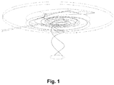
- the mixing chamber has substantially cylindrical shape. Cylindrical shape is preferred as it enhances spiral flow inside the mixing chamber. However, the first inlet forms asymmetry to the cylindrical shape as the inlet enters the mixing chamber near the wall of the mixing chamber, as is seen in Fig. 1 . Consequently, the shape of the mixing chamber is not perfectly cylindrical.
- the first inlet provides a spiral stream of the first fluid inside the mixing chamber.
- the first inlet is in the form of a pipe or a ramp, which descends from outside the mixing chamber through the top plate and to the bottom of the mixing chamber, thereby forming a curved passage for the first fluid to enter the mixing chamber near the wall of the mixing chamber.
- the spiral movement of the first fluid flow initially continues near the wall of the mixing chamber until the flow reaches the entry point of the first fluid, i.e. the end of the first inlet. After this point the stream begins the second round of rotation and continues the second and subsequent cycles closer to the center of the mixing chamber, thus forming a spiral stream.
- the stream continues spiral movement inside the mixing chamber as the first fluid enters through the first inlet, as well as the geometry of the mixing chamber, cause the stream to rotate and flow towards the center of the mixing chamber wherein the outlet in the bottom plate is situated at the center of the mixing chamber.
- the second fluid is injected tangential to the wall of the mixing chamber.
- the tangential injection may be accomplished by injecting the second fluid through a fluid inlet nozzle directed downstream.
- the second inlet may enter the mixing chamber through the wall of the mixing chamber, e.g. as a pipe with a nozzle which opens into the stream of the first fluid.
- the concentration of the second fluid decreases towards the wall of the mixing chamber as it mixes with the first fluid flowing around the second inlet, as well as flowing between the second inlet and the wall of the mixing chamber.
- the concentration of the second fluid at the wall of the mixing chamber may be as low as below 1 wt-%.
- the mixed fluids exit the mixing chamber through an outlet in the bottom plate as a vortex.
- the outlet is provided in the bottom plate and it is concentric with both the spiral flow axis to achieve enhanced mixing.
- the outlet opens into a reactor comprising a wall.
- the rotational stream of fluids forms a vortex which extends inside the reactor below the fluid mixer essentially concentrically with the reactor.
- efficient mixing of the fluids is obtained and, consequently, very high concentrations of corrosive agents, such as FFA, in the second fluid can be injected without exposing the fluid mixer wall directly to the corrosive second fluid.
- the opening of the outlet may be circular and concentric to the mixing chamber.
- the first inlet has a height corresponding to the height of the mixing chamber at the end of the inlet entering the mixing chamber.
- the inlet is a ramp and the cross section of the ramp opening is rectangular having the base and the top edges that are longer than the side edges.
- the circumferential length of the first inlet, such as a ramp is less than a full circle, preferably one fourth of a circle.
- the inlet is tubular, i.e. a pipe.
- the first inlet is a tangentially directed downcomer.
- the second inlet may comprise a nozzle with an inner sleeve in particular if the temperature is high, such as exceeds approx. 225°C. This provides additional protection for the second inlet to prevent corrosion caused by the corrosive agent while it is injected into the recycle feed and before it is effectively mixed with the recycle feed by the present fluid mixer, making it less corrosive.
- the second fluid comprises an agent which is corrosive.
- the corrosive nature of the second fluid may affect the walls of the mixing chamber, the reactor walls, or both.
- the corrosive nature of the second fluid prevents injecting it in high concentration directly inside the mixing chamber or to the reactor in high concentrations without using the present method to effectively mix the fluids. Consequently, in prior methods the ratio of the recycle feed to the fresh feed must have been kept high because ineffective mixing of the feeds has made it necessary to keep the amount of the corrosive fresh feed low as a precaution in order to control exposure of the system to corrosive agents in the fresh feed.
- the volume ratio of the first fluid to the second fluid in the fluid stream exiting the mixing chamber is from 1:1 to 15:1, preferably from 3:1 to 6:1, such as 1:1, 2:1, 3:1, 4:1, 5:1, 6:1, 7:1, 8:1, 9:1, 10:1, 11:1, 12:1, 13:1, 14:1 or 15:1.
- the first fluid may preferably be fed from 50 to 300 t/h, such as 50, 60, 70, 80, 90, 100, 110, 120, 130, 140, 150, 160, 170, 180, 190, 200, 210, 220, 230, 240, 250, 260, 270, 280, 290 or 300 t/h.
- the second fluid may preferably be fed from 0.5 to 60 t/h, such as 0.5, 0.6, 0.7, 0.8, 0.9, 1, 2, 3, 4, 5, 6, 7, 8, 9, 10, 11, 12, 13, 14, 15, 16, 17, 18, 19, 20, 25, 30, 35, 40, 45, 50, 55 or 60 t/h.
- the flow rates of the first and the second fluid may be selected such that the above mentioned volume ratios for the first and the second fluids are obtained.
- the feed of the second fluid may be divided accordingly depending on the number of beds: for two beds, and a total flow rate of 60 t/h for the second fluid, 30 t/h feeds for each bed may be used; for three beds the second fluid feed may be divided into three 20 t/h feeds for each bed, accordingly.
- the flow rate of the second feed may vary in the individual beds of a multibed reactor as long as the total flow rate of the second feed is kept within the above range.
- the second fluid comprises free fatty acids as a corrosive agent up to 100 % w/w, preferably up to 5, 10, 15, 20, 25, 30, 35, 40, 45, 50, 55, 60, 65, 70, 75, 80, 85, 90, or 95 % w/w.
- the second fluid comprises one or more free fatty acid distillates such as palm fatty acid distillate and/or soya free fatty acid distillate; one or more free fatty acid containing bio based feedstock such as crude and refined palm based oil, technical corn oil, tall oil, seed oil, animal fat, waste cooking oil, jatropha curcas oil, fish oil, microbial oil, and/or algae oil; by-products from fatty acid methyl ester and bio based chemicals production and/or oil derived from ligno-cellulosic biomass; and/or one or more lower molecular weight acids containing bio based feedstock such as pyrolysis oil and/or sludge palm oil.
- bio based feedstock such as crude and refined palm based oil, technical corn oil, tall oil, seed oil, animal fat, waste cooking oil, jatropha curcas oil, fish oil, microbial oil, and/or algae oil
- the flow rate of the first fluid is higher than the flow rate of the second fluid at the points of entry of the fluids into the mixing chamber such that the fluids rotate inside the mixing chamber primarily because of the momentum of the first fluid.
- the flow inside the mixing chamber is controlled by injecting the second fluid into and concurrent to the first fluid such that the second fluid does not touch the wall of the mixing chamber.
- the flow rates of the first and the second fluid are selected such that the spiral flow rotates at 0.5-2.0 r/s inside the mixing chamber.
- the second fluid is injected into the first fluid through an opening in a nozzle which is surrounded by the first fluid.
- the first fluid streams through the mixing chamber in a spiral stream and surrounds the space into which the second fluid is injected, thereby protecting the mixing chamber wall from the corrosive agents present in the second fluid.
- the nozzle for the second fluid may be positioned inside the mixing chamber such that the nozzle directs the second fluid inside the rotating stream which originates predominantly or exclusively from the first fluid.
- the height of the mixing chamber is smaller than its diameter, preferably the height to diameter ratio is from 0.006 to 0.3, most preferably from 0.03 to 0.15, such as 0.006, 0.007, 0.008, 0.009, 0.01, 0.015, 0.02, 0.025, 0.026, 0.027, 0.028, 0.029, 0.03, 0.031, 0.032, 0.033, 0.034, 0.035, 0.04, 0.045, 0.05, 0.055, 0.06, 0.065, 0.07, 0.075, 0.08, 0.085, 0.09, 0.095, 0.1, 0.11, 0.12, 0.13, 0.14, 0,141, 0.142, 0.143, 0.144, 0.145, 0.146, 0.147, 0.148, 0.149, 0.15, 0.151, 0.152, 0.153, 0.154, 0.155, 0.156, 0.157, 0.158, 0.159, 0.16, 0.17, 0.18, 0.19, 0.2, 0,21, 0.22, 0.23, 0.24, 0.25, 0.15, such
- the method is for mixing fluids in a downflow reactor or in a reactor comprising multiple beds.
- the method is for mixing FFA containing renewable hydrocarbon source of biological origin as the second fluid and incoming process feed as the first stream to feed reactants into a HDO reactor.
- the second fluid comprises up to 100% FFA, preferably up to 5, 10, 15, 20, 25, 30, 35, 40, 45, 50, 55, 60, 65, 70, 75, 80, 85, 90, or 95 % w/w.
- the method produces very efficient mixing and allows feeding second fluids comprising high concentration of corrosive agent, such as FFA.
- the substantially cylindrical mixing chamber of the fluid mixer is defined by a wall, a top plate, and a bottom plate.
- the fluids are mixed inside this defined space by the effect of the rotating first fluid into which the second fluid is injected.
- the fluid mixer is configured to direct the spiral stream of the fluids to the exterior of the mixing chamber as a vortex through the outlet in the bottom plate, the outlet being concentric with the spiral vortex axis.
- the second fluid As the second fluid is injected inside the first fluid and tangentially to the wall of the mixing chamber, the second fluid does not significantly contact the wall of the mixing chamber.
- the second fluid may comprise a corrosive agent which may corrode the wall. It is thus advantageous to avoid contacting the second fluid with the wall of the mixing chamber in order to prevent corrosion in said wall.
- the flow of the second fluid may be controlled such that sufficient mixing is obtained, depending on the type of the second fluid, as well as e.g. the particular shape of the mixing chamber.
- the inlet for the second fluid may enter the mixing chamber through the wall of the mixing chamber.
- the opening in the bottom plate of the mixing chamber directs the spiral flow of the fluids outside the mixing chamber.
- a vortex of the fluids is formed in which the mixing of the fluids continues with the content of the fluids in the reactor space.
- the second inlet is directed downstream and separated from the wall of the mixing chamber. This further enhances mixing and avoids direct contact between the wall and the second fluid.
- the outlet is circular and has a diameter smaller than the diameter of the mixing chamber. This yields efficient discharge of the fluids and enhances spiral stream inside the mixing chamber.
- the second fluid comprises a corrosive agent.
- the corrosive agent is renewable feedstock having more than 10% FFA.
- the FFA content may be as high as 100%.
- the fluid mixer is for use in the mixing method.
- the method is for hydrotreating renewable feedstock having more than 10% free fatty acid.
- the above fluid mixer is used.
- Example 1 The fluid mixer
- the maximum FFA content of the feed was investigated assuming that the whole fluid mixer material can tolerate 100% FFA.
- the reactor wall material is not changed and no additional protective layers are used in the reactor. Therefore, the fluid mixer is designed such that the FFA content near the reactors walls does not exceed 12 w-%.
- An embodiment of a fluid mixer according to the invention is shown in Fig. 1 .
- the flow of fluids inside the fluid mixer was simulated.
- the first fluid enters the mixer at 140 t/h from the top and the second fluid is injected into the stream inside the mixer (see Fig. 1 ).
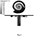
- Fig. 1 In order to increase the FFA concentration in the quench inlet, i.e. the second inlet, the design shown in Fig. 1 was simulated. FFA feed concentrations of 50, 80 and 100 w-% were used. Fig. 2-4 shows the FFA mass fraction in scale 0-12 w-%. Concerning the 12 w-% FFA limit, 100 w-% FFA in the second fluid is acceptable if the walls can tolerate max. 8 w-% or 12 w-% depending on the quench box material.
Landscapes
- Chemical & Material Sciences (AREA)
- Chemical Kinetics & Catalysis (AREA)
- Organic Chemistry (AREA)
- Production Of Liquid Hydrocarbon Mixture For Refining Petroleum (AREA)
Claims (17)
- Procédé permettant de mélanger des fluides dans un mélangeur de fluide, le mélangeur de fluide comprenant une première entrée, une deuxième entrée, une sortie, et une chambre de mélange sensiblement cylindrique, la chambre de mélange comprenant une paroi, une plaque supérieure et une plaque inférieure, et le procédé comprenant les étape consistant àa. faire passer un premier courant de fluide dans la chambre de mélange au travers de la première entrée, la première entrée présentant des ouvertures dans la plaque supérieure et à l'intérieur de la chambre de mélange, une paroi extérieure de la première entrée s'étendant vers la paroi de la chambre de mélange et descendant vers le bas la chambre de mélange ;b. fournir un courant en spirale du premier fluide à l'intérieur de la chambre de mélange au travers de la première entrée, la première entrée descendant vers la chambre de mélange sous la forme d'une rampe ou d'un tuyau, et formant une asymétrie dans la forme cylindrique pour améliorer le courant en spirale dans la chambre de mélange ;c. injecter au travers de la deuxième entrée, et tangentiellement à la paroi de la chambre de mélange, un deuxième fluide à l'intérieur du courant en spirale du premier fluide ; etd. diriger le courant en spirale des fluides vers l'extérieur de la chambre de mélange comme un vortex au travers de la sortie, la sortie étant prévue dans plaque inférieure, et la sortie étant concentrique avec l'axe de l'écoulement en spirale.
- Procédé selon la revendication 1, dans lequel la première entrée a une hauteur correspondant à la hauteur de la chambre de mélange.
- Procédé selon la revendication 1 ou 2, dans lequel la deuxième entrée comprend une buse avec un manchon intérieur pour protéger la deuxième entrée de la corrosion.
- Procédé selon l'une quelconque des revendications 1 à 3, dans lequel le deuxième fluide comprend un agent qui est corrosif.
- Procédé selon l'une quelconque des revendications 1 à 4, dans lequel le rapport en volume du premier fluide sur le deuxième fluide dans le courant de fluide sortant de la chambre de mélange est compris dans une plage allant de 1 : 1 à 15 : 1, de préférence de 3 : 1 à 6 : 1.
- Procédé selon l'une quelconque des revendications 1 à 5, dans lequel le deuxième fluide comprenda. un ou plusieurs distillats d'acides gras libres tels que le distillat d'acide gras de palme et / ou le distillat d'acide gras libres de soja,b. un ou plusieurs acides gras libres contenant de la matière première d'origine biologique telle que l'huile à base de palme brute et raffinée, l'huile de maïs technique, l'huile de tall, l'huile de graines, la graisse animales, l'huile de cuisson usagée, l'huile de jatropha curcas, l'huile de poisson, l'huile microbienne, et / ou l'huile d'algues,c. des sous-produits d'ester de méthyle d'acide gras et des produits chimiques et / ou des huiles d'origine biologique dérivés d'une biomasse lignocellulosique, et / oud. un ou plusieurs acides de poids moléculaire inférieur contenant de la matière première d'origine biologique telle que l'huile de pyrolyse et / ou de la boue d'huile de palme.
- Procédé selon l'une quelconque des revendications 1 à 6, dans lequel le débit d'écoulement du premier fluide est supérieur au débit d'écoulement du deuxième fluide.
- Procédé selon l'une quelconque des revendications 1 à 7, dans lequel l'écoulement à l'intérieur de la chambre de mélange est contrôlé par l'injection du deuxième fluide dans et simultanément au premier fluide de telle sorte que le deuxième fluide ne touche pas la paroi de la chambre de mélange.
- Procédé selon l'une quelconque des revendications 1 à 8, dans lequel l'écoulement en spirale tourne de 0,5 à 2 r / s à l'intérieur de la chambre de mélange.
- Procédé selon l'une quelconque des revendications 1 à 9, dans lequel le premier fluide est introduit de 50 à 300 t / h et le deuxième fluide est introduit de 0,5 à 20 t / h.
- Procédé selon l'une quelconque des revendications 1 à 10, dans lequel la hauteur de la chambre de mélange est inférieure à son diamètre, de préférence, le rapport de la hauteur sur le diamètre est de 0,006 à 0,3, de préférence de 0,03 à 0,15.
- Procédé selon l'une quelconque des revendications 1 à 11 permettant de mélanger des fluides dans un réacteur à flux descendant ou dans un réacteur comprenant plusieurs lits.
- Procédé selon l'une quelconque des revendications 1 à 12 permettant de mélanger des acides gras libres contenant des sources d'hydrocarbures renouvelables d'origine biologique en tant que deuxième fluide et du produit d'alimentation de traitement entrant en tant que premier fluide pour fournir des réactifs dans un réacteur HDO.
- Procédé selon l'une quelconque des revendications 1 à 13, dans lequel le deuxième fluide comprend jusqu'à 100% d'acides gras libres, de préférence jusqu'à 5, 10, 15, 20, 25, 30, 35, 40, 45, 50, 55, 60, 65, 70, 75, 80, 85, 90 ou 95% p / p.
- Mélangeur de fluide comprenanta. une chambre de mélange sensiblement cylindrique qui est définie par une paroi, une plaque supérieure et une plaque inférieure ;b. une première entrée pour faire passer un premier courant de fluide dans la chambre de mélange, le première entrée présentant des ouvertures dans la plaque supérieure et à l'intérieur de la chambre de mélange, une paroi extérieure de la première entrée s'étendant vers la paroi de la chambre de mélange et descendant vers le bas de la chambre de mélange, la première entrée étant configurée pour fournir un courant en spirale du premier fluide à l'intérieur de la chambre de mélange, la première entrée descendant vers la chambre de mélange sous la forme d'une rampe ou d'un tuyau, et formant une asymétrie dans la forme cylindrique pour améliorer le courant en spirale dans la chambre de mélange ;caractérisé en ce qu'il comprend en outrec. une deuxième entrée pour injecter tangentiellement à la paroi de la chambre de mélange un deuxième fluide dans le courant en spirale du premier fluide de telle sorte que la concentration du deuxième fluide diminue en direction de la paroi de la chambre de mélange, la deuxième entrée comprenant de manière optionnelle une buse avec un manchon intérieur pour protéger la deuxième entrée de la corrosion ; etd. une sortie dans la plaque inférieure, le mélangeur de fluide étant configuré de manière à diriger le courant en spirale des fluides vers l'extérieur de la chambre de mélange comme un vortex au travers de la sortie, la sortie étant concentrique avec la chambre de mélange.
- Mélangeur de fluide selon la revendication 15, dans lequela. la deuxième entrée est dirigée vers l'aval et est séparée de la paroi de la chambre de mélange ; et / oub. la sortie est circulaire et présente un diamètre inférieur au diamètre de la chambre de mélange.
- Utilisation du mélangeur de fluide selon la revendication 15 ou 16 dans le procédé selon l'une quelconque des revendications 1 à 15.
Priority Applications (7)
| Application Number | Priority Date | Filing Date | Title |
|---|---|---|---|
| EP14171930.2A EP2954945B1 (fr) | 2014-06-11 | 2014-06-11 | Procédé et dispositif pour mélanger des fluides |
| ES14171930.2T ES2580531T3 (es) | 2014-06-11 | 2014-06-11 | Método y aparato para mezclar fluidos |
| SG10201503704QA SG10201503704QA (en) | 2014-06-11 | 2015-05-11 | Method for mixing fluids |
| CA2893320A CA2893320C (fr) | 2014-06-11 | 2015-06-02 | Methode de melange de fluides |
| BR102015013497-5A BR102015013497B1 (pt) | 2014-06-11 | 2015-06-10 | método e aparelho para mistura de fluidos |
| CN201510317741.7A CN105169982B (zh) | 2014-06-11 | 2015-06-11 | 混合流体的方法 |
| US14/737,137 US10022690B2 (en) | 2014-06-11 | 2015-06-11 | Method for mixing fluids |
Applications Claiming Priority (1)
| Application Number | Priority Date | Filing Date | Title |
|---|---|---|---|
| EP14171930.2A EP2954945B1 (fr) | 2014-06-11 | 2014-06-11 | Procédé et dispositif pour mélanger des fluides |
Publications (2)
| Publication Number | Publication Date |
|---|---|
| EP2954945A1 EP2954945A1 (fr) | 2015-12-16 |
| EP2954945B1 true EP2954945B1 (fr) | 2016-06-08 |
Family
ID=50897470
Family Applications (1)
| Application Number | Title | Priority Date | Filing Date |
|---|---|---|---|
| EP14171930.2A Active EP2954945B1 (fr) | 2014-06-11 | 2014-06-11 | Procédé et dispositif pour mélanger des fluides |
Country Status (7)
| Country | Link |
|---|---|
| US (1) | US10022690B2 (fr) |
| EP (1) | EP2954945B1 (fr) |
| CN (1) | CN105169982B (fr) |
| BR (1) | BR102015013497B1 (fr) |
| CA (1) | CA2893320C (fr) |
| ES (1) | ES2580531T3 (fr) |
| SG (1) | SG10201503704QA (fr) |
Families Citing this family (5)
| Publication number | Priority date | Publication date | Assignee | Title |
|---|---|---|---|---|
| ES2580531T3 (es) * | 2014-06-11 | 2016-08-24 | Neste Oyj | Método y aparato para mezclar fluidos |
| TWI629350B (zh) * | 2017-10-25 | 2018-07-11 | 台灣中油股份有限公司 | 低碳生質燃料油品及其製造方法 |
| CN109569490B (zh) * | 2018-12-13 | 2021-06-08 | 太原理工大学 | 一种非催化重整反应器及其工艺 |
| FI130965B1 (fi) * | 2019-02-14 | 2024-06-19 | Neste Oyj | Fluidisekoitin ja menetelmä fluidien sekoittamiseksi |
| CN111610306B (zh) * | 2019-02-25 | 2022-06-21 | 中国石油化工股份有限公司 | 一种生烃流体对岩石储层改造作用模拟实验装置 |
Family Cites Families (43)
| Publication number | Priority date | Publication date | Assignee | Title |
|---|---|---|---|---|
| NL74216C (fr) * | 1948-04-24 | |||
| US2707444A (en) * | 1949-09-15 | 1955-05-03 | Directie Staatsmijnen Nl | Cyclone furnace |
| US3064811A (en) * | 1961-05-18 | 1962-11-20 | Combustion Eng | Method and apparatus for inerting fuel separation cyclone against spontaneous combustion |
| FR2151575A5 (fr) * | 1971-09-03 | 1973-04-20 | Cem Comp Electro Mec | |
| US4146359A (en) * | 1976-06-25 | 1979-03-27 | Occidental Petroleum Corporation | Method for reacting nongaseous material with a gaseous reactant |
| US4070250A (en) * | 1976-06-25 | 1978-01-24 | Occidental Petroleum Corporation | Pyrolysis of carbonaceous materials in a double helix cyclone |
| US4270975A (en) * | 1979-11-27 | 1981-06-02 | Whiting Corporation | Liquid-vapor separation device and method |
| US4498819A (en) * | 1982-11-08 | 1985-02-12 | Conoco Inc. | Multipoint slurry injection junction |
| NO157285C (no) * | 1983-01-12 | 1988-02-24 | Andresen J H Titech | Hydrosyklon. |
| US4606822A (en) * | 1984-11-01 | 1986-08-19 | Miller Francis G | Vortex chamber aerator |
| US4652363A (en) * | 1984-11-01 | 1987-03-24 | Miller Francis G | Dual feed hydrocyclone and method of separating aqueous slurry |
| US4960525A (en) * | 1988-09-26 | 1990-10-02 | The United States Of America, As Represented By The Secretary Of Agriculture | Hydrocyclone for washing particles in liquid suspension |
| GB2239191B (en) * | 1989-11-28 | 1993-04-14 | Orkney Water Test Centre Limit | A method of coalescing a disperse phase within a continuous phase of a fluid mixture |
| CN2208973Y (zh) * | 1994-06-02 | 1995-10-04 | 符知民 | 管式多相流体渗溶反应器 |
| USD456429S1 (en) * | 1997-02-26 | 2002-04-30 | Warman International Limited | Feed housing liner for a hydrocyclone feed assembly |
| GB9816707D0 (en) * | 1998-08-01 | 1998-09-30 | Eastman Kodak Co | Mixing device |
| USD415182S (en) * | 1998-08-05 | 1999-10-12 | Warman International Limited | Hydrocyclone feed assembly housing |
| USD415181S (en) * | 1998-08-05 | 1999-10-12 | Warman International Limited | Hydrocyclone feed assembly housing liner |
| US6183702B1 (en) * | 1998-12-21 | 2001-02-06 | Chevron U.S.A. Inc. | Fluid distributor assembly for a multi-bed, downflow catalytic reactor |
| US6419843B1 (en) * | 1999-05-24 | 2002-07-16 | Eugene M. Natarius | Sewer apparatus |
| US6632370B2 (en) * | 1999-05-24 | 2003-10-14 | Vortex Flow, Inc. | Method for entraining and mixing gas with liquids |
| US6655829B1 (en) * | 2001-05-07 | 2003-12-02 | Uop Llc | Static mixer and process for mixing at least two fluids |
| US6863867B2 (en) * | 2001-05-07 | 2005-03-08 | Uop Llc | Apparatus for mixing and reacting at least two fluids |
| DE10123093A1 (de) * | 2001-05-07 | 2002-11-21 | Inst Mikrotechnik Mainz Gmbh | Verfahren und statischer Mikrovermischer zum Mischen mindestens zweier Fluide |
| US7160025B2 (en) * | 2003-06-11 | 2007-01-09 | Agency For Science, Technology And Research | Micromixer apparatus and methods of using same |
| US6948705B2 (en) * | 2003-10-07 | 2005-09-27 | Amt International, Inc. | Gas/liquid contacting apparatus |
| EP1741768B2 (fr) | 2005-07-04 | 2023-04-05 | Neste Oyj | Procédé pour la production d'hydrocarbures dans l'intervalle des Diesels |
| CN201020348Y (zh) * | 2007-04-13 | 2008-02-13 | 中国石油化工集团公司 | 一种细粉固体介质的流态化混合器 |
| US8822744B2 (en) | 2007-12-20 | 2014-09-02 | Exxonmobil Research And Engineering Company | Multi-stage co-processing of biofeeds for manufacturing of diesel range hydrocarbons |
| US8771524B2 (en) * | 2008-02-08 | 2014-07-08 | Purac Biochem B.V. | Vortex mixer and method of obtaining a supersaturated solution or slurry |
| US8017095B2 (en) * | 2009-05-29 | 2011-09-13 | Chevron U.S.A. Inc. | Mixing device for a down-flow reactor |
| FR2949476B1 (fr) | 2009-09-02 | 2012-08-03 | Inst Francais Du Petrole | Procede de conversion de charges issues de sources renouvelables en co-traitement avec une charge petroliere mettant en oeuvre un catalyseur a base de nickel et de molybdene |
| WO2011033346A1 (fr) | 2009-09-15 | 2011-03-24 | Council Of Scientific & Industrial Research | Procédé de conversion en biodiesel d'huiles peu coûteuses à teneur élevée en acides gras libres (agl) |
| EP2554251B1 (fr) * | 2010-04-01 | 2018-11-14 | Nisso Engineering Co., Ltd. | Dispositif réactionnel basé sur un circuit fluidique de type tuyauterie |
| FR2966197B1 (fr) | 2010-10-18 | 2014-08-15 | Faurecia Sys Echappement | Ligne d'echappement pour vehicule automobile. |
| CN201988340U (zh) * | 2011-03-13 | 2011-09-28 | 深圳乐满商务服务有限公司 | 涡流式气液混合器 |
| US8720117B2 (en) | 2011-03-15 | 2014-05-13 | Darron Phillips | Explosive breach training system |
| FR2989006B1 (fr) | 2012-04-04 | 2016-11-18 | Ifp Energies Now | Reacteur catalytique avec dispositif de trempe muni d'une injection tangentielle d'un fluide de trempe |
| US8440875B1 (en) | 2012-05-18 | 2013-05-14 | Uop Llc | Method and apparatus for high acid content feed for making diesel and aviation fuel |
| US9266035B2 (en) * | 2012-09-06 | 2016-02-23 | Exxonmobil Research And Engineering Company | Distillation tower feed device |
| US9079141B2 (en) * | 2012-10-30 | 2015-07-14 | Chevron U.S.A. Inc. | Vortex-type mixing device for a down-flow hydroprocessing reactor |
| ES2580531T3 (es) * | 2014-06-11 | 2016-08-24 | Neste Oyj | Método y aparato para mezclar fluidos |
| US20160346758A1 (en) * | 2015-06-01 | 2016-12-01 | Cetamax Ventures Ltd. | Systems and methods for processing fluids |
-
2014
- 2014-06-11 ES ES14171930.2T patent/ES2580531T3/es active Active
- 2014-06-11 EP EP14171930.2A patent/EP2954945B1/fr active Active
-
2015
- 2015-05-11 SG SG10201503704QA patent/SG10201503704QA/en unknown
- 2015-06-02 CA CA2893320A patent/CA2893320C/fr active Active
- 2015-06-10 BR BR102015013497-5A patent/BR102015013497B1/pt active IP Right Grant
- 2015-06-11 CN CN201510317741.7A patent/CN105169982B/zh active Active
- 2015-06-11 US US14/737,137 patent/US10022690B2/en active Active
Also Published As
| Publication number | Publication date |
|---|---|
| SG10201503704QA (en) | 2016-01-28 |
| EP2954945A1 (fr) | 2015-12-16 |
| CN105169982B (zh) | 2019-10-01 |
| ES2580531T3 (es) | 2016-08-24 |
| CA2893320C (fr) | 2022-06-21 |
| BR102015013497A2 (pt) | 2016-08-30 |
| CN105169982A (zh) | 2015-12-23 |
| US10022690B2 (en) | 2018-07-17 |
| US20150360189A1 (en) | 2015-12-17 |
| CA2893320A1 (fr) | 2015-12-11 |
| BR102015013497B1 (pt) | 2020-11-03 |
Similar Documents
| Publication | Publication Date | Title |
|---|---|---|
| US10022690B2 (en) | Method for mixing fluids | |
| JP6872323B2 (ja) | 最大限に利用されたガス再循環を伴う、再生可能な材料の水素化処理方法 | |
| US7781629B2 (en) | Methods of hydrotreating a mixture made up of oils of animal or vegetable origin and of petroleum cuts with quench injection of the oils on the last catalyst bed | |
| CN102596401A (zh) | 使用基于镍和钼的催化剂在与石油进料共处理中转化获自可再生源的进料的方法 | |
| CN113453793B (zh) | 流体混合器及用于混合流体的方法 | |
| AU2021327729B2 (en) | Process for hydrotreatment of materials from renewable sources | |
| US12297391B2 (en) | Method of providing a bio-oil to a hydrodeoxygenation reactor | |
| CN103140572A (zh) | 生产具有改进冷流性能的柴油范围材料的方法 | |
| US20240400904A1 (en) | A process for hydrotreatment of aromatic nitrogen compounds | |
| WO2010049075A2 (fr) | Hydrotraitement amélioré de matière organique renouvelable | |
| TWI555837B (zh) | 用於轉化富含三酸甘油酯之原料的同向流絕熱反應系統 | |
| US20260139194A1 (en) | Sustainable aviation fuel and method for its production | |
| FI131835B1 (en) | FEED INJECTOR AND BUBBLING FLUID BED REACTOR CONFIGURATION AND HYDROCONVERSION PROCESS USING IT | |
| CA3170414C (fr) | Méthode de fourniture d’une huile pyrolyse à un réacteur d’hydrodésoxygénation | |
| US20250354067A1 (en) | Slurry reactor system for upgrading feedstock | |
| US20250352968A1 (en) | Slurry reactor system for upgrading feedstock | |
| WO2025239947A1 (fr) | Système de réacteur en suspension pour valoriser une charge d'alimentation |
Legal Events
| Date | Code | Title | Description |
|---|---|---|---|
| PUAI | Public reference made under article 153(3) epc to a published international application that has entered the european phase |
Free format text: ORIGINAL CODE: 0009012 |
|
| 17P | Request for examination filed |
Effective date: 20150420 |
|
| AK | Designated contracting states |
Kind code of ref document: A1 Designated state(s): AL AT BE BG CH CY CZ DE DK EE ES FI FR GB GR HR HU IE IS IT LI LT LU LV MC MK MT NL NO PL PT RO RS SE SI SK SM TR |
|
| AX | Request for extension of the european patent |
Extension state: BA ME |
|
| GRAP | Despatch of communication of intention to grant a patent |
Free format text: ORIGINAL CODE: EPIDOSNIGR1 |
|
| INTG | Intention to grant announced |
Effective date: 20160108 |
|
| GRAS | Grant fee paid |
Free format text: ORIGINAL CODE: EPIDOSNIGR3 |
|
| GRAA | (expected) grant |
Free format text: ORIGINAL CODE: 0009210 |
|
| RAP1 | Party data changed (applicant data changed or rights of an application transferred) |
Owner name: NESTE OYJ |
|
| AK | Designated contracting states |
Kind code of ref document: B1 Designated state(s): AL AT BE BG CH CY CZ DE DK EE ES FI FR GB GR HR HU IE IS IT LI LT LU LV MC MK MT NL NO PL PT RO RS SE SI SK SM TR |
|
| REG | Reference to a national code |
Ref country code: GB Ref legal event code: FG4D |
|
| REG | Reference to a national code |
Ref country code: FR Ref legal event code: PLFP Year of fee payment: 3 |
|
| REG | Reference to a national code |
Ref country code: CH Ref legal event code: EP |
|
| REG | Reference to a national code |
Ref country code: IE Ref legal event code: FG4D |
|
| REG | Reference to a national code |
Ref country code: AT Ref legal event code: REF Ref document number: 804804 Country of ref document: AT Kind code of ref document: T Effective date: 20160715 |
|
| REG | Reference to a national code |
Ref country code: DE Ref legal event code: R096 Ref document number: 602014002233 Country of ref document: DE |
|
| REG | Reference to a national code |
Ref country code: ES Ref legal event code: FG2A Ref document number: 2580531 Country of ref document: ES Kind code of ref document: T3 Effective date: 20160824 |
|
| REG | Reference to a national code |
Ref country code: NL Ref legal event code: FP |
|
| REG | Reference to a national code |
Ref country code: LT Ref legal event code: MG4D |
|
| PG25 | Lapsed in a contracting state [announced via postgrant information from national office to epo] |
Ref country code: LT Free format text: LAPSE BECAUSE OF FAILURE TO SUBMIT A TRANSLATION OF THE DESCRIPTION OR TO PAY THE FEE WITHIN THE PRESCRIBED TIME-LIMIT Effective date: 20160608 Ref country code: NO Free format text: LAPSE BECAUSE OF FAILURE TO SUBMIT A TRANSLATION OF THE DESCRIPTION OR TO PAY THE FEE WITHIN THE PRESCRIBED TIME-LIMIT Effective date: 20160908 |
|
| REG | Reference to a national code |
Ref country code: AT Ref legal event code: MK05 Ref document number: 804804 Country of ref document: AT Kind code of ref document: T Effective date: 20160608 |
|
| PG25 | Lapsed in a contracting state [announced via postgrant information from national office to epo] |
Ref country code: GR Free format text: LAPSE BECAUSE OF FAILURE TO SUBMIT A TRANSLATION OF THE DESCRIPTION OR TO PAY THE FEE WITHIN THE PRESCRIBED TIME-LIMIT Effective date: 20160909 Ref country code: SE Free format text: LAPSE BECAUSE OF FAILURE TO SUBMIT A TRANSLATION OF THE DESCRIPTION OR TO PAY THE FEE WITHIN THE PRESCRIBED TIME-LIMIT Effective date: 20160608 Ref country code: HR Free format text: LAPSE BECAUSE OF FAILURE TO SUBMIT A TRANSLATION OF THE DESCRIPTION OR TO PAY THE FEE WITHIN THE PRESCRIBED TIME-LIMIT Effective date: 20160608 Ref country code: LV Free format text: LAPSE BECAUSE OF FAILURE TO SUBMIT A TRANSLATION OF THE DESCRIPTION OR TO PAY THE FEE WITHIN THE PRESCRIBED TIME-LIMIT Effective date: 20160608 Ref country code: RS Free format text: LAPSE BECAUSE OF FAILURE TO SUBMIT A TRANSLATION OF THE DESCRIPTION OR TO PAY THE FEE WITHIN THE PRESCRIBED TIME-LIMIT Effective date: 20160608 |
|
| PG25 | Lapsed in a contracting state [announced via postgrant information from national office to epo] |
Ref country code: EE Free format text: LAPSE BECAUSE OF FAILURE TO SUBMIT A TRANSLATION OF THE DESCRIPTION OR TO PAY THE FEE WITHIN THE PRESCRIBED TIME-LIMIT Effective date: 20160608 Ref country code: CZ Free format text: LAPSE BECAUSE OF FAILURE TO SUBMIT A TRANSLATION OF THE DESCRIPTION OR TO PAY THE FEE WITHIN THE PRESCRIBED TIME-LIMIT Effective date: 20160608 Ref country code: RO Free format text: LAPSE BECAUSE OF FAILURE TO SUBMIT A TRANSLATION OF THE DESCRIPTION OR TO PAY THE FEE WITHIN THE PRESCRIBED TIME-LIMIT Effective date: 20160608 Ref country code: SK Free format text: LAPSE BECAUSE OF FAILURE TO SUBMIT A TRANSLATION OF THE DESCRIPTION OR TO PAY THE FEE WITHIN THE PRESCRIBED TIME-LIMIT Effective date: 20160608 Ref country code: IS Free format text: LAPSE BECAUSE OF FAILURE TO SUBMIT A TRANSLATION OF THE DESCRIPTION OR TO PAY THE FEE WITHIN THE PRESCRIBED TIME-LIMIT Effective date: 20161008 |
|
| PG25 | Lapsed in a contracting state [announced via postgrant information from national office to epo] |
Ref country code: PL Free format text: LAPSE BECAUSE OF FAILURE TO SUBMIT A TRANSLATION OF THE DESCRIPTION OR TO PAY THE FEE WITHIN THE PRESCRIBED TIME-LIMIT Effective date: 20160608 Ref country code: SM Free format text: LAPSE BECAUSE OF FAILURE TO SUBMIT A TRANSLATION OF THE DESCRIPTION OR TO PAY THE FEE WITHIN THE PRESCRIBED TIME-LIMIT Effective date: 20160608 Ref country code: PT Free format text: LAPSE BECAUSE OF FAILURE TO SUBMIT A TRANSLATION OF THE DESCRIPTION OR TO PAY THE FEE WITHIN THE PRESCRIBED TIME-LIMIT Effective date: 20161010 Ref country code: AT Free format text: LAPSE BECAUSE OF FAILURE TO SUBMIT A TRANSLATION OF THE DESCRIPTION OR TO PAY THE FEE WITHIN THE PRESCRIBED TIME-LIMIT Effective date: 20160608 |
|
| REG | Reference to a national code |
Ref country code: DE Ref legal event code: R097 Ref document number: 602014002233 Country of ref document: DE |
|
| REG | Reference to a national code |
Ref country code: IE Ref legal event code: MM4A |
|
| PG25 | Lapsed in a contracting state [announced via postgrant information from national office to epo] |
Ref country code: MC Free format text: LAPSE BECAUSE OF FAILURE TO SUBMIT A TRANSLATION OF THE DESCRIPTION OR TO PAY THE FEE WITHIN THE PRESCRIBED TIME-LIMIT Effective date: 20160608 |
|
| PLBE | No opposition filed within time limit |
Free format text: ORIGINAL CODE: 0009261 |
|
| STAA | Information on the status of an ep patent application or granted ep patent |
Free format text: STATUS: NO OPPOSITION FILED WITHIN TIME LIMIT |
|
| REG | Reference to a national code |
Ref country code: FR Ref legal event code: PLFP Year of fee payment: 4 |
|
| 26N | No opposition filed |
Effective date: 20170309 |
|
| PG25 | Lapsed in a contracting state [announced via postgrant information from national office to epo] |
Ref country code: DK Free format text: LAPSE BECAUSE OF FAILURE TO SUBMIT A TRANSLATION OF THE DESCRIPTION OR TO PAY THE FEE WITHIN THE PRESCRIBED TIME-LIMIT Effective date: 20160608 Ref country code: IE Free format text: LAPSE BECAUSE OF NON-PAYMENT OF DUE FEES Effective date: 20160611 Ref country code: SI Free format text: LAPSE BECAUSE OF FAILURE TO SUBMIT A TRANSLATION OF THE DESCRIPTION OR TO PAY THE FEE WITHIN THE PRESCRIBED TIME-LIMIT Effective date: 20160608 |
|
| REG | Reference to a national code |
Ref country code: CH Ref legal event code: PL |
|
| PG25 | Lapsed in a contracting state [announced via postgrant information from national office to epo] |
Ref country code: CH Free format text: LAPSE BECAUSE OF NON-PAYMENT OF DUE FEES Effective date: 20170630 Ref country code: LI Free format text: LAPSE BECAUSE OF NON-PAYMENT OF DUE FEES Effective date: 20170630 |
|
| REG | Reference to a national code |
Ref country code: FR Ref legal event code: PLFP Year of fee payment: 5 |
|
| PG25 | Lapsed in a contracting state [announced via postgrant information from national office to epo] |
Ref country code: HU Free format text: LAPSE BECAUSE OF FAILURE TO SUBMIT A TRANSLATION OF THE DESCRIPTION OR TO PAY THE FEE WITHIN THE PRESCRIBED TIME-LIMIT; INVALID AB INITIO Effective date: 20140611 |
|
| PG25 | Lapsed in a contracting state [announced via postgrant information from national office to epo] |
Ref country code: LU Free format text: LAPSE BECAUSE OF NON-PAYMENT OF DUE FEES Effective date: 20160611 Ref country code: MK Free format text: LAPSE BECAUSE OF FAILURE TO SUBMIT A TRANSLATION OF THE DESCRIPTION OR TO PAY THE FEE WITHIN THE PRESCRIBED TIME-LIMIT Effective date: 20160608 Ref country code: CY Free format text: LAPSE BECAUSE OF FAILURE TO SUBMIT A TRANSLATION OF THE DESCRIPTION OR TO PAY THE FEE WITHIN THE PRESCRIBED TIME-LIMIT Effective date: 20160608 Ref country code: MT Free format text: LAPSE BECAUSE OF NON-PAYMENT OF DUE FEES Effective date: 20160630 |
|
| PG25 | Lapsed in a contracting state [announced via postgrant information from national office to epo] |
Ref country code: BG Free format text: LAPSE BECAUSE OF FAILURE TO SUBMIT A TRANSLATION OF THE DESCRIPTION OR TO PAY THE FEE WITHIN THE PRESCRIBED TIME-LIMIT Effective date: 20160608 |
|
| PG25 | Lapsed in a contracting state [announced via postgrant information from national office to epo] |
Ref country code: TR Free format text: LAPSE BECAUSE OF FAILURE TO SUBMIT A TRANSLATION OF THE DESCRIPTION OR TO PAY THE FEE WITHIN THE PRESCRIBED TIME-LIMIT Effective date: 20160608 Ref country code: AL Free format text: LAPSE BECAUSE OF FAILURE TO SUBMIT A TRANSLATION OF THE DESCRIPTION OR TO PAY THE FEE WITHIN THE PRESCRIBED TIME-LIMIT Effective date: 20160608 |
|
| REG | Reference to a national code |
Ref country code: DE Ref legal event code: R079 Ref document number: 602014002233 Country of ref document: DE Free format text: PREVIOUS MAIN CLASS: B01F0005000000 Ipc: B01F0025000000 |
|
| P01 | Opt-out of the competence of the unified patent court (upc) registered |
Effective date: 20230517 |
|
| PGFP | Annual fee paid to national office [announced via postgrant information from national office to epo] |
Ref country code: NL Payment date: 20250516 Year of fee payment: 12 |
|
| PGFP | Annual fee paid to national office [announced via postgrant information from national office to epo] |
Ref country code: FI Payment date: 20250620 Year of fee payment: 12 |
|
| PGFP | Annual fee paid to national office [announced via postgrant information from national office to epo] |
Ref country code: DE Payment date: 20250507 Year of fee payment: 12 |
|
| PGFP | Annual fee paid to national office [announced via postgrant information from national office to epo] |
Ref country code: GB Payment date: 20250501 Year of fee payment: 12 |
|
| PGFP | Annual fee paid to national office [announced via postgrant information from national office to epo] |
Ref country code: BE Payment date: 20250516 Year of fee payment: 12 Ref country code: IT Payment date: 20250522 Year of fee payment: 12 |
|
| PGFP | Annual fee paid to national office [announced via postgrant information from national office to epo] |
Ref country code: FR Payment date: 20250523 Year of fee payment: 12 |
|
| PGFP | Annual fee paid to national office [announced via postgrant information from national office to epo] |
Ref country code: ES Payment date: 20250704 Year of fee payment: 12 |