EP2954955A1 - Appareil, système et procédé de collecte de poussière - Google Patents
Appareil, système et procédé de collecte de poussière Download PDFInfo
- Publication number
- EP2954955A1 EP2954955A1 EP14749331.6A EP14749331A EP2954955A1 EP 2954955 A1 EP2954955 A1 EP 2954955A1 EP 14749331 A EP14749331 A EP 14749331A EP 2954955 A1 EP2954955 A1 EP 2954955A1
- Authority
- EP
- European Patent Office
- Prior art keywords
- gas flow
- electrode
- collecting electrode
- dust collector
- discharge
- Prior art date
- Legal status (The legal status is an assumption and is not a legal conclusion. Google has not performed a legal analysis and makes no representation as to the accuracy of the status listed.)
- Granted
Links
Images






Classifications
-
- B—PERFORMING OPERATIONS; TRANSPORTING
- B03—SEPARATION OF SOLID MATERIALS USING LIQUIDS OR USING PNEUMATIC TABLES OR JIGS; MAGNETIC OR ELECTROSTATIC SEPARATION OF SOLID MATERIALS FROM SOLID MATERIALS OR FLUIDS; SEPARATION BY HIGH-VOLTAGE ELECTRIC FIELDS
- B03C—MAGNETIC OR ELECTROSTATIC SEPARATION OF SOLID MATERIALS FROM SOLID MATERIALS OR FLUIDS; SEPARATION BY HIGH-VOLTAGE ELECTRIC FIELDS
- B03C3/00—Separating dispersed particles from gases or vapour, e.g. air, by electrostatic effect
- B03C3/34—Constructional details or accessories or operation thereof
- B03C3/40—Electrode constructions
- B03C3/45—Collecting-electrodes
- B03C3/47—Collecting-electrodes flat, e.g. plates, discs, gratings
-
- B—PERFORMING OPERATIONS; TRANSPORTING
- B03—SEPARATION OF SOLID MATERIALS USING LIQUIDS OR USING PNEUMATIC TABLES OR JIGS; MAGNETIC OR ELECTROSTATIC SEPARATION OF SOLID MATERIALS FROM SOLID MATERIALS OR FLUIDS; SEPARATION BY HIGH-VOLTAGE ELECTRIC FIELDS
- B03C—MAGNETIC OR ELECTROSTATIC SEPARATION OF SOLID MATERIALS FROM SOLID MATERIALS OR FLUIDS; SEPARATION BY HIGH-VOLTAGE ELECTRIC FIELDS
- B03C3/00—Separating dispersed particles from gases or vapour, e.g. air, by electrostatic effect
- B03C3/34—Constructional details or accessories or operation thereof
- B03C3/40—Electrode constructions
- B03C3/41—Ionising-electrodes
-
- B—PERFORMING OPERATIONS; TRANSPORTING
- B03—SEPARATION OF SOLID MATERIALS USING LIQUIDS OR USING PNEUMATIC TABLES OR JIGS; MAGNETIC OR ELECTROSTATIC SEPARATION OF SOLID MATERIALS FROM SOLID MATERIALS OR FLUIDS; SEPARATION BY HIGH-VOLTAGE ELECTRIC FIELDS
- B03C—MAGNETIC OR ELECTROSTATIC SEPARATION OF SOLID MATERIALS FROM SOLID MATERIALS OR FLUIDS; SEPARATION BY HIGH-VOLTAGE ELECTRIC FIELDS
- B03C3/00—Separating dispersed particles from gases or vapour, e.g. air, by electrostatic effect
- B03C3/34—Constructional details or accessories or operation thereof
- B03C3/74—Cleaning the electrodes
- B03C3/78—Cleaning the electrodes by washing
-
- B—PERFORMING OPERATIONS; TRANSPORTING
- B03—SEPARATION OF SOLID MATERIALS USING LIQUIDS OR USING PNEUMATIC TABLES OR JIGS; MAGNETIC OR ELECTROSTATIC SEPARATION OF SOLID MATERIALS FROM SOLID MATERIALS OR FLUIDS; SEPARATION BY HIGH-VOLTAGE ELECTRIC FIELDS
- B03C—MAGNETIC OR ELECTROSTATIC SEPARATION OF SOLID MATERIALS FROM SOLID MATERIALS OR FLUIDS; SEPARATION BY HIGH-VOLTAGE ELECTRIC FIELDS
- B03C2201/00—Details of magnetic or electrostatic separation
- B03C2201/10—Ionising electrode with two or more serrated ends or sides
Definitions
- the present invention relates to a dust collector, a dust collection system, and a dust collection method.
- Exhaust gas containing dust (particulate material, for example), SOx, and the like is generated due to combustion at industrial combustion facilities such as coal- or heavy oil-fired power generation plants, incinerators, and the like.
- An exhaust gas treatment facility is installed in a flue located on the downstream side of such a combustion facility in order to discharge the exhaust gas to the atmosphere after removing the dust, SOx, and the like from the exhaust gas.
- a wet-type desulfurization equipment, a dust collector, or the like is provided in the exhaust gas treatment facility.
- the wet-type desulfurization equipment uses magnesium hydroxide (Mg(OH) 2 ) as adsorbing material, for example, and supplies the adsorbing material to the exhaust gas using a spray. As a result of the SOx being adsorbed by the adsorbing material, the SOx is removed from the exhaust gas.
- Mg(OH) 2 magnesium hydroxide
- the dust collector In order to remove dust or mist, the dust collector includes a discharge electrode that causes particulate material to be electrically charged and a collecting electrode that is disposed facing the discharge electrode. As a result of corona discharge being generated by the discharge electrode, the particulate material contained in the exhaust gas is ionized. Then, the ionized particulate material is collected by the collecting electrode.
- Patent Literature 1 discloses, in order to reliably collect the particulate material, a technology in which an ion wind is used to accelerate the particulate material in a direction perpendicular to a gas flow inside a casing, and then, the particulate material is collected by a collecting electrode that has a predetermined opening ratio that allows the ion wind to penetrate.
- Patent Literature 1 Japanese Unexamined Patent Application Publication No. 2007-117968A
- the dust collector requires a structure that supports the discharge electrode and the collecting electrode.
- the structure may be large-scaled, and the volume of the dust collector as a whole becomes large.
- the flow velocity is increased and the drift occurs in the gas inflow portion of the dust collector, which is reduced the dust-collecting efficiency.
- the collecting electrode is washed in water to restore the pressure differential increased by clogging due to dust and to prevent corrosion caused by attached sulfuric acid mist having corrosive properties.
- a wire mesh having a predetermined opening ratio is used for the collecting electrode of the dust collector and water is sprayed using a spray nozzle, droplets exist between the discharge electrode and the collecting electrode. As a result, spark occurs, and the operation voltage is reduced, causing reduction of dust-collecting efficiency.
- the collecting electrode When water is made flow from the upper portion of the collecting electrode so that a liquid film is formed on an electrode surface of the collecting electrode, the collecting electrode can be washed without causing droplets existing in discharge space.
- the collecting electrode has a predetermined opening ratio such as that of a wire mesh, a liquid film is not formed, but water flows linearly along wires of the wire mesh. Therefore, when water is made flow onto a wire mesh, it is difficult to form a liquid film equally on the electrode surface as compared with an example in which the collecting electrode is a flat plate, thus causing corrosion of the collecting electrode.
- the present invention is made in light of the foregoing, and an object of the present invention is to provide a dust collector, a dust collection system, and a dust collection method that are capable of enhancing dust-collecting efficiency while reducing the volume of the dust collector as a whole.
- a dust collector includes a casing having an inlet portion into which gas is introduced; a discharge electrode disposed inside the casing, the discharge electrode having a spike called discharge spike and a mounting frame for supporting the discharge spike and being configured to have voltage applied thereto; and a collecting electrode disposed inside the casing so as to face the discharge electrode, the collecting electrode having a planar member.
- the mounting frame is inclined with respect to a gas flow at the inlet portion, and the two mounting frames are connected to each other on the downstream side of the gas flow, and are disposed so that, between the two mounting frames, the upstream side of the gas flow is wider than the downstream side of the gas flow.
- the two mounting frames of the discharge electrode are connected to each other on the downstream side of the gas flow, and are disposed so that the upstream side of the gas flow is wider than the downstream side of the gas flow.
- the connection portion of the mounting frames is provided on the lower portions thereof, the mounting frames are connected to each other and the cross-section shape is maintained.
- the discharge electrode is inclined with respect to the flow direction of the gas flow and the upstream side of the gas flow is wider, it is possible to suppress an increase of the flow velocity in the gas inflow portion and to suppress the occurrence of drift.
- the planar member of the collecting electrode is a member, such as a metal mesh or a punching metal, having an opening and having conductivity.
- the planar member of the collecting electrode may be inclined with respect to the gas flow at the inlet portion, and the two collecting electrodes are connected to each other on the downstream side of the gas flow, and are disposed so that the upstream side of the gas flow is wider than the downstream side of the gas flow.
- the planar member of the collecting electrode is inclined with respect to the gas flow at the inlet portion, the ionized particulate material reliably penetrates the collecting electrode, regardless of being on the upstream side or the downstream side of the gas flow.
- the two collecting electrodes are connected to each other on the downstream side of the gas flow, and are disposed so that the upstream side of the gas flow is wider than the downstream side of the gas flow, which can simplify or omit a structure for supporting the collecting electrode.
- the dust collector may further include a plurality of water spraying units provided along the planar member of the collecting electrode, the water spraying units being configured to spray water, and a running water board provided in the periphery of the water spraying unit along the planar member, the running water board being configured to receive the water sprayed from the water spraying unit and to allow the water to flow toward the planar member.
- water sprayed from a plurality of water spraying units hits the running water board to be diffused, and then flows toward the planar member of the collecting electrode. Therefore, as compared with the case in which water is sprayed directly from the water spraying unit toward the planar member of the collecting electrode, water can be made flow equally onto the surface of the planar member of the collecting electrode to form a liquid film, thus preventing corrosion of the collecting electrode.
- the end portion of a flat plate on the planar member side may be machined to bend upward or downward. This enables water to flow more equally toward the planar member of the collecting electrode.
- the direction of water sprayed from the water spraying unit is an upper, lower, or a horizontal direction, and the number of rows of holes provided on the water spraying unit is one or more.
- the dust collector may further include a filter material disposed on a surface side of the collecting electrode opposite to a surface of the collecting electrode facing the discharge electrode.
- the dust collector may further include an electric field forming electrode disposed separated from the filter material on a surface side of the filter material opposite to a surface of the filter material having the collecting electrode provided thereon.
- the discharge electrode may be disposed on the both surface sides of the collecting electrode.
- a dust collection system includes a plurality of stages of the above-described dust collectors disposed in series along a gas flow.
- the dust-collecting efficiency can be enhanced.
- a dust collector includes a discharge electrode configured to have voltage applied thereto, a collecting electrode disposed facing the discharge electrode, having a planar member formed of a wire mesh, a plurality of water spraying units provided along the planar member of the collecting electrode, the water spraying units being configured to spray water, and a running water board provided in the periphery of the water spraying unit along the planar member, the running water board being configured to receive the water sprayed from the water spraying unit and to allow the water to flow toward the planar member.
- a dust collection method is to collect particulate material using a dust collector.
- the dust collector includes a casing having an inlet portion into which gas is introduced; a discharge electrode disposed inside the casing, the discharge electrode having a spike called discharge spike and a mounting frame for supporting the discharge spike and being configured to have voltage applied thereto; and a collecting electrode disposed inside the casing so as to face the discharge electrode, the collecting electrode having a planar member.
- the mounting frame is inclined with respect to a gas flow at the inlet portion, and the two mounting frames support the load of each other on the downstream side of the gas flow, and are disposed so that, between the two mounting frames, the upstream side of the gas flow is wider than the downstream side of the gas flow.
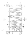
- a configuration of a dust collector 1 according to an embodiment of the present invention will be described below with reference to FIG. 1 and FIG. 2 .
- the dust collector 1 is, for example, installed in an exhaust gas treatment facility, which is provided inside a flue located on the downstream side of an industrial combustion facility such as a coal- or heavy oil-fired power generation plant or an incinerator.
- the dust collector 1 can be also used for a filter for air cleaning facilities (an air conditioning filter for a clean room, a filter for removing a virus, and the like, for example), and the like as well as for the industrial combustion facilities.
- the dust collector 1 includes a discharge electrode 2 that causes particulate material to be electrically charged and a collecting electrode 3 that is disposed facing the discharge electrode 2 in order to remove the particulate material, such as dust and mist.
- the discharge electrode 2 and the collecting electrode 3 are disposed inside a casing 4.
- the discharge electrode 2 has a mounting frame 5 and a discharge spike 18.
- the discharge spike 18 is disposed on the mounting frame 5 so as to form a spiny shape from the mounting frame 5 toward the collecting electrode 3.
- the mounting frame 5 is a linear member and is inclined with respect to the gas flow at the inlet portion.
- An upstream side of the gas flow in the dust collector 1 is positioned on a lower side in the gravity direction and a downstream side of the gas flow is positioned on an upper side in the gravity direction.
- the mounting frame 5 is formed of two mounting frames 5A and 5B combined with each other and self-stands on an electrode support member 14. More specifically, the two mounting frames 5A and 5B support the load of each other on the downstream side of the gas flow.
- the two mounting frames 5A and 5B are disposed so that the upstream side of the gas flow is wider than the downstream side of the gas flow.
- the two mounting frames 5A and 5B are disposed with the gap therebetween widened on the upstream side of the gas flow so that a space velocity becomes from 1 m/s to 4 m/s, for example.
- a shape formed by the plurality of mounting frames 5A and 5B combined with each other is a triangular prism. A bottom portion of the triangular prism on the upstream side of the gas flow is opened, and the mounting frames 5A and 5B are provided on side surfaces of the triangular prism.
- the collecting electrode 3 has a planar member 6 formed of a wire mesh or the like, and is disposed facing the discharge electrode 2.
- the planar member 6 of the collecting electrode 3 is a member having an opening and having conductivity, and is a wire mesh or a punching metal, for example.
- the planar member 6 is inclined with respect to the gas flow at the inlet portion.
- the collecting electrode 3 is formed of two planar members 6 combined with each other and self-stands on the support member.
- the two sheets of the planar members 6 support the load of each other on the downstream side of the gas flow.
- the two sheets of the planar members 6 are disposed so that the upstream side of the gas flow is wider than the downstream side of the gas flow.
- the collecting electrode 3 is positioned above the discharge electrode 2 so as to cover the discharge electrode 2, the discharge electrode 2 and the collecting electrode 3 are separated and electrically insulated from each other.
- the electrode support member 14 penetrates the casing 4 and is connected to an insulator 16 housed in an insulator room 17. In order to avoid leak of gas flowing in the casing 4, the electrode support member 14 is covered by a cylindrical member 20, for example, in the outside of the casing 4, and the end portion of the cylindrical member 20 is closed by the insulator room 17.
- the discharge electrode 2 is connected to a high voltage power supply (not illustrated) via the insulator 16 fixed to the casing 4 and the electrode support member 14. As a result of the high voltage being applied to the discharge electrode 2, corona discharge is generated by the discharge electrode 2. The corona discharge causes the particulate material contained in the exhaust gas to be ionized. Then, the ionized particulate material is collected by the collecting electrode 3.
- FIG. 1 illustrates an example in which a filter material 7 is provided in the dust collector 1, only the collecting electrode 3 may be disposed without the filter material 7.
- the dust collector 1 further include the filter material 7 disposed on a surface side of the collecting electrode 3 opposite to a surface of collecting electrode 3 facing the discharge electrode 2 as illustrated in FIG. 1 .
- the filter material 7 is a middle efficiency particulate air filter or the like, for example.
- the filter material 7 it is possible to enhance the overall dust-collecting efficiency of the dust collector 1.
- the filter material 7 have a specification that provides a finer mesh than that of the wire mesh.
- a material property of the filter material 7 is not particularly limited.
- the particulate material contained in the exhaust gas is ionized, and the ionized particulate material is collected by the collecting electrode 3.
- the two mounting frames 5 of the discharge electrode 2 support the load of each other on the downstream side of the gas flow and the two mounting frames 5 are disposed so that the upstream side of the gas flow is wider than the downstream side of the gas flow, the discharge electrode 2 can self-stand, being supported only from below and there is no need to support the discharge electrode 2 on an upper side thereof.
- the mounting frames 5 are inclined with respect to the flow direction of the gas flow and the upstream side of the gas flow is wider, it is possible to suppress an increase of the flow velocity in the gas inflow portion.
- the planar member 6 of the collecting electrode 3 is inclined with respect to the gas flow of the inlet portion, the ionized particulate material reliably penetrates the collecting electrode 3, regardless of being on the upstream side or the downstream side of the gas flow.
- the planar members 6 of the collecting electrode 3 support the load of each other on the downstream side of the gas flow and the two sheets of the planar members 6 are disposed so that the upstream side of the gas flow is wider than the downstream side of the gas flow, the planar members 6 can self-stand, being supported only from below, and there is no need to support the planar members 6 on an upper side thereof. Moreover, as the planar members 6 are inclined with respect to the flow direction of the gas flow and the upstream side of the gas flow is wider, it is possible to suppress an increase of the flow velocity in the gas inflow portion.
- a planar member 22 connects the collecting electrode 3 and the casing 4, and/or planar member 22 connects the collecting electrodes 3 adjacent to each other. Accordingly, the gap between the collecting electrode 3 and the casing 4 and/or the gap between the collecting electrodes adjacent to each other is closed by the planar member 22, and the gas flow in the casing 4 passes between the two planar members 6 combined with each other on the downstream side of the gas flow, thus preventing gas from flowing into other portions.
- the present invention is not limited to this example.
- the shape in the vertical cross section of the mounting frame 5 of the discharge electrode 2 and the shape in the vertical cross section of the planar member 6 of the collecting electrode 3 may be polygonal (trapezoidal, pentagonal, or the like, for example) other than triangular, for example.
- an electric field forming electrode 24 is disposed on a surface opposite to the surface having the collecting electrode 3 disposed thereon with respect to the filter material 7.
- the electric field forming electrode 24 is disposed separate from the filter material 7, and voltage is applied to the electric field forming electrode 24. Note that as the power supply of the electric field forming electrode 24, the same power supply for the discharge electrode 2 may be used.
- the electric field forming electrode 24 is a linear member similar to the mounting frame 5 of the discharge electrode 2.
- the electric field forming electrode 24 does not have a spike called discharge spike, unlike the discharge electrode 2.
- the electric field forming electrode 24 faces the filter material 7 and is inclined with respect to the gas flow at the inlet portion.
- the electric field forming electrode 24 is formed of two frames 24A and 24B combined with each other and is hung from an electrode support member 25. That is, the two frames 24A and 24B are connected to each other on the upstream side of the gas flow, and connected to the electrode support member 25 on the downstream side of the gas flow.
- the discharge electrode 2 is disposed on only the lower side of the collecting electrode 3, the present invention is not limited to this example.
- the discharge electrode 2 may be disposed on the both sides including the upper side and the lower side of the collecting electrode 3.
- the discharge electrode 2 disposed on the upper side of the collecting electrode 3 also has the mounting frame 5 and the discharge spike 18, similarly to the above-described discharge electrode 2 disposed on the lower side of the collecting electrode 3.
- the discharge electrode 2 disposed on the upper side is formed of two mounting frames 5C and 5D combined with each other and is hung from an electrode support member 26.
- the two mounting frames 5C and 5D are connected to each other on the upstream side of the gas flow.
- discharge space is formed on the both sides of the collecting electrode 3, thus enhancing dust-collecting efficiency.
- only one stage of dust collector 1 according to the present embodiment may be disposed in the exhaust gas treatment facility, or a plurality of stages of the dust collectors 1 may be disposed in series along the gas flow.
- a plurality of stages of dust collectors 1 is disposed in series along the gas flow, thus enhancing dust-collecting efficiency.
- the configurations of the discharge electrode 2 and the collecting electrode 3 are not limited to the forms described above. That is, the discharge electrode 2 and the collecting electrode 3 do not have to be inclined with respect to the gas flow direction, but may be disposed in parallel with the gas flow direction, as illustrated in FIG. 5 and FIG. 6 . Then, as illustrated in FIG. 5 , the filter material 7 may be provided and the electric field forming electrode 24 may be provided on the downstream side of the gas flow relative to the collecting electrode 3. As illustrated in FIG. 6 , the discharge electrode 2 may be disposed on the downstream side of the gas flow relative to the collecting electrode 3.
- the present invention is not limited to this example.
- the longitudinal direction of the mounting frame 5 and the planar member 6 may be disposed in a direction parallel to the installation surface of the dust collector 1, that is, in the horizontal direction, and the mounting frame 5 and the planar member 6 may be fixed to the support member in the cantilever manner.
- the gas flow in the casing 4 is a horizontal flow.
- the upstream side of the gas flow in the dust collector 1 may be positioned on the upper side in the gravity direction and the downstream side of the gas flow may be positioned on the lower side in the gravity direction.
- the mounting frame 5 is formed of two mounting frames 5A and 5B combined with each other and is hung from an electrode support member 27.
- the mounting frame 5 is disposed so that the upstream side of the gas flow is wider than the downstream side of the gas flow. That is, the two mounting frames 5A and 5B are connected to each other on the downstream side of the gas flow, and the cross-sectional shape is maintained, whereby there is no need to support the mounting frames 5A and 5B on the lower side thereof.
- the two planar members 6 of the collecting electrode 3 are connected to each other on the downstream side of the gas flow, and there is no need to support the planar members 6 on the lower side thereof.
- the filter material 7 illustrated in FIG. 7 is provided, on the back side thereof, with a support member such as a wire mesh to avoid falling.
- a support member such as a wire mesh to avoid falling.
- FIG. 7 the example in which the filter material 7 is provided has been described.
- the present modified example can be further applied to the example in which the electric field forming electrode 24 is disposed, the example in which the filter material 7 is not disposed and only the collecting electrode 3 is disposed, or the example in which the filter material 7 is not disposed and the discharge electrode 2 is further disposed on the back side of the collecting electrode 3, which have been described above.
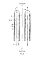
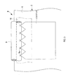
- the water washing unit 8 includes a water spraying unit 9 that is provided along the planar member 6 of the collecting electrode 3 and has a plurality of holes 9a through which water is sprayed downward, and a flat plate 10 that is provided on the lower portion of the water spraying unit 9 along the planar member 6 to receive water sprayed from the water spraying unit 9 and to allow water to flow toward the planar member 6.
- the water washing unit 9 is a tubular member, for example, and is disposed on the upper portion of the planar member 6.
- the plurality of holes 9a is formed on a tube wall of the water spraying unit 9 along the tube axis direction. Water is sprayed downward from the holes 9a.
- water sprayed downward from the plurality of holes 9a of the water spraying unit 9 hits the flat plate 10 to be diffused, and then flows toward the planar member 6 of the collecting electrode 3. Therefore, as compared with the case in which water is sprayed directly from the water spraying unit 9 toward the planar member 6 of the collecting electrode 3, water can be made flow equally onto the surface of the planar member 6 of the collecting electrode 3 to form a liquid film, thus allowing the collecting electrode 3 to be washed equally.
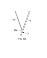
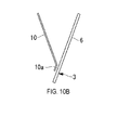
- an end portion 10a of the flat plate 10 on the planar member 6 side may have a linear cross section, as illustrated in FIG. 8 or FIG. 10A , or the end portion 10a on the planar member 6 side may be machined to bend downward or upward.
- FIG. 10 B and FIG. 10D illustrate examples in which the end portion 10a is bent downward
- FIG. 10C illustrates an example in which the bent portion is rounded.
- FIG. 10D illustrates an example in which the end portion 10a is bent upward so as to form a weir. Accordingly, water can be made flow more equally toward the planar member 6 of the collecting electrode 3.
- one water spraying unit 9 may be disposed to be shared in the upper portions of the two planar members 6 of the collecting electrode 3.
- two flat plates 10 are disposed for one water spraying unit 9 so as to correspond to the respective two planar members 6.
- at least two rows of holes 9a are formed in parallel with each other so as to correspond to the respective flat plates 10. Accordingly, when the electric field forming electrode 24 or the discharge electrode 2 is disposed above the collecting electrode 3, as illustrated in FIG. 3 and FIG. 4 , the water spraying unit 9 can be separated from the electric field forming electrode 24 or the discharge electrode 2 disposed above the collecting electrode 3, thus preventing occurrence of discharge between the water spraying unit 9 and the electric field forming electrode 24 or the discharge electrode 2.
- a running water board 31 may be disposed corresponding to one water spraying unit 9 disposed to be shared on the upper portion of the two planar members 6 of the collecting electrode 3.
- the running water board 31 is provided above the water spraying unit 9.
- the upper portion of the running water board 31 is a semi-cylinder 31a, and the lower portion thereof is formed of flat plates 31 b in parallel with each other.
- water washing unit 8 water sprayed upward from the plurality of holes 9a of the water spraying unit 9 hits the semi-cylinder 31a of the running water board 31 to be diffused. Thereafter, the water flows on the two flat plates 31b forming a liquid film, and then flows toward the planar members 6 of the collecting electrode 3.
- water can be made flow equally onto the surface of the planar members 6 of the collecting electrode 3, thus allowing the collecting electrode 3 to be washed equally.
- the water spraying unit 9 can be separated from the electric field forming electrode 24 or the discharge electrode 2 disposed above the collecting electrode 3, thus preventing occurrence of discharge between the water spraying unit 9 and the electric field forming electrode 24 or the discharge electrode 2.
- two rows of holes may be provided horizontally on the water spraying unit 9 so as to spray water in the horizontal direction, or one row of holes may be provided on the topmost portion of the water spraying unit 9 so as to spray water only in the directly-above direction in order to form a liquid film.
- the upper portion of the running water board 31 may be formed by a bent plate 31 c and, in this case, the running water board 31 is disposed so that the bent portion of the bent plate 31 c is positioned at the apex portion.
- the two flat plates 31 b of the running water board 31 do not have to be parallel with each other as long as a liquid film can be guided to the collecting electrode 3, and may be provided to be widened downward, for example. Moreover, the lower end portion of the flat plate 31b may be machined to bend inward, for example.
- the configurations of the discharge electrode 2 and the collecting electrode 3 are not limited to the case of the dust collector 1 having the above-described forms. That is, the discharge electrode 2 and the collecting electrode 3 do not have to be inclined with respect to the gas flow direction, but may be disposed in parallel with the gas flow direction, as illustrated in FIG. 5 and FIG. 6 .
- the water washing unit 8 is disposed so that the lower end portions of the two flat plates 31b of the running water board 31 are positioned on the respective upper ends of the two collecting electrodes 3 in parallel with each other. Accordingly, as compared with the case in which one water spraying unit 9 is provided for each collecting electrode 3, the number of water spraying units 9 to be disposed can be reduced.
- the running water board 31 can block the gas flow and make gas flowing from the upstream side flow toward the collecting electrode 3.
- the water washing unit 8 may be configured to wash the discharge electrode 2 as well by spraying water from the upstream side in the direction of the gas flow.
- FIG. 1 illustrates the example in which a water washing unit 11 for washing the filter material 7 is further provided.
- the water washing units 8A and 8B and the water washing unit 11 A start washing at the same time, and the other washing units 8 and 11 stop washing. Then, washing by the water washing unit 8A and the water washing unit 11 A is stopped, and washing by the water washing units 8B and 8C and the water washing unit 11B is started next.
- the other washing units 8 and 11 are kept stopped.
- FIG. 1 illustrates the case in which one water washing unit 11 is provided for two filter materials 7, one water washing unit 11 may be disposed for one filter material 7.
- the dust collector 1 may include therein a plurality of ducts 13 separating, with partitions, each row of the collecting electrode 3 and the discharge electrode 2. Dampers 12 that can be opened and closed are disposed at the outlet of the ducts 13. Then, the operation for closing the damper 12 is performed when the collecting electrode 3 and the discharge electrode 2 are washed. When the damper 12 is closed, the gas does not pass the collecting electrode 3 positioned on the inner side of the closed damper 12. Thus, a liquid film can be formed securely on the surface of the planar member 6 of the collecting electrode 3 in the closed damper 12.
Landscapes
- Electrostatic Separation (AREA)
Applications Claiming Priority (2)
| Application Number | Priority Date | Filing Date | Title |
|---|---|---|---|
| JP2013052932 | 2013-02-07 | ||
| PCT/JP2014/052802 WO2014123202A1 (fr) | 2013-02-07 | 2014-02-06 | Appareil, système et procédé de collecte de poussière |
Publications (3)
| Publication Number | Publication Date |
|---|---|
| EP2954955A1 true EP2954955A1 (fr) | 2015-12-16 |
| EP2954955A4 EP2954955A4 (fr) | 2016-12-28 |
| EP2954955B1 EP2954955B1 (fr) | 2022-07-13 |
Family
ID=51299793
Family Applications (1)
| Application Number | Title | Priority Date | Filing Date |
|---|---|---|---|
| EP14749331.6A Active EP2954955B1 (fr) | 2013-02-07 | 2014-02-06 | Appareil, système et procédé de collecte de poussière |
Country Status (6)
| Country | Link |
|---|---|
| US (1) | US10071384B2 (fr) |
| EP (1) | EP2954955B1 (fr) |
| JP (1) | JP6367123B2 (fr) |
| CN (1) | CN104994960B (fr) |
| BR (1) | BR112015018756B1 (fr) |
| WO (1) | WO2014123202A1 (fr) |
Cited By (2)
| Publication number | Priority date | Publication date | Assignee | Title |
|---|---|---|---|---|
| CN106269256A (zh) * | 2016-08-10 | 2017-01-04 | 福建龙净环保股份有限公司 | 一种用于烟气净化的电除雾器 |
| CN112742602A (zh) * | 2021-01-19 | 2021-05-04 | 国电环境保护研究院有限公司 | 一种强化收尘的阴阳极模块 |
Families Citing this family (17)
| Publication number | Priority date | Publication date | Assignee | Title |
|---|---|---|---|---|
| US9827573B2 (en) * | 2014-09-11 | 2017-11-28 | University Of Washington | Electrostatic precipitator |
| JP6462416B2 (ja) * | 2015-02-27 | 2019-01-30 | 三菱日立パワーシステムズ環境ソリューション株式会社 | So3除去装置及び排ガス処理システム、並びに、so3除去方法 |
| US10357734B2 (en) * | 2015-10-30 | 2019-07-23 | Lg Electronics Inc. | Air freshener |
| EP3163203B1 (fr) * | 2015-10-30 | 2020-12-02 | LG Electronics Inc. | Rafraîchisseur d'air |
| WO2017078614A1 (fr) * | 2015-11-04 | 2017-05-11 | Blue Sky Engineering & Trading Pte Ltd | Précipitateur électrostatique |
| JP6752736B2 (ja) * | 2017-02-10 | 2020-09-09 | 三菱日立パワーシステムズ環境ソリューション株式会社 | 電気集塵装置 |
| CN107477641A (zh) * | 2017-09-19 | 2017-12-15 | 东北师范大学 | 基于物联网的楼宇排烟伞式静电净化处理系统 |
| JP7109194B2 (ja) * | 2018-01-15 | 2022-07-29 | 三菱重工パワー環境ソリューション株式会社 | 電気集塵装置 |
| CN108548697B (zh) * | 2018-05-07 | 2024-01-02 | 中国林业科学研究院 | 降尘收集器 |
| CN112512695B (zh) * | 2018-08-01 | 2023-08-11 | 三菱重工动力环保有限公司 | 电集尘装置 |
| US11471816B2 (en) | 2019-03-11 | 2022-10-18 | Karim Salehpoor | Pollutant capturer and mobilizer |
| DE102019108207A1 (de) * | 2019-03-29 | 2020-10-01 | Bayerische Motoren Werke Aktiengesellschaft | Luftfiltervorrichtung für ein Kraftfahrzeug und Kraftfahrzeug mit einer solchen |
| CN111947239B (zh) * | 2019-05-14 | 2022-06-21 | 斗山重工业建设有限公司 | 空调系统用集尘装置及包含该集尘装置的空调装置 |
| EP4007658A1 (fr) | 2019-08-01 | 2022-06-08 | Infinite Cooling Inc. | Systèmes et procédés pour collecter un fluide contenu dans un flux de gaz |
| WO2021021370A1 (fr) | 2019-08-01 | 2021-02-04 | Infinite Cooling Inc. | Panneaux destinés à être utilisés dans la collecte de fluide à partir d'un flux de gaz |
| EP4110528A1 (fr) | 2020-02-27 | 2023-01-04 | Infinite Cooling Inc. | Systèmes, dispositifs, et procédés pour collecter des espèces à partir d'un courant de gaz |
| CN114377857B (zh) * | 2020-10-21 | 2025-04-11 | 上海必修福企业管理有限公司 | 电场单元组件和电场装置 |
Family Cites Families (32)
| Publication number | Priority date | Publication date | Assignee | Title |
|---|---|---|---|---|
| US2700429A (en) * | 1952-10-15 | 1955-01-25 | Research Corp | Electrical precipitator |
| GB1306388A (fr) * | 1970-05-12 | 1973-02-07 | ||
| JPS47770U (fr) * | 1971-01-12 | 1972-08-05 | ||
| US4126434A (en) * | 1975-09-13 | 1978-11-21 | Hara Keiichi | Electrostatic dust precipitators |
| JPS5310179A (en) * | 1976-07-14 | 1978-01-30 | Nippon Earo Piyuuru Kk | Wet wall forming method |
| JPS5925625B2 (ja) * | 1978-07-21 | 1984-06-19 | 石川島播磨重工業株式会社 | 水膜式電気集じん機の水膜形成装置 |
| JPS553885A (en) * | 1978-10-16 | 1980-01-11 | Ishikawajima Harima Heavy Ind Co Ltd | Particle trapping device |
| JPS58107151U (ja) * | 1981-12-29 | 1983-07-21 | 中部電力株式会社 | 水膜式電気集じん装置の給水装置 |
| US4521229A (en) * | 1983-11-01 | 1985-06-04 | Combustion Engineering, Inc. | Tubular discharge electrode for electrostatic precipitator |
| JPS6115750A (ja) * | 1984-06-30 | 1986-01-23 | Corona Giken Kogyo Kk | 排ガス浄化装置 |
| JPH0711102B2 (ja) * | 1986-11-05 | 1995-02-08 | 津田駒工業株式会社 | 空気噴射式織機の補助ノズル |
| SE463077B (sv) * | 1988-06-03 | 1990-10-08 | Boliden Contech Ab | Emissionselektrod |
| JP2902058B2 (ja) * | 1990-06-21 | 1999-06-07 | 三菱重工業株式会社 | ミストエリミネータ |
| DE4139474A1 (de) * | 1990-11-30 | 1992-06-04 | Toshiba Kawasaki Kk | Elektro-staubabscheideanlage |
| JP3388740B2 (ja) * | 1991-12-11 | 2003-03-24 | ヤマモト,ユージロー | ガス流体中の微粒子を捕獲するためのフィルタおよびこのフィルタを用いてガス流体中の微粒子を捕獲するための方法 |
| US5403383A (en) * | 1992-08-26 | 1995-04-04 | Jaisinghani; Rajan | Safe ionizing field electrically enhanced filter and process for safely ionizing a field of an electrically enhanced filter |
| CN2189003Y (zh) * | 1993-12-07 | 1995-02-08 | 周永贵 | 电收尘不锈钢极网 |
| JPH07265730A (ja) | 1994-03-29 | 1995-10-17 | Nippon Kayaku Co Ltd | 空気清浄脱臭装置 |
| US5549735C1 (en) * | 1994-06-09 | 2001-08-14 | Coppom Technologies | Electrostatic fibrous filter |
| JP3495482B2 (ja) * | 1995-11-20 | 2004-02-09 | 三菱重工業株式会社 | ダクト型湿式電気集塵装置 |
| JPH10244832A (ja) | 1997-03-03 | 1998-09-14 | Advance Innov:Kk | 車両用サンバイザー |
| US6497754B2 (en) * | 2001-04-04 | 2002-12-24 | Constantinos J. Joannou | Self ionizing pleated air filter system |
| JP2002361117A (ja) * | 2001-06-09 | 2002-12-17 | Ayumi Iijima | 電気集塵装置 |
| JP3973859B2 (ja) * | 2001-06-29 | 2007-09-12 | 松下エコシステムズ株式会社 | 電気集塵ユニット |
| JP2004167453A (ja) * | 2002-11-22 | 2004-06-17 | Mitsubishi Heavy Ind Ltd | 除塵装置 |
| US6790259B2 (en) | 2003-01-16 | 2004-09-14 | Blueair Ab | Method and device for cleaning a gaseous fluid using a conductive grid between charging head and filter |
| JP4339049B2 (ja) | 2003-08-29 | 2009-10-07 | 日新電機株式会社 | 排ガス処理方法及び排ガス処理装置 |
| JP4854270B2 (ja) * | 2005-10-31 | 2012-01-18 | 三菱重工メカトロシステムズ株式会社 | ガス浄化装置及び方法 |
| JP2008212846A (ja) * | 2007-03-05 | 2008-09-18 | Hitachi Plant Technologies Ltd | 湿式電気集塵装置の流水機構 |
| JP4894739B2 (ja) * | 2007-11-30 | 2012-03-14 | ダイキン工業株式会社 | 湿式電気集塵機 |
| CN101396677B (zh) * | 2008-11-05 | 2011-12-21 | 中冶京诚工程技术有限公司 | 极板冲洗装置及方法 |
| US8889079B2 (en) * | 2010-01-13 | 2014-11-18 | Efb, Inc. | Apparatus for removal of particles and VOC from an airstream |
-
2014
- 2014-02-06 WO PCT/JP2014/052802 patent/WO2014123202A1/fr not_active Ceased
- 2014-02-06 JP JP2014560807A patent/JP6367123B2/ja active Active
- 2014-02-06 US US14/765,753 patent/US10071384B2/en active Active
- 2014-02-06 CN CN201480007544.9A patent/CN104994960B/zh active Active
- 2014-02-06 BR BR112015018756-0A patent/BR112015018756B1/pt active IP Right Grant
- 2014-02-06 EP EP14749331.6A patent/EP2954955B1/fr active Active
Cited By (2)
| Publication number | Priority date | Publication date | Assignee | Title |
|---|---|---|---|---|
| CN106269256A (zh) * | 2016-08-10 | 2017-01-04 | 福建龙净环保股份有限公司 | 一种用于烟气净化的电除雾器 |
| CN112742602A (zh) * | 2021-01-19 | 2021-05-04 | 国电环境保护研究院有限公司 | 一种强化收尘的阴阳极模块 |
Also Published As
| Publication number | Publication date |
|---|---|
| WO2014123202A1 (fr) | 2014-08-14 |
| CN104994960A (zh) | 2015-10-21 |
| JP6367123B2 (ja) | 2018-08-01 |
| US10071384B2 (en) | 2018-09-11 |
| EP2954955A4 (fr) | 2016-12-28 |
| BR112015018756A2 (pt) | 2017-07-18 |
| BR112015018756B1 (pt) | 2022-01-25 |
| JPWO2014123202A1 (ja) | 2017-02-02 |
| EP2954955B1 (fr) | 2022-07-13 |
| US20150375237A1 (en) | 2015-12-31 |
| CN104994960B (zh) | 2019-01-11 |
Similar Documents
| Publication | Publication Date | Title |
|---|---|---|
| US10071384B2 (en) | Dust collector, dust collection system, and dust collection method | |
| KR100949455B1 (ko) | 집진 필터 및 이를 구비하는 전기집진장치 | |
| US9808809B2 (en) | Dust collector, electrode selection method for dust collector, and dust collection method | |
| DK2471602T3 (en) | Electrical shielding device for structures near high voltage parts of electrostatic precipitators | |
| KR102095316B1 (ko) | 세정장치를 구비한 2단 하전식 플라즈마 집진기 | |
| US11524305B2 (en) | Electrostatic precipitator apparatus | |
| US10751729B2 (en) | Electrostatic precipitor | |
| WO2008033190A1 (fr) | Système et dispositif de séparation de particules électrostatiques | |
| CN202366787U (zh) | 除尘系统及其静电除尘器 | |
| JP6390004B2 (ja) | 電気集塵装置 | |
| CN106955785B (zh) | 静电装置和油烟机 | |
| EP3453461A1 (fr) | Unité de purificateur d'air | |
| CN216878516U (zh) | 油雾净化机组 | |
| CN206604646U (zh) | 静电装置和油烟机 | |
| KR102786963B1 (ko) | 유지관리 보수가 용이한 수직조립식 전기 집진장치 | |
| JP2008006371A (ja) | 集塵装置 | |
| CN211600931U (zh) | 一种水帘式高压静电净化器 | |
| JP2001190982A (ja) | 電気集塵装置 | |
| FI129388B (en) | Air purification module, air purification system, air treatment unit and the use of an air purification module | |
| JP6788881B2 (ja) | 空気浄化機 | |
| CN201871422U (zh) | 静电油烟净化设备 | |
| CN212369822U (zh) | 一种高压平板式静电除烟雾装置 | |
| KR102484494B1 (ko) | 집진전극의 집진효율 및 세척효율을 증대시킨 전기집진장치 | |
| CN219463703U (zh) | 一种自清洁的静电式油雾净化器 | |
| CN102806144A (zh) | 油烟净化器 |
Legal Events
| Date | Code | Title | Description |
|---|---|---|---|
| PUAI | Public reference made under article 153(3) epc to a published international application that has entered the european phase |
Free format text: ORIGINAL CODE: 0009012 |
|
| 17P | Request for examination filed |
Effective date: 20150804 |
|
| AK | Designated contracting states |
Kind code of ref document: A1 Designated state(s): AL AT BE BG CH CY CZ DE DK EE ES FI FR GB GR HR HU IE IS IT LI LT LU LV MC MK MT NL NO PL PT RO RS SE SI SK SM TR |
|
| AX | Request for extension of the european patent |
Extension state: BA ME |
|
| RAP1 | Party data changed (applicant data changed or rights of an application transferred) |
Owner name: MITSUBISHI HITACHI POWER SYSTEMS ENVIRONMENTAL SOL |
|
| DAX | Request for extension of the european patent (deleted) | ||
| RIC1 | Information provided on ipc code assigned before grant |
Ipc: B03C 3/41 20060101AFI20160819BHEP Ipc: B03C 3/78 20060101ALI20160819BHEP Ipc: B03C 3/47 20060101ALI20160819BHEP Ipc: B03C 3/40 20060101ALI20160819BHEP Ipc: B03C 3/09 20060101ALI20160819BHEP |
|
| A4 | Supplementary search report drawn up and despatched |
Effective date: 20161128 |
|
| RIC1 | Information provided on ipc code assigned before grant |
Ipc: B03C 3/40 20060101ALI20161122BHEP Ipc: B03C 3/41 20060101AFI20161122BHEP Ipc: B03C 3/78 20060101ALI20161122BHEP Ipc: B03C 3/47 20060101ALI20161122BHEP Ipc: B03C 3/09 20060101ALI20161122BHEP |
|
| RAP1 | Party data changed (applicant data changed or rights of an application transferred) |
Owner name: MITSUBISHI POWER ENVIRONMENTAL SOLUTIONS, LTD. |
|
| STAA | Information on the status of an ep patent application or granted ep patent |
Free format text: STATUS: EXAMINATION IS IN PROGRESS |
|
| 17Q | First examination report despatched |
Effective date: 20201120 |
|
| RAP3 | Party data changed (applicant data changed or rights of an application transferred) |
Owner name: MITSUBISHI HEAVY INDUSTRIES POWER ENVIRONMENTAL SOLUTIONS, LTD. |
|
| GRAP | Despatch of communication of intention to grant a patent |
Free format text: ORIGINAL CODE: EPIDOSNIGR1 |
|
| STAA | Information on the status of an ep patent application or granted ep patent |
Free format text: STATUS: GRANT OF PATENT IS INTENDED |
|
| INTG | Intention to grant announced |
Effective date: 20220318 |
|
| RIN1 | Information on inventor provided before grant (corrected) |
Inventor name: TANAKA, TAKAO Inventor name: KATO, MASAYA Inventor name: TOMIMATSU, KAZUTAKA Inventor name: KOJIMA, KATSUHISA |
|
| GRAS | Grant fee paid |
Free format text: ORIGINAL CODE: EPIDOSNIGR3 |
|
| GRAA | (expected) grant |
Free format text: ORIGINAL CODE: 0009210 |
|
| STAA | Information on the status of an ep patent application or granted ep patent |
Free format text: STATUS: THE PATENT HAS BEEN GRANTED |
|
| AK | Designated contracting states |
Kind code of ref document: B1 Designated state(s): AL AT BE BG CH CY CZ DE DK EE ES FI FR GB GR HR HU IE IS IT LI LT LU LV MC MK MT NL NO PL PT RO RS SE SI SK SM TR |
|
| REG | Reference to a national code |
Ref country code: GB Ref legal event code: FG4D |
|
| REG | Reference to a national code |
Ref country code: CH Ref legal event code: EP |
|
| REG | Reference to a national code |
Ref country code: IE Ref legal event code: FG4D |
|
| REG | Reference to a national code |
Ref country code: DE Ref legal event code: R096 Ref document number: 602014084287 Country of ref document: DE |
|
| REG | Reference to a national code |
Ref country code: AT Ref legal event code: REF Ref document number: 1503980 Country of ref document: AT Kind code of ref document: T Effective date: 20220815 |
|
| REG | Reference to a national code |
Ref country code: NO Ref legal event code: T2 Effective date: 20220713 |
|
| REG | Reference to a national code |
Ref country code: LT Ref legal event code: MG9D |
|
| REG | Reference to a national code |
Ref country code: NL Ref legal event code: MP Effective date: 20220713 |
|
| PG25 | Lapsed in a contracting state [announced via postgrant information from national office to epo] |
Ref country code: SE Free format text: LAPSE BECAUSE OF FAILURE TO SUBMIT A TRANSLATION OF THE DESCRIPTION OR TO PAY THE FEE WITHIN THE PRESCRIBED TIME-LIMIT Effective date: 20220713 Ref country code: RS Free format text: LAPSE BECAUSE OF FAILURE TO SUBMIT A TRANSLATION OF THE DESCRIPTION OR TO PAY THE FEE WITHIN THE PRESCRIBED TIME-LIMIT Effective date: 20220713 Ref country code: PT Free format text: LAPSE BECAUSE OF FAILURE TO SUBMIT A TRANSLATION OF THE DESCRIPTION OR TO PAY THE FEE WITHIN THE PRESCRIBED TIME-LIMIT Effective date: 20221114 Ref country code: NL Free format text: LAPSE BECAUSE OF FAILURE TO SUBMIT A TRANSLATION OF THE DESCRIPTION OR TO PAY THE FEE WITHIN THE PRESCRIBED TIME-LIMIT Effective date: 20220713 Ref country code: LV Free format text: LAPSE BECAUSE OF FAILURE TO SUBMIT A TRANSLATION OF THE DESCRIPTION OR TO PAY THE FEE WITHIN THE PRESCRIBED TIME-LIMIT Effective date: 20220713 Ref country code: LT Free format text: LAPSE BECAUSE OF FAILURE TO SUBMIT A TRANSLATION OF THE DESCRIPTION OR TO PAY THE FEE WITHIN THE PRESCRIBED TIME-LIMIT Effective date: 20220713 Ref country code: FI Free format text: LAPSE BECAUSE OF FAILURE TO SUBMIT A TRANSLATION OF THE DESCRIPTION OR TO PAY THE FEE WITHIN THE PRESCRIBED TIME-LIMIT Effective date: 20220713 Ref country code: ES Free format text: LAPSE BECAUSE OF FAILURE TO SUBMIT A TRANSLATION OF THE DESCRIPTION OR TO PAY THE FEE WITHIN THE PRESCRIBED TIME-LIMIT Effective date: 20220713 |
|
| REG | Reference to a national code |
Ref country code: AT Ref legal event code: MK05 Ref document number: 1503980 Country of ref document: AT Kind code of ref document: T Effective date: 20220713 |
|
| PG25 | Lapsed in a contracting state [announced via postgrant information from national office to epo] |
Ref country code: PL Free format text: LAPSE BECAUSE OF FAILURE TO SUBMIT A TRANSLATION OF THE DESCRIPTION OR TO PAY THE FEE WITHIN THE PRESCRIBED TIME-LIMIT Effective date: 20220713 Ref country code: IS Free format text: LAPSE BECAUSE OF FAILURE TO SUBMIT A TRANSLATION OF THE DESCRIPTION OR TO PAY THE FEE WITHIN THE PRESCRIBED TIME-LIMIT Effective date: 20221113 Ref country code: HR Free format text: LAPSE BECAUSE OF FAILURE TO SUBMIT A TRANSLATION OF THE DESCRIPTION OR TO PAY THE FEE WITHIN THE PRESCRIBED TIME-LIMIT Effective date: 20220713 Ref country code: GR Free format text: LAPSE BECAUSE OF FAILURE TO SUBMIT A TRANSLATION OF THE DESCRIPTION OR TO PAY THE FEE WITHIN THE PRESCRIBED TIME-LIMIT Effective date: 20221014 |
|
| REG | Reference to a national code |
Ref country code: DE Ref legal event code: R097 Ref document number: 602014084287 Country of ref document: DE |
|
| PG25 | Lapsed in a contracting state [announced via postgrant information from national office to epo] |
Ref country code: SM Free format text: LAPSE BECAUSE OF FAILURE TO SUBMIT A TRANSLATION OF THE DESCRIPTION OR TO PAY THE FEE WITHIN THE PRESCRIBED TIME-LIMIT Effective date: 20220713 Ref country code: RO Free format text: LAPSE BECAUSE OF FAILURE TO SUBMIT A TRANSLATION OF THE DESCRIPTION OR TO PAY THE FEE WITHIN THE PRESCRIBED TIME-LIMIT Effective date: 20220713 Ref country code: DK Free format text: LAPSE BECAUSE OF FAILURE TO SUBMIT A TRANSLATION OF THE DESCRIPTION OR TO PAY THE FEE WITHIN THE PRESCRIBED TIME-LIMIT Effective date: 20220713 Ref country code: CZ Free format text: LAPSE BECAUSE OF FAILURE TO SUBMIT A TRANSLATION OF THE DESCRIPTION OR TO PAY THE FEE WITHIN THE PRESCRIBED TIME-LIMIT Effective date: 20220713 Ref country code: AT Free format text: LAPSE BECAUSE OF FAILURE TO SUBMIT A TRANSLATION OF THE DESCRIPTION OR TO PAY THE FEE WITHIN THE PRESCRIBED TIME-LIMIT Effective date: 20220713 |
|
| PLBE | No opposition filed within time limit |
Free format text: ORIGINAL CODE: 0009261 |
|
| STAA | Information on the status of an ep patent application or granted ep patent |
Free format text: STATUS: NO OPPOSITION FILED WITHIN TIME LIMIT |
|
| PG25 | Lapsed in a contracting state [announced via postgrant information from national office to epo] |
Ref country code: SK Free format text: LAPSE BECAUSE OF FAILURE TO SUBMIT A TRANSLATION OF THE DESCRIPTION OR TO PAY THE FEE WITHIN THE PRESCRIBED TIME-LIMIT Effective date: 20220713 Ref country code: EE Free format text: LAPSE BECAUSE OF FAILURE TO SUBMIT A TRANSLATION OF THE DESCRIPTION OR TO PAY THE FEE WITHIN THE PRESCRIBED TIME-LIMIT Effective date: 20220713 |
|
| 26N | No opposition filed |
Effective date: 20230414 |
|
| PG25 | Lapsed in a contracting state [announced via postgrant information from national office to epo] |
Ref country code: AL Free format text: LAPSE BECAUSE OF FAILURE TO SUBMIT A TRANSLATION OF THE DESCRIPTION OR TO PAY THE FEE WITHIN THE PRESCRIBED TIME-LIMIT Effective date: 20220713 |
|
| PG25 | Lapsed in a contracting state [announced via postgrant information from national office to epo] |
Ref country code: SI Free format text: LAPSE BECAUSE OF FAILURE TO SUBMIT A TRANSLATION OF THE DESCRIPTION OR TO PAY THE FEE WITHIN THE PRESCRIBED TIME-LIMIT Effective date: 20220713 |
|
| REG | Reference to a national code |
Ref country code: DE Ref legal event code: R119 Ref document number: 602014084287 Country of ref document: DE |
|
| PG25 | Lapsed in a contracting state [announced via postgrant information from national office to epo] |
Ref country code: MC Free format text: LAPSE BECAUSE OF FAILURE TO SUBMIT A TRANSLATION OF THE DESCRIPTION OR TO PAY THE FEE WITHIN THE PRESCRIBED TIME-LIMIT Effective date: 20220713 |
|
| REG | Reference to a national code |
Ref country code: CH Ref legal event code: PL |
|
| REG | Reference to a national code |
Ref country code: BE Ref legal event code: MM Effective date: 20230228 |
|
| PG25 | Lapsed in a contracting state [announced via postgrant information from national office to epo] |
Ref country code: LU Free format text: LAPSE BECAUSE OF NON-PAYMENT OF DUE FEES Effective date: 20230206 Ref country code: LI Free format text: LAPSE BECAUSE OF NON-PAYMENT OF DUE FEES Effective date: 20230228 Ref country code: CH Free format text: LAPSE BECAUSE OF NON-PAYMENT OF DUE FEES Effective date: 20230228 |
|
| REG | Reference to a national code |
Ref country code: IE Ref legal event code: MM4A |
|
| PG25 | Lapsed in a contracting state [announced via postgrant information from national office to epo] |
Ref country code: IT Free format text: LAPSE BECAUSE OF FAILURE TO SUBMIT A TRANSLATION OF THE DESCRIPTION OR TO PAY THE FEE WITHIN THE PRESCRIBED TIME-LIMIT Effective date: 20220713 Ref country code: IE Free format text: LAPSE BECAUSE OF NON-PAYMENT OF DUE FEES Effective date: 20230206 Ref country code: FR Free format text: LAPSE BECAUSE OF NON-PAYMENT OF DUE FEES Effective date: 20230228 Ref country code: DE Free format text: LAPSE BECAUSE OF NON-PAYMENT OF DUE FEES Effective date: 20230901 |
|
| PG25 | Lapsed in a contracting state [announced via postgrant information from national office to epo] |
Ref country code: BE Free format text: LAPSE BECAUSE OF NON-PAYMENT OF DUE FEES Effective date: 20230228 |
|
| PG25 | Lapsed in a contracting state [announced via postgrant information from national office to epo] |
Ref country code: BG Free format text: LAPSE BECAUSE OF FAILURE TO SUBMIT A TRANSLATION OF THE DESCRIPTION OR TO PAY THE FEE WITHIN THE PRESCRIBED TIME-LIMIT Effective date: 20220713 |
|
| PG25 | Lapsed in a contracting state [announced via postgrant information from national office to epo] |
Ref country code: BG Free format text: LAPSE BECAUSE OF FAILURE TO SUBMIT A TRANSLATION OF THE DESCRIPTION OR TO PAY THE FEE WITHIN THE PRESCRIBED TIME-LIMIT Effective date: 20220713 |
|
| PG25 | Lapsed in a contracting state [announced via postgrant information from national office to epo] |
Ref country code: CY Free format text: LAPSE BECAUSE OF FAILURE TO SUBMIT A TRANSLATION OF THE DESCRIPTION OR TO PAY THE FEE WITHIN THE PRESCRIBED TIME-LIMIT; INVALID AB INITIO Effective date: 20140206 |
|
| PG25 | Lapsed in a contracting state [announced via postgrant information from national office to epo] |
Ref country code: HU Free format text: LAPSE BECAUSE OF FAILURE TO SUBMIT A TRANSLATION OF THE DESCRIPTION OR TO PAY THE FEE WITHIN THE PRESCRIBED TIME-LIMIT; INVALID AB INITIO Effective date: 20140206 |
|
| PG25 | Lapsed in a contracting state [announced via postgrant information from national office to epo] |
Ref country code: TR Free format text: LAPSE BECAUSE OF FAILURE TO SUBMIT A TRANSLATION OF THE DESCRIPTION OR TO PAY THE FEE WITHIN THE PRESCRIBED TIME-LIMIT Effective date: 20220713 |
|
| PGFP | Annual fee paid to national office [announced via postgrant information from national office to epo] |
Ref country code: GB Payment date: 20260106 Year of fee payment: 13 |
|
| PGFP | Annual fee paid to national office [announced via postgrant information from national office to epo] |
Ref country code: NO Payment date: 20260211 Year of fee payment: 13 |