EP2955132A1 - Verschleißplatte, Verfahren zu dessen Herstellung und Massenguthandhabungsvorrichtung - Google Patents
Verschleißplatte, Verfahren zu dessen Herstellung und Massenguthandhabungsvorrichtung Download PDFInfo
- Publication number
- EP2955132A1 EP2955132A1 EP14171772.8A EP14171772A EP2955132A1 EP 2955132 A1 EP2955132 A1 EP 2955132A1 EP 14171772 A EP14171772 A EP 14171772A EP 2955132 A1 EP2955132 A1 EP 2955132A1
- Authority
- EP
- European Patent Office
- Prior art keywords
- wear plate
- base plate
- abrasion
- plate
- resistant element
- Prior art date
- Legal status (The legal status is an assumption and is not a legal conclusion. Google has not performed a legal analysis and makes no representation as to the accuracy of the status listed.)
- Withdrawn
Links
Images
Classifications
-
- B—PERFORMING OPERATIONS; TRANSPORTING
- B65—CONVEYING; PACKING; STORING; HANDLING THIN OR FILAMENTARY MATERIAL
- B65G—TRANSPORT OR STORAGE DEVICES, e.g. CONVEYORS FOR LOADING OR TIPPING, SHOP CONVEYOR SYSTEMS OR PNEUMATIC TUBE CONVEYORS
- B65G11/00—Chutes
- B65G11/16—Interior surfaces; Linings
- B65G11/166—Interior surfaces; Linings for bulk
-
- B—PERFORMING OPERATIONS; TRANSPORTING
- B65—CONVEYING; PACKING; STORING; HANDLING THIN OR FILAMENTARY MATERIAL
- B65D—CONTAINERS FOR STORAGE OR TRANSPORT OF ARTICLES OR MATERIALS, e.g. BAGS, BARRELS, BOTTLES, BOXES, CANS, CARTONS, CRATES, DRUMS, JARS, TANKS, HOPPERS, FORWARDING CONTAINERS; ACCESSORIES, CLOSURES, OR FITTINGS THEREFOR; PACKAGING ELEMENTS; PACKAGES
- B65D90/00—Component parts, details or accessories for large containers
- B65D90/02—Wall construction
- B65D90/04—Linings
- B65D90/041—Rigid liners fixed to the container
- B65D90/044—Rigid liners fixed to the container fixed or supported over substantially the whole interface
- B65D90/045—Rigid liners fixed to the container fixed or supported over substantially the whole interface the liners being in the form of tiles or panels
-
- B—PERFORMING OPERATIONS; TRANSPORTING
- B65—CONVEYING; PACKING; STORING; HANDLING THIN OR FILAMENTARY MATERIAL
- B65G—TRANSPORT OR STORAGE DEVICES, e.g. CONVEYORS FOR LOADING OR TIPPING, SHOP CONVEYOR SYSTEMS OR PNEUMATIC TUBE CONVEYORS
- B65G2203/00—Indexing code relating to control or detection of the articles or the load carriers during conveying
- B65G2203/04—Detection means
- B65G2203/042—Sensors
-
- B—PERFORMING OPERATIONS; TRANSPORTING
- B65—CONVEYING; PACKING; STORING; HANDLING THIN OR FILAMENTARY MATERIAL
- B65G—TRANSPORT OR STORAGE DEVICES, e.g. CONVEYORS FOR LOADING OR TIPPING, SHOP CONVEYOR SYSTEMS OR PNEUMATIC TUBE CONVEYORS
- B65G2207/00—Indexing codes relating to constructional details, configuration and additional features of a handling device, e.g. Conveyors
- B65G2207/48—Wear protection or indication features
Definitions
- the present invention relates to material handling equipment.
- the invention relates to wear plates used in belt conveyor chutes and silos for bulk material handling.
- Wear plates are widely used in bulk material handling applications in process industries and in the logistic chain thereof. Wear plates are particularly used to protect machines and structures from wear that is caused by transferred material hitting and sliding on the structures for transporting bulk material, for example chutes, skirt boards and various silos and bins.
- CN 201586533 discloses such a wear plate including highly abrasion-resistant materials, such as ceramics.
- Typical application locations for wear plates include mines, ports and terminals, refineries, steel mills, power stations and other industrial plants where bulk materials are handled.
- the life span of wear plates varies significantly depending on the hostility of the application environment. Due to said high variance, it is often difficult if not impossible to determine, how long a particular wear plate may be used until it has to be replaced. So far the problem of determining the remaining life span of a wear plate has been solved by visual inspection. Since wear plates are often installed in locations that are very difficult to reach or even see, the inspection is expensive and sometimes dangerous. In more severe cases, production facilities may even be shut down for inspection.
- the aim of the present invention is achieved with aid of a novel wear plate for a bulk material handling device.
- the wear plate includes a substrate and an abrasion-resistant element, which is superposed on the substrate.
- An electrical conductor is arranged between the substrate and abrasion-resistant element so as to indicate whether or not the abrasion-resistant element is intact thus indicating the remaining life span.
- the wear element according to the present invention is characterized by the characterizing portion of claim 1.
- the aim is on the other hand achieved with aid of a bulk material handling device including such a wear plate.
- any disturbance in the conductivity of the conductor indicates damage in the abrasion-resistant element, whereby it may be concluded that the wear plate has reached the end of its life span.
- the integrated electrical conductor acting as a sensor, the condition information of the wear is made available and easily accessible outside of the bulk handling device or remotely from a control room of the plant, for example.
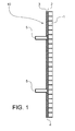
- the wear plate 10 includes a base plate 3, which acts as a substrate for the construction.
- the base plate 3 may be made of any suitable stiff material such as steel of various grades or various types of magnets, when magnetic force is utilized for attaching the wear plate.
- an abrasion-resistant element 1 Arranged parallel to the base plate 3 is an abrasion-resistant element 1, which has an integrated compression layer 2 for attachment to the base plate 3.
- the compression layer 2 is preferably made from an elastic material, such as rubber, or shock absorption material, the curing or vulcanizing temperature of which is preferably below 300 °C.
- the abrasion-resistant element 1 typically includes sacrificial material, which withstands highly abrasive circumstances.
- the sacrificial material may be for example, ceramic, metal, preferably steel, rubber or plastic or any combination thereof.
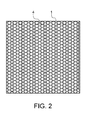
- the sacrificial material is embedded as cylindrical pieces into the receptive compression layer 2, which acts as frame for the abrasion-resistant element 1.
- a conductor 4 Arranged between the base plate 3 and the abrasion-resistant element 1 is a conductor 4 for carrying an electric signal.
- the electrical conductor 4 may be, for example, a steel wire, which is isolated by a glass fibre layer. It is advisable to isolate the conductors from each other for preventing false signals.
- the electrical conductor 4 is arranged to run within the wear plate 10 so as to cover the majority of the area of the wear plate 10.
- the terminals of the electrical conductor 4 are shown as black circles at the top right and bottom left corners of the wear plate 10.
- the pattern of the electrical conductor 4 is a so called zig zag pattern. Instead of an orthogonal zig zag pattern as shown in Fig. 2 , the electrical conductor 4 may generally speaking be arranged into an arbitrary pattern, such as an oval, twirl, circle or similar. Also, the ends of the electrical conductor 4, may alternatively terminate to the same conductor (not shown). Alternatively, the conductor pattern can be formed by a closed end pair cable, where the conductors are isolated from each other and connected to each other at one end. The end of the life span of the wear plate with this embodiment may be detected as a broken electric loop.
- the wear plate 10 may also be equipped with an integrated affixer 5 for attaching the wear plate 10 to a host bulk material handling device (not shown), such as a slide chute.
- the affixer 5 is attached to the base plate 3 and arranged to extend away from the abrasion-resistant element 1.
- the affixer 5 includes a threaded protrusion, i.e. a master tap, which terminates to a flange. The flange is fixed between the base plate 3 and abrasion-resistant element 1 such that the threaded protrusion extends through an opening in the base plate 3 and away from the abrasion-resistant element 1.
- a wear plate 10 as described above may be produced by as follows. Firstly, the sacrificial material is provided to a fixture to form the sacrificial portion of the abrasion-resistant element 1.
- the material may be ceramic, rubber, hardened steel or similar and it may be provided with a vast variety of different shapes, such as cylinders as depicted in the Figs. or one or several plate layers.
- the fixture holding the abrasion-resistant material may be a mould, jig or any suitable fixture capable of holding an array or an arbitrarily arranged plurality of abrasion-resistant material. Surface topography and chemistry of the wear resistant material may require pretreatment and/or specific adhesive material for the layer to achieve good surface wetting and bonding.
- a compression layer 2 is formed on the sacrificial material by providing rubber or a sheet of another shock absorption material on top of the sacrificial material.
- the compression layer 2 may be formed of a single layer or several layers of shock absorption material, wherein each layer may be of the same or different material.
- the electrical conductor 4 is installed.
- the electrical conductor 4 may be installed on the compression layer 2 or between several sub-layers of the shock absorption material forming the compression layer 2.
- the electrical conductor 4 is preferably superposed on the compression layer 2 as a pre-shaped element. Connection wires or cable of the conductor pattern is protruded through one or several holes (not shown) in the base plate 3 or on the side of the compression layer 2.
- the base plate 3 is superposed on the already established lamellar structure 1, 2, 4. If the wear plate 10 is made to include affixers 5, they are positioned on the compression layer 2 before providing the base plate 3. In most cases an adhesive material is used between the compression layer 2 and the base plate 3.
- the base plate 3 is preferably attached to the same fixture as the sacrificial material to prevent relative movement between the components of the wear plate 10.
- the entire wear plate 10 may be cured under pressure and relatively high temperature, such as up to pressure of 8 ... 10 bar and/or temperature of 150 ... 250 °C. Elevated pressure and temperature is particularly advisable, when rubber is used as an adhesive and as a compression layer material.
- the pressure and temperature depend on used materials and construction. Some technical materials can be cured in room temperature and under normal air pressure especially, when materials are used that require specific adhesive materials to achieve sufficient bonding force and low processing temperatures. TABLE 1: LIST OF REFERENCE NUMBERS. Number Part 1 abrasion-resistant element 2 compression layer 3 base plate 4 conductor 5 affixer 10 wear plate
Landscapes
- Engineering & Computer Science (AREA)
- Mechanical Engineering (AREA)
- Chutes (AREA)
Priority Applications (1)
| Application Number | Priority Date | Filing Date | Title |
|---|---|---|---|
| EP14171772.8A EP2955132A1 (de) | 2014-06-10 | 2014-06-10 | Verschleißplatte, Verfahren zu dessen Herstellung und Massenguthandhabungsvorrichtung |
Applications Claiming Priority (1)
| Application Number | Priority Date | Filing Date | Title |
|---|---|---|---|
| EP14171772.8A EP2955132A1 (de) | 2014-06-10 | 2014-06-10 | Verschleißplatte, Verfahren zu dessen Herstellung und Massenguthandhabungsvorrichtung |
Publications (1)
| Publication Number | Publication Date |
|---|---|
| EP2955132A1 true EP2955132A1 (de) | 2015-12-16 |
Family
ID=50980923
Family Applications (1)
| Application Number | Title | Priority Date | Filing Date |
|---|---|---|---|
| EP14171772.8A Withdrawn EP2955132A1 (de) | 2014-06-10 | 2014-06-10 | Verschleißplatte, Verfahren zu dessen Herstellung und Massenguthandhabungsvorrichtung |
Country Status (1)
| Country | Link |
|---|---|
| EP (1) | EP2955132A1 (de) |
Cited By (2)
| Publication number | Priority date | Publication date | Assignee | Title |
|---|---|---|---|---|
| WO2019018883A1 (en) * | 2017-07-26 | 2019-01-31 | International Materials & Technology Pty Limited | WEAR COVERS |
| EP4163238A1 (de) * | 2021-10-06 | 2023-04-12 | Maschinenfabrik Bernard Krone GmbH & Co. KG | Komponente für eine mobile arbeitsmaschine mit einer fördereinrichtung |
Citations (5)
| Publication number | Priority date | Publication date | Assignee | Title |
|---|---|---|---|---|
| GB2107288A (en) * | 1981-10-05 | 1983-04-27 | Steatite & Porcelain Prod Ltd | Impact-resistant wear plate |
| US5566626A (en) * | 1994-12-12 | 1996-10-22 | Rollins Environmental Services, Inc. | Incineration kiln devices and methods of protecting the same |
| US20050069016A1 (en) * | 2003-09-25 | 2005-03-31 | Kerr-Mcgee Chemical, Llc | Liner wear detection |
| AU2009101177A4 (en) * | 2009-11-17 | 2009-12-17 | Bradken Resources Pty Limited | Wear plate |
| CN201586533U (zh) | 2009-12-11 | 2010-09-22 | 成都利君实业股份有限公司 | 耐磨侧挡板 |
-
2014
- 2014-06-10 EP EP14171772.8A patent/EP2955132A1/de not_active Withdrawn
Patent Citations (5)
| Publication number | Priority date | Publication date | Assignee | Title |
|---|---|---|---|---|
| GB2107288A (en) * | 1981-10-05 | 1983-04-27 | Steatite & Porcelain Prod Ltd | Impact-resistant wear plate |
| US5566626A (en) * | 1994-12-12 | 1996-10-22 | Rollins Environmental Services, Inc. | Incineration kiln devices and methods of protecting the same |
| US20050069016A1 (en) * | 2003-09-25 | 2005-03-31 | Kerr-Mcgee Chemical, Llc | Liner wear detection |
| AU2009101177A4 (en) * | 2009-11-17 | 2009-12-17 | Bradken Resources Pty Limited | Wear plate |
| CN201586533U (zh) | 2009-12-11 | 2010-09-22 | 成都利君实业股份有限公司 | 耐磨侧挡板 |
Cited By (4)
| Publication number | Priority date | Publication date | Assignee | Title |
|---|---|---|---|---|
| WO2019018883A1 (en) * | 2017-07-26 | 2019-01-31 | International Materials & Technology Pty Limited | WEAR COVERS |
| US11261028B2 (en) | 2017-07-26 | 2022-03-01 | International Materials & Technology Pty Limited | Wear liners |
| AU2018308716B2 (en) * | 2017-07-26 | 2024-07-11 | International Materials & Technology Pty Limited | Wear liners |
| EP4163238A1 (de) * | 2021-10-06 | 2023-04-12 | Maschinenfabrik Bernard Krone GmbH & Co. KG | Komponente für eine mobile arbeitsmaschine mit einer fördereinrichtung |
Similar Documents
| Publication | Publication Date | Title |
|---|---|---|
| US11400604B2 (en) | Gripping device with monitoring of the operating state thereof | |
| EP3124420B1 (de) | Aufzugsanordnung mit einer elektrischen isolierung in einer stm-befestigungsanordnung und verfahren zur modernisierung einer bestehenden aufzugsanordnung | |
| US8861165B2 (en) | Strengthening element for a mounting flange of a hollow cylindrical insulator housing | |
| TWI372676B (en) | Methods and apparatus for polishing a semiconductor wafer | |
| EP2955132A1 (de) | Verschleißplatte, Verfahren zu dessen Herstellung und Massenguthandhabungsvorrichtung | |
| KR20190126437A (ko) | 누출 검지 시스템 | |
| KR20110084422A (ko) | 지지 벨트 | |
| CA2871971C (en) | Conveyor belt rip detection system with microwire sensor | |
| EA032168B1 (ru) | Устройство циклонного сепаратора и способ его производства | |
| AU2016245324A1 (en) | Conveyor pulley monitoring apparatus | |
| US20200410849A1 (en) | Precise predictive maintenance method for driving unit | |
| AU2014366879B2 (en) | Monitoring ore screening processes | |
| WO2010093668A1 (en) | Structural health monitoring system/method using electroactive polymer fibers | |
| CN101531311A (zh) | 电梯系统以及电梯系统的主曳引绳断线检测装置 | |
| US20180105391A1 (en) | Elevator system | |
| CN103283012A (zh) | 用于工艺盒的装载和卸载方法 | |
| EP3217028B1 (de) | Abgedichtetes gehäuse | |
| US7176421B2 (en) | Straight ribbon heater | |
| CN203364793U (zh) | 产品线束的长度检测装置 | |
| US7740235B2 (en) | Mount for equipment for conveying persons | |
| CN104696686A (zh) | 电力设备用金具及其加工方法 | |
| KR20150058426A (ko) | 엘리베이터 시스템을 위한 지지 수단 | |
| EP4483292A2 (de) | Herstellungsverfahren für hochfrequenzvorrichtungen | |
| CN102407998A (zh) | 搬运设备的皮带监控系统 | |
| CN210487123U (zh) | 一种防冲击的空压传感器 |
Legal Events
| Date | Code | Title | Description |
|---|---|---|---|
| PUAI | Public reference made under article 153(3) epc to a published international application that has entered the european phase |
Free format text: ORIGINAL CODE: 0009012 |
|
| AK | Designated contracting states |
Kind code of ref document: A1 Designated state(s): AL AT BE BG CH CY CZ DE DK EE ES FI FR GB GR HR HU IE IS IT LI LT LU LV MC MK MT NL NO PL PT RO RS SE SI SK SM TR |
|
| AX | Request for extension of the european patent |
Extension state: BA ME |
|
| STAA | Information on the status of an ep patent application or granted ep patent |
Free format text: STATUS: THE APPLICATION IS DEEMED TO BE WITHDRAWN |
|
| 18D | Application deemed to be withdrawn |
Effective date: 20160617 |