EP2955162A1 - Procédé et dispositif de fabrication d'un article en verre à partir de verre en fusion - Google Patents
Procédé et dispositif de fabrication d'un article en verre à partir de verre en fusion Download PDFInfo
- Publication number
- EP2955162A1 EP2955162A1 EP15169974.1A EP15169974A EP2955162A1 EP 2955162 A1 EP2955162 A1 EP 2955162A1 EP 15169974 A EP15169974 A EP 15169974A EP 2955162 A1 EP2955162 A1 EP 2955162A1
- Authority
- EP
- European Patent Office
- Prior art keywords
- glass
- mixing vessel
- molten glass
- stirring
- stirrer
- Prior art date
- Legal status (The legal status is an assumption and is not a legal conclusion. Google has not performed a legal analysis and makes no representation as to the accuracy of the status listed.)
- Granted
Links
- 239000000156 glass melt Substances 0.000 title claims abstract description 122
- 239000011521 glass Substances 0.000 title claims abstract description 81
- 238000000034 method Methods 0.000 title claims description 42
- 238000002156 mixing Methods 0.000 claims abstract description 157
- 239000006060 molten glass Substances 0.000 claims abstract description 141
- 238000003756 stirring Methods 0.000 claims abstract description 137
- 239000000203 mixture Substances 0.000 claims abstract description 31
- 230000015572 biosynthetic process Effects 0.000 claims abstract description 11
- 238000004519 manufacturing process Methods 0.000 claims abstract description 11
- 239000002344 surface layer Substances 0.000 claims abstract description 10
- 238000007493 shaping process Methods 0.000 claims description 8
- 238000007599 discharging Methods 0.000 claims description 6
- 238000005096 rolling process Methods 0.000 claims description 4
- 230000003287 optical effect Effects 0.000 description 10
- 230000008020 evaporation Effects 0.000 description 9
- 238000001704 evaporation Methods 0.000 description 9
- 240000005746 Ruta graveolens Species 0.000 description 8
- 229910003460 diamond Inorganic materials 0.000 description 8
- 239000010432 diamond Substances 0.000 description 8
- 230000000694 effects Effects 0.000 description 6
- 239000011435 rock Substances 0.000 description 6
- 238000000265 homogenisation Methods 0.000 description 5
- 239000011819 refractory material Substances 0.000 description 5
- 238000005498 polishing Methods 0.000 description 4
- 238000007667 floating Methods 0.000 description 3
- 239000010410 layer Substances 0.000 description 3
- 238000002844 melting Methods 0.000 description 3
- 230000008018 melting Effects 0.000 description 3
- 239000011241 protective layer Substances 0.000 description 3
- 239000000700 radioactive tracer Substances 0.000 description 3
- 239000004575 stone Substances 0.000 description 3
- 239000000758 substrate Substances 0.000 description 3
- 241001295925 Gegenes Species 0.000 description 2
- 239000000470 constituent Substances 0.000 description 2
- 239000005357 flat glass Substances 0.000 description 2
- 239000007789 gas Substances 0.000 description 2
- 238000010438 heat treatment Methods 0.000 description 2
- 238000000465 moulding Methods 0.000 description 2
- 239000010970 precious metal Substances 0.000 description 2
- 238000004381 surface treatment Methods 0.000 description 2
- 241001136792 Alle Species 0.000 description 1
- 238000006124 Pilkington process Methods 0.000 description 1
- QCWXUUIWCKQGHC-UHFFFAOYSA-N Zirconium Chemical compound [Zr] QCWXUUIWCKQGHC-UHFFFAOYSA-N 0.000 description 1
- 230000002411 adverse Effects 0.000 description 1
- 238000013019 agitation Methods 0.000 description 1
- 238000013459 approach Methods 0.000 description 1
- TZCXTZWJZNENPQ-UHFFFAOYSA-L barium sulfate Chemical compound [Ba+2].[O-]S([O-])(=O)=O TZCXTZWJZNENPQ-UHFFFAOYSA-L 0.000 description 1
- 239000000919 ceramic Substances 0.000 description 1
- 238000006243 chemical reaction Methods 0.000 description 1
- 239000000567 combustion gas Substances 0.000 description 1
- 230000007797 corrosion Effects 0.000 description 1
- 238000005260 corrosion Methods 0.000 description 1
- 230000006735 deficit Effects 0.000 description 1
- 230000006866 deterioration Effects 0.000 description 1
- 238000009792 diffusion process Methods 0.000 description 1
- 239000012535 impurity Substances 0.000 description 1
- 230000001737 promoting effect Effects 0.000 description 1
- 238000000926 separation method Methods 0.000 description 1
- 238000004088 simulation Methods 0.000 description 1
- XLYOFNOQVPJJNP-UHFFFAOYSA-N water Substances O XLYOFNOQVPJJNP-UHFFFAOYSA-N 0.000 description 1
- 229910052726 zirconium Inorganic materials 0.000 description 1
Images




Classifications
-
- C—CHEMISTRY; METALLURGY
- C03—GLASS; MINERAL OR SLAG WOOL
- C03B—MANUFACTURE, SHAPING, OR SUPPLEMENTARY PROCESSES
- C03B5/00—Melting in furnaces; Furnaces so far as specially adapted for glass manufacture
- C03B5/16—Special features of the melting process; Auxiliary means specially adapted for glass-melting furnaces
- C03B5/18—Stirring devices; Homogenisation
- C03B5/187—Stirring devices; Homogenisation with moving elements
-
- B—PERFORMING OPERATIONS; TRANSPORTING
- B01—PHYSICAL OR CHEMICAL PROCESSES OR APPARATUS IN GENERAL
- B01F—MIXING, e.g. DISSOLVING, EMULSIFYING OR DISPERSING
- B01F27/00—Mixers with rotary stirring devices in fixed receptacles; Kneaders
- B01F27/05—Stirrers
- B01F27/07—Stirrers characterised by their mounting on the shaft
- B01F27/072—Stirrers characterised by their mounting on the shaft characterised by the disposition of the stirrers with respect to the rotating axis
- B01F27/0722—Stirrers characterised by their mounting on the shaft characterised by the disposition of the stirrers with respect to the rotating axis perpendicular with respect to the rotating axis
-
- B—PERFORMING OPERATIONS; TRANSPORTING
- B01—PHYSICAL OR CHEMICAL PROCESSES OR APPARATUS IN GENERAL
- B01F—MIXING, e.g. DISSOLVING, EMULSIFYING OR DISPERSING
- B01F27/00—Mixers with rotary stirring devices in fixed receptacles; Kneaders
- B01F27/05—Stirrers
- B01F27/11—Stirrers characterised by the configuration of the stirrers
- B01F27/112—Stirrers characterised by the configuration of the stirrers with arms, paddles, vanes or blades
-
- B—PERFORMING OPERATIONS; TRANSPORTING
- B01—PHYSICAL OR CHEMICAL PROCESSES OR APPARATUS IN GENERAL
- B01F—MIXING, e.g. DISSOLVING, EMULSIFYING OR DISPERSING
- B01F27/00—Mixers with rotary stirring devices in fixed receptacles; Kneaders
- B01F27/05—Stirrers
- B01F27/11—Stirrers characterised by the configuration of the stirrers
- B01F27/19—Stirrers with two or more mixing elements mounted in sequence on the same axis
- B01F27/192—Stirrers with two or more mixing elements mounted in sequence on the same axis with dissimilar elements
-
- B—PERFORMING OPERATIONS; TRANSPORTING
- B01—PHYSICAL OR CHEMICAL PROCESSES OR APPARATUS IN GENERAL
- B01F—MIXING, e.g. DISSOLVING, EMULSIFYING OR DISPERSING
- B01F27/00—Mixers with rotary stirring devices in fixed receptacles; Kneaders
- B01F27/50—Pipe mixers, i.e. mixers wherein the materials to be mixed flow continuously through pipes, e.g. column mixers
-
- B—PERFORMING OPERATIONS; TRANSPORTING
- B01—PHYSICAL OR CHEMICAL PROCESSES OR APPARATUS IN GENERAL
- B01F—MIXING, e.g. DISSOLVING, EMULSIFYING OR DISPERSING
- B01F33/00—Other mixers; Mixing plants; Combinations of mixers
- B01F33/80—Mixing plants; Combinations of mixers
- B01F33/81—Combinations of similar mixers, e.g. with rotary stirring devices in two or more receptacles
- B01F33/811—Combinations of similar mixers, e.g. with rotary stirring devices in two or more receptacles in two or more consecutive, i.e. successive, mixing receptacles or being consecutively arranged
-
- B—PERFORMING OPERATIONS; TRANSPORTING
- B01—PHYSICAL OR CHEMICAL PROCESSES OR APPARATUS IN GENERAL
- B01F—MIXING, e.g. DISSOLVING, EMULSIFYING OR DISPERSING
- B01F35/00—Accessories for mixers; Auxiliary operations or auxiliary devices; Parts or details of general application
- B01F35/50—Mixing receptacles
- B01F35/53—Mixing receptacles characterised by the configuration of the interior, e.g. baffles for facilitating the mixing of components
-
- C—CHEMISTRY; METALLURGY
- C03—GLASS; MINERAL OR SLAG WOOL
- C03B—MANUFACTURE, SHAPING, OR SUPPLEMENTARY PROCESSES
- C03B5/00—Melting in furnaces; Furnaces so far as specially adapted for glass manufacture
- C03B5/16—Special features of the melting process; Auxiliary means specially adapted for glass-melting furnaces
- C03B5/20—Bridges, shoes, throats, or other devices for withholding dirt, foam, or batch
-
- Y—GENERAL TAGGING OF NEW TECHNOLOGICAL DEVELOPMENTS; GENERAL TAGGING OF CROSS-SECTIONAL TECHNOLOGIES SPANNING OVER SEVERAL SECTIONS OF THE IPC; TECHNICAL SUBJECTS COVERED BY FORMER USPC CROSS-REFERENCE ART COLLECTIONS [XRACs] AND DIGESTS
- Y02—TECHNOLOGIES OR APPLICATIONS FOR MITIGATION OR ADAPTATION AGAINST CLIMATE CHANGE
- Y02P—CLIMATE CHANGE MITIGATION TECHNOLOGIES IN THE PRODUCTION OR PROCESSING OF GOODS
- Y02P40/00—Technologies relating to the processing of minerals
- Y02P40/50—Glass production, e.g. reusing waste heat during processing or shaping
- Y02P40/57—Improving the yield, e-g- reduction of reject rates
Definitions
- the invention relates to a method for producing a glass article from a molten glass.
- the invention relates to an apparatus for producing a glass article from a molten glass.
- Such methods and devices are basically, eg from the writings DE 10 2006 060 972 A1 .
- the devices used for the production of glass comprising a stirring device with arranged in the stirrer paddle, are used to improve the large-scale volume homogeneity and small-space homogeneity (Schlierenson) of the glass melt.
- they have a much longer residence time of the glass melt in the stirring device compared to small-sized stirring devices (with smaller free surfaces). The free surface is exposed to the atmosphere for a longer time, which can lead to evaporation and other chemical reactions and thereby to a deterioration of the homogeneity of the glass melt and ultimately of the resulting display glass.
- the surface of the glass melt in the mixing vessel generally also increases.
- this can lead to an undesirable change in the composition of the molten glass at the surface in the mixing vessel.
- Lighter volatile composition components of the molten glass such as Li, Na, K, B, P, F, Cl, accumulate.
- combustion gases in particular H 2 O can be registered in the molten glass and accumulate.
- the object of the invention is to find an improved method and an improved apparatus for the economical production of a glass article from a molten glass.
- the uppermost stirring blade is configured in such a way and arranged at a distance A1 from the surface of the glass melt in the mixing vessel that this essentially causes it to be pulled in.
- a protective layer (with a composition other than the composition of the molten glass introduced) can form on the surface of the molten glass in the mixing vessel. which effectively prevents a further change in the composition of the molten glass in the mixing vessel, so that no disturbing inhomogeneities can form below the protective layer.
- Glass articles such as by stirring the glass melt, which is located on the surface in the mixing vessel, not (very high demands on the optical properties of the glass article) or only slightly (at least so that the glass article to be produced in particular meets the optical specifications) in the Stirred vessel is retracted.
- the uppermost stirring blade is preferably configured in such a way and arranged at a distance A2 from the surface of the glass melt in the mixing vessel that substantially or not the glass melt which is located on the surface in the mixing vessel is drawn into the mixing vessel.
- the paddle stirrer has a plurality of stirring vanes, wherein the topmost stirring blade generates a downward flow of the glass melt along the agitator shaft and the bottommost stirring blade generates an upward flow of the glass melt along the agitator shaft.
- the paddle stirrer has a plurality of stirring vanes, wherein a smaller distance is set between adjacent stirring vanes, which produce a rectified flow of the glass melt along the agitator shaft, than between adjacent stirring vanes, which produce an opposite flow of the glass melt along the agitator shaft.
- the continuous introduction of the glass melt can take place in an upper region of the mixing vessel and the continuous discharge in a lower region of the mixing vessel or vice versa.
- the viscosity of the glass melt is between 100 and 300 Pas.
- stirred vessels can be arranged in series.
- the glass melt located on the surface in the agitating vessel can have a maximum amplitude of up and down movement of the glass melt at the surface of at most 2%, preferably at most 1% of the glass melting height in the agitating vessel at a stirrer speed of 6 U / effect min.
- the stirrer speed can be set in the range of 0.5 to 20 rpm, preferably 1 to 15 rpm, and particularly preferably 2 to 10 rpm.
- the molding of the molten glass may include floating, drawing or rolling the molten glass.
- the object of the invention is achieved by one of the two devices (device 1 and device 2) with the following features (method 1 is carried out by means of device 1, method 2 by means of device 2):
- the uppermost stirring blade is preferably configured in such a way and arranged at a distance A1 from the surface of the glass melt in the mixing vessel that this essentially causes it to be pulled in.
- the uppermost impeller is preferably configured in such a way and arranged at a distance A2 from the surface of the molten glass in the mixing vessel that substantially or completely the molten glass which is located on the surface in the mixing vessel is not or only insignificantly drawn into the mixing vessel.
- the respective stirring blades consist of two sub-wings, which have a common colinear symmetry axis which passes perpendicular to the agitator shaft.
- the mixing blade which consists of two sub-blades, has a defined blade diameter and describes a stirring diameter in the mixing vessel.
- the two parts of the impeller have a geometry that support the conveying effect, for example a diamond geometry, wherein the preferred ratio of the length of the diagonal is 1: 1 to 1: 2.
- the inventors have recognized that according to measure a) the molten glass, which is located on the surface of the mixing vessel is continuously mixed with the rest of the molten glass in the mixing vessel and thus the inhomogeneities forming on the surface of the molten glass are continuously dissolved and mixed as best as possible before whose expression becomes too large to adversely affect the quality of the resulting glass article.
- the inventors have recognized that according to measure b) the molten glass, which is located on the surface of the mixing vessel, as possible in Rest is left, so that the inhomogeneities forming on the surface are mixed as little as possible with the rest of the molten glass and thus can affect the quality of the resulting glass article less negative.
- the molten glass which is located on the surface in the mixing vessel, preferably a maximum amplitude of the up and down movement of the glass melt on the surface (slosh) of at most 20 mm, preferably of at most 10 mm and more preferably of at most 5 mm up.
- a maximum amplitude of the up and down movement of the glass melt on the surface (slosh) of at most 20 mm, preferably of at most 10 mm and more preferably of at most 5 mm up.
- a wall shear stress of less than 500 Pa, in particular of less than 400 Pa is set in the mixing vessel.
- the throughput time can be determined for example by means of a tracer test, wherein a tracer is added to the molten glass during introduction of the glass melt into the mixing vessel, at the same time another tracer is placed on the surface of the molten glass in the mixing vessel and the flow time of both tracers at one point the discharge is determined.
- a flat glass for example a display glass or a covering glass for electronic devices such as smartphones, tablet computers or monitors with a maximum amplitude of the strip-shaped height fluctuations of the glass surface
- waviness RMS value of the surface profile for pattern widths between 0.8 mm and 8 mm; SEMI D24-2000; Specification for glass substrates used to manufacture flat panel displays 2006
- the stirring concept has been modified in such a way that it prevents chemically modified surface glass melt with a high viscosity from entering the already stirred or homogenized glass melt and causing drawing stripes or waviness problems.
- the smallest composition or viscosity inhomogeneities on the surface form uncontrollably in the glass article and cause unevenness, drawing strips, Waviness problems or other surface effects that make subsequent and expensive surface treatment or polishing of the glass article necessary. It is therefore no longer sufficient to make only the glass melt volume streak-free, but the molten glass on the surface in the mixing vessel must be taken into account specifically in the homogenization process.
- volume homogenization can be significantly improved by larger stirred vessels, but larger agitating vessels also increases the free surface of the glass melt in the mixing vessel and thus also the susceptibility to surface-induced drawing strips or Wavinessprobleme in the resulting glass article.
- inventive method and the devices according to the invention are suitable to meet very high demands on the glass quality with respect. Homogeneity and Schlierenford, and beyond able to continuously stir the molten glass at the Retzgefäßober Structure according to method 1 / device 1 or feature a), so that the glass melt surface is permanently replaced and the formation of a chemically modified glass melt surface is suppressed.
- the method and apparatus are designed in such a way that the glass surface in the mixing vessel is substantially not touched during stirring, except for, for example, the stirrer shaft of the paddle stirrer, so that a stable "skin" forms on the glass surface, which further volatilizes evaporation Glass components prevented (method 2 / device 2 or feature b)).
- the device may preferably have a typical stirrer speed of 6 rpm.
- the geometry of the stirring vessel is preferably approximately a square cylinder (D approximately L).
- the means for stirring the molten glass are designed and arranged such that the molten glass (12), which is located on the surface in the mixing vessel (1) can be drawn into the mixing vessel (1), so that the formation of a surface layer of the molten glass with a composition other than the composition of the introduced molten glass (11) can be prevented or at least minimized.
- the uppermost stirring blade (9) is designed in such a way and arranged at a distance A1 from the surface (13) of the molten glass (11) in the mixing vessel (1), so that essentially retraction is effected.
- the molten glass (11) is introduced continuously into a mixing vessel (1) through an inlet (2).
- the stirring of the glass melt (11) in the mixing vessel (1) takes place by means of a paddle stirrer, wherein the paddle stirrer has five stirring vanes (5, 6, 7, 8, 9) which are arranged on a stirrer shaft (3) arranged substantially vertically in the stirring vessel (1). 4) are attached.
- the molten glass (11) is continuously discharged from the mixing vessel (1) through the outlet (3).
- the molding of the molten glass (11) to obtain the glass article takes place in a subsequent process step, e.g. Floating the glass melt or rolling or pulling the molten glass (11).
- the molten glass (12) which is located on the surface in the mixing vessel (1), drawn into the mixing vessel (top, dashed arrows), so that the formation of a surface layer of the molten glass with a composition other than the composition of the introduced Glass melt (11) is prevented or at least minimized.
- the uppermost stirring blade (9) is configured in such a way and arranged at a distance A1 from the surface (13) of the molten glass (11) in the mixing vessel (1), that substantially retraction is effected.
- the molten glass (12) which is located on the surface in the mixing vessel (1), is drawn into the mixing vessel (1), in particular to the agitator shaft (4), even minimal changes in the composition of the molten glass (12) at its Surface balanced. The, if only slightly changed surface glass melt (12) is mixed in good time with the rest of the molten glass (11), so that no disturbing inhomogeneities can form.
- the blade stirrer has, as mentioned, a plurality of impellers (5, 6, 7, 8, 9), wherein the uppermost impeller (9) and the following impellers (7, 8) a downward flow of the molten glass along the agitator shaft (4) and the lowermost impeller (5) and the stirring blade (6) arranged above produce an upward flow of the molten glass along the agitator shaft (4).
- the conveying direction (17) of the stirring blades (5, 6, 7, 8, 9) is represented by arrows on the stirring blade ends.
- the larger distance (15) between the impellers (6,7) is also shown.
- the impellers have a diamond geometry (see Fig. 1 b) Depending on the arrangement of the rhombus, the corresponding downward or upward promotion is supported.
- the continuous introduction of the molten glass (11) takes place in an upper region of the mixing vessel (1) and the continuous discharge in a lower region of the mixing vessel (1).
- FIG. 2 shows a device 1 according to the invention wherein the inlet (2) in the lower region of the mixing vessel (1) and the outlet (3) is in the upper region of the mixing vessel (1).
- a so-called hanging rock (18) is arranged to ensure a symmetrical and uniform retraction of the surface.
- FIGS. 3a to 3d show the device 1 according to the invention FIG. 2 from above (without representation of the impellers).
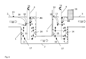
- FIG. 4 shows two devices 1 according to the invention, wherein two mixing vessels (1) are arranged in series.
- the homogenizing effect is significantly improved according to the equation for the homogeneity number H.
- the means for stirring the glass melt (11) are in this case configured and arranged such that the glass melt (12), which is located on the surface in the mixing vessel (1), can not or only slightly be drawn into the mixing vessel (1).
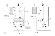
- the uppermost stirring blade (8) is configured in such a way and arranged at a distance A2 from the surface (13) of the molten glass (11) in the mixing vessel (1) that essentially the molten glass (12) which forms on the surface in the mixing vessel (12). 1), is not or only slightly fed into the mixing vessel (1).
- the molten glass (11) is introduced continuously into a mixing vessel (1) through an inlet (2).
- the stirring of the glass melt (11) in the mixing vessel (1) takes place by means of a paddle stirrer, wherein the paddle stirrer has four stirring vanes (5, 6, 7, 8) which are arranged on a stirrer shaft (4) arranged essentially vertically in the stirring vessel (1). are attached.
- the molten glass (11) is continuously passed from the mixing vessel (1) through the outlet (3).
- the glass melt (11) is molded to obtain the glass article in a subsequent process step, for example by floating the glass melt (11) or by rolling or drawing the glass melt (11).
- the molten glass (11) which is located on the surface (12) in the mixing vessel (1), not or only slightly absorbed into the mixing vessel.
- the glass melt (12), which is located on the surface in the mixing vessel (1) is not or only slightly fed into the mixing vessel (1), a protective layer with a different composition than the composition of the introduced glass melt (11 ) on the surface of the molten glass in the mixing vessel (1), which effectively prevents a further change in the composition of the molten glass (11) in the mixing vessel (1), so that no disturbing inhomogeneities can form.
- the glass article to be produced such as by stirring the glass melt (12), which is located on the surface in the mixing vessel (1), not (very high demands on the optical properties of the glass article) or only slightly (at least in that the glass article to be produced in particular satisfies the optical specifications) is drawn into the mixing vessel (1).
- the uppermost stirring blade (8) is designed and arranged at a distance A2 (A2> A1) from the surface (13) of the molten glass in the mixing vessel such that essentially the molten glass (12) which forms on the surface in the mixing vessel (1 ), is not or only slightly fed into the mixing vessel (1).
- the paddle stirrer has, as mentioned, a plurality of stirring vanes (5, 6, 7, 8), wherein the uppermost stirring blade (8) and the subsequent underlying stirring blade (7) have a downward flow of the molten glass (11) along the agitator shaft (4) and the lowest Agitator (5) and the above arranged stirring blades (6) produce an upward flow of the glass melt (11) along the agitator shaft (5).
- a smaller distance is set than between adjacent impellers (6, 7), the one generate oppositely directed flow of molten glass along the agitator shaft (4).
- the continuous introduction of the glass melt (11) takes place here in the upper region of the mixing vessel (1) and the continuous discharge in the lower region of the mixing vessel (1).
- stirred vessels (1) can be arranged in series.
- a so-called hanging rock (18) is arranged to already impurities, inhomogeneities, which are located on the surface of the glass melt to be introduced (11) are kept away from the mixing vessel (1).
- Method 2 and device 2 are also possible without hanging stone, depending on the homogeneity requirements, high homogeneity requires a hanging rock in the inlet and / or outlet.
- the molten glass (12) located at the surface in the agitating vessel can only have a maximum amplitude of up and down movement of the molten glass at the surface of at most 2%, preferably at most 1% of the glass melting height in the agitating vessel at a stirrer speed of 6 rpm.
- the impellers have a diamond geometry (see Fig. 5c and 5d ), depending on the arrangement of the rhombus thus the corresponding downward or upward promotion is supported.
- FIG. 6 shows a device 2 according to the invention, wherein the inlet (2) in the lower region of the mixing vessel (1) and the outlet (3) in the upper region of the mixing vessel (1) is arranged.
Landscapes
- Chemical & Material Sciences (AREA)
- Chemical Kinetics & Catalysis (AREA)
- Engineering & Computer Science (AREA)
- Materials Engineering (AREA)
- Organic Chemistry (AREA)
- Glass Compositions (AREA)
- Mixers Of The Rotary Stirring Type (AREA)
Applications Claiming Priority (1)
| Application Number | Priority Date | Filing Date | Title |
|---|---|---|---|
| DE102014211346.6A DE102014211346A1 (de) | 2014-06-13 | 2014-06-13 | Verfahren und Vorrichtung zur Herstellung eines Glasartikels aus einer Glasschmelze |
Publications (2)
| Publication Number | Publication Date |
|---|---|
| EP2955162A1 true EP2955162A1 (fr) | 2015-12-16 |
| EP2955162B1 EP2955162B1 (fr) | 2019-07-03 |
Family
ID=53396226
Family Applications (1)
| Application Number | Title | Priority Date | Filing Date |
|---|---|---|---|
| EP15169974.1A Active EP2955162B1 (fr) | 2014-06-13 | 2015-05-29 | Procédé de fabrication d'un article en verre à partir de verre en fusion |
Country Status (6)
| Country | Link |
|---|---|
| US (1) | US20150360990A1 (fr) |
| EP (1) | EP2955162B1 (fr) |
| JP (1) | JP6590540B2 (fr) |
| KR (1) | KR20150143324A (fr) |
| CN (1) | CN105314819A (fr) |
| DE (1) | DE102014211346A1 (fr) |
Cited By (3)
| Publication number | Priority date | Publication date | Assignee | Title |
|---|---|---|---|---|
| USD849070S1 (en) * | 2015-02-23 | 2019-05-21 | Umicore Ag & Co. Kg | Stirrer |
| DE102020103328A1 (de) | 2020-02-10 | 2021-08-12 | Schott Ag | Verfahren und Vorrichtung zum Homogenisieren von viskosen Flüssigkeiten |
| CN119140003A (zh) * | 2024-11-15 | 2024-12-17 | 昌邑森汇新材料有限公司 | 一种用于生产可膨胀石墨的设备、控制系统及控制方法 |
Families Citing this family (3)
| Publication number | Priority date | Publication date | Assignee | Title |
|---|---|---|---|---|
| KR102415723B1 (ko) * | 2017-11-20 | 2022-07-04 | 코닝 인코포레이티드 | 용탕 교반 시스템 및 용탕 교반 방법 |
| CN108971442B (zh) * | 2018-07-27 | 2020-10-27 | 青海盐湖工业股份有限公司 | 一种用于对金属镁熔体进行强剪切的装置 |
| CN116621426B (zh) * | 2023-05-26 | 2026-02-03 | 湖南旗滨医药材料科技有限公司 | 玻璃液供料均化装置及其控制方法、玻璃制品生产系统 |
Citations (7)
| Publication number | Priority date | Publication date | Assignee | Title |
|---|---|---|---|---|
| US2871000A (en) * | 1956-03-12 | 1959-01-27 | American Optical Corp | Apparatus for stirring glass |
| DE19960212A1 (de) * | 1999-12-14 | 2001-07-12 | Schott Rohrglas Gmbh | Rührvorrichtung zur Homogenisierung einer Glasschmelze in Rührtiegeln |
| DE102006060972A1 (de) | 2006-12-20 | 2008-06-26 | Schott Ag | Verfahren und Vorrichtung zum Homogenisieren einer Glasschmelze |
| DE102007035203A1 (de) | 2007-07-25 | 2009-01-29 | Schott Ag | Verfahren und Vorrichtung zum Homogenisieren einer Glasschmelze |
| WO2011106605A2 (fr) * | 2010-02-25 | 2011-09-01 | Corning Incorporated | Équipement pour fabriquer un article en verre et procédés |
| EP2505562A1 (fr) * | 2010-11-01 | 2012-10-03 | Avanstrate Inc. | Procédé pour fabriquer un substrat en verre et dispositif d'agitation |
| US20130125591A1 (en) * | 2011-11-18 | 2013-05-23 | Avanstrate Inc. | Method of manufacturing glass, and stirring device |
Family Cites Families (23)
| Publication number | Priority date | Publication date | Assignee | Title |
|---|---|---|---|---|
| US2569549A (en) * | 1949-03-21 | 1951-10-02 | Du Pont | Imidohalides and process of preparing them and their hydrolysis products |
| US2831664A (en) * | 1953-10-30 | 1958-04-22 | Corning Glass Works | Glass stirring |
| US2891777A (en) * | 1955-03-08 | 1959-06-23 | Pittsburgh Plate Glass Co | Glass stirring mechanism |
| US3419373A (en) * | 1967-10-25 | 1968-12-31 | Owens Illinois Inc | Pumping vane type glass feeder |
| US3539117A (en) * | 1968-04-11 | 1970-11-10 | Sweco Inc | Material treatment apparatus with rotary stirrer in vibratory container |
| JPS596254B2 (ja) * | 1976-09-14 | 1984-02-09 | 旭硝子株式会社 | 堅型電気熔融炉におけるガラスの均質化方法 |
| JPS5524111Y2 (fr) * | 1978-02-09 | 1980-06-09 | ||
| JPS5888126A (ja) * | 1981-11-16 | 1983-05-26 | Nippon Sheet Glass Co Ltd | 溶融ガラスの撹拌装置 |
| JPH04160018A (ja) * | 1990-10-23 | 1992-06-03 | Nippon Sheet Glass Co Ltd | ガラス連続成形用撹拌装置 |
| JP3116400B2 (ja) * | 1991-03-18 | 2000-12-11 | 日本板硝子株式会社 | ガラス素地均質化方法 |
| CN1163602A (zh) * | 1994-11-15 | 1997-10-29 | 伊尔默瑙玻璃技术有限公司 | 玻璃熔液均质化的方法和设备 |
| JPH10265227A (ja) * | 1997-03-21 | 1998-10-06 | Nippon Electric Glass Co Ltd | 溶融ガラス攪拌体 |
| KR100878605B1 (ko) * | 2001-11-30 | 2009-01-15 | 코닝 인코포레이티드 | 교반에 의한 용융 유리 균질화 방법 및 장치 |
| US20060042318A1 (en) * | 2004-08-31 | 2006-03-02 | Burdette Steven R | Method and apparatus for homogenizing a glass melt |
| DE102008017045B9 (de) * | 2008-04-03 | 2012-07-05 | Umicore Ag & Co. Kg | Rührsystem und Verfahren zum Homogenisieren von Glasschmelzen |
| DE102008047123A1 (de) * | 2008-07-31 | 2010-02-04 | Walter Lindner | Feeder oder Rührzelle für die Glasindustrie |
| US8087262B2 (en) * | 2008-11-18 | 2012-01-03 | Corning Incorporated | Platinum condensation abatement by electrostatic precipitation |
| EP3354626A1 (fr) * | 2009-08-21 | 2018-08-01 | Umicore Ag & Co. Kg | Appareil de mélange |
| US8978419B2 (en) * | 2009-11-30 | 2015-03-17 | Corning Incorporated | Devices for controlling atmosphere over molten-glass free-surfaces |
| US8240170B2 (en) * | 2010-02-22 | 2012-08-14 | Corning Incorporated | Apparatus for sealing a joint between vessels for conveying molten glass |
| DE102010000546B4 (de) * | 2010-02-25 | 2013-04-25 | Schott Ag | Vorrichtung zum Homogenisieren einer Glasschmelze, Rührvorrichtung und Verwendung |
| US8650910B2 (en) * | 2010-08-23 | 2014-02-18 | Corning Incorporated | Apparatus for homogenizing a glass melt |
| JP2013249247A (ja) * | 2012-05-01 | 2013-12-12 | Avanstrate Inc | ガラス基板の製造方法、ガラス基板の製造装置および攪拌装置 |
-
2014
- 2014-06-13 DE DE102014211346.6A patent/DE102014211346A1/de not_active Ceased
-
2015
- 2015-05-29 EP EP15169974.1A patent/EP2955162B1/fr active Active
- 2015-06-09 KR KR1020150081144A patent/KR20150143324A/ko not_active Withdrawn
- 2015-06-10 JP JP2015117439A patent/JP6590540B2/ja active Active
- 2015-06-12 CN CN201510325049.9A patent/CN105314819A/zh active Pending
- 2015-06-15 US US14/739,780 patent/US20150360990A1/en not_active Abandoned
Patent Citations (7)
| Publication number | Priority date | Publication date | Assignee | Title |
|---|---|---|---|---|
| US2871000A (en) * | 1956-03-12 | 1959-01-27 | American Optical Corp | Apparatus for stirring glass |
| DE19960212A1 (de) * | 1999-12-14 | 2001-07-12 | Schott Rohrglas Gmbh | Rührvorrichtung zur Homogenisierung einer Glasschmelze in Rührtiegeln |
| DE102006060972A1 (de) | 2006-12-20 | 2008-06-26 | Schott Ag | Verfahren und Vorrichtung zum Homogenisieren einer Glasschmelze |
| DE102007035203A1 (de) | 2007-07-25 | 2009-01-29 | Schott Ag | Verfahren und Vorrichtung zum Homogenisieren einer Glasschmelze |
| WO2011106605A2 (fr) * | 2010-02-25 | 2011-09-01 | Corning Incorporated | Équipement pour fabriquer un article en verre et procédés |
| EP2505562A1 (fr) * | 2010-11-01 | 2012-10-03 | Avanstrate Inc. | Procédé pour fabriquer un substrat en verre et dispositif d'agitation |
| US20130125591A1 (en) * | 2011-11-18 | 2013-05-23 | Avanstrate Inc. | Method of manufacturing glass, and stirring device |
Cited By (5)
| Publication number | Priority date | Publication date | Assignee | Title |
|---|---|---|---|---|
| USD849070S1 (en) * | 2015-02-23 | 2019-05-21 | Umicore Ag & Co. Kg | Stirrer |
| US10676385B2 (en) | 2015-02-23 | 2020-06-09 | Umicore Ag & Co. Kg | Device for stirring molten gas |
| USD918279S1 (en) | 2015-02-23 | 2021-05-04 | Umicore Ag & Co. Kg | Stirrer |
| DE102020103328A1 (de) | 2020-02-10 | 2021-08-12 | Schott Ag | Verfahren und Vorrichtung zum Homogenisieren von viskosen Flüssigkeiten |
| CN119140003A (zh) * | 2024-11-15 | 2024-12-17 | 昌邑森汇新材料有限公司 | 一种用于生产可膨胀石墨的设备、控制系统及控制方法 |
Also Published As
| Publication number | Publication date |
|---|---|
| DE102014211346A1 (de) | 2015-12-17 |
| JP2016006006A (ja) | 2016-01-14 |
| KR20150143324A (ko) | 2015-12-23 |
| CN105314819A (zh) | 2016-02-10 |
| US20150360990A1 (en) | 2015-12-17 |
| JP6590540B2 (ja) | 2019-10-16 |
| EP2955162B1 (fr) | 2019-07-03 |
Similar Documents
| Publication | Publication Date | Title |
|---|---|---|
| EP2955162B1 (fr) | Procédé de fabrication d'un article en verre à partir de verre en fusion | |
| EP2361890B1 (fr) | Dispositif d'homogénéisation d'un bain de verre et son utilisation | |
| DE102007035203B4 (de) | Verfahren und Vorrichtung zum Homogenisieren einer Glasschmelze, sowie Verwendung | |
| DE2603561C2 (de) | Glasschmelzbehälter | |
| AT15242U1 (de) | Vorrichtung zum Rühren von geschmolzenem Glas, Einrichtung zum Rühren von geschmolzenem Glas umfassend eine solche Vorrichtung und die Verwendung einer solchen Vorrichtung | |
| DE102008017045A1 (de) | Rührbehälter, Rührsystem und Verfahren zum Homogenisieren von Glasschmelzen | |
| DE102006060972B4 (de) | Verfahren und Vorrichtung zum Homogenisieren einer Glasschmelze, sowie Verwendung | |
| DE102018122017A1 (de) | Schmelzraum eines kontinuierlichen Glasschmelzofens und Verfahren zum Glasschmelzen in diesem Schmelzraum | |
| DE102019120065A1 (de) | Vorrichtung und Verfahren zur Herstellung von Glasbändern | |
| EP3770125B1 (fr) | Dispositif et procédé de fabrication de rubans de verre | |
| DE1457065A1 (de) | Verfahren und Vorrichtung zum Ruehren von und zur Erzeugung einer Zirkulation in Fluessigkeitsmengen | |
| DE102005050871B4 (de) | Verfahren und Vorrichtung zum Konditionieren und Homogenisieren von Glasschmelzen | |
| DE20321483U1 (de) | Aus PGM-Werkstoffen gefertigte Läuterkammer | |
| DE102013203624A1 (de) | Vorrichtung und Verfahren zum Abziehen einer Oberflächenglasschicht und Glaswanne oder -rinne mit einer solchen Vorrichtung | |
| DE69601339T2 (de) | Verfahren und Vorrichtung zum Homogenisieren von geschmolzenem Glas durch Rühren | |
| DE1496443A1 (de) | Vorrichtung zum Verruehren von Glas | |
| DE2743289C3 (de) | Vorrichtung zum Mischen und Homogenisieren von geschmolzenem Glas in einem Vorherd | |
| DE102020103328A1 (de) | Verfahren und Vorrichtung zum Homogenisieren von viskosen Flüssigkeiten | |
| DE10200233C1 (de) | Vorrichtung zum Läutern einer Glasschmelze mit einer Unterdruck-Läuterkammer | |
| DE102005013468B4 (de) | Vorrichtung und Verfahren zum Läutern von Glas | |
| DE102013006816B4 (de) | Veränderung der Anordnung von Rührstäben bei Rührwerken und Mixern | |
| EP4306489B1 (fr) | Cuve de fusion de verre pour fonctionnement tout électrique | |
| DE2508471B2 (de) | Vorrichtung und Verfahren zur Herstellung von Flachglas | |
| DE102004013725B4 (de) | Verfahren und System zur Förderung und/oder Homogenisierung einer anorganischen Schmelze | |
| DE1926987A1 (de) | Polykondensationsvorrichtung |
Legal Events
| Date | Code | Title | Description |
|---|---|---|---|
| PUAI | Public reference made under article 153(3) epc to a published international application that has entered the european phase |
Free format text: ORIGINAL CODE: 0009012 |
|
| 17P | Request for examination filed |
Effective date: 20150619 |
|
| AK | Designated contracting states |
Kind code of ref document: A1 Designated state(s): AL AT BE BG CH CY CZ DE DK EE ES FI FR GB GR HR HU IE IS IT LI LT LU LV MC MK MT NL NO PL PT RO RS SE SI SK SM TR |
|
| AX | Request for extension of the european patent |
Extension state: BA ME |
|
| STAA | Information on the status of an ep patent application or granted ep patent |
Free format text: STATUS: EXAMINATION IS IN PROGRESS |
|
| 17Q | First examination report despatched |
Effective date: 20161215 |
|
| GRAP | Despatch of communication of intention to grant a patent |
Free format text: ORIGINAL CODE: EPIDOSNIGR1 |
|
| STAA | Information on the status of an ep patent application or granted ep patent |
Free format text: STATUS: GRANT OF PATENT IS INTENDED |
|
| INTG | Intention to grant announced |
Effective date: 20190306 |
|
| GRAS | Grant fee paid |
Free format text: ORIGINAL CODE: EPIDOSNIGR3 |
|
| GRAA | (expected) grant |
Free format text: ORIGINAL CODE: 0009210 |
|
| STAA | Information on the status of an ep patent application or granted ep patent |
Free format text: STATUS: THE PATENT HAS BEEN GRANTED |
|
| AK | Designated contracting states |
Kind code of ref document: B1 Designated state(s): AL AT BE BG CH CY CZ DE DK EE ES FI FR GB GR HR HU IE IS IT LI LT LU LV MC MK MT NL NO PL PT RO RS SE SI SK SM TR |
|
| REG | Reference to a national code |
Ref country code: GB Ref legal event code: FG4D Free format text: NOT ENGLISH |
|
| REG | Reference to a national code |
Ref country code: CH Ref legal event code: EP Ref country code: AT Ref legal event code: REF Ref document number: 1150795 Country of ref document: AT Kind code of ref document: T Effective date: 20190715 |
|
| REG | Reference to a national code |
Ref country code: IE Ref legal event code: FG4D Free format text: LANGUAGE OF EP DOCUMENT: GERMAN |
|
| REG | Reference to a national code |
Ref country code: DE Ref legal event code: R096 Ref document number: 502015009497 Country of ref document: DE |
|
| REG | Reference to a national code |
Ref country code: NL Ref legal event code: MP Effective date: 20190703 |
|
| REG | Reference to a national code |
Ref country code: LT Ref legal event code: MG4D |
|
| PG25 | Lapsed in a contracting state [announced via postgrant information from national office to epo] |
Ref country code: FI Free format text: LAPSE BECAUSE OF FAILURE TO SUBMIT A TRANSLATION OF THE DESCRIPTION OR TO PAY THE FEE WITHIN THE PRESCRIBED TIME-LIMIT Effective date: 20190703 Ref country code: PT Free format text: LAPSE BECAUSE OF FAILURE TO SUBMIT A TRANSLATION OF THE DESCRIPTION OR TO PAY THE FEE WITHIN THE PRESCRIBED TIME-LIMIT Effective date: 20191104 Ref country code: LT Free format text: LAPSE BECAUSE OF FAILURE TO SUBMIT A TRANSLATION OF THE DESCRIPTION OR TO PAY THE FEE WITHIN THE PRESCRIBED TIME-LIMIT Effective date: 20190703 Ref country code: NL Free format text: LAPSE BECAUSE OF FAILURE TO SUBMIT A TRANSLATION OF THE DESCRIPTION OR TO PAY THE FEE WITHIN THE PRESCRIBED TIME-LIMIT Effective date: 20190703 Ref country code: BG Free format text: LAPSE BECAUSE OF FAILURE TO SUBMIT A TRANSLATION OF THE DESCRIPTION OR TO PAY THE FEE WITHIN THE PRESCRIBED TIME-LIMIT Effective date: 20191003 Ref country code: NO Free format text: LAPSE BECAUSE OF FAILURE TO SUBMIT A TRANSLATION OF THE DESCRIPTION OR TO PAY THE FEE WITHIN THE PRESCRIBED TIME-LIMIT Effective date: 20191003 Ref country code: CZ Free format text: LAPSE BECAUSE OF FAILURE TO SUBMIT A TRANSLATION OF THE DESCRIPTION OR TO PAY THE FEE WITHIN THE PRESCRIBED TIME-LIMIT Effective date: 20190703 Ref country code: SE Free format text: LAPSE BECAUSE OF FAILURE TO SUBMIT A TRANSLATION OF THE DESCRIPTION OR TO PAY THE FEE WITHIN THE PRESCRIBED TIME-LIMIT Effective date: 20190703 Ref country code: HR Free format text: LAPSE BECAUSE OF FAILURE TO SUBMIT A TRANSLATION OF THE DESCRIPTION OR TO PAY THE FEE WITHIN THE PRESCRIBED TIME-LIMIT Effective date: 20190703 |
|
| PG25 | Lapsed in a contracting state [announced via postgrant information from national office to epo] |
Ref country code: IS Free format text: LAPSE BECAUSE OF FAILURE TO SUBMIT A TRANSLATION OF THE DESCRIPTION OR TO PAY THE FEE WITHIN THE PRESCRIBED TIME-LIMIT Effective date: 20191103 Ref country code: LV Free format text: LAPSE BECAUSE OF FAILURE TO SUBMIT A TRANSLATION OF THE DESCRIPTION OR TO PAY THE FEE WITHIN THE PRESCRIBED TIME-LIMIT Effective date: 20190703 Ref country code: GR Free format text: LAPSE BECAUSE OF FAILURE TO SUBMIT A TRANSLATION OF THE DESCRIPTION OR TO PAY THE FEE WITHIN THE PRESCRIBED TIME-LIMIT Effective date: 20191004 Ref country code: RS Free format text: LAPSE BECAUSE OF FAILURE TO SUBMIT A TRANSLATION OF THE DESCRIPTION OR TO PAY THE FEE WITHIN THE PRESCRIBED TIME-LIMIT Effective date: 20190703 Ref country code: AL Free format text: LAPSE BECAUSE OF FAILURE TO SUBMIT A TRANSLATION OF THE DESCRIPTION OR TO PAY THE FEE WITHIN THE PRESCRIBED TIME-LIMIT Effective date: 20190703 Ref country code: ES Free format text: LAPSE BECAUSE OF FAILURE TO SUBMIT A TRANSLATION OF THE DESCRIPTION OR TO PAY THE FEE WITHIN THE PRESCRIBED TIME-LIMIT Effective date: 20190703 |
|
| PG25 | Lapsed in a contracting state [announced via postgrant information from national office to epo] |
Ref country code: TR Free format text: LAPSE BECAUSE OF FAILURE TO SUBMIT A TRANSLATION OF THE DESCRIPTION OR TO PAY THE FEE WITHIN THE PRESCRIBED TIME-LIMIT Effective date: 20190703 |
|
| PG25 | Lapsed in a contracting state [announced via postgrant information from national office to epo] |
Ref country code: DK Free format text: LAPSE BECAUSE OF FAILURE TO SUBMIT A TRANSLATION OF THE DESCRIPTION OR TO PAY THE FEE WITHIN THE PRESCRIBED TIME-LIMIT Effective date: 20190703 Ref country code: EE Free format text: LAPSE BECAUSE OF FAILURE TO SUBMIT A TRANSLATION OF THE DESCRIPTION OR TO PAY THE FEE WITHIN THE PRESCRIBED TIME-LIMIT Effective date: 20190703 Ref country code: PL Free format text: LAPSE BECAUSE OF FAILURE TO SUBMIT A TRANSLATION OF THE DESCRIPTION OR TO PAY THE FEE WITHIN THE PRESCRIBED TIME-LIMIT Effective date: 20190703 Ref country code: IT Free format text: LAPSE BECAUSE OF FAILURE TO SUBMIT A TRANSLATION OF THE DESCRIPTION OR TO PAY THE FEE WITHIN THE PRESCRIBED TIME-LIMIT Effective date: 20190703 Ref country code: RO Free format text: LAPSE BECAUSE OF FAILURE TO SUBMIT A TRANSLATION OF THE DESCRIPTION OR TO PAY THE FEE WITHIN THE PRESCRIBED TIME-LIMIT Effective date: 20190703 |
|
| PG25 | Lapsed in a contracting state [announced via postgrant information from national office to epo] |
Ref country code: SM Free format text: LAPSE BECAUSE OF FAILURE TO SUBMIT A TRANSLATION OF THE DESCRIPTION OR TO PAY THE FEE WITHIN THE PRESCRIBED TIME-LIMIT Effective date: 20190703 Ref country code: IS Free format text: LAPSE BECAUSE OF FAILURE TO SUBMIT A TRANSLATION OF THE DESCRIPTION OR TO PAY THE FEE WITHIN THE PRESCRIBED TIME-LIMIT Effective date: 20200224 Ref country code: SK Free format text: LAPSE BECAUSE OF FAILURE TO SUBMIT A TRANSLATION OF THE DESCRIPTION OR TO PAY THE FEE WITHIN THE PRESCRIBED TIME-LIMIT Effective date: 20190703 |
|
| REG | Reference to a national code |
Ref country code: DE Ref legal event code: R097 Ref document number: 502015009497 Country of ref document: DE |
|
| PLBE | No opposition filed within time limit |
Free format text: ORIGINAL CODE: 0009261 |
|
| STAA | Information on the status of an ep patent application or granted ep patent |
Free format text: STATUS: NO OPPOSITION FILED WITHIN TIME LIMIT |
|
| PG2D | Information on lapse in contracting state deleted |
Ref country code: IS |
|
| 26N | No opposition filed |
Effective date: 20200603 |
|
| PG25 | Lapsed in a contracting state [announced via postgrant information from national office to epo] |
Ref country code: SI Free format text: LAPSE BECAUSE OF FAILURE TO SUBMIT A TRANSLATION OF THE DESCRIPTION OR TO PAY THE FEE WITHIN THE PRESCRIBED TIME-LIMIT Effective date: 20190703 |
|
| REG | Reference to a national code |
Ref country code: DE Ref legal event code: R119 Ref document number: 502015009497 Country of ref document: DE |
|
| PG25 | Lapsed in a contracting state [announced via postgrant information from national office to epo] |
Ref country code: CH Free format text: LAPSE BECAUSE OF NON-PAYMENT OF DUE FEES Effective date: 20200531 Ref country code: MC Free format text: LAPSE BECAUSE OF FAILURE TO SUBMIT A TRANSLATION OF THE DESCRIPTION OR TO PAY THE FEE WITHIN THE PRESCRIBED TIME-LIMIT Effective date: 20190703 Ref country code: LI Free format text: LAPSE BECAUSE OF NON-PAYMENT OF DUE FEES Effective date: 20200531 |
|
| REG | Reference to a national code |
Ref country code: BE Ref legal event code: MM Effective date: 20200531 |
|
| GBPC | Gb: european patent ceased through non-payment of renewal fee |
Effective date: 20200529 |
|
| PG25 | Lapsed in a contracting state [announced via postgrant information from national office to epo] |
Ref country code: LU Free format text: LAPSE BECAUSE OF NON-PAYMENT OF DUE FEES Effective date: 20200529 |
|
| PG25 | Lapsed in a contracting state [announced via postgrant information from national office to epo] |
Ref country code: FR Free format text: LAPSE BECAUSE OF NON-PAYMENT OF DUE FEES Effective date: 20200531 Ref country code: GB Free format text: LAPSE BECAUSE OF NON-PAYMENT OF DUE FEES Effective date: 20200529 Ref country code: IE Free format text: LAPSE BECAUSE OF NON-PAYMENT OF DUE FEES Effective date: 20200529 |
|
| PG25 | Lapsed in a contracting state [announced via postgrant information from national office to epo] |
Ref country code: DE Free format text: LAPSE BECAUSE OF NON-PAYMENT OF DUE FEES Effective date: 20201201 Ref country code: BE Free format text: LAPSE BECAUSE OF NON-PAYMENT OF DUE FEES Effective date: 20200531 |
|
| REG | Reference to a national code |
Ref country code: AT Ref legal event code: MM01 Ref document number: 1150795 Country of ref document: AT Kind code of ref document: T Effective date: 20200529 |
|
| PG25 | Lapsed in a contracting state [announced via postgrant information from national office to epo] |
Ref country code: AT Free format text: LAPSE BECAUSE OF NON-PAYMENT OF DUE FEES Effective date: 20200529 |
|
| PG25 | Lapsed in a contracting state [announced via postgrant information from national office to epo] |
Ref country code: MT Free format text: LAPSE BECAUSE OF FAILURE TO SUBMIT A TRANSLATION OF THE DESCRIPTION OR TO PAY THE FEE WITHIN THE PRESCRIBED TIME-LIMIT Effective date: 20190703 Ref country code: CY Free format text: LAPSE BECAUSE OF FAILURE TO SUBMIT A TRANSLATION OF THE DESCRIPTION OR TO PAY THE FEE WITHIN THE PRESCRIBED TIME-LIMIT Effective date: 20190703 |
|
| PG25 | Lapsed in a contracting state [announced via postgrant information from national office to epo] |
Ref country code: MK Free format text: LAPSE BECAUSE OF FAILURE TO SUBMIT A TRANSLATION OF THE DESCRIPTION OR TO PAY THE FEE WITHIN THE PRESCRIBED TIME-LIMIT Effective date: 20190703 |