EP2955257A1 - Dispositif de transport de remplacement pour métier à tisser et procédé de transport d'ensouple utilisant ledit dispositif - Google Patents
Dispositif de transport de remplacement pour métier à tisser et procédé de transport d'ensouple utilisant ledit dispositif Download PDFInfo
- Publication number
- EP2955257A1 EP2955257A1 EP15170543.1A EP15170543A EP2955257A1 EP 2955257 A1 EP2955257 A1 EP 2955257A1 EP 15170543 A EP15170543 A EP 15170543A EP 2955257 A1 EP2955257 A1 EP 2955257A1
- Authority
- EP
- European Patent Office
- Prior art keywords
- warp
- transporting
- transporting carrier
- replacement
- loom
- Prior art date
- Legal status (The legal status is an assumption and is not a legal conclusion. Google has not performed a legal analysis and makes no representation as to the accuracy of the status listed.)
- Withdrawn
Links
- 238000000034 method Methods 0.000 title claims description 50
- 230000008569 process Effects 0.000 claims description 40
- 238000004804 winding Methods 0.000 claims description 12
- 230000007246 mechanism Effects 0.000 description 22
- 235000014676 Phragmites communis Nutrition 0.000 description 17
- 239000004753 textile Substances 0.000 description 13
- 238000003780 insertion Methods 0.000 description 9
- 230000037431 insertion Effects 0.000 description 9
- 239000002184 metal Substances 0.000 description 9
- 230000002093 peripheral effect Effects 0.000 description 8
- 238000009941 weaving Methods 0.000 description 8
- 239000000969 carrier Substances 0.000 description 7
- 238000002360 preparation method Methods 0.000 description 7
- 238000003860 storage Methods 0.000 description 6
- 239000000463 material Substances 0.000 description 5
- 230000032258 transport Effects 0.000 description 5
- 239000012530 fluid Substances 0.000 description 4
- 238000005096 rolling process Methods 0.000 description 4
- 238000004513 sizing Methods 0.000 description 4
- 230000008859 change Effects 0.000 description 3
- 239000004744 fabric Substances 0.000 description 3
- 230000002452 interceptive effect Effects 0.000 description 3
- 230000009471 action Effects 0.000 description 1
- 238000005520 cutting process Methods 0.000 description 1
- 238000001514 detection method Methods 0.000 description 1
- 238000006073 displacement reaction Methods 0.000 description 1
- 238000012432 intermediate storage Methods 0.000 description 1
- 230000001105 regulatory effect Effects 0.000 description 1
- 230000003014 reinforcing effect Effects 0.000 description 1
Images






Classifications
-
- B—PERFORMING OPERATIONS; TRANSPORTING
- B65—CONVEYING; PACKING; STORING; HANDLING THIN OR FILAMENTARY MATERIAL
- B65H—HANDLING THIN OR FILAMENTARY MATERIAL, e.g. SHEETS, WEBS, CABLES
- B65H19/00—Changing the web roll
- B65H19/22—Changing the web roll in winding mechanisms or in connection with winding operations
- B65H19/30—Lifting, transporting, or removing the web roll; Inserting core
-
- D—TEXTILES; PAPER
- D03—WEAVING
- D03J—AUXILIARY WEAVING APPARATUS; WEAVERS' TOOLS; SHUTTLES
- D03J1/00—Auxiliary apparatus combined with or associated with looms
- D03J1/001—Cloth or warp beam replacement
-
- B—PERFORMING OPERATIONS; TRANSPORTING
- B65—CONVEYING; PACKING; STORING; HANDLING THIN OR FILAMENTARY MATERIAL
- B65H—HANDLING THIN OR FILAMENTARY MATERIAL, e.g. SHEETS, WEBS, CABLES
- B65H2301/00—Handling processes for sheets or webs
- B65H2301/10—Selective handling processes
- B65H2301/11—Selective handling processes of web or zig-zag web
-
- B—PERFORMING OPERATIONS; TRANSPORTING
- B65—CONVEYING; PACKING; STORING; HANDLING THIN OR FILAMENTARY MATERIAL
- B65H—HANDLING THIN OR FILAMENTARY MATERIAL, e.g. SHEETS, WEBS, CABLES
- B65H2301/00—Handling processes for sheets or webs
- B65H2301/40—Type of handling process
- B65H2301/41—Winding, unwinding
- B65H2301/417—Handling or changing web rolls
- B65H2301/418—Changing web roll
- B65H2301/4185—Core or mandrel discharge or removal, also organisation of core removal
- B65H2301/4186—Core or mandrel discharge or removal, also organisation of core removal by lifting or lowering device, e.g. crane
Definitions
- the present invention relates to a replacement transporting device for a loom and a method for transporting a warp beam using the replacement transporting device.
- the warp beam and a warp related device into which a warp that is drawn out from the warp beam is inserted are mountable on the replacement transporting device.
- the replacement transporting device is provided with a transferring function for transferring the warp related device to the loom.
- warp beam A warp beam around which a warp is fully wound (hereunder simply referred to as "warp beam”; that is, in the description below, unless otherwise particularly specified, the term “warp beam” refers to one around which a warp is wound) and a warp related device into which the warp that has been drawn out from the warp beam is inserted are mounted on the replacement transporting device.
- the replacement transporting device operates for transporting the warp beam and the warp related device up to a position that is situated forwardly of the loom and transferring the warp beam and the warp related device. Therefore, the replacement transporting device is provided with a self-propulsion function and a transferring function.
- the warp beam and the warp related device that are mounted on the replacement transporting device are previously prepared and transferred to the replacement transporting device.
- a transporting carrier used for the preparation (the device represented by reference numeral 4 in PTL 1) is used and the warp beam and the warp related device are mounted on the transporting carrier and are temporarily stored (intermediate storage).
- the warp beam and the warp related devices are received by the replacement transporting device from the transporting carrier.
- PTL 1 discloses that, in order to achieve a state in which the warp that has been drawn out from the warp beam is drawn into the warp related device, the transporting carrier receives the warp beam and the warp related devices from a warp drawing-in device (also called a drawing machine (yarn drawing-in carrier in PTL 1)) that draws the warp into the warp related device.
- a warp drawing-in device also called a drawing machine (yarn drawing-in carrier in PTL 1
- the warp beam is set and the warp is drawn into the warp related device.
- the warp beam is prepared in a warp preparing process (for example, a warping operation or a sizing operation). Therefore, in a textile factory that consistently performs operations from the warp preparing process to the weaving of a fabric by using a loom, first, in the warp preparing process, warping or the like is performed on an empty warp beam. Then, the warp beam around which the warp is fully wound by the warping is transported up to the drawing-in device. Thereafter, the warp is drawn into the warp related device.
- a warp preparing process for example, a warping operation or a sizing operation
- the warp beam and the warp related device are temporarily stored in a unified state as described above.
- the replacement transporting device receives the stored warp beam and warp related device and transports them to the loom, and performs an operation for transferring the warp beam and the warp related device. This causes the warp beam and the warp related device to be transferred to the loom (that is, looming to be performed).
- warping when this is performed in a sizing process performed on warps, there is a case in which a plurality of warping beams around which warps are roughly wound are prepared, sizing is performed all at once, and the sized warps are taken up by one empty warp beam (warping is performed); and a case in which sizing is performed on a warp on each warping beaming around which the warp is roughly wound, a plurality of warping beams around which the sized warps are wound are prepared, and the warps that are drawn out from the plurality of warping beams are rewound around one empty warp beam (warping is performed).
- weaving is performed by using a plurality of looms (a few tens of looms to a few hundred looms). Therefore, in order to perform such weaving, as mentioned above, a plurality of warp beams and warp related devices that are in a unified state are stored in, for example, a preparation room.
- the warp beam that has been prepared (that has been subjected to warping) in the warp preparing process is transported up to a drawing-in device (drawing-in carrier) by a dedicated transporting carrier (beam transporting carrier) that transports the warp beam (and an empty warp beam), and is transferred to the drawing-in device to draw the warp into the warp related device.
- a dedicated transporting carrier beam transporting carrier
- the warp beam and the warp related device are transferred to the transporting carrier, are transported to, for example, a preparation room, and are temporarily stored in a state in which they are on the transporting carrier.
- the above-described replacement transporting device having a self-propulsion function and a transferring function receives the warp beam and the warp related device from the transporting carrier stored in, for example, the preparation room, and transports them to a location that is situated forwardly of the loom that needs to be subjected to looming.
- looming is performed at the loom.
- a replacement transporting device for a loom, a warp beam and a warp related device into which a warp drawn out from the warp beam is inserted being mountable on the replacement transporting device, the replacement transporting device having a transferring function for transferring the warp related device to the loom.
- the replacement transporting device includes a first transporting carrier section on which the warp beam and the warp related device are mounted, the first transporting carrier section being capable of independently transporting the warp beam and the warp related device; and a second transporting carrier section having a transferring function for transferring the warp related device to the loom, the second transporting carrier section being independently movable.
- the first transporting carrier section and the second transporting carrier section are connectable to each other, are disconnectable from each other, and are movable together when the first transporting carrier section and the second transporting carrier section are connected to each other.
- the replacement transporting device for a loom according to the present invention may be such, in order to allow, in a warp preparing process, the warp beam to be directly transferred between the first transporting carrier section and the warping device, which winds a warp around the empty warp beam, the first transporting carrier section is capable of entering the warping device and is formed such that a mounting position of the warp beam is capable of being situated near a supporting position of the warp beam on the warping device in a direction in which the first transporting carrier section enters the warping device.
- a method for transporting a warp beam using the replacement transporting device for a loom includes the steps of: after the winding of a predetermined amount of warp around the warp beam by the warping device in the warp preparing process has been completed, directly receiving the warp beam from the warping device when the first transporting carrier section has entered the warping device in the warp preparing process; by using the first transporting carrier section on which the warp beam received from the warping device is mounted, transporting the warp beam up to a warp drawing-in device for drawing the warp that has been drawn out from the warp beam into the warp related device, and mounting the warp related device into which the warp has been drawn to the first transporting carrier section; by connecting the second transporting carrier section to the first transporting carrier section on which the warp beam and the warp related device are mounted, integrating the first transporting carrier section and the second transporting carrier section with each other as the replacement transporting device; and moving the replacement transporting device in which the first transporting carrier section and the second transport
- the replacement transporting device for a loom includes a first transporting carrier section and a second transporting carrier section.
- the first transporting carrier section is such that, after receiving a warp beam that has been prepared in the warp preparing process, the first transporting carrier consistently transports the warp beam up to the loom that is subjected to looming as a result of performing each process, and is capable of having mounted thereon a warp related device into which a warp that has been drawn out from the warp beam has been inserted.
- the second transporting carrier section is connected and integrated with the first transporting carrier section, and has a transferring function for transferring the warp related device that is mounted on the first transporting carrier section to the loom.
- the transporting carrier sections do not need to include a plurality of transporting devices (carriers) onto which a warp beam (or a warp beam and a warp related device) can be mounted. Therefore, compared to the device in PTL 1, it is possible to reduce facility costs for performing looming at the loom in a textile factory.
- the warp beam does not need to be transferred between a plurality of transporting devices (carriers). Therefore, it is possible to make efficient the transporting operation of the warp beam until the looming process performed on the loom after the warp preparing process, and to reduce the transporting operation time.
- the first transporting carrier section is formed so as to be capable of entering a warping device in the warp preparing process to allow a warp beam to be directly transferred between the first transporting carrier section and the warping device. This makes it possible to prevent flanges of the warp beam from becoming scratched and a warp from becoming damaged due to the scratch when the warp is wound around the warp beam or the warp is drawn out from the warp beam.
- the beam transporting carrier that is generally used in a textile factory is not capable of allowing the warp beam to be directly transferred between it and the warping device.
- the beam is transferred between the beam transporting carrier and the warping device by a method in which, after the warp beam has been temporarily brought down from the beam transporting carrier or the warping device, the warp beam is rolled along a floor surface, is moved up to the position of the warping device or the beam transporting carrier, and is placed on the warping device or the beam transporting carrier.
- the floor surface of the textile factory is not necessarily flat, that is, the floor surface may have, for example, fine steps.
- the flanges of the warp beam may become scratched.
- this scratch is not only formed on peripheral surfaces of the flanges, but is also formed in inner surfaces of the flanges (that is, surfaces at a side of a winding shaft (barrel) around which the warp is wound).
- this scratch may damage the warp when the warp is wound around the warp beam or the warp is drawn out from the warp beam.
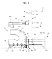
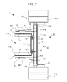
- Figs. 1 to 8B show an exemplary replacement transporting device according to the present invention, that is, a replacement transporting device 1.
- the replacement transporting device 1 includes a beam transporting carrier 10 (serving as a first transporting carrier section) and a transfer transporting carrier 20 (serving as a second transporting carrier section).
- the replacement transporting device 1 is formed as a replacement transporting device that is capable of transferring a warp beam 2 and a warp related device 3 to a loom as a result of connecting and integrating the beam transporting carrier 10 and the transfer transporting carrier 20 with each other.
- the replacement transporting device 1 is formed such that the beam transporting carrier 10 and the transfer transporting carrier 20 can be separated (disconnected) from each other.
- the beam transporting carrier 10 is described.
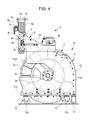
- the beam transporting carrier 10 has the structure shown in Figs. 4 and 5 , and includes a pair of side walls 11 and 11 for supporting the warp beam 2 and the warp related device 3, a horizontal beam 12 that connects both side walls 11 and 11, and four wheel units 13 that are provided so as to be mounted on lower surfaces of the corresponding side walls 11.
- Figs. 4 and 5 show a state in which the warp beam 2 and the warp related device 3 are mounted on the beam transporting carrier 10.
- Fig. 4 and 5 show a state in which the warp beam 2 and the warp related device 3 are mounted on the beam transporting carrier 10.
- Fig. 4 and 5 show a state in which the warp beam 2 and the warp related device 3 are mounted on the beam transporting carrier 10.
- Fig. 4 and 5 show a state in which the warp beam 2 and the warp related device 3 are mounted on the beam transporting carrier 10.
- Fig. 4 and 5 show a state in which the warp beam 2 and the warp related device 3 are mounted on the beam
- the warp related device 3 in a unitary state is mounted on the beam transporting carrier 10.
- each side wall 11 includes a side plate 11a (which is a principal portion) and a bottom plate 11b that is mounted on the side plate 11a.
- each side wall 11 is provided such that its side plate 11a stands in a vertical direction. Accordingly, in the description below, a direction along the vertical direction in which each wall plate 11a is oriented when it is provided on the beam transporting carrier 10 is defined as a height direction of each wall plate 11a, and a direction that is orthogonal to the height direction is defined as a width direction of each wall plate 11a along a wall surface.
- Each bottom plate 11b is formed of an elongated rectangular plate material having a uniform thickness.
- the dimension of each bottom plate 11b in a longitudinal direction thereof (that is, a long-side direction of the rectangular shape) is the same as the dimension of the lower end of each wall plate 11a in the width direction. While each bottom plate 11b is oriented in a direction orthogonal to its corresponding wall plate 11a with its plate thickness direction being set in the height direction, each bottom plate 11b is secured to its corresponding wall plate 11a with each bottom plate 11b being in contact with a lower end surface (a lower surface) of its corresponding wall plate 11a.
- each bottom plate 11b in the width direction with respect to its corresponding wall plate 11a with each bottom plate 11b being secured to its corresponding wall plate 11a (secured state) is such that the positions of both edges of the bottom plate 11b in the longitudinal direction corresponds to the positions of both ends of the lower end of the wall plate 11a in the width direction.
- each bottom plate 11b is in contact with the lower surface of its corresponding wall plate 11a at an intermediate position in a direction that is orthogonal to the longitudinal direction (a short-side direction of the rectangular shape).
- a reinforcing rib 11c is mounted on its corresponding side wall 11 at, of two side ends in the width direction thereof, a side end opposite to a side where its corresponding insertion path 11a2 opens so as to be provided on both sides of its corresponding wall plate 11a and its corresponding bottom plate 11b (see Fig. 5 ).
- the horizontal beam 12 is secured to both side walls 11 and 11 with a side edge in a direction orthogonal to a longitudinal direction of one of the end portions of the horizontal beam 12 in the longitudinal direction of the bottom plate 11b of each side wall 11 being made to correspond with a side edge of the bottom plate 11b adjacent to the corresponding end portion.
- the one of the end portions is provided at the side of its corresponding wall plate 11a where the rib 11c is provided in the width direction.
- the horizontal beam 12 is such that its longitudinal direction is oriented in a direction that is orthogonal to the width direction of the wall plate 11a of each side wall 11.
- the width direction of both wall plates 11a and 11a is orthogonal to the longitudinal direction of the horizontal beam 12.
- both side walls 11 and 11 are such that their wall plates 11a and 11a are parallel to each other and are symmetrically disposed with respect to the center of the horizontal beam 12 in the longitudinal direction.
- the bottom surfaces of the bottom plates 11b of the corresponding side walls 11 are in contact with the top surface of the horizontal beam 12. That is, the bottom plates 11b and 11b of the corresponding side walls 11 and 11 having a uniform plate thickness are positioned in the same plane.
- two wheel units 13 having the same structure are mounted on the bottom surface of the bottom plate 11b of each side wall 11.
- the warp beam 2 that is mounted on the beam transporting carrier 10 and transported includes a cylindrical barrel 2b and a pair of flanges 2c and 2c that are fitted to and mounted on the barrel 2b.
- the warp beam 2 has a structure in which a mounting position of one of the flanges 2c with respect to the barrel 2b is changeable along an axial direction of the barrel 2b such that weaving of fabrics having different weaving widths can be performed.
- the barrel 2b between the flanges 2c and 2c becomes a winding shaft 2a around which a warp is wound.
- the bearings 2d and 2d at the two ends of the warp beam 2 are set in a state in which they are positioned outwardly of the wall plates 11a and 11 a of the two side walls 11 and 11 of the beam transporting carrier 10.
- the warp related device 3 that is mounted on and transported by the beam transporting carrier 10 is transported in a unitary state (see Fig. 4 ). More specifically, in the embodiment, after the plurality of heald frames 3a, the dropper device 3b, and the reed 3c of the warp related device 3 have been transferred to the loom, they are supported by a frame member 4, which forms part of frames of the loom, and are made unitary. With the heald frames 3a, the dropper device 3b, and the reed 3c being made unitary, they are mounted on the beam transporting carrier 10 and are transferred to the loom as they are.
- the frame member 4 includes a pair of side plates 4a and 4a that are secured to the left and right frames of the loom after the transfer, with the pair of side plates 4a and 4a being connected to each other by a beam member 4b. With the two side plates 4a and 4a opposing each other in a plate thickness direction thereof, they are connected to each other by the beam member 4b.
- a horizontal direction (a front-back direction) that is orthogonal to the plate thickness direction being made to correspond with a front-back direction of the loom (that is, the direction in which a warp extends while the warp is set)
- the two side plates 4a and 4a are set on the frames of the loom.
- the side plates 4a are formed for being set on the frames of the loom, and include corresponding mounting portions 4c.
- the mounting portions 4c are prismatic members. Each member is mounted on a surface of its corresponding side plate 4a (outer surface) that is opposite to a surface of the corresponding side plate 4a (inner surface) opposing the other one of the side plates 4a in such a manner as to extend in the front-back direction.
- the side walls 4a are set on the frames of the loom with the outer surfaces of the side walls 4a being in contact with inner surfaces of the frames of the loom (that is, surfaces of the loom at the side of the center of the loom) and with the lower surfaces of the mounting portions 4c being mounted on top surfaces of the frames of the loom.
- the side plates 4a are secured to the frames of the loom.
- the frame member 4 is set in a state in which it is mounted on the frames of the loom.
- the outer surfaces of the two side plates 4a and 4a contact the inner surfaces of the corresponding frames of the loom. Therefore, the interval between the outer surfaces of the corresponding side plates 4a and 4a that are connected to each other by the beam member 4b of the frame member 4 (that is, the interval in the longitudinal direction of the beam member 4b) is substantially the same as the interval between the left and right frames of the loom.
- the side plates 4a are formed for mounting the frame member 4 on the beam transporting carrier 10, and include securing portions 4e.
- each securing portion 4e is a prismatic member having a groove extending in a longitudinal direction of the securing portion 4e.
- Each securing portion 4e is mounted at a lower end of the inner surface of its corresponding side plate 4a so as to extend in the front-back direction, and such that the groove opens in a downward direction.
- the frame member 4 is mounted (placed) on the beam transporting carrier 10 by engaging the grooves of the securing portions 4e of the corresponding side plates 4a and 4a with top ends of the corresponding side walls 11 (wall plates 11a) of the beam transporting carrier 10.
- the interval between the side walls 11 and 11 of the beam transporting carrier 10 is in correspondence with the length of the barrel 2b of the warp beam 2 that is mounted on the beam transporting carrier 10. Therefore, with the securing portions 4e and 4e being mounted on the corresponding side walls 4a, the interval between the grooves are in correspondence with the interval between the side walls 11 and 11 of the beam transporting carrier 10.
- the frame member 4 is such that each heald frame guide 5 for guiding an up-down movement of its corresponding heald frame 3a when weaving is carried out at the loom is supported by its corresponding side plate 4a through a corresponding supporting shaft 5a while each heald frame guide 5 is position at the inner surface of its corresponding side plate 4a.
- the frame member 4 is such that a pair of guide plates (that is, a front guide plate 6a and a rear guide plate 6b) are supported by the beam member 4b.
- the pair of guide plates are provided so as to sandwich the plurality of heald frames 3a for preventing vibration in a thickness direction (the front-back direction) of each heald frame 3a when weaving is carried out at the loom.
- the rear guide plate 6b is supported by the front guide plate 6a, mounted on the beam member 4b, through a shaft 6c.
- the aforementioned heald frame guides 5 and guide plates 6a and 6b have known structures that are generally used in a loom.
- the heald frame guides 5, the guide plates 6a and 6b, the beam member 4b, etc. are secured to the loom.
- these members are unitary along with the warp related device 3, and are transferred to the loom.
- the plurality of heald frames 3a of the warp related device 3 are supported by the frame member 4 with two side portions (side stays) of each heald frame 3a engaging with the corresponding heald frame guides 5 and 5 supported by the frame member 4 and being sandwiched by the pair of guide plates 6a and 6b in the front-back direction.
- the plurality of heald frames 3a are supported by the frame member 4 while a stave of each heald frame 3a is made to hang down by using, for example, two or more rods (not shown) mounted on the beam member 4b of the frame member 4 so as to extend in the front-back direction.
- the dropper device 3b is supported by the frame member 4 (the side plates 4a and 4a) by placing both ends of the dropper device 3b on top surfaces of the side plates 4a and 4a of the frame member 4 so as to form a bridge between the side plates 4a and 4a.
- the positions in the front-back direction of the dropper device 3b on the frame member 4 are such that their positions in relation to the positions of the heald frame guides 5 and 5 (the heald frames 3a) supported by the frame member 4 correspond to those in relation to the loom in the front-back direction.
- the warp related device 3 that is made unitary by using the frame member 4 as described above is transferred as it is to the loom, and the side plates 4a and 4a of the frame member 4 are secured at the predetermined mounting positions at the frames of the loom, to dispose the heald frames 3a and the dropper device 3b where they should be provided at the loom in the front-back direction.
- the side plates 4a and 4a of the frame member 4 function as they are as part of the frames of the loom.
- the reed 3c is supported by a plurality of reed holding tools 4f that are mounted at positions at the beam members 4b of the frame member 4 so as to be separated from each other in a longitudinal direction of the beam member 4b. Therefore, after the frame member 4 (the side plates 4a and 4a) has been mounted on the frames of the loom, the reed 3c is brought down from the frame member 4 (the reed holding tools 4f), and is mounted at predetermined setting positions at the loom.
- the heald frames 3a are set in a state in which they are connected to and supported by a driving mechanism of a shedding device.
- the height position of each heald frame guide 5 is determined on the basis of the supporting position at each side plate 4a of the frame member 4. Therefore, the supporting positions of the heald frame guides 5 in the height direction with respect to the mounting portions 4c at the side plates 4a and 4a are set such that the heald frame guides 5 are set at desired height positions at the loom with the frame member 4 being mounted on the frames of the loom.
- the dropper device 3b is used with the dropper device 3b being mounted on the side plates 4a and 4a functioning as the frames of the loom. Therefore, the dimension up to the top surfaces of the mounting portions 4c at the side plates 4a and 4a where the dropper device 3b is placed in the height direction is set such that the dropper device 3b is set at a desired height position at the loom with the frame member 4 being mounted on the frames of the loom.
- the transfer transporting carrier 20 includes a carrier section 30, serving as moving means, and a transferring mechanism 40 for transferring the warp related device 3 to the loom. Accordingly, the transfer transporting carrier 20 includes the transferring mechanism 40, and has the function of transferring the warp related device 3. More specifically, each of these portions has the following structure.
- the carrier section 30 includes two box-shaped bodies 31a and 31b and a connecting beam 32 that connects the two bodies 31a and 31b to each other.
- the bodies 31a and 31b each have a rectangular parallelepiped shape having a cutaway portion. With one end surface of the body 31a and one end surface of the body 31b being parallel to and opposing each other, the bodies 31a and 31b are connected to each other by the connecting beam 32 extending between the bodies 31a and 31b.
- the dimension of the connecting beam 32 in a longitudinal direction thereof, that is, the interval between the two bodies 31a and 31b is larger than the interval between the wall plates 11a and 11a of the corresponding side walls 11 and 11 of the beam transporting carrier 10.
- Each of the bodies 31a and 31b includes three wheels 31w.
- the wheels 31w of each body 31a and the wheels 31w of each body 31b are symmetrically disposed in a direction orthogonal to the longitudinal direction of the connecting beam 32. More specifically, if a direction that is parallel to the longitudinal direction of the connecting beam 32 at the bodies 31a and 31b is defined as a front-back direction of the bodies 31a and 31b and the body 31a (31b) is defined as being at the front (back) with respect to the body 31b (31a), and if a direction that is orthogonal to the front-back direction in a horizontal plane is defined as a transverse direction of the bodies 31a and 31b, the front body 31a includes two (a pair of) wheels 31w and 31w, which are separated from each other in the transverse direction at corresponding positions at the back side in the front-back direction, and one wheel 31w, which is provided at the center in the transverse direction at the front side in the front-back direction.
- each of the bodies 31a and 31b is formed such that the front-back direction and the transverse direction are set in the horizontal direction.
- the pair of back wheels 31w and 31w at the front body 31a and the pair of front wheels 31w and 31w at the back body 31b are, similarly to the wheel units 13 at the beam transporting carrier 10, casters and are rotatable in any direction.
- a driving motor (not shown) for driving the wheels 31w is built in each of the bodies 31a and 31b.
- the front wheel 31w at the front body 31a and the back wheel 31w at the back body 31b are drive wheels that are driven by the corresponding driving motor.
- the wheels 31w that are driven by the corresponding driving motor are called drive wheels 31wd.
- the connecting beam 32 is a beam member having a substantially square shape in cross section in a direction orthogonal to the longitudinal direction.
- two of the four peripheral surfaces (that is, the top surface and the bottom surface) of the connecting beam 32 extending in the longitudinal direction being parallel to the transverse direction at the bodies 31a and 31b, one end of the connecting beam 32 in the longitudinal direction thereof is secured to the end surface of the front body 31a opposing the back body 31b, and the other end of the connecting beam 32 in the longitudinal direction is secured to the end surface of the back body 31b opposing the front body 31 a, to connect the bodies 31 a and 31b to each other. Therefore, with the carrier section 30 being placed on a horizontal floor, in the carrier section 30, the top surface of the connecting beam 32 extends such that the longitudinal direction thereof and a direction orthogonal to the longitudinal direction are set in the horizontal direction.
- An operating rod 33 for operating the carrier section 30 is provided at the back body 31b of the carrier section 30 so as to extend upward from a back top surface.
- the operating rod 33 is provided with a plurality of operating buttons (not shown).
- the plurality of operating buttons include a movement button for starting the movement of the carrier section 30 (transfer transporting carrier 20) and a stop button for stopping the movement. By operating the movement button, the driving of the drive wheels 31wd by the driving motor is started. By operating the stop button, the driving of the drive wheels 31wd is stopped.
- the plurality of operating buttons also include a button for operating, for example, an arm unit 42 of the transferring mechanism 40 (described later).
- the orientation of the operating rod 33 and the orientation of each drive wheel 31wd change in correspondence with each other. That is, when the orientation of the operating rod 33 is changed, the orientation of each drive wheel 31wd changes to the same orientation as that of the operating rod 33. Therefore, by operating the operating rod 33, the direction of movement of the carrier section 30 (transfer transporting carrier 20) that is moving can be changed. Accordingly, in the embodiment, the drive wheels 31wd also function as steerable wheels.
- the operating rod 33 functions as a steering wheel.
- the transferring mechanism 40 is provided by being supported by the connecting beam 32 of the carrier section 30 having the above-described structure.
- the transferring mechanism 40 includes a frame member 41 that is supported by the connecting beam 32 of the carrier section 30 and the arm unit 42 that is supported by the frame member 41. More specifically, each of these portions has the following structure.
- the frame member 41 has a shape formed by combining four prismatic beam members into a rectangular shape.
- the frame member 41 includes a base portion 41a that is provided on the connecting beam 32, a pair of columns 41 b and 41b that stand in an upward direction from the base portion 41a, and a beam 41c that connects top ends of the corresponding columns 41b and 41b.
- the frame member 41 is such that the columns 41b and 41b that are orthogonal to the base portion 41a stand on corresponding end portions in the longitudinal direction of the top surface of the base portion 41a that is provided on the connecting beam 32.
- the frame member 41 is formed by, by using the beam 41c, connecting the top ends of the columns 41b and 41b that stand on the base portion 41a in this way.
- the interval between the pair of columns 41 b and 41b of the frame member 41 (the dimension of the base portion 41a in the longitudinal direction thereof) is larger than the interval between the wall plates 11 a and 11 a of the corresponding side walls 11 and 11 of the beam transporting carrier 10.
- driving means for driving the frame member 41 in the longitudinal direction of the connecting beam 32 along the connecting beam 32 is provided between the frame member 41 and the carrier section 30.
- the position of the frame member 41 on the connecting beam 32 is adjustable in a range of the difference between the dimension of the connecting beam 32 and the dimension of the base portion 41a in the longitudinal direction.
- the driving means for example, a structure in which a rack is provided at a lower surface of the base portion 41a of the frame member 41, a driving motor is provided at the connecting beam 32, and a pinion that is mounted on an output portion of the driving motor is engaged with the rack may be used.
- the arm unit 42 is supported by and provided at the frame member 41 having the above-described structure.
- the arm unit 42 includes a support beam 42a that is supported by the frame member 41, a pair of drive portions 42b and 42b that are mounted on the support beam 42a, a pair of arms 42c and 42c that are supported by the support beam 42a by using the drive portions 42b and 42b, and supporting portions 42d and 42d that are mounted on the corresponding arms 42c and 42c.
- the support beam 42a includes a prismatic beam material.
- the dimension of the support beam 42a in a longitudinal direction thereof is slightly larger than the interval between the pair of columns 41 b and 41b of the frame member 41.
- the support beam 42a has grooves 42a1 in two respective end portions in the longitudinal direction thereof.
- the support beam 42a engages with the columns 41 b and 41 b (frame member 41) so as to be slidable only in directions of extension (up-down directions) of the columns 41 b and 41b with the columns 41 b being fitted to the corresponding grooves 42a1.
- driving means that drive (displace) the support beam 42a for regulating the position of the support beam 42a in the up-down directions and for adjusting the position of the support beam 42a in the up-down direction is provided between the frame member 41 and the support beam 42a.
- each driving means for example, a ball screw mechanism using a driving motor as a driving source may be used.
- ball screw shafts in the ball screw mechanism are each represented by symbol 41d, and the driving motors, serving as the driving sources, are each represented by symbol 41e.
- the pair of drive portions 42b and 42b are mounted on the support beam 42a.
- Each of the drive portions 42b has the shape of a box.
- Each of the drive portions 42b is supported by the support beam 42a with each drive portion 42b being in contact with, of the peripheral surfaces of the support frame 42 extending in the longitudinal direction, one of two peripheral surfaces (support surface 42a2) that is parallel to the up-down direction.
- Driving means that drive the drive portions 42b are each provided between the support beam 42a and the corresponding drive portion 42b.
- Each drive portion 42b is driven so as to move in the longitudinal direction of the support beam 42a by the driving means.
- each driving means for example, a structure in which a driving motor is built in each drive portion 42b, a rack is provided at the rail of the support beam 42a, and a pinion that is mounted on an output shaft of the driving motor is engaged with the rack may be used.
- Each arm 42c is mounted on a surface of its corresponding drive portion 42b opposite to the surface of its corresponding drive portion 42b that contacts the support surface 42a2 of the support beam 42a so as to extend away from the support beam 42a. That is, the arm unit 42 includes the pair of arms 42c and 42c supported by the support beam 42a by using the corresponding drive portions 42b and 42b, with each arm 42c extending in the width direction of the bodies 31a and 31b of the carrier section 30.
- each arm 42c is formed from a fluid pressure cylinder (such as a hydraulic cylinder), and is expandable and contractible as a whole as a result of drive rods 42c2 advancing and retreating with respect to a base portion 42c1 in a direction of extension of the drive rods 42c2 by the action of fluid pressure (hydraulic pressure).
- a fluid pressure cylinder such as a hydraulic cylinder
- the dimension in the longitudinal direction of the support beam 42a (support surface 42a2) that supports the arms 42c by using the drive portions 42b is slightly larger than the interval between the pair of columns 41 b and 41b of the frame member 41.
- the interval between the pair of columns 41 b and 41b is larger than the interval between the pair of side walls 11 and 11 (wall plates 11a and 11a) of the beam transporting carrier 10. Therefore, in the longitudinal direction of the support beam 42a, the pair of arms 42c and 42c may be disposed with the interval between the pair of arms 42c and 42c being greater than the interval between the pair of side walls 11 and 11 (wall plates 11 a and 11 a) of the beam transporting carrier 10.
- the pair of arms 42c and 42c do not support the warp related device 3
- the pair of arms 42c and 42c are separated from each other by such a large interval.
- the supporting portions 42d and 42d are mounted on the end portions of the corresponding arms 42c that are opposite to the side of the drive portions 42b.
- the supporting portions 42d support the above-described unitary warp related device 3 (frame member 4), includes plate support members 42d1 as principal members, with the support members 42d1 being mounted on the corresponding arms 42c (drive rods 42c2) by corresponding mounting brackets 42d2.
- the plate support members 42d1 of the corresponding supporting portions 42d are supported by the corresponding mounting brackets 42d2, mounted on the corresponding drive rods 42c2, with each supporting member 42d1 extending downward at the side (inner side) that opposes the other arm 42c at the drive rod 42c2 of its corresponding arm 42c.
- each supporting portion 42d has two support holes 42d3 and 42d3 for hanging and supporting the warp related device 3.
- Each side plate 4a of the frame member 4 that supports the warp related device 3 includes two supporting pins 4d and 4d that are engageable with the two support holes 42d3 and 42d2 of the corresponding support member 42d1.
- the relationship between each support hole 42d3 and its corresponding supporting pin 4d is as shown in Figs. 7A and 7B .
- the support holes 42d3 and the supporting pins 4d are described in more detail below.
- each support hole 42d3 and 42d3 of the corresponding support member 42d1 are formed at different positions in the up-down direction and the direction of extension of the corresponding arm 42c, and extend through the corresponding support member 42d1 in a plate thickness direction thereof.
- each support hole 42d3 has a shape that is similar to that formed by combining two circles, with an upper large diameter portion and a lower small diameter portion being connected to each other with a linear connecting portion.
- the supporting pins 4d are provided at the frame member 4 such that two supporting pins 4d protrude from the outer surface (the side of the corresponding mounting portion 4c) of each side plate 4a and are engageable with the support holes 42d3 of the corresponding support member 42d1 as described above. That is, the relationship between the positions of the two supporting pins 4d and 4d in the up-down direction and the front-back direction of the frame member 4 is the same as the relationship between the positions of the two support holes 42d3 and 42d3 in each support member 42d1.
- Each supporting pin 4d includes a shaft 4d1 that stands from the outer surface of the corresponding side plate 4a and a head 4d2 that is provided at an end portion of the corresponding shaft 4d1 opposite to the outer surface and that has a disc shape whose diameter is larger than that of the corresponding shaft 4d1.
- the diameter of the head 4d2 of each supporting pin 4d allows the head 4d2 to pass through the large diameter portion of the corresponding support hole 42d3 and does not allow the head 4d2 to pass through the small diameter portion of the corresponding support hole 42d3.
- the diameter of each shaft 4d1 is in correspondence with the diameter of each small diameter portion.
- the length of each shaft 4d1 in an axial direction thereof is in correspondence with the plate thickness of each support member 42d.
- each support member 42d1 opposing the outer surface of the corresponding side plate 4a of the frame member 4, and, as viewed from the axial direction of each supporting pin 4d, with the positions of the large diameter portions of the two support holes 42d3 and 42d3 of each support member 42d1 being aligned with the positions of the two supporting pins 4d and 4d of each side plate 4a, the support members 42d1 are displaced towards the corresponding side plates 4a in the axial direction, so that each supporting pin 4d is inserted in the large diameter portion of the support hole 42d3 in the corresponding support member 42d1.
- Each support member 42d1 is displaced in the axial direction by displacing the corresponding arm 42c as a result of driving the corresponding drive portion 42b of the arm unit 42.
- each supporting member 42d1 is displaced upward, so that the shaft 4d1 of each supporting pin 4d is set in a state in which it is positioned in the small diameter portion of the corresponding support hole 42d3 (state shown by an alternate long and two short dashes line in Fig. 7B ).
- the diameter of the head 4d2 of each supporting pin 4d does not allow the head 4d2 to pass through the small diameter portion of the corresponding support hole 42d3.
- the head 4d2 of each supporting pin 4d retains the corresponding supporting pin 4d with respect to the corresponding support hole 42d3, that is, the head 4d2 of each supporting pin 4d restricts relative displacement between the corresponding supporting pin 4d and the corresponding support member 42d1 in the axial direction. Therefore, the frame member 4 is stopped in an engaged state with the pair of supporting portions 42d of the arm unit 42 of the transfer transporting carrier 20.
- the transferring mechanism 40 includes connecting devices 50 that connect the transfer transporting carrier 20 and the beam transporting carrier 10 to each other.
- two connecting devices 50 are supported by the frame member 41 of the transferring mechanism 40 while being separated from each other in the longitudinal direction of the base portion 41 a of the frame member 41.
- Each connecting device 50 includes a connecting portion 51 as a principal portion, and is provided with each connecting portion 51 being supported by a corresponding bracket 52 (see Fig. 8 ).
- Each bracket 52 is mounted on the surface of the corresponding base portion 41a at the same side as the support surface 42a2 of the support beam 42a of the arm unit 42 so as to extend downward.
- Each connecting portion 51 is mounted on a lower end of the corresponding bracket 52, and, in the up-down direction, is provided at substantially the same height as the horizontal beam 12 of the beam transporting carrier 10.
- each connecting portion 51 includes an outer frame 51a that is mounted on the corresponding bracket 52, a sliding portion 51b that is slidably provided with respect to the corresponding outer frame 51a, and a connecting tool 51c that is supported by the corresponding sliding portion 51 b.
- the outer frame 51a is substantially C-shaped in cross section where a groove 51a2 is formed in a rectangular parallelepiped member.
- the groove 51a2 opens at both top and bottom sides and at a side that is opposite to the side where the corresponding bracket 52 is mounted.
- the groove 51a2 of each outer frame 51a guides the sliding of the corresponding sliding portion 51b and functions as a guide groove.
- Each sliding portion 51b is a member in the form of a housing, and has a cross-sectional shape that allows it to be received by the guide groove 51a2 of the corresponding outer frame 51a.
- Each sliding portion 51b is provided in a state in which it is received by the guide groove 51a2 of the corresponding outer guide 51a, and is slidable in the corresponding guide groove 51a2 in up-down directions.
- the dimension of each sliding portion 51b in the up-down direction is smaller than the dimension of each outer frame 51a (guide groove 51a2) in the up-down direction.
- Each sliding portion 51b is slidable in the corresponding guide groove 51 a2 in the up-down directions as described above.
- a bottom surface defining each guide groove 51a2 (surface that is parallel to the surface of the corresponding bracket 52 on which the corresponding outer frame 51a is mounted) is provided with a rail 51a1 that is formed in the up-down direction.
- a surface of each sliding portion 51b that contacts the bottom surface defining the corresponding guide groove 51a2 is provided with a recess 51b1 that is fitted to the corresponding rail 51a1.
- the aforementioned sliding of each sliding portion 51b in the up-down directions is also guided by the corresponding rail 51a1 that is fitted to the corresponding recess 51a1.
- driving means (not shown) is provided between each outer frame 51a and the corresponding sliding portion 51b.
- Each sliding portion 51b is driven so as to be slid and displaced in the up-down directions by the corresponding driving means.
- each driving means for example, a structure in which a rack is provided at the rail 51a1 of each outer frame 51a, a driving motor is built in each sliding portion 51b, and a pinion that is mounted on an output shaft of the driving motor is engaged with the corresponding rack may be used.
- each connecting device 50 the sliding portion 51b and the securing portion 51c2 of the connecting tool 51c are accommodated in the guide groove 51a2; and only the hook 51c1 of the connecting tool 51c protrudes from the guide groove 51a2 (opposite mounting surface 51a3 of the outer frame 51 a that is opposite to the surface that is mounted on the bracket 52).
- two connecting windows 12a are provided similarly to the connecting devices 50 of the transporting carrier 20 (transferring mechanism 40).
- the two connecting windows 12a are provided at the horizontal beam 12 of the beam transporting carrier 10.
- the connecting tools 51c of the corresponding connecting devices 50 engage with the connecting windows 12a.
- each connecting window 12a is formed so as to extend through a peripheral wall 12b of the hollow horizontal beam 12 that is opposite to a peripheral wall that opposes the corresponding wheel units 13.
- the two connecting windows 12a and 12a are symmetrically disposed with respect to the center of the horizontal beam 12 in the longitudinal direction thereof, and are separated apart from each other such that the interval between the two connecting windows 12a and 12a is the same as the interval between the two connecting devices 50 and 50 of the transfer transporting carrier 20.
- the width of each connecting window 12a in an up-down direction thereof is slightly larger than that of each hook 51 c1 of the connecting tool 51c of the corresponding connecting device 50 in the up-down direction.
- the transfer transporting carrier 20 and the beam transporting carrier 10 are connected to each other. More specifically, as shown in Fig. 8B , prior to connecting the transfer transporting carrier 20 and the beam transporting carrier 10 to each other, the transfer transporting carrier 20 and the beam transporting carrier 10 are disposed in a state in which the connecting devices 50 oppose the horizontal beam 12 and the base portions 41a of the frame member 41 are parallel to the horizontal beam 12.
- the transfer transporting carrier 20 and the beam transporting carrier 10 are set in a state in which the positions of the two connecting devices 50 and 50 and the positions of the two connecting windows 12a and 12a are aligned with each other.
- the center of each base portion 41a (frame member 41) and the center of the horizontal beam 12 are caused to be in alignment with each other.
- each connecting device 50 of the transfer transporting carrier 20 the position of the sliding portion 51b in the outer frame 51 a is set such that the hook 51 c1 of the connecting tool 51c is positioned within the corresponding connecting window 12a of the beam transporting carrier 10 in the up-down direction.
- the arms 42c and 42c (support members 42d1 and 42d1) of the arm unit 42 that are positioned between the bodies 31a and 31b of the transfer transporting carrier 20 are disposed such that the interval between the arms 42c and 42c is larger than the interval between the side walls 11 and 11 (wall plates 11a and 11a) of the beam transporting carrier 10. Therefore, in the above-described arrangement, in the longitudinal direction of the horizontal beam 12, the beam transporting carrier 10 is set in a state in which it is positioned between the arms 42c and 42c of the transfer transporting carrier 20.
- the transfer transporting carrier 20 is moved towards the beam transporting carrier 10 such that the distance between the transfer transporting carrier 20 and the beam transporting carrier 10 is reduced.
- the connecting devices 50 are positioned closest to the beam transporting carrier 10.
- the warp drawing-in device by using the drawing-in device, as mentioned above, the warp T that has been drawn out from the warp beam 2 is drawn into the dropper device 3b, the plurality of heald frames 3a, and the reed 3c in the warp related device 3 (mounted on the beam transporting carrier 10) in that order.
- the warp drawing-in device is also called a drawing machine. Since the device itself is known, specific descriptions and illustrations of the structure of the device itself are not given.
- the beam transporting carrier 10 moves while transporting the warp beam 2 and the warp related device 3 towards a storage place, such as a preparation room, in a textile factory, from the warp drawing-in device.
- the beam transporting carrier 10 on which the warp beam 2 and the warp related device 3 are mounted is temporarily stored in the storage place.
- a plurality of the beam transporting carriers 10 on which warp beams 2 and warp related devices 3 are mounted are stored. That is, instead of, for example, using a general storage shed that is set in a textile factory, the warp beams 2 and the warp related devices 3 that are unified are stored by the plurality of beam transporting carriers 10.
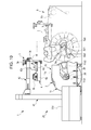
- the warp related device 3 As mentioned above, the warp related device 3 according to the embodiment that is supported by the arm unit 42 of the replacement transporting device 1 is made unitary by the frame member 4. As shown in Fig. 10 , by mounting the frame member 4 at predetermined mounting position at frames 8b of the loom 8, the heald frames 3a and the dropper device 3b are disposed where they should be provided at the loom 8. Accordingly, in transferring the warp related device 3 to the loom 8, first, in the state in which the replacement transporting device 1 has moved to the position where it transfers the warp beam 2 to the loom 8 as mentioned above, the arms 42c of the arm unit 42 are extended, so that the frame member 4 is set in a state in which it is positioned above the mounting position at the loom 8 (frames 8b).
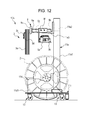
- a first transporting carrier section 10A shown in Fig. 12 is one in which a first supporting portion 11d that supports a warp beam 2 and a second supporting portion 11e that supports a warp related device 3 are provided on a carrier 11f with wheel units 13.
- the first supporting portion 11d includes a pair of supporting walls 11d1 and 11d1 (only one of them is shown in Fig. 12 ) in the form of side plates that are separated from and oppose each other.
- the second supporting portion 11e includes a pair of supports 11e1 and 11e1 and a catching portion 11e3.
- the beam transporting carrier 10 serving as the first transporting carrier section is capable of entering the take-up portion of the warping device in the warp preparing process and allows the warp beam 2 to be directly transferred between it and the warping device.
- the first transporting carrier section of the replacement transporting device according to the present invention is not limited to such a structure.
- the first transporting carrier section of the replacement transporting device according to the present invention may have a structure in which it is not capable of entering the take-up portion of the warping device.
- the warp beam 2 may be transferred between the first transporting carrier section and the warping device by rolling the warp beam 2 along a floor surface with the first transporting carrier section being disposed away from the warping device.
- the supporting tool 9 in the example shown in Fig. 12 , in the first transporting carrier section 10A, by the catching portion 11e3 mounted on the beam member 11e2 that connects the supports 11e1 and 11e1 to each other, the supporting tool 9 is supported while being mounted on the catching portion 11e3; and, in the second transporting carrier section, as in the embodiment, the supporting tool 9 is supported at the transferring mechanism by the supporting pins 9f and 9f provided at the supporting tool 9.
- the illustrated supporting tool 9 is formed by connecting a pair of side frames 9a and 9a (only one of them is shown in Fig. 12 ) to a pair of horizontal beams 9b and 9b.
- the illustrated supporting tool 9 includes a pair of hooks 9c, each of which is connected to one end of its corresponding side frame 9a, that support the corresponding head frames 3a, a reed holding tool 9d that is caught by the hooks 9c and that supports the reed 3c, and a pair of supporting members 9e, each of which is mounted on an intermediate portion of its corresponding side frame 9a, that support the dropper device 3b.
- the way in which the warp related device 3 is supported is not limited to the way in which the heald frames 3a and the dropper device 3b are supported together by a common supporting member, such as the frame member 4 as in the embodiment, or the supporting tool 9.
- a common supporting member such as the frame member 4 as in the embodiment, or the supporting tool 9.
- the heald frames 3a and the dropper device 3b are independently mounted on (supported by) the first transporting carrier section; and, as the first transporting carrier section and the second transporting carrier section are connected to each other, the second transporting carrier section independently supports the heald frames 3a and the dropper device 3b.
- the heald frames 3a and the dropper device 3b may be independently supported by the second supporting portion 11e.
- the arms 42e of the arm unit 42A may be provided with supporting portions 42m that support the heald frames 3a and the supporting portions 42h that support the dropper device 3b.
- a hoist or the like that is provided at the drawing-in device transfers the warp related device 3 that has been prepared near the drawing-in device to the beam transporting carrier 10 on which the warp beam 2 is mounted.
- the following may be performed. That is, after the second transporting carrier section (transfer transporting carrier 20) of the replacement transporting device, where the warp beam 2 and the warp related device 3 have been brought down from the loom for loom change, has been separated from the first transporting carrier section (beam transporting carrier 10), the second transporting carrier section may be moved up to the drawing-in device with the second transporting carrier section continuing supporting the warp related device 3. Then, the warp related device 3 supported by the second transporting carrier section may be transferred to the first transporting carrier section.
- the second transporting carrier section (transfer transporting carrier 20) with a clamping mechanism that clamps from two sides the side walls 11 and 11 (wall plates 11a and 11a) of the first transporting carrier section (beam transporting carrier 10), and to connect the first transporting carrier section and the second transporting carrier section to each other by the clamping mechanism. More specifically, as in a replacement transporting device 1A shown in Fig.
- a base portion 41 a of a frame member 41 of a second transporting carrier section 20A with a pair of clamping members 53 and 53 that are symmetrically provided apart from each other in a longitudinal direction of the base portion 41a, and to clamp the first transporting carrier section by the pair of clamping members 53 and 53.
- the clamping members 53 in the illustrated example are provided so as to be movable in the longitudinal direction of the base portion 41a, and are driven so as to be displaced in the longitudinal direction by driving means (not shown). Therefore, by driving the clamping members 53 so as to be displaced toward each other in the longitudinal direction, it is possible to connect the first transporting carrier section 10 and the second transporting carrier section 20A to each other by clamping the first transporting carrier section 10.
- first transporting carrier section and the second transporting carrier section may be connected to each other by using, for example, a structure in which the first transporting carrier section are provided with shaft portions that protrude outward from the corresponding wall plates at the two sides and the second transporting carrier section is provided with connecting tools including hooks that are capable of catching the corresponding shaft portions of the first transporting carrier section.
- the present invention is not limited to the above-described practical forms, and can be variously modified without departing from the gist of the present invention.
Landscapes
- Engineering & Computer Science (AREA)
- Textile Engineering (AREA)
- Auxiliary Weaving Apparatuses, Weavers' Tools, And Shuttles (AREA)
Applications Claiming Priority (2)
| Application Number | Priority Date | Filing Date | Title |
|---|---|---|---|
| JP2014118277 | 2014-06-09 | ||
| JP2014141866A JP2016014210A (ja) | 2014-06-09 | 2014-07-10 | 織機用の交換品搬送装置、及びその交換品搬送装置を用いたワープビームの搬送方法 |
Publications (1)
| Publication Number | Publication Date |
|---|---|
| EP2955257A1 true EP2955257A1 (fr) | 2015-12-16 |
Family
ID=53525048
Family Applications (1)
| Application Number | Title | Priority Date | Filing Date |
|---|---|---|---|
| EP15170543.1A Withdrawn EP2955257A1 (fr) | 2014-06-09 | 2015-06-03 | Dispositif de transport de remplacement pour métier à tisser et procédé de transport d'ensouple utilisant ledit dispositif |
Country Status (3)
| Country | Link |
|---|---|
| EP (1) | EP2955257A1 (fr) |
| JP (1) | JP2016014210A (fr) |
| CN (2) | CN204702277U (fr) |
Cited By (1)
| Publication number | Priority date | Publication date | Assignee | Title |
|---|---|---|---|---|
| CN109576876A (zh) * | 2019-01-31 | 2019-04-05 | 山东日发纺织机械有限公司 | 织机及运输车系统及其定位抱紧装置 |
Families Citing this family (5)
| Publication number | Priority date | Publication date | Assignee | Title |
|---|---|---|---|---|
| CN110395566A (zh) * | 2019-07-30 | 2019-11-01 | 诺伯特智能装备(山东)有限公司 | 一种磁导向agv自动经轴上料车 |
| CN112176493A (zh) * | 2020-09-29 | 2021-01-05 | 际华三五四二纺织有限公司 | 一种用于喷气织机综框的挂钩结构 |
| CN112623820B (zh) * | 2020-12-18 | 2023-06-02 | 东莞士格电子集团有限公司 | 一种卷绕装置 |
| CN112707207B (zh) * | 2020-12-18 | 2023-06-06 | 东莞士格电子集团有限公司 | 一种卷绕设备 |
| CN115418770B (zh) * | 2022-09-27 | 2023-06-30 | 射阳县杰力纺织机械有限公司 | 整经机的自动进出经轴的装置 |
Citations (4)
| Publication number | Priority date | Publication date | Assignee | Title |
|---|---|---|---|---|
| JPH02264042A (ja) * | 1989-04-03 | 1990-10-26 | Toyota Autom Loom Works Ltd | ワープビーム空転防止装置 |
| EP0592807A1 (fr) * | 1992-10-14 | 1994-04-20 | Lindauer Dornier Gesellschaft M.B.H | Dispositif pour amener un système de changement de chaîne adapté à une machine à tisser |
| EP0620304A1 (fr) * | 1993-04-16 | 1994-10-19 | Sulzer RàTi Ag | Méthode et dispositif pour changer l'article |
| JPH09111612A (ja) | 1995-10-13 | 1997-04-28 | Toyota Autom Loom Works Ltd | 織機における機仕掛け装置 |
-
2014
- 2014-07-10 JP JP2014141866A patent/JP2016014210A/ja active Pending
-
2015
- 2015-06-01 CN CN201520367510.2U patent/CN204702277U/zh not_active Expired - Fee Related
- 2015-06-01 CN CN201510292829.8A patent/CN105314438A/zh active Pending
- 2015-06-03 EP EP15170543.1A patent/EP2955257A1/fr not_active Withdrawn
Patent Citations (5)
| Publication number | Priority date | Publication date | Assignee | Title |
|---|---|---|---|---|
| JPH02264042A (ja) * | 1989-04-03 | 1990-10-26 | Toyota Autom Loom Works Ltd | ワープビーム空転防止装置 |
| EP0592807A1 (fr) * | 1992-10-14 | 1994-04-20 | Lindauer Dornier Gesellschaft M.B.H | Dispositif pour amener un système de changement de chaîne adapté à une machine à tisser |
| JPH06235147A (ja) | 1992-10-14 | 1994-08-23 | Lindauer Dornier Gmbh | たて糸交換装置を織機に適正に入れるための装置 |
| EP0620304A1 (fr) * | 1993-04-16 | 1994-10-19 | Sulzer RàTi Ag | Méthode et dispositif pour changer l'article |
| JPH09111612A (ja) | 1995-10-13 | 1997-04-28 | Toyota Autom Loom Works Ltd | 織機における機仕掛け装置 |
Cited By (1)
| Publication number | Priority date | Publication date | Assignee | Title |
|---|---|---|---|---|
| CN109576876A (zh) * | 2019-01-31 | 2019-04-05 | 山东日发纺织机械有限公司 | 织机及运输车系统及其定位抱紧装置 |
Also Published As
| Publication number | Publication date |
|---|---|
| CN204702277U (zh) | 2015-10-14 |
| JP2016014210A (ja) | 2016-01-28 |
| CN105314438A (zh) | 2016-02-10 |
Similar Documents
| Publication | Publication Date | Title |
|---|---|---|
| EP2955257A1 (fr) | Dispositif de transport de remplacement pour métier à tisser et procédé de transport d'ensouple utilisant ledit dispositif | |
| CN113602865B (zh) | 一种筒织机下引卷筒收料装置 | |
| CN111776808B (zh) | 一种带有布匹自动运输装置的织造生产线 | |
| CN117125123A (zh) | 供丝卷装输送台车 | |
| CN216444795U (zh) | 一种具有断纱报警功能的全自动收卷机 | |
| US5450880A (en) | Insertion vehicle and carriage for changing a fabric to be woven on a loom | |
| US3280442A (en) | Warp-thread stand for textile drawing-in machines | |
| CN220664519U (zh) | 一种挂纱机用的挂纱平台转向装置 | |
| CN214004934U (zh) | 一种吹吸式纱线清洗装置 | |
| WO2015040516A1 (fr) | Appareil d'introduction automatique de fibre optique et procédé d'introduction de fibre | |
| JP2001508840A (ja) | 経糸取替え装置 | |
| CN212450068U (zh) | 一种玻璃纤维编织带缠线轮绕丝装置 | |
| CN115418778B (zh) | 一种带检测功能的剑杆织机 | |
| US12180623B2 (en) | Device for handling harness elements and drawing-in machine | |
| CN110552103A (zh) | 分绞机平行拉纱用织轴传动装置 | |
| CN220264541U (zh) | 一种纺织用可拆卸的收卷辊 | |
| JPH0716855A (ja) | カレンダのロール交換方法及び装置 | |
| CN112981654A (zh) | 一种带引线功能的整经机 | |
| CN212292160U (zh) | 一种布料打卷机 | |
| CN223423003U (zh) | 一种具有存放功能的验布机 | |
| CN220665559U (zh) | 一种方便运输经轴的分条整经机 | |
| CN213647533U (zh) | 一种铁丝生产用放置架 | |
| CN121977695A (en) | Sock weaving color detection device and detection method | |
| CN210529158U (zh) | 一种多梭塑料圆织机 | |
| US3205815A (en) | Textile roller printing machine |
Legal Events
| Date | Code | Title | Description |
|---|---|---|---|
| PUAI | Public reference made under article 153(3) epc to a published international application that has entered the european phase |
Free format text: ORIGINAL CODE: 0009012 |
|
| AK | Designated contracting states |
Kind code of ref document: A1 Designated state(s): AL AT BE BG CH CY CZ DE DK EE ES FI FR GB GR HR HU IE IS IT LI LT LU LV MC MK MT NL NO PL PT RO RS SE SI SK SM TR |
|
| AX | Request for extension of the european patent |
Extension state: BA ME |
|
| STAA | Information on the status of an ep patent application or granted ep patent |
Free format text: STATUS: THE APPLICATION IS DEEMED TO BE WITHDRAWN |
|
| 18D | Application deemed to be withdrawn |
Effective date: 20160617 |