EP2955262B1 - Waschmaschine - Google Patents
Waschmaschine Download PDFInfo
- Publication number
- EP2955262B1 EP2955262B1 EP15171170.2A EP15171170A EP2955262B1 EP 2955262 B1 EP2955262 B1 EP 2955262B1 EP 15171170 A EP15171170 A EP 15171170A EP 2955262 B1 EP2955262 B1 EP 2955262B1
- Authority
- EP
- European Patent Office
- Prior art keywords
- machine according
- cable
- drum
- axis
- rotation
- Prior art date
- Legal status (The legal status is an assumption and is not a legal conclusion. Google has not performed a legal analysis and makes no representation as to the accuracy of the status listed.)
- Active
Links
Images




Classifications
-
- D—TEXTILES; PAPER
- D06—TREATMENT OF TEXTILES OR THE LIKE; LAUNDERING; FLEXIBLE MATERIALS NOT OTHERWISE PROVIDED FOR
- D06F—LAUNDERING, DRYING, IRONING, PRESSING OR FOLDING TEXTILE ARTICLES
- D06F37/00—Details specific to washing machines covered by groups D06F21/00 - D06F25/00
- D06F37/20—Mountings, e.g. resilient mountings, for the rotary receptacle, motor, tub or casing; Preventing or damping vibrations
- D06F37/22—Mountings, e.g. resilient mountings, for the rotary receptacle, motor, tub or casing; Preventing or damping vibrations in machines with a receptacle rotating or oscillating about a horizontal axis
-
- D—TEXTILES; PAPER
- D06—TREATMENT OF TEXTILES OR THE LIKE; LAUNDERING; FLEXIBLE MATERIALS NOT OTHERWISE PROVIDED FOR
- D06F—LAUNDERING, DRYING, IRONING, PRESSING OR FOLDING TEXTILE ARTICLES
- D06F37/00—Details specific to washing machines covered by groups D06F21/00 - D06F25/00
- D06F37/20—Mountings, e.g. resilient mountings, for the rotary receptacle, motor, tub or casing; Preventing or damping vibrations
-
- F—MECHANICAL ENGINEERING; LIGHTING; HEATING; WEAPONS; BLASTING
- F16—ENGINEERING ELEMENTS AND UNITS; GENERAL MEASURES FOR PRODUCING AND MAINTAINING EFFECTIVE FUNCTIONING OF MACHINES OR INSTALLATIONS; THERMAL INSULATION IN GENERAL
- F16F—SPRINGS; SHOCK-ABSORBERS; MEANS FOR DAMPING VIBRATION
- F16F7/00—Vibration-dampers; Shock-absorbers
- F16F7/14—Vibration-dampers; Shock-absorbers of cable support type, i.e. frictionally-engaged loop-forming cables
Definitions
- the present invention relates to a washing machine, and more particularly to a suspension system for the washing unit of a washing machine.
- the washing machines of the known type comprise essentially: a frame, a washing unit, a suspension system for the washing unit and a drive unit (see, for example, WO 94/04843 ).
- the frame is usually rigid and adapted to support the load of the suspension system, the drive unit, the washing unit and the load to be washed which is placed inside the washing unit.
- the washing unit comprises a washing tub and a rotating drum, the latter being moved in a known manner by the drive unit.
- the washing unit is connected to the frame by means of the suspension system which generally comprises springs and shock absorbers.
- the suspension system of the washing unit has the function of damping the vibrations due to the imbalance of the load inside the drum during its rotation.
- imbalance i.e. dynamic imbalance
- inertia forces may arise such that they generate an inertia torque orthogonal to the axis of rotation, not equal to zero.
- a vibratory movement also of a significant nature, is generated.
- the load to be washed is distributed in a random manner along the periphery of the rotating drum, causing an imbalance of the drum
- the vibrations in addition to generating a bothersome noise, may be very damaging for the mechanical strength of the machine components, i.e. suspension system and frame, to which they are transmitted.
- washing-machine manufacturers have therefore paid particular attention to these issues and over the years many types of shock-absorbing systems for the washing unit, of both the passive and active type, have been developed.
- the washing unit may for example be suspended from the top by means of springs and supported on the bottom by means of shock absorbers. Also known are versions in which the washing unit is not suspended by means of springs, the latter being included in the shock absorbers.
- the passive system absorbs the vibrations produced by the imbalance of the rotating washing unit.
- This type of system acts effectively only in certain intensity ranges of the vibrating movement. Therefore, for example, during transients due for example to the rotational start-up phase or in the case of a major imbalance in the load, these systems may not be effective for damping certain vibrational frequencies.
- the washing unit is connected to the frame for example by means of actuators controlled by an electronic control unit which, via suitable sensors (known per se to the person skilled in the art), detect the degree of imbalance and adapt the response of the actuators to the real forces which act on the washing unit.
- actuators controlled by an electronic control unit which, via suitable sensors (known per se to the person skilled in the art), detect the degree of imbalance and adapt the response of the actuators to the real forces which act on the washing unit.
- the present invention relates in particular to this technical sector namely that of industrial washing machines, it being clear however that reference to this sector is not exclusive, but that the principles of the present invention may be applied in an equal measure also to washing machines in general, for example for domestic use.
- washing machines of the prior art although widely used and popular, are not without drawbacks.
- the nature of the components which are used are such that the washing machines are easily prone to breakage and to the consequent replacement of damaged parts.
- shock absorbers which are usually of an oil-hydraulic nature, are particularly subject to wear and must be replaced after a give number of operating cycles or in any case every 3 to 4 years.
- the washing unit which is subject to the stresses described above, transmits intense vibrations to the frame and its electric and electronic components which may also be severely damaged.
- the object of the present invention is therefore to solve at least partially the drawbacks of the prior art.
- a first task of the present invention is to provide a machine with a structure which is simpler than that of the machines of the prior art.
- a second task of the present invention is to provide a machine which is less prone to wear of its mechanical parts than the machines of the prior art.
- the aim is to provide a washing machine which does not require continuous maintenance and continuous replacement of parts of the suspension system or the frame.
- the aim is to provide a machine which is more stable than the machines of the prior art, i.e. which does not allow a lot of movement of the washing unit at low speeds of rotations and which is more effective in damping the vibrations at high speeds of rotation.
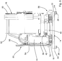
- the reference number 12 denotes an industrial washing machine according to the present invention.
- the washing machine 12 comprises a frame 14, on which a washing unit 16 and a drive unit 20 are mounted by means of a suspension system 18.
- the frame 14 comprises a base support 22 with a rectangular shape.
- the base support 22 may be formed by tubes with a square cross-section which are welded to each other at their ends so as to form a rectangle or a square supported at the corners of the base support by support feet 24 (for easier reference all the support feet are indicated by the reference number 24).
- Each support foot 24 may be provided with an angular fixing profile 26 comprising a surface adapted to be connected to the side surface of the support foot 24, and a surface, perpendicular to the former, provided with a hole for performing fixing to the ground or onto another structure.
- the frame 14 is designed to support the weight of the washing unit 16, the drive unit 20, the suspension system 18 and the weight of the laundry, the water and the detergent during washing.
- the washing unit 16 may be of a type known per se to the person skilled in the art.
- the washing unit comprises a tub 28 and a drum 29, which have a substantially cylindrical form with the axis of the cylinder coinciding with the axis of rotation of the drum 29.
- the drum 29 is mounted rotatably inside the tub.
- drum is an element known per se to the person skilled in the art it will not be further described.
- the axis of rotation is arranged in a direction substantially horizontal with respect to the surface on which the base support rests.
- the tub 28 comprises two opposite end faces 30, 32 and a side surface 34.
- a hatch 36 may be provided on a first end face 30 of the tub 28, this element being known per se in this type of machine and therefore not being further described. According to alternative embodiments, the hatch may also be provided on the side surface of the tub, for example directed upwards.
- Washing unit and drive unit are provided on a support structure 38.
- the support structure 38 comprises a base 40 on which the tub 28 and a motor 42 forming part of the drive unit 20 are fixed in a known manner.
- a vertical structure 44 rigidly connected to the base 40, may also be provided.
- the vertical structure 44 is provided on the opposite side to the first end face 30 on which the hatch 36 is provided.
- a connection between drum 29 and drive unit 20 is provided in the region of the second end face, indicated by the reference number 32 in the attached figures, and the vertical structure 44.
- a shaft 46 connected in a manner known per se to the drum 29, projects through the tub 28 and may rest on a seat provided on the vertical structure 44.
- a radial bearing may be provided between seat and shaft 46 of the motor 42.
- the shaft 46 receives the movement for rotation about its axis from the motor 42.
- movement transmission means 48 are provided between shaft 46 and motor 42.
- the movement transmission means 48 comprise a first pulley 50 keyed onto the shaft 46, a second pulley 52 of the motor 42 and a belt 54 which engages with the pulleys 50, 52.
- the motor 42 may be connected directly to the drum without the need to provide the movement transmission means 48 described above.
- the suspension system denoted overall by the reference number 18 is provided between the support structure 38 and the frame 14.
- the suspension system 18 comprises metal-cable shock absorbers, denoted generically by the reference number 56.
- the metal-cable shock absorbers are shown in the larger scale view of Figure 7 .
- the metal-cable shock absorbers 56 comprise a shock absorber element 58 comprising at least one cable wound so as to form at least one coil 60, preferably a plurality of coaxial coils 60, and mounting brackets 62, 64.
- the shock absorbing properties are present not only in a plane perpendicular to the axis of the coils, but also in non-perpendicular planes and also along the direction of the axis of the coils.
- the basic properties of this type of shock absorber since they are known to the person skilled in the art, will not be described further.
- the shock absorber element 58 may be formed by a single cable wound in a spiral in which the coils 60 are locked in position by means of the mounting brackets 62, 64.
- the shock absorber element 58 may be obtained using sections of cable.
- a cable section may be wound so as to form a coil 60 or a group of coils 60.
- the cable may be formed by strands in turn formed by wires.
- the cable may have a thickness of between 10 and 20 mm. Moreover, it may have a diameter of the coils ranging between 50 and 150 mm
- the number of coils for each shock absorber element 58 may range between 4 and 10.
- the material from which the cable is made consists of steel.
- the cable may be galvanized with a metal core.
- Each mounting bracket 62, 64 may comprise two parts 66, 68 and 70, 72 facing each other. Moreover, each part 66, 68 and 70, 72 may comprise seats having substantially the shape of a semi-circle.
- Each pair of parts 66, 68 and 70, 72 is fixed, for example by means of fixing screws 74, so that the cable is locked in position.
- the mounting brackets 62, 64 are provided at diametrically opposite points.
- the mounting brackets 62, 64 are used to fix the cable shock absorber to the frame 14 and to the support structure 38.
- the cable shock absorber is fixed to the base and the base support 22.
- At least one metal-cable shock absorber per side, is provided between the base support 22 and base 40, along their portions parallel to the axis of rotation of the drum.
- two metal-cable shock absorbers per side, may be provided between the base support 22 and base 40, along their portions parallel to the axis of rotation of the drum.
- At least one cable shock absorber may be provided between base support 20 and base 40 along their front portion perpendicular to the axis of rotation of the drum.
- the mounting brackets 62, 64 of the shock absorbers may be arranged along a direction inclined with respect to the base support.
- the brackets are provided so that the mounting bracket 64 connected to the base support 22 is in a more external position than the mounting bracket 62 connected to the base 40.
- the plane passing through the two mounting brackets 62, 64, denoted by the reference number 76 in Figure 4 , of each cable shock absorber is inclined towards the axis of rotation of the drum
- the inclination of the plane 76 passing through the two mounting brackets 62, 64 of each cable shock absorber is inclined towards the axis of rotation of the drum at an angle of between 0° and 45°, indicated by ⁇ in Figure 4 .
- the shock absorber positioned on the front side of the base support 22 may have support brackets 62, 64 arranged along a direction orthogonal to the axis of rotation of the drum.
- Figures 9-11 show an alternative embodiment of the present invention, which envisages four shock absorber elements 56, two for each side, between base support 22 and base 40, along their portions parallel to the axis of rotation of the drum.
- the shock absorbing elements 56 may be inclined at least in two directions.
- the inclination of the plane 76 passing through the two mounting brackets 62, 64 of each cable shock absorber may be inclined, relative to the vertical, towards the axis of rotation of the drum, at an angle of between 0° and 45°, indicated by ⁇ in Figure 10 .
- each shock absorber element is inclined with respect a plane perpendicular to the axis of rotation of the drum at an angle of between 70° and 90°, indicated by ⁇ in Figure 11 .
- the shock absorber element arranged in the front position may not be provided.
- the system according to the present invention eliminates substantially the movement, reducing the friction, sliding and wear of all the mechanical parts.
- suspension system 18 is activated only at certain frequencies, and in particular at the washing frequencies of between 7 and 12 Hz it keeps the system rigid.
- the potential load imbalance may be increased by up to 15% without having to interrupt the cycle and reactivate the centrifuge.
- the current shock absorbers are of the oil-hydraulic type and have an average life of 3 to 4 years.
- the suspension system 18 according to the present invention has a practically infinite duration and in any case does not required the use of oils.
- the design is relatively simply since it consists of a steel cable forming coils locked between steel plates.
- shock absorber systems for example, to shock absorber systems of the known type, such as oil-hydraulic shock absorbers or springs, are possible.
Landscapes
- Engineering & Computer Science (AREA)
- Textile Engineering (AREA)
- Main Body Construction Of Washing Machines And Laundry Dryers (AREA)
Claims (13)
- Waschmaschine mit einem Rahmen (14), sowie einer Wascheinheit (16) und einer Antriebseinheit (20) für die Wascheinheit (16), die mittels eines Federungssystems (18) mit dem Rahmen verbunden sind,
dadurch gekennzeichnet, dass das Federungssystem (18) Metalldraht-Stoßdämpfer (56) aufweist, die ein Stoßdämpferelement (58) aufweisen, das wiederum zumindest einen Draht, der so gewickelt ist, dass zumindest eine Spule (60) gebildet ist, und Montagehalter (62, 64) aufweist. - Waschmaschine gemäß Anspruch 1, gekennzeichnet durch eine Stützstruktur (38), die eine Basis (40) aufweist, an der die Wascheinheit (16) und die Antriebseinheit (20) angeordnet sind, wobei der Rahmen (14) eine Basisstütze aufweist, wobei die Basis (40) mit der Basisstütze (22) mittels des Federungssystems (18) verbunden ist.
- Maschine gemäß einem der vorherigen Ansprüche,
dadurch gekennzeichnet, dass das Stoßdämpferelement (58) durch einen einzigen Draht gebildet ist, der spiralförmig gewickelt ist, wobei die Spulen (60) mittels der Montagehalter (62, 64) ortsfest verriegelt sind. - Maschine gemäß Anspruch 1, dadurch gekennzeichnet, dass der Draht eine Dicke zwischen 10 und 20 mm hat.
- Maschine gemäß Anspruch 1, dadurch gekennzeichnet, dass jeder Montagehalter (62, 64) zwei Teile (66, 68, 70, 72) aufweist, die einander gegenüberliegen, wobei jedes Teil (66, 68; 70, 72) Sitze aufweist, die im Wesentlichen die Form eines Halbkreises für den Draht haben, wobei die Teile mittels Schrauben ortsfest verriegelt sind.
- Maschine gemäß Anspruch 2, dadurch gekennzeichnet, dass zwischen der Basisstützen (22) und der Basis (40) entlang deren Abschnitten parallel zu der Drehachse der Trommel zumindest ein Metalldraht-Stoßdämpfer für jeden Abschnitt vorgesehen ist.
- Maschine gemäß dem vorherigen Anspruch, dadurch gekennzeichnet, dass zwischen der Basisstütze (22) und der Basis (40) entlang deren Abschnitten parallel zu der Drehachse der Trommel zwei Metalldraht-Stoßdämpfer für jeden Abschnitt vorgesehen sind.
- Maschine entweder gemäß Anspruch 6 oder 7, dadurch gekennzeichnet, dass die Montagehalter (62, 64) des Stoßdämpfers, die an den Abschnitten parallel zu der Drehachse der Trommel angeordnet sind, entlang einer Richtung angeordnet sein können, die hinsichtlich der Basisspitze (22) geneigt ist.
- Maschine gemäß Anspruch 8, dadurch gekennzeichnet, dass der Montagehalter (64), der mit der Basisspitze (22) verbunden ist, an einer weiter äußeren Position ist als der Montagehalter (62), der mit der Basis (40) verbunden ist.
- Maschine gemäß Anspruch 9, dadurch gekennzeichnet, dass eine Ebene (67), die durch die zwei Montagehalter (62, 64) des jeweiligen Metalldraht-Stoßdämpfers hindurchtritt, die an den Seitenabschnitten positioniert sind, zu der Drehachse der Trommel geneigt ist.
- Maschine gemäß Anspruch 10, dadurch gekennzeichnet, dass die Neigung der Ebene (76), die durch die zwei Montagehalter (62, 64) des jeweiligen Metalldraht-Stoßdämpfers hindurchtritt, zu der Drehachse der Trommel in einem Winkel zwischen 0° und 45° geneigt ist.
- Maschine gemäß einem der Ansprüche 8 bis 11, dadurch gekennzeichnet, dass die Längsachse (53) des jeweiligen Stoßdämpferelementes relativ zu einer Ebene geneigt ist, die senkrecht zu der Drehachse der Trommel steht, und zwar in einem Winkel zwischen 70° und 90°.
- Maschine gemäß einem der Ansprüche 6 bis 12, dadurch gekennzeichnet, dass zumindest ein Metalldraht-Stoßdämpfer zwischen der Basisspitze (22) und der Basis (40) entlang deren Frontabschnitten senkrecht zu der Drehachse der Trommel angeordnet ist.
Applications Claiming Priority (1)
| Application Number | Priority Date | Filing Date | Title |
|---|---|---|---|
| ITTV20140079 | 2014-06-10 |
Publications (2)
| Publication Number | Publication Date |
|---|---|
| EP2955262A1 EP2955262A1 (de) | 2015-12-16 |
| EP2955262B1 true EP2955262B1 (de) | 2017-01-25 |
Family
ID=51494452
Family Applications (1)
| Application Number | Title | Priority Date | Filing Date |
|---|---|---|---|
| EP15171170.2A Active EP2955262B1 (de) | 2014-06-10 | 2015-06-09 | Waschmaschine |
Country Status (1)
| Country | Link |
|---|---|
| EP (1) | EP2955262B1 (de) |
Families Citing this family (5)
| Publication number | Priority date | Publication date | Assignee | Title |
|---|---|---|---|---|
| JP2020103565A (ja) * | 2018-12-27 | 2020-07-09 | 青島海爾洗衣机有限公司QingDao Haier Washing Machine Co.,Ltd. | ドラム式洗濯機 |
| CN110588496A (zh) * | 2019-09-25 | 2019-12-20 | 重庆真测科技股份有限公司 | 一种车载工业ct/dr系统主机减振系统 |
| CN113123060B (zh) * | 2019-12-31 | 2024-06-18 | 合肥海尔滚筒洗衣机有限公司 | 一种双滚筒洗衣机 |
| CN113279195A (zh) * | 2020-02-19 | 2021-08-20 | 青岛海尔滚筒洗衣机有限公司 | 一种洗衣机 |
| CN116254681A (zh) * | 2021-12-09 | 2023-06-13 | 青岛胶州海尔洗涤电器有限公司 | 一种洗衣机底部防护结构 |
Family Cites Families (4)
| Publication number | Priority date | Publication date | Assignee | Title |
|---|---|---|---|---|
| FR1369294A (fr) * | 1963-03-09 | 1964-08-07 | Ensemble élastique capable d'absorber des vibrations et des chocs ou de transmettre des couples et des moments, ou de réaliser ces deux fonctions | |
| IT226869Z2 (it) * | 1992-08-20 | 1997-07-22 | Camossi Carlo | Dispositivo elastico a cavo metallico ed antivibrazione per il supporto di un gruppo rotante |
| US5609328A (en) * | 1994-07-13 | 1997-03-11 | Vectra Technologies, Inc. | Pipe restraint |
| US6406011B1 (en) * | 2000-02-02 | 2002-06-18 | Enidine Incorporated | Wire rope isolator with pinned bar and method for making same |
-
2015
- 2015-06-09 EP EP15171170.2A patent/EP2955262B1/de active Active
Non-Patent Citations (1)
| Title |
|---|
| None * |
Also Published As
| Publication number | Publication date |
|---|---|
| EP2955262A1 (de) | 2015-12-16 |
Similar Documents
| Publication | Publication Date | Title |
|---|---|---|
| EP2955262A1 (de) | Waschmaschine | |
| JP2755567B2 (ja) | ドラム型洗濯機の洗濯槽 | |
| US20130118211A1 (en) | Drum washing machine | |
| US20120017646A1 (en) | Washing machine and controlling method thereof | |
| CN1312348C (zh) | 用于滚筒式洗衣机的减震器 | |
| KR101654054B1 (ko) | 세탁장치 | |
| JP2009095587A (ja) | ドラム式洗濯機 | |
| EP2504480B1 (de) | Wäschebehandlungsmaschine mit einer vibrationsdämpfungsvorrichtung | |
| CN107604588B (zh) | 一种滚筒洗衣机 | |
| CN110656468B (zh) | 具有不平衡补偿环的洗衣机 | |
| KR100459189B1 (ko) | 세탁기의 진동흡수장치 | |
| KR20110034029A (ko) | 드럼식 세탁기 | |
| JP2015043795A (ja) | ドラム式洗濯機 | |
| JP3234325B2 (ja) | 防振用ダンパの取付構造 | |
| CN106319857B (zh) | 滚筒洗衣机 | |
| KR20200076427A (ko) | 드럼세탁기용 댐퍼 | |
| JP2015043801A (ja) | ドラム式洗濯機 | |
| RU2469138C1 (ru) | Стиральная машина барабанного типа | |
| JP4941454B2 (ja) | ドラム式洗濯機 | |
| KR20100128655A (ko) | 세탁장치 및 그 제어방법 | |
| JP2007020992A (ja) | ドラム式洗濯機 | |
| US20140109628A1 (en) | Drum washing machine | |
| CN105378172A (zh) | 滚筒式洗衣机 | |
| CN219690104U (zh) | 一种减震装置以及采用该减震装置的洗衣机 | |
| KR101710388B1 (ko) | 세탁장치의 탈수행정 제어방법 |
Legal Events
| Date | Code | Title | Description |
|---|---|---|---|
| PUAI | Public reference made under article 153(3) epc to a published international application that has entered the european phase |
Free format text: ORIGINAL CODE: 0009012 |
|
| AK | Designated contracting states |
Kind code of ref document: A1 Designated state(s): AL AT BE BG CH CY CZ DE DK EE ES FI FR GB GR HR HU IE IS IT LI LT LU LV MC MK MT NL NO PL PT RO RS SE SI SK SM TR |
|
| AX | Request for extension of the european patent |
Extension state: BA ME |
|
| 17P | Request for examination filed |
Effective date: 20160614 |
|
| RBV | Designated contracting states (corrected) |
Designated state(s): AL AT BE BG CH CY CZ DE DK EE ES FI FR GB GR HR HU IE IS IT LI LT LU LV MC MK MT NL NO PL PT RO RS SE SI SK SM TR |
|
| GRAP | Despatch of communication of intention to grant a patent |
Free format text: ORIGINAL CODE: EPIDOSNIGR1 |
|
| INTG | Intention to grant announced |
Effective date: 20160817 |
|
| GRAS | Grant fee paid |
Free format text: ORIGINAL CODE: EPIDOSNIGR3 |
|
| STAA | Information on the status of an ep patent application or granted ep patent |
Free format text: STATUS: GRANT OF PATENT IS INTENDED |
|
| GRAA | (expected) grant |
Free format text: ORIGINAL CODE: 0009210 |
|
| STAA | Information on the status of an ep patent application or granted ep patent |
Free format text: STATUS: THE PATENT HAS BEEN GRANTED |
|
| AK | Designated contracting states |
Kind code of ref document: B1 Designated state(s): AL AT BE BG CH CY CZ DE DK EE ES FI FR GB GR HR HU IE IS IT LI LT LU LV MC MK MT NL NO PL PT RO RS SE SI SK SM TR |
|
| REG | Reference to a national code |
Ref country code: GB Ref legal event code: FG4D |
|
| REG | Reference to a national code |
Ref country code: CH Ref legal event code: EP |
|
| REG | Reference to a national code |
Ref country code: AT Ref legal event code: REF Ref document number: 864211 Country of ref document: AT Kind code of ref document: T Effective date: 20170215 |
|
| REG | Reference to a national code |
Ref country code: IE Ref legal event code: FG4D |
|
| REG | Reference to a national code |
Ref country code: DE Ref legal event code: R096 Ref document number: 602015001339 Country of ref document: DE |
|
| REG | Reference to a national code |
Ref country code: LT Ref legal event code: MG4D |
|
| REG | Reference to a national code |
Ref country code: NL Ref legal event code: MP Effective date: 20170125 |
|
| REG | Reference to a national code |
Ref country code: AT Ref legal event code: MK05 Ref document number: 864211 Country of ref document: AT Kind code of ref document: T Effective date: 20170125 |
|
| REG | Reference to a national code |
Ref country code: FR Ref legal event code: PLFP Year of fee payment: 3 |
|
| PG25 | Lapsed in a contracting state [announced via postgrant information from national office to epo] |
Ref country code: NL Free format text: LAPSE BECAUSE OF FAILURE TO SUBMIT A TRANSLATION OF THE DESCRIPTION OR TO PAY THE FEE WITHIN THE PRESCRIBED TIME-LIMIT Effective date: 20170125 |
|
| PG25 | Lapsed in a contracting state [announced via postgrant information from national office to epo] |
Ref country code: IS Free format text: LAPSE BECAUSE OF FAILURE TO SUBMIT A TRANSLATION OF THE DESCRIPTION OR TO PAY THE FEE WITHIN THE PRESCRIBED TIME-LIMIT Effective date: 20170525 Ref country code: LT Free format text: LAPSE BECAUSE OF FAILURE TO SUBMIT A TRANSLATION OF THE DESCRIPTION OR TO PAY THE FEE WITHIN THE PRESCRIBED TIME-LIMIT Effective date: 20170125 Ref country code: FI Free format text: LAPSE BECAUSE OF FAILURE TO SUBMIT A TRANSLATION OF THE DESCRIPTION OR TO PAY THE FEE WITHIN THE PRESCRIBED TIME-LIMIT Effective date: 20170125 Ref country code: HR Free format text: LAPSE BECAUSE OF FAILURE TO SUBMIT A TRANSLATION OF THE DESCRIPTION OR TO PAY THE FEE WITHIN THE PRESCRIBED TIME-LIMIT Effective date: 20170125 Ref country code: NO Free format text: LAPSE BECAUSE OF FAILURE TO SUBMIT A TRANSLATION OF THE DESCRIPTION OR TO PAY THE FEE WITHIN THE PRESCRIBED TIME-LIMIT Effective date: 20170425 Ref country code: GR Free format text: LAPSE BECAUSE OF FAILURE TO SUBMIT A TRANSLATION OF THE DESCRIPTION OR TO PAY THE FEE WITHIN THE PRESCRIBED TIME-LIMIT Effective date: 20170426 |
|
| PG25 | Lapsed in a contracting state [announced via postgrant information from national office to epo] |
Ref country code: PL Free format text: LAPSE BECAUSE OF FAILURE TO SUBMIT A TRANSLATION OF THE DESCRIPTION OR TO PAY THE FEE WITHIN THE PRESCRIBED TIME-LIMIT Effective date: 20170125 Ref country code: PT Free format text: LAPSE BECAUSE OF FAILURE TO SUBMIT A TRANSLATION OF THE DESCRIPTION OR TO PAY THE FEE WITHIN THE PRESCRIBED TIME-LIMIT Effective date: 20170525 Ref country code: AT Free format text: LAPSE BECAUSE OF FAILURE TO SUBMIT A TRANSLATION OF THE DESCRIPTION OR TO PAY THE FEE WITHIN THE PRESCRIBED TIME-LIMIT Effective date: 20170125 Ref country code: SE Free format text: LAPSE BECAUSE OF FAILURE TO SUBMIT A TRANSLATION OF THE DESCRIPTION OR TO PAY THE FEE WITHIN THE PRESCRIBED TIME-LIMIT Effective date: 20170125 Ref country code: RS Free format text: LAPSE BECAUSE OF FAILURE TO SUBMIT A TRANSLATION OF THE DESCRIPTION OR TO PAY THE FEE WITHIN THE PRESCRIBED TIME-LIMIT Effective date: 20170125 Ref country code: BG Free format text: LAPSE BECAUSE OF FAILURE TO SUBMIT A TRANSLATION OF THE DESCRIPTION OR TO PAY THE FEE WITHIN THE PRESCRIBED TIME-LIMIT Effective date: 20170425 Ref country code: LV Free format text: LAPSE BECAUSE OF FAILURE TO SUBMIT A TRANSLATION OF THE DESCRIPTION OR TO PAY THE FEE WITHIN THE PRESCRIBED TIME-LIMIT Effective date: 20170125 Ref country code: ES Free format text: LAPSE BECAUSE OF FAILURE TO SUBMIT A TRANSLATION OF THE DESCRIPTION OR TO PAY THE FEE WITHIN THE PRESCRIBED TIME-LIMIT Effective date: 20170125 |
|
| REG | Reference to a national code |
Ref country code: DE Ref legal event code: R097 Ref document number: 602015001339 Country of ref document: DE |
|
| PG25 | Lapsed in a contracting state [announced via postgrant information from national office to epo] |
Ref country code: EE Free format text: LAPSE BECAUSE OF FAILURE TO SUBMIT A TRANSLATION OF THE DESCRIPTION OR TO PAY THE FEE WITHIN THE PRESCRIBED TIME-LIMIT Effective date: 20170125 Ref country code: SK Free format text: LAPSE BECAUSE OF FAILURE TO SUBMIT A TRANSLATION OF THE DESCRIPTION OR TO PAY THE FEE WITHIN THE PRESCRIBED TIME-LIMIT Effective date: 20170125 Ref country code: RO Free format text: LAPSE BECAUSE OF FAILURE TO SUBMIT A TRANSLATION OF THE DESCRIPTION OR TO PAY THE FEE WITHIN THE PRESCRIBED TIME-LIMIT Effective date: 20170125 Ref country code: CZ Free format text: LAPSE BECAUSE OF FAILURE TO SUBMIT A TRANSLATION OF THE DESCRIPTION OR TO PAY THE FEE WITHIN THE PRESCRIBED TIME-LIMIT Effective date: 20170125 |
|
| PG25 | Lapsed in a contracting state [announced via postgrant information from national office to epo] |
Ref country code: DK Free format text: LAPSE BECAUSE OF FAILURE TO SUBMIT A TRANSLATION OF THE DESCRIPTION OR TO PAY THE FEE WITHIN THE PRESCRIBED TIME-LIMIT Effective date: 20170125 Ref country code: SM Free format text: LAPSE BECAUSE OF FAILURE TO SUBMIT A TRANSLATION OF THE DESCRIPTION OR TO PAY THE FEE WITHIN THE PRESCRIBED TIME-LIMIT Effective date: 20170125 |
|
| PLBE | No opposition filed within time limit |
Free format text: ORIGINAL CODE: 0009261 |
|
| STAA | Information on the status of an ep patent application or granted ep patent |
Free format text: STATUS: NO OPPOSITION FILED WITHIN TIME LIMIT |
|
| 26N | No opposition filed |
Effective date: 20171026 |
|
| PG25 | Lapsed in a contracting state [announced via postgrant information from national office to epo] |
Ref country code: MC Free format text: LAPSE BECAUSE OF FAILURE TO SUBMIT A TRANSLATION OF THE DESCRIPTION OR TO PAY THE FEE WITHIN THE PRESCRIBED TIME-LIMIT Effective date: 20170125 |
|
| PG25 | Lapsed in a contracting state [announced via postgrant information from national office to epo] |
Ref country code: SI Free format text: LAPSE BECAUSE OF FAILURE TO SUBMIT A TRANSLATION OF THE DESCRIPTION OR TO PAY THE FEE WITHIN THE PRESCRIBED TIME-LIMIT Effective date: 20170125 |
|
| REG | Reference to a national code |
Ref country code: IE Ref legal event code: MM4A |
|
| PG25 | Lapsed in a contracting state [announced via postgrant information from national office to epo] |
Ref country code: LU Free format text: LAPSE BECAUSE OF NON-PAYMENT OF DUE FEES Effective date: 20170609 Ref country code: IE Free format text: LAPSE BECAUSE OF NON-PAYMENT OF DUE FEES Effective date: 20170609 |
|
| REG | Reference to a national code |
Ref country code: BE Ref legal event code: MM Effective date: 20170630 |
|
| REG | Reference to a national code |
Ref country code: FR Ref legal event code: PLFP Year of fee payment: 4 |
|
| PG25 | Lapsed in a contracting state [announced via postgrant information from national office to epo] |
Ref country code: BE Free format text: LAPSE BECAUSE OF NON-PAYMENT OF DUE FEES Effective date: 20170630 |
|
| PG25 | Lapsed in a contracting state [announced via postgrant information from national office to epo] |
Ref country code: MT Free format text: LAPSE BECAUSE OF NON-PAYMENT OF DUE FEES Effective date: 20170609 |
|
| REG | Reference to a national code |
Ref country code: CH Ref legal event code: PL |
|
| PG25 | Lapsed in a contracting state [announced via postgrant information from national office to epo] |
Ref country code: LI Free format text: LAPSE BECAUSE OF NON-PAYMENT OF DUE FEES Effective date: 20180630 Ref country code: CH Free format text: LAPSE BECAUSE OF NON-PAYMENT OF DUE FEES Effective date: 20180630 |
|
| PG25 | Lapsed in a contracting state [announced via postgrant information from national office to epo] |
Ref country code: HU Free format text: LAPSE BECAUSE OF FAILURE TO SUBMIT A TRANSLATION OF THE DESCRIPTION OR TO PAY THE FEE WITHIN THE PRESCRIBED TIME-LIMIT; INVALID AB INITIO Effective date: 20150609 |
|
| PG25 | Lapsed in a contracting state [announced via postgrant information from national office to epo] |
Ref country code: CY Free format text: LAPSE BECAUSE OF FAILURE TO SUBMIT A TRANSLATION OF THE DESCRIPTION OR TO PAY THE FEE WITHIN THE PRESCRIBED TIME-LIMIT Effective date: 20170125 |
|
| PG25 | Lapsed in a contracting state [announced via postgrant information from national office to epo] |
Ref country code: MK Free format text: LAPSE BECAUSE OF FAILURE TO SUBMIT A TRANSLATION OF THE DESCRIPTION OR TO PAY THE FEE WITHIN THE PRESCRIBED TIME-LIMIT Effective date: 20170125 |
|
| GBPC | Gb: european patent ceased through non-payment of renewal fee |
Effective date: 20190609 |
|
| PG25 | Lapsed in a contracting state [announced via postgrant information from national office to epo] |
Ref country code: TR Free format text: LAPSE BECAUSE OF FAILURE TO SUBMIT A TRANSLATION OF THE DESCRIPTION OR TO PAY THE FEE WITHIN THE PRESCRIBED TIME-LIMIT Effective date: 20170125 |
|
| PG25 | Lapsed in a contracting state [announced via postgrant information from national office to epo] |
Ref country code: GB Free format text: LAPSE BECAUSE OF NON-PAYMENT OF DUE FEES Effective date: 20190609 |
|
| PG25 | Lapsed in a contracting state [announced via postgrant information from national office to epo] |
Ref country code: AL Free format text: LAPSE BECAUSE OF FAILURE TO SUBMIT A TRANSLATION OF THE DESCRIPTION OR TO PAY THE FEE WITHIN THE PRESCRIBED TIME-LIMIT Effective date: 20170125 |
|
| P01 | Opt-out of the competence of the unified patent court (upc) registered |
Effective date: 20230517 |
|
| PGFP | Annual fee paid to national office [announced via postgrant information from national office to epo] |
Ref country code: DE Payment date: 20250627 Year of fee payment: 11 |
|
| PGFP | Annual fee paid to national office [announced via postgrant information from national office to epo] |
Ref country code: IT Payment date: 20250508 Year of fee payment: 11 |
|
| PGFP | Annual fee paid to national office [announced via postgrant information from national office to epo] |
Ref country code: FR Payment date: 20250625 Year of fee payment: 11 |