EP2955285B1 - Materialhandhabungsmaschine - Google Patents
Materialhandhabungsmaschine Download PDFInfo
- Publication number
- EP2955285B1 EP2955285B1 EP15169229.0A EP15169229A EP2955285B1 EP 2955285 B1 EP2955285 B1 EP 2955285B1 EP 15169229 A EP15169229 A EP 15169229A EP 2955285 B1 EP2955285 B1 EP 2955285B1
- Authority
- EP
- European Patent Office
- Prior art keywords
- arm
- pressure
- hydraulic
- material handling
- control system
- Prior art date
- Legal status (The legal status is an assumption and is not a legal conclusion. Google has not performed a legal analysis and makes no representation as to the accuracy of the status listed.)
- Active
Links
Images


Classifications
-
- E—FIXED CONSTRUCTIONS
- E02—HYDRAULIC ENGINEERING; FOUNDATIONS; SOIL SHIFTING
- E02F—DREDGING; SOIL-SHIFTING
- E02F3/00—Dredgers; Soil-shifting machines
- E02F3/04—Dredgers; Soil-shifting machines mechanically-driven
- E02F3/28—Dredgers; Soil-shifting machines mechanically-driven with digging tools mounted on a dipper- or bucket-arm, i.e. there is either one arm or a pair of arms, e.g. dippers, buckets
- E02F3/36—Component parts
- E02F3/42—Drives for dippers, buckets, dipper-arms or bucket-arms
- E02F3/43—Control of dipper or bucket position; Control of sequence of drive operations
- E02F3/435—Control of dipper or bucket position; Control of sequence of drive operations for dipper-arms, backhoes or the like
- E02F3/439—Automatic repositioning of the implement, e.g. automatic dumping, auto-return
-
- E—FIXED CONSTRUCTIONS
- E02—HYDRAULIC ENGINEERING; FOUNDATIONS; SOIL SHIFTING
- E02F—DREDGING; SOIL-SHIFTING
- E02F9/00—Component parts of dredgers or soil-shifting machines, not restricted to one of the kinds covered by groups E02F3/00 - E02F7/00
- E02F9/20—Drives; Control devices
- E02F9/22—Hydraulic or pneumatic drives
- E02F9/2221—Control of flow rate; Load sensing arrangements
-
- E—FIXED CONSTRUCTIONS
- E02—HYDRAULIC ENGINEERING; FOUNDATIONS; SOIL SHIFTING
- E02F—DREDGING; SOIL-SHIFTING
- E02F3/00—Dredgers; Soil-shifting machines
- E02F3/04—Dredgers; Soil-shifting machines mechanically-driven
- E02F3/28—Dredgers; Soil-shifting machines mechanically-driven with digging tools mounted on a dipper- or bucket-arm, i.e. there is either one arm or a pair of arms, e.g. dippers, buckets
- E02F3/30—Dredgers; Soil-shifting machines mechanically-driven with digging tools mounted on a dipper- or bucket-arm, i.e. there is either one arm or a pair of arms, e.g. dippers, buckets with a dipper-arm pivoted on a cantilever beam, i.e. boom
- E02F3/32—Dredgers; Soil-shifting machines mechanically-driven with digging tools mounted on a dipper- or bucket-arm, i.e. there is either one arm or a pair of arms, e.g. dippers, buckets with a dipper-arm pivoted on a cantilever beam, i.e. boom working downwardly and towards the machine, e.g. with backhoes
-
- E—FIXED CONSTRUCTIONS
- E02—HYDRAULIC ENGINEERING; FOUNDATIONS; SOIL SHIFTING
- E02F—DREDGING; SOIL-SHIFTING
- E02F3/00—Dredgers; Soil-shifting machines
- E02F3/04—Dredgers; Soil-shifting machines mechanically-driven
- E02F3/28—Dredgers; Soil-shifting machines mechanically-driven with digging tools mounted on a dipper- or bucket-arm, i.e. there is either one arm or a pair of arms, e.g. dippers, buckets
- E02F3/36—Component parts
- E02F3/42—Drives for dippers, buckets, dipper-arms or bucket-arms
- E02F3/425—Drive systems for dipper-arms, backhoes or the like
-
- E—FIXED CONSTRUCTIONS
- E02—HYDRAULIC ENGINEERING; FOUNDATIONS; SOIL SHIFTING
- E02F—DREDGING; SOIL-SHIFTING
- E02F9/00—Component parts of dredgers or soil-shifting machines, not restricted to one of the kinds covered by groups E02F3/00 - E02F7/00
- E02F9/20—Drives; Control devices
- E02F9/2025—Particular purposes of control systems not otherwise provided for
- E02F9/2029—Controlling the position of implements in function of its load, e.g. modifying the attitude of implements in accordance to vehicle speed
-
- E—FIXED CONSTRUCTIONS
- E02—HYDRAULIC ENGINEERING; FOUNDATIONS; SOIL SHIFTING
- E02F—DREDGING; SOIL-SHIFTING
- E02F9/00—Component parts of dredgers or soil-shifting machines, not restricted to one of the kinds covered by groups E02F3/00 - E02F7/00
- E02F9/20—Drives; Control devices
- E02F9/22—Hydraulic or pneumatic drives
- E02F9/2278—Hydraulic circuits
- E02F9/2285—Pilot-operated systems
-
- E—FIXED CONSTRUCTIONS
- E02—HYDRAULIC ENGINEERING; FOUNDATIONS; SOIL SHIFTING
- E02F—DREDGING; SOIL-SHIFTING
- E02F9/00—Component parts of dredgers or soil-shifting machines, not restricted to one of the kinds covered by groups E02F3/00 - E02F7/00
- E02F9/24—Safety devices, e.g. for preventing overload
-
- E—FIXED CONSTRUCTIONS
- E02—HYDRAULIC ENGINEERING; FOUNDATIONS; SOIL SHIFTING
- E02F—DREDGING; SOIL-SHIFTING
- E02F9/00—Component parts of dredgers or soil-shifting machines, not restricted to one of the kinds covered by groups E02F3/00 - E02F7/00
- E02F9/20—Drives; Control devices
- E02F9/22—Hydraulic or pneumatic drives
- E02F9/2221—Control of flow rate; Load sensing arrangements
- E02F9/2225—Control of flow rate; Load sensing arrangements using pressure-compensating valves
- E02F9/2228—Control of flow rate; Load sensing arrangements using pressure-compensating valves including an electronic controller
-
- F—MECHANICAL ENGINEERING; LIGHTING; HEATING; WEAPONS; BLASTING
- F15—FLUID-PRESSURE ACTUATORS; HYDRAULICS OR PNEUMATICS IN GENERAL
- F15B—SYSTEMS ACTING BY MEANS OF FLUIDS IN GENERAL; FLUID-PRESSURE ACTUATORS, e.g. SERVOMOTORS; DETAILS OF FLUID-PRESSURE SYSTEMS, NOT OTHERWISE PROVIDED FOR
- F15B2211/00—Circuits for servomotor systems
- F15B2211/30—Directional control
- F15B2211/315—Directional control characterised by the connections of the valve or valves in the circuit
- F15B2211/31552—Directional control characterised by the connections of the valve or valves in the circuit being connected to an output member and a return line
- F15B2211/31564—Directional control characterised by the connections of the valve or valves in the circuit being connected to an output member and a return line having multiple output members
-
- F—MECHANICAL ENGINEERING; LIGHTING; HEATING; WEAPONS; BLASTING
- F15—FLUID-PRESSURE ACTUATORS; HYDRAULICS OR PNEUMATICS IN GENERAL
- F15B—SYSTEMS ACTING BY MEANS OF FLUIDS IN GENERAL; FLUID-PRESSURE ACTUATORS, e.g. SERVOMOTORS; DETAILS OF FLUID-PRESSURE SYSTEMS, NOT OTHERWISE PROVIDED FOR
- F15B2211/00—Circuits for servomotor systems
- F15B2211/30—Directional control
- F15B2211/315—Directional control characterised by the connections of the valve or valves in the circuit
- F15B2211/3157—Directional control characterised by the connections of the valve or valves in the circuit being connected to a pressure source, an output member and a return line
- F15B2211/31588—Directional control characterised by the connections of the valve or valves in the circuit being connected to a pressure source, an output member and a return line having a single pressure source and multiple output members
-
- F—MECHANICAL ENGINEERING; LIGHTING; HEATING; WEAPONS; BLASTING
- F15—FLUID-PRESSURE ACTUATORS; HYDRAULICS OR PNEUMATICS IN GENERAL
- F15B—SYSTEMS ACTING BY MEANS OF FLUIDS IN GENERAL; FLUID-PRESSURE ACTUATORS, e.g. SERVOMOTORS; DETAILS OF FLUID-PRESSURE SYSTEMS, NOT OTHERWISE PROVIDED FOR
- F15B2211/00—Circuits for servomotor systems
- F15B2211/60—Circuit components or control therefor
- F15B2211/63—Electronic controllers
- F15B2211/6303—Electronic controllers using input signals
- F15B2211/6306—Electronic controllers using input signals representing a pressure
- F15B2211/6313—Electronic controllers using input signals representing a pressure the pressure being a load pressure
-
- F—MECHANICAL ENGINEERING; LIGHTING; HEATING; WEAPONS; BLASTING
- F15—FLUID-PRESSURE ACTUATORS; HYDRAULICS OR PNEUMATICS IN GENERAL
- F15B—SYSTEMS ACTING BY MEANS OF FLUIDS IN GENERAL; FLUID-PRESSURE ACTUATORS, e.g. SERVOMOTORS; DETAILS OF FLUID-PRESSURE SYSTEMS, NOT OTHERWISE PROVIDED FOR
- F15B2211/00—Circuits for servomotor systems
- F15B2211/60—Circuit components or control therefor
- F15B2211/665—Methods of control using electronic components
-
- F—MECHANICAL ENGINEERING; LIGHTING; HEATING; WEAPONS; BLASTING
- F15—FLUID-PRESSURE ACTUATORS; HYDRAULICS OR PNEUMATICS IN GENERAL
- F15B—SYSTEMS ACTING BY MEANS OF FLUIDS IN GENERAL; FLUID-PRESSURE ACTUATORS, e.g. SERVOMOTORS; DETAILS OF FLUID-PRESSURE SYSTEMS, NOT OTHERWISE PROVIDED FOR
- F15B2211/00—Circuits for servomotor systems
- F15B2211/70—Output members, e.g. hydraulic motors or cylinders or control therefor
- F15B2211/76—Control of force or torque of the output member
- F15B2211/761—Control of a negative load, i.e. of a load generating hydraulic energy
Definitions
- the present invention relates to a material handling machine.
- Known material handling machines such as excavators have a material handling arm assembly.
- the arm assembly may have an arm, known as a boom, pivotally mounted about a generally horizontal axis relative to a chassis of the machine.
- a further arm known as a dipper, may be attached to an end of the boom remote from the chassis and may be pivotable about a generally horizontal axis.
- a material handling implement such as a bucket may be pivotably mounted on an end of the dipper.
- the boom may be raised and lowered by operation of a first hydraulic ram.
- the dipper may be moveable relative to the boom by operation of a second hydraulic ram, the bucket may be moveable relative to the dipper by operation of a third hydraulic ram.
- US patent US 5,855,159 describes a hydraulic circuit for a boom cylinder in a hydraulic shovel.
- US patent US 7,490,421 B1 describes a method for producing ground surfaces and a hydraulic excavator having a lifting cylinder, a stem cylinder and a shovel cylinder.
- International patent application WO 2008/035509 A1 describes an actuator control system implementing adaptive flow control.
- a skilful operator In order to handle material, for example dig a trench, a machine operator must simultaneously operate all three hydraulic actuators and this is a skilful process.
- a skilful operator when digging a trench, will quickly be able to fill the bucket with material, lift bucket out of the trench and empty the bucket to one or other side of the vehicle.
- This excavation cycle time or loading cycle time is markedly affected by the initial penetration of the bucket into the ground. If the bucket penetrates too far into the ground then the bucket cannot be drawn through the ground to be filled. Conversely if the bucket does not penetrate far enough into the ground, then the bucket only half fills. Less well trained operators tend to operate at lower excavation/ loading cycle times.
- a material handling machine including:
- the system is capable of overriding and/or supplementing an input from the operator when the operator has set the arm height to low so as to automatically lift the arm, which in turn lifts the ground engaging implement thereby allowing the ground engaging implement to move through the ground in the event that the operator has set the arm height too low.
- the machine may be arranged such that when a pressure within a pressure chamber is less than the target pressure the control system operates the first hydraulic actuator to lower the arm to increase the force of engagement between the ground engaging implement and the ground.
- control system may override and/or supplement an input from an operator when the operator has set the arm height too high so as to automatically lower the arm thereby preventing only part filling of the ground engaging implement such as a bucket or the like.
- a material handling machine 10 including a chassis 12 and an operator cab 14.
- the operator cab is mounted on the chassis 12.
- Ground engaging transport means in the form of a pair of tracks 16 are provided to move the machine over the ground.
- Attached to the chassis is a arm assembly 18, the arm assembly includes a first arm in the form of a boom 20, a second arm in the form of a dipper 22 and a ground engaging implement in the form of a bucket 24.
- the boom 20 is pivotally mounted by pivot 26 to link 12A at a first end 20A of the boom.
- Link 12A is pivotally mounted at a generally vertical axis relative to the chassis 12.
- Pivot 26 is orientated horizontally.
- the dipper is pivotally mounted via pivot 28 to a second end 20B of the boom 20.
- Pivot 28 is orientated horizontally.
- the bucket is pivotally mounted via pivot 30 to an end 22B of dipper 22 remote from end 22A of dipper 22. Pivot 30 is orientated horizontally.
- a first hydraulic actuator in the form of a first hydraulic ram 32 has a first end 32A pivotally attached to the chassis 12 and a second end 32B pivotally attached to the boom part way between the first and second ends of the boom.
- a second hydraulic actuator in the form of a second hydraulic ram 34 has a first end 34A pivotally attached to the boom part way between the first and second ends of the boom and a second end 34B pivotally attached to the dipper proximate the first end 22A of the dipper.
- a third hydraulic actuator in the form of a third hydraulic ram 36 has a first end 36A pivotally attached to the dipper proximate the first end 22A of the dipper and a second end 36B pivotally attached to a linkage mechanism 38 proximate the second end of the dipper.
- the linkage mechanism 38 per se is known and simply converts extension and retraction movement of the third hydraulic ram 36 into rotary movement of the bucket 24 about pivot 30.
- Extension of the first hydraulic ram causes the boom to raise, and contraction of the first hydraulic ram causes lowering of the boom.
- Extension of the second ram causes the dipper to pivot in a clockwise direction (when viewing figure 2 ) about pivot 28, i.e. causes the boom to move in a "dipper in” direction, and retraction of the second hydraulic ram 34 causes the dipper to move in an anticlockwise direction when viewing figure 2 about pivot 28, i.e. in a "dipper out” direction.
- Extension of the third hydraulic ram 36 causes the bucket 24 to move in a clockwise direction about pivot 30, i.e. in a "crowd” direction, and retraction of the third hydraulic ram 36 causes the bucket to move in an anticlockwise direction about pivot 30, i.e. in a "dump" direction.
- the first, second and third hydraulic rams are all double acting hydraulic rams.
- Double acting hydraulic rams are known per se. They include a piston within a cylinder. The piston is attached to a rod which extends beyond the end of the cylinder. The end of the rod remote from the piston defines one end of the hydraulic ram. The end of the cylinder remote from the rod defines an opposite end of hydraulic ram.
- a "head side chamber” is defined between the piston and the end of the cylinder remote from the rod.
- a “rod side chamber” is defined between the piston and the end of the cylinder proximate the end of the rod. Pressurisation of the head side pressure chamber extends the ram and pressurisation of the rod side chamber causes the ram to retract.
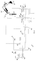
- the machine includes a system for operating the first, second and third hydraulic rams, as described below.
- Prime mover 41 may be an internal combustion engine, though other prime movers are suitable.
- a boom spool valve 44 can be operated by an operator manipulating boom control 46.
- boom control 46 is a joystick.
- a dipper spool 48 valve can be controlled via a dipper control 50.
- dipper control 50 is a joystick.
- Joystick 50 may be a separate joystick to joystick 46 (as shown in figure 2 ).
- the boom control 46 and dipper control 50 may be commonised within a single joystick.
- the material handling machine also includes a control system 52, the major components of which are valves V1, V2, V3, V4, V5, orifice O1 check valve C1 and associated hydraulic lines as will be further described below.
- Valve V1 is a hydraulically operated two position spool valve.
- Valve V2 is a hydraulic relief valve wherein the relief valve setting can be varied.
- Valve V3 is a two piston solenoid operated hydraulic spool valve.
- Valve V4 is a hydraulic compensator valve.
- Valve V5 is a two position solenoid operated hydraulic spool valve.
- the prime mover 41 drives the hydraulic pump 40 which takes hydraulic fluid from tank T and pressurises hydraulic line L1. As shown in figure 2 the dipper spool valve is closed and the boom spool valve is closed and hence pressurised fluid in line L1 will pass through the relief valve 51 back to tank T.
- the boom control 46 is operated such that the boom spool 44A of the boom spool valve 44 is moved so as to connect hydraulic line L1 and L2. This causes hydraulic fluid to pass into the head side pressure chamber of the first hydraulic ram thereby extending the hydraulic ram and raising the boom. Hydraulic fluid from the rod side chamber passes into hydraulic line L3 and back to tank T via the boom spool valve 44.
- the boom control 46 is operated to move the boom spool 44A in the opposite direction thereby connecting hydraulic line L1 with L3 and hydraulic line L2 with tank T.
- the dipper control 50 In order to move the dipper in a "dipper in” direction the dipper control 50 is operated such that the dipper spool 48A of the dipper spool valve 48 connects line L1 with hydraulic line L4. Hydraulic line L4 is connected to the head side of the hydraulic ram 34 which causes the ram to extend thereby pivoting the dipper arm in a clockwise direction about pivot 28. Hydraulic fluid in the rod side of hydraulic ram 34 passes into line L5 and then on through the dipper spool valve 48 to tank T. In order to move the dipper in a "dipper out” direction the dipper control 50 is operated such that the dipper spool connects line L1 with L5 and connects line L4 to tank. This results in retraction of the hydraulic ram 34 thereby causing the dipper to move in an anticlockwise direction about pivot 28.
- a bucket spool (not shown) and bucket control (not shown) operate in a similar manner to enable crowding or dumping of the bucket.
- a reaction force is provided by the hydraulic fluid in the head side chamber of the hydraulic ram 34.
- the hydraulic pressure in this chamber is indicative of a force of engagement between the bucket teeth 25 and the ground.
- a high pressure in the head side pressure chamber of hydraulic ram 34 indicates a high ground to tooth loading
- a low pressure in the head side pressure chamber of hydraulic ram 34 indicates a low ground to tooth force.
- a pressure in a hydraulic cylinder which is indicative of a force of engagement between the ground engaging implement such as a bucket and the ground can be used to control a further hydraulic ram or the like which in turn is operable to alter the force of engagement between the ground engaging implement and the ground.
- the control system 52 sets a target pressure for the pressure in the head side chamber of the hydraulic ram 34. If the target pressure is exceeded, then this is indicative of too great a force of engagement between the teeth 25 and the ground and the control system therefore lifts the boom thereby reducing the force of engagement between the teeth and the ground. Conversely if the pressure in the head side chamber of hydraulic ram 34 is below the target pressure then this is indicative of too small a force of engagement between the teeth and the ground and the control system causes the boom to be lowered, thereby increasing the force of engagement between the teeth and the ground. In this manner the control system controls the force of engagement between the teeth and the ground thereby ensuring efficient filling of the bucket and hence improving cycle times.
- the operator When the operator desires to use the control system 52, the operator sets the relief valve V2 to a desired relief valve blow off pressure setting (dependent upon the type of ground to be dug) and the button switch or other operator input device mentioned above is actuated thereby powering solenoid V31 and hence opening valve V3 as described above.
- the system is arranged such that as solenoid V31 is actuated, then simultaneously solenoid V51 is actuated thereby opening valve V5.
- the operator In order to start to dig a trench or the like the operator then manipulates the arm assembly 18 so that the teeth 25 are positioned remotely from the chassis and then engages the teeth 25 with the ground by further lowering the boom (as described above). The operator then manipulates the boom control 46, dipper control 50 and bucket control (not shown) so as to draw the teeth 25 generally towards the machine (as described above). Under these circumstances the teeth will be engaged with the ground and the dipper will be moving in a "dipper in" direction by a virtue of the fact that hydraulic ram 34 is being extended.
- valve V2 In the event that the boom is too low, the force of engagement between the teeth and the ground will increase as the dipper moves in the "dipper in” direction thereby increasing the pressure in the head side chamber of ram 34.
- This pressure is sensed by valve V2 by the virtue of pressure sensing line L6 and L7 being connected to line L8 which in turn is connected to line L4.
- valve V2 opens thereby causing a relatively small flow of hydraulic fluid through line L8, L7, L6 and V2 and back to tank T.
- orifice O1 creates a pressure drop between lines L7 and L6.
- the pressure in L7 will be greater than the pressure in L6.
- valve V5 is open and open valve V5 simply connects the rod side chamber of hydraulic ram 32 via line L13 to line L14 and hence to tank T.
- the rod side of the actuator 32 is always in a "float" condition, i.e. there is no restriction on hydraulic fluid entering or exiting the rod side hydraulic chamber.
- Check valve C1 is arranged to prevent back flow of hydraulic fluid from the head side chamber of hydraulic ram 32 into the head side chamber of hydraulic ram 34 in the event that the pressure in the head side hydraulic chamber of ram 32 exceeds the pressure in the head side hydraulic chamber of ram 34 when the spool V14 is arranged such that lines L8 and L9 are in fluid communication.
- control system 52 augments operation of the boom spool valve 44.
- the operator has full control of the boom spool valve 44, but hydraulic fluid flowing into or out of the head side/rod side chambers of hydraulic ram 32 is augmented by fluid flow along L1 and L13 under certain circumstances.
- FIG. 3 there is shown an alternative material handling machine 10' in which components that fulfil substantially the same function as those of material handling machine 10 are labelled similarly but with the addition of an '.
- a pressure sensor 60 provides a signal indicative of the pressure within the head side chamber of hydraulic ram 34'.
- the control system 52' includes a processor, in this case an ECU (electronic control unit).
- the control system 52' also includes a memory 62 within which can be stored a target pressure. An operator can modify the target pressure stored within the memory 62 dependent upon operating conditions, in particular ground conditions.
- the control system 52' can be enabled or disabled by the operator operating a button, switch or other operator input device (not shown).
- dipper spool valve 48' is solenoid operated, as is the boom spool valve 44'.
- the operator When the operator decides to use the control system 52' the operator sets the target pressure stored within memory 62 to desired level (dependent upon type of ground to be dug).
- the processor receives a signal from sensor 60 indicative of the pressure within the head side chamber of the hydraulic ram 34'.
- the processor compares this signal with the target pressure using comparator 63. In the event that the signal exceeds the target pressure the processor generates a signal indicative of a need to lift the boom.
- This signal is combined with a signal from the boom control 46' at a summing device 64 and a composite signal is then fed to the dipper spool valve 48' via signal line SL1.
- the signal received at the spool valve 48' will move the dipper spool 48A' differently than was instructed by the operator operating the boom control 46' and hence the boom will be raised by hydraulic ram 32'.
- the processor can be configured to receive a signal indicative of the pressure in the head side pressure chamber of hydraulic ram 34' and is configured to compare that signal with the target pressure, and in the event that the signal is less than the target pressure the processor is configured to generate a signal indicative of a need to lower the boom, the control system then operating hydraulic ram 32' in response to said signal to lower the boom to increase the force of engagement between the bucket teeth and the ground.
- the direction of movement of the bucket teeth is substantially horizontal. However, it may not be exactly horizontal, alternatively it could be angled upwardly as the teeth move towards the chassis or angled downwardly.
- the direction of movement of the ground engaging implement has a horizontal component of movement.
- the direction of movement may or may not include a vertical component of movement. Where the direction of movement includes a horizontal component of movement and a vertical component of movement the horizontal component of movement may be greater than the vertical component of movement.
- the target pressure may be varied at the discretion of the operator.
- the target pressure may be set relatively low.
- the target pressure may be set relatively high.
- control system may be enabled or disabled by operation of a button, switch or other operator input device.
- a control logic controlling enablement or disablement of the control system may require more than one event to enable/disable the system.
- the control system may only be enabled when both a button, switch or other operator input device has been operated by the operator and the pressure in the head side pressure chamber of hydraulic ram 34 or 34' is above a medium level. This minimum level may be indicative of the bucket starting to dig the ground. When the pressure is below this minimum level, this may be indicative of the bucket being disengaged from the ground, for example when the boom is being swung to the side so as to dump the material within the bucket.
- the control system may only be enabled when movement of the boom control 46, 46' and/or movement of the dipper control 50, 50' is above a certain level, for example the joystick has been moved passed a certain point.
- pressure in the second hydraulic ram 34 is compared with the target pressure.
- the pressure in the head side hydraulic chamber of the third hydraulic ram 36, 36' is also indicative of forced engagement between the ground engaging implement and the ground, and accordingly valve V2 could be connected to the head side chamber of hydraulic ram 36 or 36' or the pressure sensor 60 could be connected to the head side chamber of hydraulic ram 36 or 36'.
- the invention is not restricted to arm assemblies having a boom, dipper and ground engaging implement.
- the invention is applicable to other arm assemblies.
- the invention is applicable to the back hoe on a back hoe loading machine.
- a loader may have an arm pivotally mounted about a horizontal axis relative to the chassis of the back hoe loader.
- a shovel or other ground engaging implement may be mounted on the arm. In particular the shovel may be directly mounted on the arm, for example pivotally attached to the arm.
- a first hydraulic ram is operable to lift or lower the arm.
- a second hydraulic ram is operable to crowd or dump the shovel. The pressure within a pressure chamber of the ram that crowds or dumps the shovel will be indicative of a force of engagement between shovel and the ground, in particular where the machine is being driven forward and the teeth of the bucket are engaged with the ground and the bucket is therefore progressively being filled with ground material.
- the bucket may be "skimming" across the surface of the ground and not filling. Under these circumstances it is desirable to lower the arm to properly engage the bucket teeth with the ground. Alternatively, if the arm has been lowered too far, then the shovel teeth may be engagement with the ground to such an extent that the machine cannot be driven forward and hence the shovel will not be filled with ground material. Under these circumstances it is desirable to raise the arm thereby lifting the shovel teeth to enable the machine to be driven forward and hence fill the shovel with ground material.
- the invention is not restricted to ground engaging implements that collect ground material, such as shovels or buckets.
- the invention is equally applicable to other ground engaging implements, in particular a blade such as a bulldozer blade.
- the arm assembly 18 is pivotable laterally relative to the cab 14 and chassis 12. In further embodiments this need not be the case.
- the arm may be mounted directly to the chassis and cab 14 about a generally horizontal axis and the chassis and cab 14 may be able to rotate about a generally vertical axis relative to the ground engaging transport means.
Landscapes
- Engineering & Computer Science (AREA)
- Mining & Mineral Resources (AREA)
- Civil Engineering (AREA)
- General Engineering & Computer Science (AREA)
- Structural Engineering (AREA)
- Mechanical Engineering (AREA)
- Physics & Mathematics (AREA)
- Fluid Mechanics (AREA)
- Operation Control Of Excavators (AREA)
- Fluid-Pressure Circuits (AREA)
Claims (15)
- Materialhandhabungsmaschine (10), enthaltend:einen Arm (20, 22), der relativ zu einem Fahrgestell (12) der Maschine beweglich ist,ein erstes hydraulisches Stellglied (32; 32'), das funktioniert, den Arm relativ zum Fahrgestell anzuheben und abzusenken,ein in den Boden eingreifendes Arbeitsgerät (24; 24'), das am Arm montiert und relativ zum Arm beweglich ist,ein zweites hydraulisches Stellglied (34; 34'), das funktioniert, das in den Boden eingreifende Arbeitsgerät relativ zum Arm zu bewegen,dadurch gekennzeichnet, dass das zweite hydraulische Stellglied eine Druckkammer aufweist, wobei Druck in der Druckkammer eine Eingreifkraft zwischen dem in den Boden eingreifenden Arbeitsgerät und dem Boden anzeigt,ein Steuersystem (52; 52'), wobei das Steuersystem einen Zieldruck für die Druckkammer definiert, wobei das Steuersystem derart beschaffen ist, dass wenn ein Druck innerhalb der Druckkammer den Zieldruck übersteigt, das Steuersystem das erste hydraulische Stellglied antreibt, um den Arm anzuheben, um die Eingreifkraft zwischen dem in den Boden eingreifenden Arbeitsgerät und dem Boden zu verringern.
- Materialhandhabungsmaschine (10) nach Anspruch 1, wobei das Steuersystem (52; 52') derart beschaffen ist, dass wenn ein Druck innerhalb der Druckkammer geringer als der Zieldruck ist, das Steuersystem das erste hydraulische Stellglied (32; 32') antreibt, um den Arm (20, 22) abzusenken, um die Eingreifkraft zwischen dem in den Boden eingreifenden Arbeitsgerät (24; 24') und dem Boden zu erhöhen.
- Materialhandhabungsmaschine (10) nach Anspruch 1 oder 2, wobei das Steuersystem (52; 52') selektiv aktiviert und/oder selektiv deaktiviert werden kann.
- Materialhandhabungsmaschine (10) nach einem der vorherigen Ansprüche, wobei der Zieldruck selektiv veränderbar ist.
- Materialhandhabungsmaschine (10) nach einem der vorherigen Ansprüche, wobei das erste hydraulische Stellglied (32; 32') eine Druckkammer enthält, die funktioniert, um den Arm (20, 22) relativ zum Fahrgestell (12) anzuheben, wobei das Steuersystem (52; 52') derart beschaffen ist, dass wenn ein Druck innerhalb der Druckkammer des zweiten hydraulischen Stellglieds (34; 34') den Zieldruck überschreitet, etwas von dem Hydraulikfluidfluss hin zur Druckkammer des zweiten hydraulischen Stellglieds hin zur Druckkammer am ersten hydraulischen Stellglied abgeleitet wird, um den Arm anzuheben, wobei beispielsweise der hin zur Druckkammer des ersten hydraulischen Stellglieds abgeleitete Hydraulikfluss durch ein Einwegventil (C1) läuft, um einen Rückfluss zu verhindern.
- Materialhandhabungsmaschine (10) nach Anspruch 5, wobei der hin zur Druckkammer des ersten hydraulischen Stellglieds (32; 32') abgeleitete Hydraulikfluss durch ein Hydraulikventil (V1) läuft, das so funktioniert, dass der Hydraulikfluss in die und aus der Druckammer des ersten hydraulischen Stellglieds gesteuert wird, wobei das Hydraulikventil vorzugsweise ein Schieberventil ist.
- Materialhandhabungsmaschine (10) nach Anspruch 3, wobei das Steuersystem (52; 52') durch Betrieb eines Hydraulikventils (V3) selektiv aktiviert und/oder selektiv deaktiviert wird, wobei das vorzugsweise ein Schieberventil ist.
- Materialhandhabungsmaschine (10) nach Anspruch 4, wobei der Zieldruck durch ein Hydraulikdruckentlastungsventil (V2) definiert wird, vorzugsweise ein variables Hydraulikdruckentlastungsventil.
- Materialhandhabungsmaschine (10) nach einem der Ansprüche 1 bis 4, wobei das Steuersystem (52; 52') einen Prozessor enthält, wobei der Zieldruck vorzugsweise in einem Speicher gespeichert wird.
- Materialhandhabungsmaschine (10) nach Anspruch 9, wobei der Prozessor beschaffen ist, ein Signal aufzunehmen, das einen Druck in der Druckkammer anzeigt, und beschaffen ist, das Signal mit den Zieldruck zu vergleichen, und im Fall, dass das Signal den Zieldruck übersteigt, der Prozessor beschaffen ist, ein Signal zu erzeugen, das die Notwendigkeit anzeigt, den Arm (20, 22) zu heben, wobei das Steuersystem (52; 52') das erste hydraulische Stellglied (32; 32') in Erwiderung auf das Signal, den Arm anzuheben, antreibt, um die Eingreifkraft zwischen dem in den Boden eingreifenden Arbeitsgerät (24; 24') und dem Boden zu verringern.
- Materialhandhabungsmaschine (10) nach Anspruch 10, wobei der Prozessor beschaffen ist, ein Signal aufzunehmen, das einen Druck in der Druckkammer anzeigt, und beschaffen ist, das Signal mit den Zieldruck zu vergleichen, und im Fall, dass das Signal kleiner ist als der Zieldruck, der Prozessor beschaffen ist, ein Signal zu erzeugen, das die Notwendigkeit anzeigt, den Arm (20, 22) abzusenken, wobei das Steuersystem (52; 52') das erste hydraulische Stellglied (32; 32') in Erwiderung auf das Signal, den Arm abzusenken, antreibt, um die Eingreifkraft zwischen dem in den Boden eingreifenden Arbeitsgerät (24; 24') und dem Boden zu erhöhen.
- Materialhandhabungsmaschine (10) nach einem der vorherigen Ansprüche, wobei das in den Boden eingreifende Arbeitsgerät (24; 24') vorzugsweise schwenkbar direkt am Arm (20, 22) montiert ist.
- Materialhandhabungsmaschine (10) nach einem der vorherigen Ansprüche, wobei das zweite hydraulische Stellglied (34; 34') ein erstes Ende aufweist, das am Arm (20, 22) montiert ist.
- Materialhandhabungsmaschine (10) nach einem der Ansprüche 1 bis 11, wobei, wenn der Arm (20, 22) ein erster Arm (20) ist und das in den Boden eingreifende Arbeitsgerät (24; 24') an einem zweiten Arm (22) montiert ist, der zweite Arm am ersten Arm montiert ist, wobei der zweite Arm relativ zum ersten Arm beweglich ist.
- Materialhandhabungsmaschine (10) nach Anspruch 14, wobei das zweite hydraulische Stellglied (34; 34') ein erstes Ende aufweist, das am zweiten Arm (22) montiert ist.
Applications Claiming Priority (1)
| Application Number | Priority Date | Filing Date | Title |
|---|---|---|---|
| GB1410606.6A GB2530707A (en) | 2014-06-13 | 2014-06-13 | A material handling machine |
Publications (3)
| Publication Number | Publication Date |
|---|---|
| EP2955285A2 EP2955285A2 (de) | 2015-12-16 |
| EP2955285A3 EP2955285A3 (de) | 2016-01-13 |
| EP2955285B1 true EP2955285B1 (de) | 2017-12-13 |
Family
ID=51266583
Family Applications (1)
| Application Number | Title | Priority Date | Filing Date |
|---|---|---|---|
| EP15169229.0A Active EP2955285B1 (de) | 2014-06-13 | 2015-05-26 | Materialhandhabungsmaschine |
Country Status (5)
| Country | Link |
|---|---|
| US (1) | US9873999B2 (de) |
| EP (1) | EP2955285B1 (de) |
| JP (1) | JP2016006350A (de) |
| CN (1) | CN105178370B (de) |
| GB (1) | GB2530707A (de) |
Families Citing this family (1)
| Publication number | Priority date | Publication date | Assignee | Title |
|---|---|---|---|---|
| CN114701579A (zh) * | 2022-05-16 | 2022-07-05 | 河北农业大学 | 一种履带式行走装置 |
Family Cites Families (14)
| Publication number | Priority date | Publication date | Assignee | Title |
|---|---|---|---|---|
| EP0411151B1 (de) * | 1989-02-20 | 1994-07-06 | Hitachi Construction Machinery Co., Ltd. | Hydraulische schaltung für maschinen |
| JP3528981B2 (ja) * | 1994-08-30 | 2004-05-24 | 株式会社小松製作所 | 油圧ショベルのブームシリンダ用油圧回路 |
| US6955115B1 (en) * | 1999-03-17 | 2005-10-18 | Caterpillar Inc. | Hydraulic circuit having pressure equalization during regeneration |
| DE19939796C1 (de) * | 1999-08-21 | 2000-11-23 | Orenstein & Koppel Ag | Verfahren und Arbeitsmaschine zur Herstellung von Bodenflächen |
| JP3902168B2 (ja) * | 2003-09-04 | 2007-04-04 | 日立建機株式会社 | 建設機械の診断情報表示システム |
| GB0409086D0 (en) * | 2004-04-23 | 2004-05-26 | King S College London | Improvements in or relating to digging apparatus and methods |
| JP2006183413A (ja) * | 2004-12-28 | 2006-07-13 | Shin Caterpillar Mitsubishi Ltd | 建設機械の制御回路 |
| US7905089B2 (en) * | 2007-09-13 | 2011-03-15 | Caterpillar Inc. | Actuator control system implementing adaptive flow control |
| WO2009075613A1 (en) * | 2007-12-12 | 2009-06-18 | Volvo Construction Equipment Ab | A method for when necessary automatically limiting a pressure in a hydrualic system during operation |
| US8095281B2 (en) * | 2008-12-11 | 2012-01-10 | Caterpillar Inc. | System for controlling a hydraulic system |
| CA2776152C (en) * | 2009-09-29 | 2014-11-18 | Purdue Research Foundation | Regenerative hydraulic systems and methods of use |
| US9169620B2 (en) * | 2011-11-22 | 2015-10-27 | Caterpillar Inc. | Work implement control system |
| JP6003229B2 (ja) * | 2012-05-24 | 2016-10-05 | コベルコ建機株式会社 | 建設機械のブーム駆動装置 |
| WO2014068973A1 (ja) * | 2012-10-30 | 2014-05-08 | 川崎重工業株式会社 | 液圧制御装置 |
-
2014
- 2014-06-13 GB GB1410606.6A patent/GB2530707A/en not_active Withdrawn
-
2015
- 2015-05-26 EP EP15169229.0A patent/EP2955285B1/de active Active
- 2015-06-11 US US14/737,319 patent/US9873999B2/en active Active
- 2015-06-12 JP JP2015118801A patent/JP2016006350A/ja active Pending
- 2015-06-15 CN CN201510329458.6A patent/CN105178370B/zh active Active
Non-Patent Citations (1)
| Title |
|---|
| None * |
Also Published As
| Publication number | Publication date |
|---|---|
| GB2530707A (en) | 2016-04-06 |
| JP2016006350A (ja) | 2016-01-14 |
| US9873999B2 (en) | 2018-01-23 |
| CN105178370A (zh) | 2015-12-23 |
| EP2955285A3 (de) | 2016-01-13 |
| CN105178370B (zh) | 2019-05-17 |
| GB201410606D0 (en) | 2014-07-30 |
| EP2955285A2 (de) | 2015-12-16 |
| US20150361637A1 (en) | 2015-12-17 |
Similar Documents
| Publication | Publication Date | Title |
|---|---|---|
| JP7186504B2 (ja) | ショベル | |
| US10246855B2 (en) | Material handling machine with bucket shake control system and method | |
| US11118327B2 (en) | Work machine | |
| EP3000944B1 (de) | Materialhandhabungsmaschine | |
| US8800278B2 (en) | Hydraulic drive device for hydraulic excavator | |
| US9051944B2 (en) | Hydraulic system and control logic for collection and recovery of energy in a double actuator arrangement | |
| US4776751A (en) | Crowd control system for a loader | |
| CN104053912A (zh) | 作业工具控制系统 | |
| CN110382785A (zh) | 作业机械 | |
| US7434394B2 (en) | Hydraulic drive device | |
| EP2955285B1 (de) | Materialhandhabungsmaschine | |
| EP1635001A2 (de) | Baumaschine | |
| JP7609353B2 (ja) | ショベル | |
| JP6781181B2 (ja) | 伸縮アームを有する作業機械 | |
| CN114423907A (zh) | 工程机械 | |
| GB2527598A (en) | A material handling machine | |
| JPH0654025B2 (ja) | シヨベルの油圧回路 | |
| KR101936329B1 (ko) | 건설장비 | |
| WO2025205250A1 (ja) | 深礎掘削機 | |
| JPH0250257B2 (de) |
Legal Events
| Date | Code | Title | Description |
|---|---|---|---|
| PUAL | Search report despatched |
Free format text: ORIGINAL CODE: 0009013 |
|
| PUAI | Public reference made under article 153(3) epc to a published international application that has entered the european phase |
Free format text: ORIGINAL CODE: 0009012 |
|
| AK | Designated contracting states |
Kind code of ref document: A2 Designated state(s): AL AT BE BG CH CY CZ DE DK EE ES FI FR GB GR HR HU IE IS IT LI LT LU LV MC MK MT NL NO PL PT RO RS SE SI SK SM TR |
|
| AX | Request for extension of the european patent |
Extension state: BA ME |
|
| AK | Designated contracting states |
Kind code of ref document: A3 Designated state(s): AL AT BE BG CH CY CZ DE DK EE ES FI FR GB GR HR HU IE IS IT LI LT LU LV MC MK MT NL NO PL PT RO RS SE SI SK SM TR |
|
| AX | Request for extension of the european patent |
Extension state: BA ME |
|
| RIC1 | Information provided on ipc code assigned before grant |
Ipc: E02F 9/22 20060101AFI20151208BHEP |
|
| 17P | Request for examination filed |
Effective date: 20160713 |
|
| RBV | Designated contracting states (corrected) |
Designated state(s): AL AT BE BG CH CY CZ DE DK EE ES FI FR GB GR HR HU IE IS IT LI LT LU LV MC MK MT NL NO PL PT RO RS SE SI SK SM TR |
|
| GRAP | Despatch of communication of intention to grant a patent |
Free format text: ORIGINAL CODE: EPIDOSNIGR1 |
|
| STAA | Information on the status of an ep patent application or granted ep patent |
Free format text: STATUS: GRANT OF PATENT IS INTENDED |
|
| INTG | Intention to grant announced |
Effective date: 20170628 |
|
| GRAS | Grant fee paid |
Free format text: ORIGINAL CODE: EPIDOSNIGR3 |
|
| GRAA | (expected) grant |
Free format text: ORIGINAL CODE: 0009210 |
|
| STAA | Information on the status of an ep patent application or granted ep patent |
Free format text: STATUS: THE PATENT HAS BEEN GRANTED |
|
| REG | Reference to a national code |
Ref country code: GB Ref legal event code: FG4D |
|
| REG | Reference to a national code |
Ref country code: AT Ref legal event code: REF Ref document number: 954496 Country of ref document: AT Kind code of ref document: T Effective date: 20171215 Ref country code: CH Ref legal event code: EP |
|
| REG | Reference to a national code |
Ref country code: IE Ref legal event code: FG4D |
|
| REG | Reference to a national code |
Ref country code: DE Ref legal event code: R096 Ref document number: 602015006574 Country of ref document: DE |
|
| REG | Reference to a national code |
Ref country code: NL Ref legal event code: MP Effective date: 20171213 |
|
| PG25 | Lapsed in a contracting state [announced via postgrant information from national office to epo] |
Ref country code: SE Free format text: LAPSE BECAUSE OF FAILURE TO SUBMIT A TRANSLATION OF THE DESCRIPTION OR TO PAY THE FEE WITHIN THE PRESCRIBED TIME-LIMIT Effective date: 20171213 Ref country code: FI Free format text: LAPSE BECAUSE OF FAILURE TO SUBMIT A TRANSLATION OF THE DESCRIPTION OR TO PAY THE FEE WITHIN THE PRESCRIBED TIME-LIMIT Effective date: 20171213 Ref country code: NO Free format text: LAPSE BECAUSE OF FAILURE TO SUBMIT A TRANSLATION OF THE DESCRIPTION OR TO PAY THE FEE WITHIN THE PRESCRIBED TIME-LIMIT Effective date: 20180313 |
|
| REG | Reference to a national code |
Ref country code: AT Ref legal event code: MK05 Ref document number: 954496 Country of ref document: AT Kind code of ref document: T Effective date: 20171213 |
|
| REG | Reference to a national code |
Ref country code: FR Ref legal event code: PLFP Year of fee payment: 4 |
|
| PG25 | Lapsed in a contracting state [announced via postgrant information from national office to epo] |
Ref country code: LV Free format text: LAPSE BECAUSE OF FAILURE TO SUBMIT A TRANSLATION OF THE DESCRIPTION OR TO PAY THE FEE WITHIN THE PRESCRIBED TIME-LIMIT Effective date: 20171213 Ref country code: HR Free format text: LAPSE BECAUSE OF FAILURE TO SUBMIT A TRANSLATION OF THE DESCRIPTION OR TO PAY THE FEE WITHIN THE PRESCRIBED TIME-LIMIT Effective date: 20171213 Ref country code: RS Free format text: LAPSE BECAUSE OF FAILURE TO SUBMIT A TRANSLATION OF THE DESCRIPTION OR TO PAY THE FEE WITHIN THE PRESCRIBED TIME-LIMIT Effective date: 20171213 Ref country code: GR Free format text: LAPSE BECAUSE OF FAILURE TO SUBMIT A TRANSLATION OF THE DESCRIPTION OR TO PAY THE FEE WITHIN THE PRESCRIBED TIME-LIMIT Effective date: 20180314 Ref country code: BG Free format text: LAPSE BECAUSE OF FAILURE TO SUBMIT A TRANSLATION OF THE DESCRIPTION OR TO PAY THE FEE WITHIN THE PRESCRIBED TIME-LIMIT Effective date: 20180313 |
|
| PG25 | Lapsed in a contracting state [announced via postgrant information from national office to epo] |
Ref country code: NL Free format text: LAPSE BECAUSE OF FAILURE TO SUBMIT A TRANSLATION OF THE DESCRIPTION OR TO PAY THE FEE WITHIN THE PRESCRIBED TIME-LIMIT Effective date: 20171213 |
|
| PG25 | Lapsed in a contracting state [announced via postgrant information from national office to epo] |
Ref country code: CZ Free format text: LAPSE BECAUSE OF FAILURE TO SUBMIT A TRANSLATION OF THE DESCRIPTION OR TO PAY THE FEE WITHIN THE PRESCRIBED TIME-LIMIT Effective date: 20171213 Ref country code: SK Free format text: LAPSE BECAUSE OF FAILURE TO SUBMIT A TRANSLATION OF THE DESCRIPTION OR TO PAY THE FEE WITHIN THE PRESCRIBED TIME-LIMIT Effective date: 20171213 Ref country code: ES Free format text: LAPSE BECAUSE OF FAILURE TO SUBMIT A TRANSLATION OF THE DESCRIPTION OR TO PAY THE FEE WITHIN THE PRESCRIBED TIME-LIMIT Effective date: 20171213 Ref country code: CY Free format text: LAPSE BECAUSE OF FAILURE TO SUBMIT A TRANSLATION OF THE DESCRIPTION OR TO PAY THE FEE WITHIN THE PRESCRIBED TIME-LIMIT Effective date: 20171213 Ref country code: EE Free format text: LAPSE BECAUSE OF FAILURE TO SUBMIT A TRANSLATION OF THE DESCRIPTION OR TO PAY THE FEE WITHIN THE PRESCRIBED TIME-LIMIT Effective date: 20171213 |
|
| PG25 | Lapsed in a contracting state [announced via postgrant information from national office to epo] |
Ref country code: IS Free format text: LAPSE BECAUSE OF FAILURE TO SUBMIT A TRANSLATION OF THE DESCRIPTION OR TO PAY THE FEE WITHIN THE PRESCRIBED TIME-LIMIT Effective date: 20180413 Ref country code: RO Free format text: LAPSE BECAUSE OF FAILURE TO SUBMIT A TRANSLATION OF THE DESCRIPTION OR TO PAY THE FEE WITHIN THE PRESCRIBED TIME-LIMIT Effective date: 20171213 Ref country code: PL Free format text: LAPSE BECAUSE OF FAILURE TO SUBMIT A TRANSLATION OF THE DESCRIPTION OR TO PAY THE FEE WITHIN THE PRESCRIBED TIME-LIMIT Effective date: 20171213 Ref country code: SM Free format text: LAPSE BECAUSE OF FAILURE TO SUBMIT A TRANSLATION OF THE DESCRIPTION OR TO PAY THE FEE WITHIN THE PRESCRIBED TIME-LIMIT Effective date: 20171213 Ref country code: AT Free format text: LAPSE BECAUSE OF FAILURE TO SUBMIT A TRANSLATION OF THE DESCRIPTION OR TO PAY THE FEE WITHIN THE PRESCRIBED TIME-LIMIT Effective date: 20171213 |
|
| REG | Reference to a national code |
Ref country code: DE Ref legal event code: R097 Ref document number: 602015006574 Country of ref document: DE |
|
| PLBE | No opposition filed within time limit |
Free format text: ORIGINAL CODE: 0009261 |
|
| STAA | Information on the status of an ep patent application or granted ep patent |
Free format text: STATUS: NO OPPOSITION FILED WITHIN TIME LIMIT |
|
| 26N | No opposition filed |
Effective date: 20180914 |
|
| PG25 | Lapsed in a contracting state [announced via postgrant information from national office to epo] |
Ref country code: DK Free format text: LAPSE BECAUSE OF FAILURE TO SUBMIT A TRANSLATION OF THE DESCRIPTION OR TO PAY THE FEE WITHIN THE PRESCRIBED TIME-LIMIT Effective date: 20171213 |
|
| REG | Reference to a national code |
Ref country code: CH Ref legal event code: PL |
|
| REG | Reference to a national code |
Ref country code: BE Ref legal event code: MM Effective date: 20180531 |
|
| PG25 | Lapsed in a contracting state [announced via postgrant information from national office to epo] |
Ref country code: MC Free format text: LAPSE BECAUSE OF FAILURE TO SUBMIT A TRANSLATION OF THE DESCRIPTION OR TO PAY THE FEE WITHIN THE PRESCRIBED TIME-LIMIT Effective date: 20171213 |
|
| REG | Reference to a national code |
Ref country code: IE Ref legal event code: MM4A |
|
| PG25 | Lapsed in a contracting state [announced via postgrant information from national office to epo] |
Ref country code: LI Free format text: LAPSE BECAUSE OF NON-PAYMENT OF DUE FEES Effective date: 20180531 Ref country code: CH Free format text: LAPSE BECAUSE OF NON-PAYMENT OF DUE FEES Effective date: 20180531 Ref country code: SI Free format text: LAPSE BECAUSE OF FAILURE TO SUBMIT A TRANSLATION OF THE DESCRIPTION OR TO PAY THE FEE WITHIN THE PRESCRIBED TIME-LIMIT Effective date: 20171213 |
|
| PG25 | Lapsed in a contracting state [announced via postgrant information from national office to epo] |
Ref country code: LU Free format text: LAPSE BECAUSE OF NON-PAYMENT OF DUE FEES Effective date: 20180526 |
|
| PG25 | Lapsed in a contracting state [announced via postgrant information from national office to epo] |
Ref country code: IE Free format text: LAPSE BECAUSE OF NON-PAYMENT OF DUE FEES Effective date: 20180526 |
|
| PG25 | Lapsed in a contracting state [announced via postgrant information from national office to epo] |
Ref country code: BE Free format text: LAPSE BECAUSE OF NON-PAYMENT OF DUE FEES Effective date: 20180531 |
|
| PG25 | Lapsed in a contracting state [announced via postgrant information from national office to epo] |
Ref country code: MT Free format text: LAPSE BECAUSE OF NON-PAYMENT OF DUE FEES Effective date: 20180526 |
|
| PG25 | Lapsed in a contracting state [announced via postgrant information from national office to epo] |
Ref country code: TR Free format text: LAPSE BECAUSE OF FAILURE TO SUBMIT A TRANSLATION OF THE DESCRIPTION OR TO PAY THE FEE WITHIN THE PRESCRIBED TIME-LIMIT Effective date: 20171213 |
|
| PG25 | Lapsed in a contracting state [announced via postgrant information from national office to epo] |
Ref country code: PT Free format text: LAPSE BECAUSE OF FAILURE TO SUBMIT A TRANSLATION OF THE DESCRIPTION OR TO PAY THE FEE WITHIN THE PRESCRIBED TIME-LIMIT Effective date: 20171213 |
|
| PG25 | Lapsed in a contracting state [announced via postgrant information from national office to epo] |
Ref country code: MK Free format text: LAPSE BECAUSE OF NON-PAYMENT OF DUE FEES Effective date: 20171213 Ref country code: LT Free format text: LAPSE BECAUSE OF FAILURE TO SUBMIT A TRANSLATION OF THE DESCRIPTION OR TO PAY THE FEE WITHIN THE PRESCRIBED TIME-LIMIT Effective date: 20171213 Ref country code: HU Free format text: LAPSE BECAUSE OF FAILURE TO SUBMIT A TRANSLATION OF THE DESCRIPTION OR TO PAY THE FEE WITHIN THE PRESCRIBED TIME-LIMIT; INVALID AB INITIO Effective date: 20150526 |
|
| PG25 | Lapsed in a contracting state [announced via postgrant information from national office to epo] |
Ref country code: AL Free format text: LAPSE BECAUSE OF FAILURE TO SUBMIT A TRANSLATION OF THE DESCRIPTION OR TO PAY THE FEE WITHIN THE PRESCRIBED TIME-LIMIT Effective date: 20171213 |
|
| PLAA | Information modified related to event that no opposition was filed |
Free format text: ORIGINAL CODE: 0009299DELT |
|
| PLBE | No opposition filed within time limit |
Free format text: ORIGINAL CODE: 0009261 |
|
| R26N | No opposition filed (corrected) |
Effective date: 20180914 |
|
| 26N | No opposition filed |
Effective date: 20180914 |
|
| REG | Reference to a national code |
Ref country code: GB Ref legal event code: 746 Effective date: 20230123 |
|
| P01 | Opt-out of the competence of the unified patent court (upc) registered |
Effective date: 20230525 |
|
| PGFP | Annual fee paid to national office [announced via postgrant information from national office to epo] |
Ref country code: DE Payment date: 20250521 Year of fee payment: 11 |
|
| PGFP | Annual fee paid to national office [announced via postgrant information from national office to epo] |
Ref country code: IT Payment date: 20250523 Year of fee payment: 11 |
|
| PGFP | Annual fee paid to national office [announced via postgrant information from national office to epo] |
Ref country code: FR Payment date: 20250528 Year of fee payment: 11 |
|
| PGFP | Annual fee paid to national office [announced via postgrant information from national office to epo] |
Ref country code: GB Payment date: 20260323 Year of fee payment: 12 |