EP2955359A2 - Système inverseur de poussée de turboréacteur - Google Patents
Système inverseur de poussée de turboréacteur Download PDFInfo
- Publication number
- EP2955359A2 EP2955359A2 EP15168995.7A EP15168995A EP2955359A2 EP 2955359 A2 EP2955359 A2 EP 2955359A2 EP 15168995 A EP15168995 A EP 15168995A EP 2955359 A2 EP2955359 A2 EP 2955359A2
- Authority
- EP
- European Patent Office
- Prior art keywords
- clutch
- fan
- gear system
- spline
- engine
- Prior art date
- Legal status (The legal status is an assumption and is not a legal conclusion. Google has not performed a legal analysis and makes no representation as to the accuracy of the status listed.)
- Granted
Links
Images




Classifications
-
- F—MECHANICAL ENGINEERING; LIGHTING; HEATING; WEAPONS; BLASTING
- F02—COMBUSTION ENGINES; HOT-GAS OR COMBUSTION-PRODUCT ENGINE PLANTS
- F02K—JET-PROPULSION PLANTS
- F02K1/00—Plants characterised by the form or arrangement of the jet pipe or nozzle; Jet pipes or nozzles peculiar thereto
- F02K1/54—Nozzles having means for reversing jet thrust
- F02K1/64—Reversing fan flow
- F02K1/70—Reversing fan flow using thrust reverser flaps or doors mounted on the fan housing
-
- F—MECHANICAL ENGINEERING; LIGHTING; HEATING; WEAPONS; BLASTING
- F02—COMBUSTION ENGINES; HOT-GAS OR COMBUSTION-PRODUCT ENGINE PLANTS
- F02C—GAS-TURBINE PLANTS; AIR INTAKES FOR JET-PROPULSION PLANTS; CONTROLLING FUEL SUPPLY IN AIR-BREATHING JET-PROPULSION PLANTS
- F02C3/00—Gas-turbine plants characterised by the use of combustion products as the working fluid
- F02C3/04—Gas-turbine plants characterised by the use of combustion products as the working fluid having a turbine driving a compressor
- F02C3/10—Gas-turbine plants characterised by the use of combustion products as the working fluid having a turbine driving a compressor with another turbine driving an output shaft but not driving the compressor
-
- F—MECHANICAL ENGINEERING; LIGHTING; HEATING; WEAPONS; BLASTING
- F02—COMBUSTION ENGINES; HOT-GAS OR COMBUSTION-PRODUCT ENGINE PLANTS
- F02C—GAS-TURBINE PLANTS; AIR INTAKES FOR JET-PROPULSION PLANTS; CONTROLLING FUEL SUPPLY IN AIR-BREATHING JET-PROPULSION PLANTS
- F02C3/00—Gas-turbine plants characterised by the use of combustion products as the working fluid
- F02C3/04—Gas-turbine plants characterised by the use of combustion products as the working fluid having a turbine driving a compressor
- F02C3/107—Gas-turbine plants characterised by the use of combustion products as the working fluid having a turbine driving a compressor with two or more rotors connected by power transmission
- F02C3/113—Gas-turbine plants characterised by the use of combustion products as the working fluid having a turbine driving a compressor with two or more rotors connected by power transmission with variable power transmission between rotors
-
- F—MECHANICAL ENGINEERING; LIGHTING; HEATING; WEAPONS; BLASTING
- F02—COMBUSTION ENGINES; HOT-GAS OR COMBUSTION-PRODUCT ENGINE PLANTS
- F02C—GAS-TURBINE PLANTS; AIR INTAKES FOR JET-PROPULSION PLANTS; CONTROLLING FUEL SUPPLY IN AIR-BREATHING JET-PROPULSION PLANTS
- F02C3/00—Gas-turbine plants characterised by the use of combustion products as the working fluid
- F02C3/14—Gas-turbine plants characterised by the use of combustion products as the working fluid characterised by the arrangement of the combustion chamber in the plant
- F02C3/145—Gas-turbine plants characterised by the use of combustion products as the working fluid characterised by the arrangement of the combustion chamber in the plant the combustion chamber being in the reverse flow-type
-
- F—MECHANICAL ENGINEERING; LIGHTING; HEATING; WEAPONS; BLASTING
- F02—COMBUSTION ENGINES; HOT-GAS OR COMBUSTION-PRODUCT ENGINE PLANTS
- F02C—GAS-TURBINE PLANTS; AIR INTAKES FOR JET-PROPULSION PLANTS; CONTROLLING FUEL SUPPLY IN AIR-BREATHING JET-PROPULSION PLANTS
- F02C6/00—Plural gas-turbine plants; Combinations of gas-turbine plants with other apparatus; Adaptations of gas-turbine plants for special use
- F02C6/04—Gas-turbine plants providing heated or pressurised working fluid for other apparatus, e.g. without mechanical power output
-
- F—MECHANICAL ENGINEERING; LIGHTING; HEATING; WEAPONS; BLASTING
- F02—COMBUSTION ENGINES; HOT-GAS OR COMBUSTION-PRODUCT ENGINE PLANTS
- F02C—GAS-TURBINE PLANTS; AIR INTAKES FOR JET-PROPULSION PLANTS; CONTROLLING FUEL SUPPLY IN AIR-BREATHING JET-PROPULSION PLANTS
- F02C7/00—Features, components parts, details or accessories, not provided for in, or of interest apart form groups F02C1/00 - F02C6/00; Air intakes for jet-propulsion plants
- F02C7/36—Power transmission arrangements between the different shafts of the gas turbine plant, or between the gas-turbine plant and the power user
-
- F—MECHANICAL ENGINEERING; LIGHTING; HEATING; WEAPONS; BLASTING
- F02—COMBUSTION ENGINES; HOT-GAS OR COMBUSTION-PRODUCT ENGINE PLANTS
- F02K—JET-PROPULSION PLANTS
- F02K1/00—Plants characterised by the form or arrangement of the jet pipe or nozzle; Jet pipes or nozzles peculiar thereto
- F02K1/28—Plants characterised by the form or arrangement of the jet pipe or nozzle; Jet pipes or nozzles peculiar thereto using fluid jets to influence the jet flow
- F02K1/32—Plants characterised by the form or arrangement of the jet pipe or nozzle; Jet pipes or nozzles peculiar thereto using fluid jets to influence the jet flow for reversing thrust
-
- F—MECHANICAL ENGINEERING; LIGHTING; HEATING; WEAPONS; BLASTING
- F02—COMBUSTION ENGINES; HOT-GAS OR COMBUSTION-PRODUCT ENGINE PLANTS
- F02K—JET-PROPULSION PLANTS
- F02K3/00—Plants including a gas turbine driving a compressor or a ducted fan
- F02K3/02—Plants including a gas turbine driving a compressor or a ducted fan in which part of the working fluid by-passes the turbine and combustion chamber
- F02K3/04—Plants including a gas turbine driving a compressor or a ducted fan in which part of the working fluid by-passes the turbine and combustion chamber the plant including ducted fans, i.e. fans with high volume, low pressure outputs, for augmenting the jet thrust, e.g. of double-flow type
- F02K3/075—Plants including a gas turbine driving a compressor or a ducted fan in which part of the working fluid by-passes the turbine and combustion chamber the plant including ducted fans, i.e. fans with high volume, low pressure outputs, for augmenting the jet thrust, e.g. of double-flow type controlling flow ratio between flows
-
- F—MECHANICAL ENGINEERING; LIGHTING; HEATING; WEAPONS; BLASTING
- F16—ENGINEERING ELEMENTS AND UNITS; GENERAL MEASURES FOR PRODUCING AND MAINTAINING EFFECTIVE FUNCTIONING OF MACHINES OR INSTALLATIONS; THERMAL INSULATION IN GENERAL
- F16H—GEARING
- F16H3/00—Toothed gearings for conveying rotary motion with variable gear ratio or for reversing rotary motion
- F16H3/44—Toothed gearings for conveying rotary motion with variable gear ratio or for reversing rotary motion using gears having orbital motion
- F16H3/46—Gearings having only two central gears, connected by orbital gears
- F16H3/60—Gearings for reversal only
-
- F—MECHANICAL ENGINEERING; LIGHTING; HEATING; WEAPONS; BLASTING
- F05—INDEXING SCHEMES RELATING TO ENGINES OR PUMPS IN VARIOUS SUBCLASSES OF CLASSES F01-F04
- F05D—INDEXING SCHEME FOR ASPECTS RELATING TO NON-POSITIVE-DISPLACEMENT MACHINES OR ENGINES, GAS-TURBINES OR JET-PROPULSION PLANTS
- F05D2260/00—Function
- F05D2260/40—Transmission of power
- F05D2260/403—Transmission of power through the shape of the drive components
- F05D2260/4031—Transmission of power through the shape of the drive components as in toothed gearing
- F05D2260/40311—Transmission of power through the shape of the drive components as in toothed gearing of the epicyclical, planetary or differential type
-
- Y—GENERAL TAGGING OF NEW TECHNOLOGICAL DEVELOPMENTS; GENERAL TAGGING OF CROSS-SECTIONAL TECHNOLOGIES SPANNING OVER SEVERAL SECTIONS OF THE IPC; TECHNICAL SUBJECTS COVERED BY FORMER USPC CROSS-REFERENCE ART COLLECTIONS [XRACs] AND DIGESTS
- Y02—TECHNOLOGIES OR APPLICATIONS FOR MITIGATION OR ADAPTATION AGAINST CLIMATE CHANGE
- Y02T—CLIMATE CHANGE MITIGATION TECHNOLOGIES RELATED TO TRANSPORTATION
- Y02T50/00—Aeronautics or air transport
- Y02T50/60—Efficient propulsion technologies, e.g. for aircraft
Definitions
- the present disclosure is directed generally to thrust reversers for gas turbine engines. More specifically, the present disclosure is directed to systems for producing reverse thrust using a bypass turbofan.
- Typical large bypass ratio turbofan engines utilize thrust reversers to assist aircraft in reducing speed during landing operations.
- Conventional thrust reverses involve interrupting the flow of bypass air generated by the turbofan with a blocker door, and rerouting the flow of that air in a forward direction to counteract forward speed of the aircraft.
- blocker door thrust reversal system is described in U.S. Pat. No. 8,109,467 , which is assigned to United Technologies Corporation. Blocker door systems, however, can add upwards of 1,000 pounds ( ⁇ 453.6 kg) of weight to the aircraft.
- Other attempts of reversing the direction of airflow generated by the fan have involved reversing the rotation of the fan itself using a clutch.
- One such clutch thrust reversal system is described in U.S. Pat. No.
- a gas turbine engine comprises a core engine, a fan, a bypass duct and a clutch.
- the fan is driven by the core engine.
- the bypass duct is configured to receive airflow from the fan.
- the clutch links the core engine and the fan.
- the core comprises a reverse-flow, two-spool gas generator in one embodiment.
- the fan is driven by a free turbine aerodynamically powered by the core engine.
- the clutch includes reverse gearing to reverse rotational output of the fan.
- the clutch and reverse gearing are implemented in an epicyclic gear system.
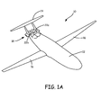
- aircraft 10 includes fuselage 12 having wings 16 and tail 14.
- Propulsion system 18 is mounted aft end of fuselage 12.
- Propulsion system 18 includes first and second engine cores 20a - 20b, which are reverse core gas turbine engines, that drive corresponding first and second propulsors, that include respective fan sections 22a - 22b.
- First and second fan sections 22a - 22b provide the propulsive thrust of the disclosed propulsion system.
- Each of fan sections 22a - 22b are disposed about corresponding first and second propulsor axis A1 and A2.
- First and second engine cores 20a - 20b are disposed about corresponding first and second engine axes B1 and B2.
- First engine core 20a is disposed about first engine axis B1 and drives the first propulsor about first propulsor axis A1.
- Second engine core 20b is disposed about second engine axis B2 and drives second fan section 20b about second propulsor axis A2.
- the illustrated reverse engine cores 20a - 20b are gas generators that include compressor 24, combustor 26 and turbine 28. Air is drawn in through inlets 32a - 32b to compressor 24 and is compressed and communicated to combustor 26. In combustor 26, air is mixed with fuel and ignited to generate an exhaust gas stream that expands through turbine 28 where energy is extracted and utilized to drive compressor 24 and corresponding fan 22a - 22b.
- engine cores 20a - 20b drive corresponding fan 22a - 22b through geared architecture 30a - 30b, which is also considered part of the respective propulsor.
- each of first and second fans 22a - 22b and related gearing 30a - 30b is mounted substantially parallel to each other about respective propulsor axes A1, A2.
- First and second engine axes B1, B2 are disposed at angle 34 relative to corresponding propulsor axis A1, A2.
- angle 34 is greater than about thirty (30) degrees. As appreciated other angles are within the contemplation of this disclosure.
- gas turbine engines are not typically mounted next to each other due to practical limitations related to overall aircraft survivability in the event of engine failure.
- a burst zone is defined between gas turbine engines within which another gas turbine engine is not permitted due to possible fragmentation from one failed engine disabling the second engine.
- Engine cores 20a - 20b are disposed at angle 34 relative to the corresponding propulsor axes A1 and A2 and to each other such that neither engine core 20a - 20b is disposed within burst zone 36a - 36b of the other engine core 20a - 20b.
- each of engine cores 20a - 20b is disposed at an angle away from the other engine core 20a - 20b such that each is orientated outside of the other's burst zone 36a - 36b.
- engine cores 20a - 20b are angled away from each other at angle 42 ( FIG. 1B ).
- angle 42 is greater than about ninety (90) degrees.
- other angles 42 could be utilized depending on the definition of respective burst zones 36a - 36b.
- the respective burst zones 36a - 36b are defined as respective annular regions about corresponding engine core 20a - 20b.
- the annular region is disposed at angle 38 outward from line 40 perpendicular to engine axis B1, B2.
- the example angle is at least fifteen (15) degrees and is determined based on application specific considerations.
- airframe regulations may also define an angular span of burst zones 36a - 36b and thereby angle 38.
- first and second engine cores 20a - 20b defines the corresponding burst zones 36a - 36b that does not interfere with the other engine core 20a - 20b to comply with application specific survivability requirements.
- gas generators are mounted in a configuration placing each outside of the other's burst zone, fuselage and substantially adjacent mounted propulsors are feasible within desired limitations.
- the side by side adjacent mounting configuration further enables alternate aircraft architectures.
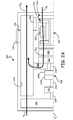
- FIG. 2A is a schematic view of turbofan engine 210 comprising two-spool, reverse flow core 212, and clutch 214 coupling fan 216 and free turbine 218.
- Core 212 includes combustor 220, high pressure spool 222 and low pressure spool 224.
- Transition duct 226 fluidly couples core 212 with free turbine 218.
- Vent duct 228 fluidly couples to free turbine 218 and bypass duct 230.
- Free turbine 218 mechanically drives clutch 214 via drive shaft 232.
- Clutch 214 is schematically shown as a friction clutch having disks 214A and 214B, although other types of clutches may be used.
- Clutch 214 drives gear system 234 through flex coupling 236, and gear system 234 provides input to fan 216 through fan shaft 238.
- Bypass duct 230 includes thrust reverser 239, which comprises blocker door 240, vent 242 and cowl 244.
- Turbofan engine 210 is concentrically disposed about engine centerline CL.
- inlet air A I passes through core 212 and is converted to combustion gases A CG .
- Ambient air A A enters bypass duct 230 and is driven by fan 216 to exit bypass duct as bypass air A B .
- Core 212 is disposed in a case structure wherein inlet air A I is drawn in at the aft end of core 212 and pushed forward to transition duct 226 at the forward end.
- core 212 may be fed with bypass air A B via a diffuser duct connecting core 212 to bypass duct 230 at the aft end of turbofan engine 210.
- Core 212 operates using known Brayton cycle principles to convert ambient air A A into combustion gases A CG .
- combustor 220 burns fuel and air pressurized within low spool 222 and high spool 224 to generate combustion gases A CG .
- Low spool 222 and high spool 224 each comprise a compressor stage that is driven by a turbine stage through a shaft.
- Core 212 is described as a two-spool, or dual-spool, core because its main function within turbofan engine 210 is to produce gases for driving free turbine 218, in addition to driving turbines of spools 222 and 224. In other words, core 212 does not produce any, or nearly any, direct propulsive thrust within turbofan engine 210. Core 212 is also described as being a reverse flow engine because airflow through core 212 is opposite the direction of motion of engine 210 and airflow through bypass duct 230.
- Vent duct 228 empties combustion gases A CG into bypass duct 230 for joining with bypass air A B .
- vent duct 228 connects to hollow fan exit guide vanes within bypass duct 230.
- Rotation of drive shaft 232 causes rotation of flex coupling 236 when clutch 214 is engaged, as depicted in FIG. 2A .
- Flex coupling 236 causes rotation of epicyclic gear system 234, which reduces the speed of fan shaft 238 relative to flex coupling 236.
- Fan 216 is thus driven at a speed suited for generating bypass air A B , so called for bypassing core 212.
- Bypass air A B generates all, or substantially all, of the propulsive thrust of turbofan engine 210.
- FIG. 2A depicts turbofan engine 210 during normal operations, such as during take-off and cruise of an aircraft to which it can be attached, when it is desirable to produce forward propulsive thrust.
- thrust reverser 239 is in a retracted or stowed state.
- blocker door 242 is withdrawn into bypass duct 230 so as to not obstruct flow of bypass air A B through bypass duct 230.
- cowl 244 is positioned over vent 242 to prevent any of bypass air A B from passing through vent 242.
- turbofan engine 210 produces forward propulsive thrust by pushing of bypass air A B through bypass duct with fan 216.
- turbofan engine 210 it is, however, sometimes desirable to prevent turbofan engine 210 from producing thrust and to even generate aftward propulsive thrust. For example, during landing operations it is desirable to generate aftward propulsive thrust, typically after the aircraft has touched down on the runway. In such scenarios, clutch 214 disengages and thrust reverser 239 is deployed, as is explained with reference to FIG. 1B .
- FIG. 2B is a schematic view of turbofan engine 210 of FIG. 2A with clutch 214 disengaged and thrust reverser 239 in a deployed state.
- FIG. 2B includes all of the same elements as FIG. 2A , which are labeled with the same reference numerals.
- blocker door 240 is positioned, e.g. rotated, to obstruct flow of bypass air A B through bypass duct 230.
- cowl 244 is positioned, e.g. retracted, to allow airflow through vent 242.
- Vent 242 includes vanes or louvers that are curved to direct bypass air forward at it passes through vent 242, thereby generating aftward propulsive thrust.
- Blocker door 240 and cowl 244 may be positioned via any actuation system that is known in the art.
- clutch 214 disengages to cut power to fan 216.
- disks 214A and 214B disengage to allow fan 216 to rotate independently of free turbine 218.
- clutch 214 may comprise other types of clutches, such as wet clutches, cone clutches or centrifugal clutches. With clutch 214 disengaged, fan 216 is no longer powered by free turbine 218 and, therefore, does not actively produce thrust via acceleration of bypass air A B . However, fan 216 produces residual thrust by the momentum of fan 216 and wind-milling effect.
- Bypass air A B generated by these forces is used with thrust reverser 239 to produce aftward propulsive thrust that assists in slowing the velocity of the aircraft in which turbofan engine 210 is used. Furthermore, by cutting power to fan 216, the airfoils of fan 216 generate drag as turbofan engine 210 moves, which further assists in slowing the velocity of the aircraft to which turbofan engine 210 is mounted.
- the speed of the aircraft is reduced by three factors: 1) ceasing active production of forward propulsive thrust, 2) drag of fan 216, and 3) aftward propulsive thrust from thrust reverser 239. Because of factors 1) and 2), the capacity of factor 3) can be reduced. Specifically, the size, e.g. axial length, of thrust reverser 239 can be reduced as compared to conventional thrust reverser systems used in conventional turbofan engines. Thus, the weight of thrust reverser 239 can be reduced, thereby increasing the overall efficiency and effectiveness of turbofan engine 210.
- FIG. 3A is a schematic view of turbofan engine 310 comprising two-spool, reverse flow core 312, and reversing clutch 314 coupling fan 316 and power turbine 318.
- Core 312 includes combustor 320, high pressure spool 322 and low pressure spool 324.
- Transition duct 326 fluidly couples core 312 with free turbine 318.
- Vent duct 328 fluidly couples to free turbine 318 and bypass duct 330.
- Free turbine 318 mechanically drives clutch 314 via drive shaft 332.
- Reversing clutch 314 is schematically shown comprising clutch mechanism 350 and gearbox 352.
- Reversing clutch 314 drives gear system 334 through flex coupling 336, which includes outer shaft 336A and inner shaft 336B.
- Gear system 334 provides input to fan 316 through fan shaft 338.
- Turbofan engine 310 is concentrically disposed about engine centerline CL.
- inlet air A I passes through core 312 and is converted to combustion gases A CG .
- Ambient air A A enters bypass duct 330 and is driven by fan 316 to exit bypass duct as bypass air A B .
- Bypass duct 330 is fluidly coupled to transition duct 326 via valve 354.
- valve 354 is closed and clutch 314 is positioned such that drive shaft 332 is directly coupled to gear system 334 via outer shaft 336A, disengaging operation of gearbox 352, as depicted in FIG. 3A .
- Core 312 operates the same as core 112 of FIG. 2A .
- combustion gases A CG pass through transition duct 326, due to valve 354 being closed, to power free turbine 318.
- Vent duct 328 exhausts combustion gases A CG to bypass duct 330. Rotation of free turbine 318 causes drive shaft 332 to rotate in the same direction.
- Clutch 314 is positioned such that clutch mechanism 350 disengages inner shaft 336B and gear box 352 from gear system 334, and engages outer shaft 336A with gear system 334.
- Reversing clutch 314 may comprise any reversing clutch system as is known in the art.
- reversing clutch 314 may be configured similarly to reversing clutches known in the marine propulsion or automotive industries.
- reversing clutch 314 is configured similarly to a marine propulsion clutch described in U.S. Pat. No. 4,271,940 to Collin .
- Fan shaft 338 is coupled to gear system 334 so as to rotate under input from outer shaft 336A or inner shaft 336B.
- gear system 334 comprises an epicyclic gear system configured as a planetary system such that fan shaft 338 rotates in the same direction as drive shaft 332, but at a reduced rate of speed.
- operation of core 312 produces clockwise rotation of power turbine 318 (as viewed from the forward end of turbofan engine 310), which produces clockwise rotation of outer shaft 336A and fan shaft 338.
- fan 316 rotates to generate bypass air A B within bypass duct 330, thereby generating forward propulsive thrust.
- turbofan engine 310 it is, however, sometimes desirable to prevent turbofan engine 310 from producing thrust and to even generate aftward propulsive thrust.
- turbofan engine 310 it is desirable to generate aftward propulsive thrust, typically after the aircraft has touched down on the runway.
- reversing clutch 314 is employed to reverse the rotational direction of fan 316 in order to produce aftward propulsive thrust, as is explained with reference to FIGS. 3B and 3C .
- FIG. 3B is a schematic view of turbofan engine 110 of FIG. 3A with reversing clutch 314 coupling fan 316 to power turbine 318, and valve 354 venting power turbine 318 to bypass duct 330.
- FIG. 3B includes all of the same elements as FIG. 3A , which are labeled with the same reference numerals.
- valve 354 is opened to permit transition duct 326 to vent to bypass duct 330.
- the majority of combustion gases A CG pass through to bypass duct 330 after being generated in core 312.
- Not all combustion gases A CG pass through valve 354 such that free turbine 318 is lightly loaded, as indicated in FIG. 3B by a broken arrow for combustion gases A CG .
- the lightly powered rotation of free turbine 318 produces lightly powered rotation of fan 316, which produces a mild amount of forward propulsive thrust, indicated by a broken arrow for bypass air A B , as compared to that of FIG. 3A .
- Opening of valve 354 substantially unloads free turbine 318 so that reversing clutch 314 can be engaged to reverse rotation of fan shaft 338.
- reversing clutch can be repositioned to change from coupling of outer shaft 336A with gear system 334, to coupling of inner shaft 336B with gear system 334.
- core 312 can be reduced to idle power such that free turbine 318 becomes unloaded. Because free turbine 318 is unloaded, reversing clutch 314 does not have to withstand the full brunt of forces generated by core 312.
- clutch 314 may include a braking and speed matching mechanism, such as a synchromesh, that matches the speed of drive shaft 332 with flex coupling 336 before reengaging with gear system 334.
- a braking and speed matching mechanism such as a synchromesh
- FIG. 3C is a schematic view of turbofan engine 310 of FIG. 3B with reversing clutch 314 coupling fan 316 to power turbine 318 in a reverse direction.
- FIG. 3C includes all of the same elements as FIG. 3B , which are labeled with the same reference numerals.
- valve 354 is closed, and reversing clutch 314 is engaged to connect inner shaft 336B to gear system 334 and gearbox 352, while disconnecting outer shaft 336A from drive shaft 332.
- Core 312 and power turbine 318 operate similarly as to what is described with reference to FIG. 3A .
- operation of core 312 produces clockwise rotation of power turbine 318 (as viewed from the forward end of turbofan engine 310).
- reversing clutch 314 is now configured to produce opposite, or negative, rotation of inner shaft 336B.
- reversing clutch 314 produces counter-clockwise rotation of inner shaft 336B from clockwise rotation of drive shaft 332.
- fan 316 With drive shaft 332, fan shaft 338 and fan 316 rotating in a negative direction, fan 116 no longer produces forward propulsive thrust with bypass air A B . Instead, fan 316 produces aftward propulsive thrust that tends to reduce the velocity of an aircraft attached to turbofan engine 310. Thus, the speed of the aircraft can be more rapidly reduced as compared to an aircraft with a conventional, blocker door thrust reversal system without a clutch.
- fan 316 can be rotated under power of core 312 to produce a full load of aftward propulsive thrust, thereby greatly decelerating the aircraft. Thus, the aircraft can be stopped on much shorter runways.
- thrust reversal systems can be eliminated from turbofan engine 310 altogether, thereby greatly reducing weight.
- FIG. 4A is a schematic view of epicyclic gear system 400 having clutch mechanism 402 actuated so epicyclic gear system 400 operates as a planetary gear system with positive rotational output. Actuated as such, input shaft 404 and output shaft 406 rotate in the same direction.
- Epicyclic gear system 400 includes sun gear 408, carrier 410, spur gears 412 (only one of which is shown in FIG. 4A ) and ring gear 214.
- Clutch mechanism 402 includes lever 416, linkage 418, spline collar 420 and spline ring 422.
- Ring gear 414 includes first radial spline 424 and second radial spline 426.
- Carrier 410 includes third radial spline 428 and fourth radial spline 430.
- Output shaft 406 includes fifth radial spline 432.
- Spline collar 420 includes output spline 434, input spline 436 and channel 438.
- Spline ring 422 includes ground spline 440.
- Lever 416 is grounded at fulcrum 442, which may be located on a stationary component of a gas turbine engine, such as turbofan engine 310 of FIG. 3A .
- Lever 416 extends across fulcrum 416 from first end 416A to second end 416B.
- First end 416A can be coupled to an actuation system that can displace first end 416A across an arc, thereby moving second end 416B oppositely.
- Second end 416B is disposed in channel 238 of spline collar 420.
- Spline collar 420 is configured to rotate circumferentially about centerline CL.
- Second end 416B of lever 416 rides in channel 438 as spline collar 420 rotates.
- Lever 416 is actuated to displace spline collar 420 axially along centerline CL.
- Linkage 418 extends from lever 416 to spline ring 422.
- Linkage 418 is pivotably connected, such as through pinned connections, to both lever 416 and spline ring 422.
- Spline ring 422 is grounded within turbofan engine 310. Specifically, spline ring 422 is prevented from rotating circumferentially about centerline CL (e.g. in and out of the plane of FIG. 4A ), but is permitted to move axially along centerline CL (left and right in the plane of FIG. 4A ). Spline ring 422 can thus be anchored to turbofan engine 310 at a spline connection.
- Lever 416 is actuated to displace spline ring 422 axially along centerline CL.
- Lever 416 is pivoted about fulcrum 442 to advance or retreat spline collar 420 and spline ring 422, thereby switching engagement of the two between carrier 410 and ring gear 414.
- spline collar engages carrier 410 and spline ring engages ring gear 414.
- spline collar engages ring gear 414 and spline ring engages carrier 410.
- Ground spline 440 extends from spline ring 422 toward second radial spline 426 of ring gear 414, and fourth radial spline 430 of carrier 410. Ground spline 440 is only wide enough to span one of fourth radial spline 430 or second radial spline 426. Specifically, ground spline 440 can only be engaged with one of fourth radial spline 430 and second radial spline 426, depending on the position of lever 416.
- Input spline 436 extends from spline collar 220 toward third radial spline 428 of carrier 410, and first radial spline 424 of ring gear 414. Input spline 436 is only wide enough to span one of third radial spline 428 and first radial spline 424. Specifically, input spline 436 can only be engaged with one of third radial spline 428 and first radial spline 424, depending on the position of lever 416.
- Output spline 434 extends from spline collar 420 toward fifth radial spline 432 of output shaft 406. Output spline 434 is wide enough to engage fifth radial spline 432 no matter the position of lever 416.
- ground spline 440 of spline ring 422 extends to mesh with second radial spline 426 of ring gear 414.
- ring gear 414 is anchored within turbofan engine 310 so as to not rotate circumferentially about centerline CL.
- input spline 436 of spline collar 420 extends to mesh with third radial spline 428 of carrier 410.
- carrier 410 is coupled to output shaft 406 through spline collar 420 so as to be able to rotate about centerline CL.
- Clutch mechanism 402 is positioned such that epicyclic gear system 400 operates as a planet gear system.
- Input shaft 404 and sun gear 408 rotate clockwise (as viewed from the forward end of epicyclic gear system 400).
- Spur gears 412 thus roll about sun gear 408 in a counter-clockwise direction, orbiting sun gear 408 in the process.
- carrier 410 to rotate in a clockwise direction about centerline CL at a slower rate than that of sun gear 408.
- spline collar 420 also rotates in a clockwise direction through engagement of third radial spline 428 and input spline 436, driving output shaft 406 in a clockwise direction through engagement of fifth radial spline 432 and output spline 434.
- input shaft 404 comprises drive shaft 332 of FIG. 3A
- output shaft 406 comprises fan shaft 338 of FIG. 3A
- epicyclic gear system 400 including clutch mechanism 402, replaces reversing clutch 314 and gear system 334 of FIG. 3A
- output shaft 406 drives a fan stage of a turbofan engine, thereby producing bypass air that generates forward propulsive thrust used for take-off, cruise and other maneuvers of an aircraft. It is sometimes desirable, such as during a landing maneuvers, to generate aftward propulsive thrust to slow the velocity of the aircraft on a runway.
- FIG. 4B is a schematic view of epicyclic gear system 400 of FIG. 4A with clutch mechanism 402 actuated so epicyclic gear system 400 operates as a star gear system with negative rotational output. Actuated as such, input shaft 404 and output shaft 406 rotate in opposite directions.
- FIG. 4B includes all of the same elements as FIG. 4A , which are labeled with the same reference numerals.
- clutch mechanism 202 is actuated to advance first end 416A of lever 416 in the upstream direction (relative to the direction of airflow through the fan 316 of FIG. 3A , for example), such as by an actuation mechanism that is cockpit controlled or controlled by a FADEC.
- spline collar 420 retreats in the downstream direction to engage first radial spline 424 of ring gear 414, and spline ring 422 retreats in the downstream direction to engage fourth radial spline 430 of carrier 410.
- Ring gear 414 thereby becomes rotatably engaged with spline collar 420, and carrier 410 become grounded by spline ring 422.
- Clutch mechanism 402 is positioned such that epicyclic gear system 400 operates as a star gear system.
- Input shaft 404 and sun gear 408 rotate clockwise (as viewed from the forward end of epicyclic gear system 400).
- Spur gears 412 thus roll in-place about sun gear 208 in a counter-clockwise direction because carrier 410 is held stationary about centerline CL by spline ring 422. Rolling of spur gears 412 causes ring gear 414 to rotate in a counter-clockwise direction about centerline CL at a slower rate than that of sun gear 408.
- spline collar 420 also rotates in a counter-clockwise direction through engagement of first radial spline 424 and input spline 436, driving output shaft 406 in a counter-clockwise direction through engagement of fifth radial spline 432 and output spline 434.
- output shaft 406 drives a fan stage of a turbofan engine in reverse, thereby producing bypass air that generates aftward propulsive thrust used for landing operations of an aircraft.
- epicyclic gear system 400 and clutch system 402 eliminates the need for additional reverse gearing, clutches and the like, to reverse rotation of an engine, such as turbofan engine 310 of FIG. 3A .
- Epicyclic gear system 400 and clutch system 402 thereby reduce cost and complexity of thrust reversing systems.
- epicyclic gear system 400 and clutch system 402 eliminate the need for separate thrust reversing systems, such as blocker doors, vents and cowlings, that add large amounts of undesirable weight to the engine and aircraft.
- a gas turbine engine comprising: a core engine; a fan driven by the core engine; a bypass duct configured to receive airflow from the fan; and a clutch linking the core engine and the fan.
- the gas turbine engine may further comprise: a blocker door thrust reverser disposed downstream of the fan in the bypass duct, wherein the blocker door thrust reverser comprises:
- the core engine may comprise a two-spool reverse flow core, and the two-spool reverse flow core may exhaust to the bypass duct.
- the gas turbine engine may further comprise: a free turbine disposed between the core engine and the fan such that the free turbine is powered by the core engine and the clutch links the fan and the free turbine.
- the clutch may include a reversing gear system.
- An epicyclic gear system may couple the clutch to the fan.
- the clutch may comprise a lever system incorporated within an epicyclic gear system coupling the free turbine and the fan.
- the clutch may reverse rotational output direction of the epicyclic gear system.
- the clutch may convert the epicyclic gear system from a planet gear system to a star gear system.
- the gas turbine engine may further comprise: a valve fluidly coupling the free turbine to the bypass duct.
- gas turbine engine comprising: a core engine comprising a reverse flow, two-spool gas generator; a free turbine driven by gas of the core engine; a reversing gear system driven by the free turbine; and a fan driven by the reversing gear system.
- the gas turbine engine may further comprise: a bypass duct through which flow from the fan is configured to pass; a vent duct fluidly coupling output of the free turbine with the bypass duct; a transition duct fluidly coupling the free turbine and the core engine; and a valve fluidly coupling the bypass duct and the transition duct.
- the reversing gear system may comprise: a clutch; a gear box; a first shaft coupling the fan and the free turbine via the clutch; and a second shaft coupling the fan and the free turbine via the clutch and the gear box.
- An epicyclic gear system may be coupled to the fan.
- the epicyclic gear system may be incorporated into the reversing gear system, and the epicylic gear system may include a levered spline system to convert planet system operation to star system operation.
- an epicyclic gear system comprising: a sun gear disposed at a center of the system; a carrier concentrically surrounding the sun gear; spur gears disposed within the carrier and engaged with the sun gear; a ring gear concentrically surrounding the carrier and engaged with the spur gears; and a clutch system to switch the epicyclic gear between operating as a planet gear system and a star gear system.
- the clutch system may alternatively ground the ring gear or the carrier.
- the epicylic gear system may further comprise an output shaft coupled to the clutch system, wherein the clutch system alternatively couples the output shaft to the ring gear or to the carrier.
- the clutch system may comprise: a spline collar configured to rotate with the ring gear or the carrier; a spline ring anchored to ground; and an actuator coupled to the spline collar and the spline ring.
- the actuator may comprise: a grounded lever coupled to the spline collar; and a linkage connecting the lever and the spline ring.
Landscapes
- Engineering & Computer Science (AREA)
- General Engineering & Computer Science (AREA)
- Chemical & Material Sciences (AREA)
- Combustion & Propulsion (AREA)
- Mechanical Engineering (AREA)
- Retarders (AREA)
- Structure Of Transmissions (AREA)
- General Details Of Gearings (AREA)
Applications Claiming Priority (1)
| Application Number | Priority Date | Filing Date | Title |
|---|---|---|---|
| US14/284,893 US10087886B2 (en) | 2014-05-22 | 2014-05-22 | Turbofan thrust reverser system |
Publications (3)
| Publication Number | Publication Date |
|---|---|
| EP2955359A2 true EP2955359A2 (fr) | 2015-12-16 |
| EP2955359A3 EP2955359A3 (fr) | 2016-03-30 |
| EP2955359B1 EP2955359B1 (fr) | 2017-12-20 |
Family
ID=53177433
Family Applications (1)
| Application Number | Title | Priority Date | Filing Date |
|---|---|---|---|
| EP15168995.7A Active EP2955359B1 (fr) | 2014-05-22 | 2015-05-22 | Système inverseur de poussée de turboréacteur |
Country Status (2)
| Country | Link |
|---|---|
| US (1) | US10087886B2 (fr) |
| EP (1) | EP2955359B1 (fr) |
Cited By (3)
| Publication number | Priority date | Publication date | Assignee | Title |
|---|---|---|---|---|
| FR3091905A1 (fr) * | 2019-01-23 | 2020-07-24 | Airbus Operations | turboreacteur double flux comportant un système d’inversion de poussée |
| FR3114622A1 (fr) * | 2020-09-29 | 2022-04-01 | Airbus Operations | Dispositif d’inversion de poussée par inversion du sens de rotation de la soufflante pour groupe de propulsion d’aéronef |
| FR3149351A1 (fr) | 2023-06-05 | 2024-12-06 | Franck GROLLEAU | Dispositif d’inversion de poussée by-passable pour moteur d’aéronef |
Families Citing this family (11)
| Publication number | Priority date | Publication date | Assignee | Title |
|---|---|---|---|---|
| US9920653B2 (en) | 2012-12-20 | 2018-03-20 | United Technologies Corporation | Low pressure ratio fan engine having a dimensional relationship between inlet and fan size |
| US9932933B2 (en) | 2012-12-20 | 2018-04-03 | United Technologies Corporation | Low pressure ratio fan engine having a dimensional relationship between inlet and fan size |
| US10794282B2 (en) | 2016-01-25 | 2020-10-06 | Rolls-Royce North American Technologies Inc. | Inlet turbine for high-mach engines |
| US10934942B2 (en) * | 2016-02-16 | 2021-03-02 | Rolls-Royce North American Technologies Inc. | Inlet turbine and transmission for high-mach engines |
| EP3444495A1 (fr) | 2017-08-18 | 2019-02-20 | Rolls-Royce Deutschland Ltd & Co KG | Dispositif d'embrayage mécanique et procédé de fonctionnement d'un dispositif d'embrayage mécanique |
| US10954813B2 (en) | 2017-08-18 | 2021-03-23 | Rolls-Royce Deutschland Ltd & Co Kg | Planetary gearbox system and method for operating a planetary gearbox system |
| DE102018001247A1 (de) * | 2018-02-16 | 2019-08-22 | Dieter Lang | Schubumkehr am Flugzeugrumpf mit Flügelprofil |
| US10995701B2 (en) * | 2019-09-05 | 2021-05-04 | Rohr, Inc. | Translating sleeve thrust reverser assembly |
| FR3101614B1 (fr) * | 2019-10-07 | 2022-10-21 | Safran | Système propulsif pour aéronef à turbomoteur déporté |
| US20210108569A1 (en) * | 2019-10-15 | 2021-04-15 | General Electric Company | Gas turbine engine with clutch assembly |
| US12187451B1 (en) * | 2023-08-30 | 2025-01-07 | Rtx Corporation | Dual speed planetary gear system for convertible engines |
Citations (3)
| Publication number | Priority date | Publication date | Assignee | Title |
|---|---|---|---|---|
| US4271940A (en) | 1972-12-08 | 1981-06-09 | Lars Collin Consult Ab | Two-way power transferring reduction gear of the epicyclic type |
| US6148605A (en) | 1998-03-05 | 2000-11-21 | Societe Nationale D'etude Et De Construction De Moteurs D'aviation "Snecma" | Method and device for reversing the thrust of very high bypass ratio turbojet engines |
| US8109467B2 (en) | 2009-04-24 | 2012-02-07 | United Technologies Corporation | Thrust reverser assembly with shaped drag links |
Family Cites Families (16)
| Publication number | Priority date | Publication date | Assignee | Title |
|---|---|---|---|---|
| US2648998A (en) | 1949-05-06 | 1953-08-18 | Wilhelm G Stoeckicht | Planetary speed-reducing and reversing gear |
| US2771794A (en) * | 1952-11-20 | 1956-11-27 | American Flexible Coupling Com | Reversible reduction transmission |
| FR1454031A (fr) * | 1965-08-19 | 1966-07-22 | Boîte de vitesses | |
| US3886816A (en) * | 1973-10-01 | 1975-06-03 | Curtiss Wright Corp | Bidirectional planetary gear transmission |
| GB1484898A (en) | 1974-09-11 | 1977-09-08 | Rolls Royce | Ducted fan gas turbine engine |
| US4660439A (en) | 1983-09-08 | 1987-04-28 | Nissan Motor Co., Ltd. | Planetary gear train for automatic transmission |
| US6918244B2 (en) * | 2001-08-17 | 2005-07-19 | John Eugene Dickau | Vertical takeoff and landing aircraft propulsion systems |
| TWI235214B (en) * | 2002-06-18 | 2005-07-01 | Yung-Tung Chen | Transmission system |
| EP2074306A1 (fr) | 2006-10-12 | 2009-07-01 | United Technologies Corporation | Buse d'éjection à section variable intégrée à double cascade de fonctions et inverseur de poussée |
| DE102008024022A1 (de) * | 2008-05-16 | 2009-11-19 | Rolls-Royce Deutschland Ltd & Co Kg | Gasturbinentriebwerk, insbesondere Flugtriebwerk |
| GB0903423D0 (en) * | 2009-03-02 | 2009-04-08 | Rolls Royce Plc | Variable drive gas turbine engine |
| US8176725B2 (en) | 2009-09-09 | 2012-05-15 | United Technologies Corporation | Reversed-flow core for a turbofan with a fan drive gear system |
| DE102010022933A1 (de) | 2010-06-04 | 2011-12-08 | Christian Seefluth | Nebenstrom-Strahltriebwerk |
| FR2972765B1 (fr) * | 2011-03-17 | 2013-04-05 | Messier Dowty | Procede d'optimisation de vitesse de soufflante de turboreacteur double-corps et architecture de mise en oeuvre. |
| US8459038B1 (en) | 2012-02-09 | 2013-06-11 | Williams International Co., L.L.C. | Two-spool turboshaft engine control system and method |
| US8789354B2 (en) * | 2012-02-10 | 2014-07-29 | United Technologies Corporation | Gas turbine engine with separate core and propulsion unit |
-
2014
- 2014-05-22 US US14/284,893 patent/US10087886B2/en active Active
-
2015
- 2015-05-22 EP EP15168995.7A patent/EP2955359B1/fr active Active
Patent Citations (3)
| Publication number | Priority date | Publication date | Assignee | Title |
|---|---|---|---|---|
| US4271940A (en) | 1972-12-08 | 1981-06-09 | Lars Collin Consult Ab | Two-way power transferring reduction gear of the epicyclic type |
| US6148605A (en) | 1998-03-05 | 2000-11-21 | Societe Nationale D'etude Et De Construction De Moteurs D'aviation "Snecma" | Method and device for reversing the thrust of very high bypass ratio turbojet engines |
| US8109467B2 (en) | 2009-04-24 | 2012-02-07 | United Technologies Corporation | Thrust reverser assembly with shaped drag links |
Cited By (3)
| Publication number | Priority date | Publication date | Assignee | Title |
|---|---|---|---|---|
| FR3091905A1 (fr) * | 2019-01-23 | 2020-07-24 | Airbus Operations | turboreacteur double flux comportant un système d’inversion de poussée |
| FR3114622A1 (fr) * | 2020-09-29 | 2022-04-01 | Airbus Operations | Dispositif d’inversion de poussée par inversion du sens de rotation de la soufflante pour groupe de propulsion d’aéronef |
| FR3149351A1 (fr) | 2023-06-05 | 2024-12-06 | Franck GROLLEAU | Dispositif d’inversion de poussée by-passable pour moteur d’aéronef |
Also Published As
| Publication number | Publication date |
|---|---|
| EP2955359B1 (fr) | 2017-12-20 |
| US20150337762A1 (en) | 2015-11-26 |
| EP2955359A3 (fr) | 2016-03-30 |
| US10087886B2 (en) | 2018-10-02 |
Similar Documents
| Publication | Publication Date | Title |
|---|---|---|
| EP2955359B1 (fr) | Système inverseur de poussée de turboréacteur | |
| US8887485B2 (en) | Three spool gas turbine engine having a clutch and compressor bypass | |
| US20200325849A1 (en) | Dual function cascade integrated variable area fan nozzle and thrust reverser | |
| EP2354516B1 (fr) | Inverseur de poussée en cascade pouvant être translaté | |
| EP2074304B1 (fr) | Moteur à turbine à gaz avec tuyère de soufflante à trois corps à section variable et inverseur de poussée | |
| EP3244051B1 (fr) | Moteur à turbine à gaz ayant un ensemble d'inverseur de poussée et procédé de fonctionnement | |
| EP2420665B2 (fr) | Buse de ventilateur à zone variable | |
| US20160326954A1 (en) | Adaptive fan reverse core geared turbofan engine with separate cold turbine | |
| EP2444645A2 (fr) | Moteur à turbine à gaz doté d'une tuyère variable de soufflante | |
| US20190316544A1 (en) | Variable area exhaust mixer for a gas turbine engine | |
| EP2069630B1 (fr) | Agencement de nacelle et procédé associé | |
| EP2574766A2 (fr) | Système d'actuation de soufflante à géometrie variable avec des freins et des ensembles de couplage d'entraînement améliorés | |
| EP2395222B1 (fr) | Système pour moteur à turbine à gaz et procédé de régulation associé | |
| US20130075494A1 (en) | Vafn systems with nozzle locking assemblies | |
| CA2798660C (fr) | Buse de ventilateur a zone variable integrant une fonction double en cascade et inverseur de poussee | |
| EP2971728B1 (fr) | Module d'inverseur de poussée double cible | |
| US12565328B2 (en) | Differential driven open rotor with brake | |
| EP4682360A1 (fr) | Rotor ouvert avec turbine libre aérodynamiquement isolable |
Legal Events
| Date | Code | Title | Description |
|---|---|---|---|
| PUAI | Public reference made under article 153(3) epc to a published international application that has entered the european phase |
Free format text: ORIGINAL CODE: 0009012 |
|
| AK | Designated contracting states |
Kind code of ref document: A2 Designated state(s): AL AT BE BG CH CY CZ DE DK EE ES FI FR GB GR HR HU IE IS IT LI LT LU LV MC MK MT NL NO PL PT RO RS SE SI SK SM TR |
|
| AX | Request for extension of the european patent |
Extension state: BA ME |
|
| PUAL | Search report despatched |
Free format text: ORIGINAL CODE: 0009013 |
|
| AK | Designated contracting states |
Kind code of ref document: A3 Designated state(s): AL AT BE BG CH CY CZ DE DK EE ES FI FR GB GR HR HU IE IS IT LI LT LU LV MC MK MT NL NO PL PT RO RS SE SI SK SM TR |
|
| AX | Request for extension of the european patent |
Extension state: BA ME |
|
| RIC1 | Information provided on ipc code assigned before grant |
Ipc: F02C 6/04 20060101ALI20160219BHEP Ipc: F02C 3/14 20060101ALI20160219BHEP Ipc: F02K 1/32 20060101AFI20160219BHEP Ipc: F02C 3/10 20060101ALI20160219BHEP Ipc: F02C 3/113 20060101ALI20160219BHEP Ipc: F02K 3/075 20060101ALI20160219BHEP Ipc: F16H 3/60 20060101ALI20160219BHEP Ipc: F16H 3/54 20060101ALI20160219BHEP |
|
| RAP1 | Party data changed (applicant data changed or rights of an application transferred) |
Owner name: UNITED TECHNOLOGIES CORPORATION |
|
| 17P | Request for examination filed |
Effective date: 20160930 |
|
| RBV | Designated contracting states (corrected) |
Designated state(s): AL AT BE BG CH CY CZ DE DK EE ES FI FR GB GR HR HU IE IS IT LI LT LU LV MC MK MT NL NO PL PT RO RS SE SI SK SM TR |
|
| GRAP | Despatch of communication of intention to grant a patent |
Free format text: ORIGINAL CODE: EPIDOSNIGR1 |
|
| STAA | Information on the status of an ep patent application or granted ep patent |
Free format text: STATUS: GRANT OF PATENT IS INTENDED |
|
| RIC1 | Information provided on ipc code assigned before grant |
Ipc: F02K 1/70 20060101ALI20170628BHEP Ipc: F02C 3/14 20060101ALI20170628BHEP Ipc: F02K 1/32 20060101AFI20170628BHEP Ipc: F02K 3/075 20060101ALI20170628BHEP Ipc: F02C 6/04 20060101ALI20170628BHEP Ipc: F16H 3/54 20060101ALI20170628BHEP Ipc: F02C 7/36 20060101ALI20170628BHEP Ipc: F02C 3/10 20060101ALI20170628BHEP Ipc: F16H 3/60 20060101ALI20170628BHEP Ipc: F02C 3/113 20060101ALI20170628BHEP |
|
| INTG | Intention to grant announced |
Effective date: 20170719 |
|
| GRAS | Grant fee paid |
Free format text: ORIGINAL CODE: EPIDOSNIGR3 |
|
| GRAA | (expected) grant |
Free format text: ORIGINAL CODE: 0009210 |
|
| STAA | Information on the status of an ep patent application or granted ep patent |
Free format text: STATUS: THE PATENT HAS BEEN GRANTED |
|
| AK | Designated contracting states |
Kind code of ref document: B1 Designated state(s): AL AT BE BG CH CY CZ DE DK EE ES FI FR GB GR HR HU IE IS IT LI LT LU LV MC MK MT NL NO PL PT RO RS SE SI SK SM TR |
|
| REG | Reference to a national code |
Ref country code: GB Ref legal event code: FG4D |
|
| REG | Reference to a national code |
Ref country code: CH Ref legal event code: EP |
|
| REG | Reference to a national code |
Ref country code: IE Ref legal event code: FG4D |
|
| REG | Reference to a national code |
Ref country code: AT Ref legal event code: REF Ref document number: 956620 Country of ref document: AT Kind code of ref document: T Effective date: 20180115 |
|
| REG | Reference to a national code |
Ref country code: DE Ref legal event code: R096 Ref document number: 602015006760 Country of ref document: DE |
|
| REG | Reference to a national code |
Ref country code: FR Ref legal event code: PLFP Year of fee payment: 4 |
|
| REG | Reference to a national code |
Ref country code: NL Ref legal event code: MP Effective date: 20171220 |
|
| PG25 | Lapsed in a contracting state [announced via postgrant information from national office to epo] |
Ref country code: SE Free format text: LAPSE BECAUSE OF FAILURE TO SUBMIT A TRANSLATION OF THE DESCRIPTION OR TO PAY THE FEE WITHIN THE PRESCRIBED TIME-LIMIT Effective date: 20171220 Ref country code: FI Free format text: LAPSE BECAUSE OF FAILURE TO SUBMIT A TRANSLATION OF THE DESCRIPTION OR TO PAY THE FEE WITHIN THE PRESCRIBED TIME-LIMIT Effective date: 20171220 Ref country code: NO Free format text: LAPSE BECAUSE OF FAILURE TO SUBMIT A TRANSLATION OF THE DESCRIPTION OR TO PAY THE FEE WITHIN THE PRESCRIBED TIME-LIMIT Effective date: 20180320 Ref country code: LT Free format text: LAPSE BECAUSE OF FAILURE TO SUBMIT A TRANSLATION OF THE DESCRIPTION OR TO PAY THE FEE WITHIN THE PRESCRIBED TIME-LIMIT Effective date: 20171220 |
|
| REG | Reference to a national code |
Ref country code: LT Ref legal event code: MG4D |
|
| REG | Reference to a national code |
Ref country code: AT Ref legal event code: MK05 Ref document number: 956620 Country of ref document: AT Kind code of ref document: T Effective date: 20171220 |
|
| PG25 | Lapsed in a contracting state [announced via postgrant information from national office to epo] |
Ref country code: HR Free format text: LAPSE BECAUSE OF FAILURE TO SUBMIT A TRANSLATION OF THE DESCRIPTION OR TO PAY THE FEE WITHIN THE PRESCRIBED TIME-LIMIT Effective date: 20171220 Ref country code: RS Free format text: LAPSE BECAUSE OF FAILURE TO SUBMIT A TRANSLATION OF THE DESCRIPTION OR TO PAY THE FEE WITHIN THE PRESCRIBED TIME-LIMIT Effective date: 20171220 Ref country code: GR Free format text: LAPSE BECAUSE OF FAILURE TO SUBMIT A TRANSLATION OF THE DESCRIPTION OR TO PAY THE FEE WITHIN THE PRESCRIBED TIME-LIMIT Effective date: 20180321 Ref country code: LV Free format text: LAPSE BECAUSE OF FAILURE TO SUBMIT A TRANSLATION OF THE DESCRIPTION OR TO PAY THE FEE WITHIN THE PRESCRIBED TIME-LIMIT Effective date: 20171220 Ref country code: BG Free format text: LAPSE BECAUSE OF FAILURE TO SUBMIT A TRANSLATION OF THE DESCRIPTION OR TO PAY THE FEE WITHIN THE PRESCRIBED TIME-LIMIT Effective date: 20180320 |
|
| PG25 | Lapsed in a contracting state [announced via postgrant information from national office to epo] |
Ref country code: NL Free format text: LAPSE BECAUSE OF FAILURE TO SUBMIT A TRANSLATION OF THE DESCRIPTION OR TO PAY THE FEE WITHIN THE PRESCRIBED TIME-LIMIT Effective date: 20171220 |
|
| PG25 | Lapsed in a contracting state [announced via postgrant information from national office to epo] |
Ref country code: CY Free format text: LAPSE BECAUSE OF FAILURE TO SUBMIT A TRANSLATION OF THE DESCRIPTION OR TO PAY THE FEE WITHIN THE PRESCRIBED TIME-LIMIT Effective date: 20171220 Ref country code: EE Free format text: LAPSE BECAUSE OF FAILURE TO SUBMIT A TRANSLATION OF THE DESCRIPTION OR TO PAY THE FEE WITHIN THE PRESCRIBED TIME-LIMIT Effective date: 20171220 Ref country code: SK Free format text: LAPSE BECAUSE OF FAILURE TO SUBMIT A TRANSLATION OF THE DESCRIPTION OR TO PAY THE FEE WITHIN THE PRESCRIBED TIME-LIMIT Effective date: 20171220 Ref country code: CZ Free format text: LAPSE BECAUSE OF FAILURE TO SUBMIT A TRANSLATION OF THE DESCRIPTION OR TO PAY THE FEE WITHIN THE PRESCRIBED TIME-LIMIT Effective date: 20171220 Ref country code: ES Free format text: LAPSE BECAUSE OF FAILURE TO SUBMIT A TRANSLATION OF THE DESCRIPTION OR TO PAY THE FEE WITHIN THE PRESCRIBED TIME-LIMIT Effective date: 20171220 |
|
| PG25 | Lapsed in a contracting state [announced via postgrant information from national office to epo] |
Ref country code: IT Free format text: LAPSE BECAUSE OF FAILURE TO SUBMIT A TRANSLATION OF THE DESCRIPTION OR TO PAY THE FEE WITHIN THE PRESCRIBED TIME-LIMIT Effective date: 20171220 Ref country code: AT Free format text: LAPSE BECAUSE OF FAILURE TO SUBMIT A TRANSLATION OF THE DESCRIPTION OR TO PAY THE FEE WITHIN THE PRESCRIBED TIME-LIMIT Effective date: 20171220 Ref country code: SM Free format text: LAPSE BECAUSE OF FAILURE TO SUBMIT A TRANSLATION OF THE DESCRIPTION OR TO PAY THE FEE WITHIN THE PRESCRIBED TIME-LIMIT Effective date: 20171220 Ref country code: IS Free format text: LAPSE BECAUSE OF FAILURE TO SUBMIT A TRANSLATION OF THE DESCRIPTION OR TO PAY THE FEE WITHIN THE PRESCRIBED TIME-LIMIT Effective date: 20180420 Ref country code: RO Free format text: LAPSE BECAUSE OF FAILURE TO SUBMIT A TRANSLATION OF THE DESCRIPTION OR TO PAY THE FEE WITHIN THE PRESCRIBED TIME-LIMIT Effective date: 20171220 Ref country code: PL Free format text: LAPSE BECAUSE OF FAILURE TO SUBMIT A TRANSLATION OF THE DESCRIPTION OR TO PAY THE FEE WITHIN THE PRESCRIBED TIME-LIMIT Effective date: 20171220 |
|
| REG | Reference to a national code |
Ref country code: DE Ref legal event code: R097 Ref document number: 602015006760 Country of ref document: DE |
|
| PLBE | No opposition filed within time limit |
Free format text: ORIGINAL CODE: 0009261 |
|
| STAA | Information on the status of an ep patent application or granted ep patent |
Free format text: STATUS: NO OPPOSITION FILED WITHIN TIME LIMIT |
|
| PG25 | Lapsed in a contracting state [announced via postgrant information from national office to epo] |
Ref country code: DK Free format text: LAPSE BECAUSE OF FAILURE TO SUBMIT A TRANSLATION OF THE DESCRIPTION OR TO PAY THE FEE WITHIN THE PRESCRIBED TIME-LIMIT Effective date: 20171220 |
|
| 26N | No opposition filed |
Effective date: 20180921 |
|
| REG | Reference to a national code |
Ref country code: CH Ref legal event code: PL |
|
| REG | Reference to a national code |
Ref country code: BE Ref legal event code: MM Effective date: 20180531 |
|
| PG25 | Lapsed in a contracting state [announced via postgrant information from national office to epo] |
Ref country code: MC Free format text: LAPSE BECAUSE OF FAILURE TO SUBMIT A TRANSLATION OF THE DESCRIPTION OR TO PAY THE FEE WITHIN THE PRESCRIBED TIME-LIMIT Effective date: 20171220 |
|
| REG | Reference to a national code |
Ref country code: IE Ref legal event code: MM4A |
|
| PG25 | Lapsed in a contracting state [announced via postgrant information from national office to epo] |
Ref country code: LI Free format text: LAPSE BECAUSE OF NON-PAYMENT OF DUE FEES Effective date: 20180531 Ref country code: SI Free format text: LAPSE BECAUSE OF FAILURE TO SUBMIT A TRANSLATION OF THE DESCRIPTION OR TO PAY THE FEE WITHIN THE PRESCRIBED TIME-LIMIT Effective date: 20171220 Ref country code: CH Free format text: LAPSE BECAUSE OF NON-PAYMENT OF DUE FEES Effective date: 20180531 |
|
| PG25 | Lapsed in a contracting state [announced via postgrant information from national office to epo] |
Ref country code: LU Free format text: LAPSE BECAUSE OF NON-PAYMENT OF DUE FEES Effective date: 20180522 |
|
| PG25 | Lapsed in a contracting state [announced via postgrant information from national office to epo] |
Ref country code: IE Free format text: LAPSE BECAUSE OF NON-PAYMENT OF DUE FEES Effective date: 20180522 |
|
| PG25 | Lapsed in a contracting state [announced via postgrant information from national office to epo] |
Ref country code: BE Free format text: LAPSE BECAUSE OF NON-PAYMENT OF DUE FEES Effective date: 20180531 |
|
| PG25 | Lapsed in a contracting state [announced via postgrant information from national office to epo] |
Ref country code: MT Free format text: LAPSE BECAUSE OF NON-PAYMENT OF DUE FEES Effective date: 20180522 |
|
| PG25 | Lapsed in a contracting state [announced via postgrant information from national office to epo] |
Ref country code: TR Free format text: LAPSE BECAUSE OF FAILURE TO SUBMIT A TRANSLATION OF THE DESCRIPTION OR TO PAY THE FEE WITHIN THE PRESCRIBED TIME-LIMIT Effective date: 20171220 |
|
| PG25 | Lapsed in a contracting state [announced via postgrant information from national office to epo] |
Ref country code: PT Free format text: LAPSE BECAUSE OF FAILURE TO SUBMIT A TRANSLATION OF THE DESCRIPTION OR TO PAY THE FEE WITHIN THE PRESCRIBED TIME-LIMIT Effective date: 20171220 |
|
| PG25 | Lapsed in a contracting state [announced via postgrant information from national office to epo] |
Ref country code: HU Free format text: LAPSE BECAUSE OF FAILURE TO SUBMIT A TRANSLATION OF THE DESCRIPTION OR TO PAY THE FEE WITHIN THE PRESCRIBED TIME-LIMIT; INVALID AB INITIO Effective date: 20150522 Ref country code: MK Free format text: LAPSE BECAUSE OF NON-PAYMENT OF DUE FEES Effective date: 20171220 |
|
| PG25 | Lapsed in a contracting state [announced via postgrant information from national office to epo] |
Ref country code: AL Free format text: LAPSE BECAUSE OF FAILURE TO SUBMIT A TRANSLATION OF THE DESCRIPTION OR TO PAY THE FEE WITHIN THE PRESCRIBED TIME-LIMIT Effective date: 20171220 |
|
| REG | Reference to a national code |
Ref country code: DE Ref legal event code: R081 Ref document number: 602015006760 Country of ref document: DE Owner name: RAYTHEON TECHNOLOGIES CORPORATION (N.D.GES.D.S, US Free format text: FORMER OWNER: UNITED TECHNOLOGIES CORPORATION, FARMINGTON, CONN., US Ref country code: DE Ref legal event code: R081 Ref document number: 602015006760 Country of ref document: DE Owner name: RTX CORPORATION (N.D.GES.D. STAATES DELAWARE),, US Free format text: FORMER OWNER: UNITED TECHNOLOGIES CORPORATION, FARMINGTON, CONN., US |
|
| P01 | Opt-out of the competence of the unified patent court (upc) registered |
Effective date: 20230520 |
|
| PGFP | Annual fee paid to national office [announced via postgrant information from national office to epo] |
Ref country code: DE Payment date: 20250423 Year of fee payment: 11 |
|
| PGFP | Annual fee paid to national office [announced via postgrant information from national office to epo] |
Ref country code: GB Payment date: 20250423 Year of fee payment: 11 |
|
| PGFP | Annual fee paid to national office [announced via postgrant information from national office to epo] |
Ref country code: FR Payment date: 20250423 Year of fee payment: 11 |
|
| REG | Reference to a national code |
Ref country code: DE Ref legal event code: R081 Ref document number: 602015006760 Country of ref document: DE Owner name: RTX CORPORATION (N.D.GES.D. STAATES DELAWARE),, US Free format text: FORMER OWNER: RAYTHEON TECHNOLOGIES CORPORATION (N.D.GES.D.STAATES DELAWARE), ARLINGTON, VA, US |