EP2955407A1 - Douille pour boulon à ressort d'un embrayage à friction - Google Patents
Douille pour boulon à ressort d'un embrayage à friction Download PDFInfo
- Publication number
- EP2955407A1 EP2955407A1 EP15167432.2A EP15167432A EP2955407A1 EP 2955407 A1 EP2955407 A1 EP 2955407A1 EP 15167432 A EP15167432 A EP 15167432A EP 2955407 A1 EP2955407 A1 EP 2955407A1
- Authority
- EP
- European Patent Office
- Prior art keywords
- shaft
- spring
- spring bolt
- bushing
- friction
- Prior art date
- Legal status (The legal status is an assumption and is not a legal conclusion. Google has not performed a legal analysis and makes no representation as to the accuracy of the status listed.)
- Withdrawn
Links
- 230000008878 coupling Effects 0.000 title description 2
- 238000010168 coupling process Methods 0.000 title description 2
- 238000005859 coupling reaction Methods 0.000 title description 2
- 230000002093 peripheral effect Effects 0.000 claims description 11
- 239000002184 metal Substances 0.000 claims description 6
- 238000001125 extrusion Methods 0.000 claims description 5
- 238000002347 injection Methods 0.000 claims description 5
- 239000007924 injection Substances 0.000 claims description 5
- 238000010521 absorption reaction Methods 0.000 claims description 4
- 230000008093 supporting effect Effects 0.000 claims description 2
- 239000000463 material Substances 0.000 abstract description 8
- 238000004519 manufacturing process Methods 0.000 abstract description 5
- 230000001976 improved effect Effects 0.000 abstract description 2
- 230000000694 effects Effects 0.000 description 6
- 239000004696 Poly ether ether ketone Substances 0.000 description 4
- 229920002530 polyetherether ketone Polymers 0.000 description 4
- JUPQTSLXMOCDHR-UHFFFAOYSA-N benzene-1,4-diol;bis(4-fluorophenyl)methanone Chemical compound OC1=CC=C(O)C=C1.C1=CC(F)=CC=C1C(=O)C1=CC=C(F)C=C1 JUPQTSLXMOCDHR-UHFFFAOYSA-N 0.000 description 3
- 238000009434 installation Methods 0.000 description 3
- 239000004033 plastic Substances 0.000 description 3
- 239000004810 polytetrafluoroethylene Substances 0.000 description 3
- 229920001343 polytetrafluoroethylene Polymers 0.000 description 3
- 238000009933 burial Methods 0.000 description 2
- 239000011248 coating agent Substances 0.000 description 2
- 238000000576 coating method Methods 0.000 description 2
- 238000002485 combustion reaction Methods 0.000 description 2
- 229910000831 Steel Inorganic materials 0.000 description 1
- 230000015572 biosynthetic process Effects 0.000 description 1
- 230000001419 dependent effect Effects 0.000 description 1
- 238000006073 displacement reaction Methods 0.000 description 1
- 238000005242 forging Methods 0.000 description 1
- 239000002783 friction material Substances 0.000 description 1
- 230000001939 inductive effect Effects 0.000 description 1
- 230000000977 initiatory effect Effects 0.000 description 1
- 230000003993 interaction Effects 0.000 description 1
- 239000011159 matrix material Substances 0.000 description 1
- 238000000465 moulding Methods 0.000 description 1
- 230000001012 protector Effects 0.000 description 1
- 239000000243 solution Substances 0.000 description 1
- 230000006641 stabilisation Effects 0.000 description 1
- 238000011105 stabilization Methods 0.000 description 1
- 239000010959 steel Substances 0.000 description 1
Images

Classifications
-
- F—MECHANICAL ENGINEERING; LIGHTING; HEATING; WEAPONS; BLASTING
- F16—ENGINEERING ELEMENTS AND UNITS; GENERAL MEASURES FOR PRODUCING AND MAINTAINING EFFECTIVE FUNCTIONING OF MACHINES OR INSTALLATIONS; THERMAL INSULATION IN GENERAL
- F16D—COUPLINGS FOR TRANSMITTING ROTATION; CLUTCHES; BRAKES
- F16D13/00—Friction clutches
- F16D13/58—Details
- F16D13/583—Diaphragm-springs, e.g. Belleville
- F16D13/585—Arrangements or details relating to the mounting or support of the diaphragm on the clutch on the clutch cover or the pressure plate
Definitions
- the invention relates to a shaft bushing for a spring bolt of a friction clutch and a spring bolt for a friction clutch and a friction clutch, in particular for a motor vehicle.
- Spring bolts are known from the prior art, which have the disadvantage that a lever spring, for example, a support spring or sensing spring for an actuating spring of a friction clutch rests with an edge on a Federbolzenflansch, the so-called setting head, and due to the introduction of force eats into the setting head and thus can lead to breakage of the spring bolt.
- the spring bolt In order to avoid the breakage of the spring bolt, therefore, the spring bolt must be designed oversized for a new condition.
- the support tab of the lever spring can be designed arcuate. However, this may in some circumstances lead to a collision with coupling components, in particular with the actuating spring.
- the shaft bushing is an annular hollow element, which can be guided via a spring bolt or can be attached around a spring bolt. Particularly preferably, the shaft bushing can be performed on the spring bolt by pushing. Most preferably, the spring bolt is injection-molded in an injection mold.
- the shaft bushing has a head end, which represents the one limit of the section height of the shaft portion. Opposite, the shaft bushing has a setting section which limits the shaft section in this direction.
- the setting portion is adapted to (directly) receive the bearing forces of a lever spring, so that these lever forces are transmitted through the set portion of the shaft sleeve on the spring bolt. Thus, no notch load by the lever spring on the spring bolt instead and the spring pin can be dimensioned for a significantly lower load without Kerblastfall.
- the shank portion has an inner diameter with which it surrounds the spring bolt, wherein the inner diameter is preferably made fit for the spring bolt, preferably with a positive connection in the circumferential direction about the shaft axis of the shaft portion, so that a relative rotation between the shaft bushing and the spring bolt is prevented.
- the outer diameter of the shaft portion is arranged such that the lever spring and particularly preferably an actuating spring, for example a plate spring of a friction clutch, rubbing radially and / or circumferentially adjacent to the shaft bushing by the spring bolt can be guided.
- the projections on the set portion are the same shape, that is, a uniform support of the lever spring, preferably in a plane on which the axis of rotation of the friction clutch is vertical, is possible.
- the projections extend In this case, preferably diametrically to each other, that is, the shaft axis intersecting, the projections extend on a congruent line radially outwards, so that they form a support for a lever spring.
- the axial extent of the projections is at most as large as the amount of the inner diameter of the shaft portion.
- the axial extension is just so small that a possible notch effect on the selected material does not affect the spring bolt.
- shaft bushing of the setting portion forms a radially outwardly extending peripheral flange for axial abutment against an abutment.
- peripheral flange Over the radially outwardly extending peripheral flange, it is possible to form a circumferential protection for the spring bolt, so that a possible excessive deflection of the lever spring can not lead to a notch on the spring bolt.
- the assembly of the shaft bushing on the spring bolt can be facilitated by sliding by the shaft bushing can be pushed to the abutment on the spring bolt and rests through the peripheral flange.
- a stabilization of the projections is possible via the peripheral flange, which are preferably formed in or on the peripheral flange and are particularly preferably formed integrally therewith, so that the projections for the transport of the unassembled shaft sleeve are protected.
- the shaft bushing is an injection molded part and preferably the shaft section is formed over at least part of the section height with a material having a lower coefficient of friction than the shank of the spring bolt to be surrounded.
- Injection molded parts are particularly cost-effective for series and large series manufacturable.
- shape of the shaft bushing can be adjusted very precisely within narrow limits, so that in particular form-fit connections with a spring bolt can be set inexpensively.
- the shaft portion at least over a portion of the section height, in particular over the part which comes into contact with the lever spring and / or an actuating spring, a lower coefficient of friction, for example, less roughness and / or adhesion than the shank to be surrounded of the spring bolt. This means that either the roughness of the shank of the spring bolt can be left as a result of production or the coefficient of friction of the part of the shank portion of the shank bushing is significantly lower than possible other metallic friction coefficients achievable.
- this part of the section height is formed or coated with a particularly low-friction material, for example with PEEK [polyether ether ketone] or PTFE [polytetrafluoroethylene].
- a particularly low-friction material for example with PEEK [polyether ether ketone] or PTFE [polytetrafluoroethylene].
- PEEK polyether ether ketone
- PTFE polytetrafluoroethylene
- the outer diameter corresponds to the outer diameter of a corresponding one-piece spring bolt without shaft bushing.
- the shaft bushing is provided together with the spring bolt with an outer diameter, as a currently known spring bolt is formed without additional shaft bushing to the possible occurring Bolt failure due to the burial of the lever spring in the spring bolt to prevent.
- the shaft bushing preferably alone forms a notch protector, wherein the forces occurring are absorbed by the inner spring bolt by abutting the shaft bushing which is supported on the inner spring bolt at the force introduction points.
- the spring bolt proposed here is adapted to form a support for a lever spring and in particular for an actuating spring, for example a disc spring.
- the spring bolt has a fastening end with which the spring bolt, for example in a clutch cover, can be fastened.
- the spring bolt opposite to the attachment end has a setting head, which is set up for the force absorption of the lever spring element.
- a setting head is designed, for example, as a radially outwardly extending flange, so that a lever spring element can rest on the setting head.
- a shaft which is for radial and / or circumferential guidance of the lever spring element and preferably an actuating spring is set up.
- a shaft bushing which surrounds the shaft at least over a part of the shaft height between the attachment end and the setting head, so that the spring bolt is protected against a direct introduction of force of the lever spring element on the shaft and / or the setting head.
- the shaft bush is force-transmitting against the setting head, so that a force introduction of a lever spring element by the setting section on the setting head is possible.
- the spring bolt is protected from possible notch effect or before possible burial of the lever spring element.
- the shaft bushing is pushed onto the shaft of the spring bolt, until the setting section comes to rest with the setting head.
- the shaft bushing is connected by molding in an injection mold with the spring bolt.
- the shaft bushing is preferably formed from a material which evades fluent at an initiation of notch force and converts the notch inducing force introduction into a force on a larger area.
- the setting portion of the shaft bushing is set up such that the lever spring element does not come into contact with the setting section and / or the setting head with a narrow end edge, as the lever spring element rolls over the setting section, for example at least one projection, of the shaft bushing.
- the shaft bushing is formed according to the above description.
- the spring bolt is made of metal, preferably by extrusion.
- the spring pin Due to the design of the spring pin made of metal, a particularly suitable force absorption is possible, in which a small mass is formed with high stability and elasticity. In a production of the spring bolt by extrusion, a particularly high strength of the spring bolt is achieved by the forging effect, at the same time the production can be carried out very quickly.
- the spring bolt can be made particularly simple here, in particular as a completely rotationally symmetrical component, which is particularly suitable for extrusion, because Here the matrix can be produced particularly inexpensively.
- the shaft bushing is preferably formed from a plastic, very particularly preferably in the region of the installation of a low-friction plastic, such as PEEK or PTFE.
- the attachment end can be riveted to a riveting partner.
- Such a spring bolt is particularly inexpensive and easy to install in a friction clutch by the spring bolt with a Vernietungspartner positively and / or non-positively, for example, in a clutch cover is riveted.
- a form element is provided at the attachment end, which prevents rotation of the shaft bushing or of the spring bolt. In this way, moreover, the assembly can be carried out less prone to errors by the mold element allows only one possible mounting of the spring bolt in a friction clutch.
- such an embodiment is combined with an anti-rotation of the shaft sleeve relative to the spring bolt.
- the friction clutch is adapted to releasably transfer torque from an output shaft to a drive train and vice versa.
- This is generally achieved by way of the at least one friction pack which has an axially displaceable pressure plate which is rotationally fixed, as a rule, with the output shaft and which can be pressed against at least one corresponding friction disk.
- a frictional force results over the friction surface, which multiplied by the average radius of the friction surface results in a transmissible torque.
- the spring bolt is particularly inexpensive to produce and at the same time shatterproof, so that the life is extended or the probability of failure can be reduced. In addition, the space required over previously known spring bolts is not increased or even reduced.
- a motor vehicle which has a drive unit with an output shaft, a drive train and a friction clutch according to the above description for releasably connecting the output shaft to the drive train.
- the installation space situation for passenger cars of the small car class according to European classification is exacerbated.
- the units used in a passenger car of the small car class are not significantly reduced compared to passenger cars larger car classes. Nevertheless, the available space for small cars is much smaller.
- the friction clutch described above has at least one spring bolt of high technical reliability. In addition, such a friction clutch is space-saving and inexpensive to produce.
- Passenger cars are assigned to a vehicle class according to, for example, size, price, weight, power, and this definition is subject to constant change according to the needs of the market.
- vehicles of the class small cars and microcars are classified according to European classification of the class of Subcompact Car and in the British market they correspond to the class Supermini, for example, the class City Car.
- Examples of the micro car class are a Volkswagen Fox or a Renault Twingo.
- Examples of the small car class are an Alfa Romeo Mito, Volkswagen Polo, Ford Fiesta or Renault Clio.
- Fig. 1 shows a conventional spring pin 38, in which over the conventional shaft 39, a conventional shaft sleeve 40 is listed, which is set up solely for centering and guiding an actuating spring 30 (not shown here).
- the conventional spring bolt 38 has a conventional setting head 41 of the same material as the conventional shaft 39, usually made of a metal.
- On the conventional setting head 41 is a purely schematically illustrated lever spring 19, which indicated with its edge by the flash exerts a notch effect on the conventional setting head 41 and thus can provide for breaking the conventional spring bolt 38.
- lever spring 19 forms a lever spring bow 37, so that the notch effect on the conventional setting head 41 is avoided.
- actuating spring 30 not shown here
- another component of a friction clutch 3 not shown here
- a first variant of a spring pin 2 is shown with a shaft bushing 1, said shaft bushing 1 along the shaft axis 7 on the shaft 11 of the spring pin 2 from the attachment end 17 can be performed or molded around the shaft 11.
- the shaft bushing 1 has a setting section 5 at the lower end of the shaft bushing 1 in this illustration and a head end 4 at the upper end of the shaft bushing 1.
- a first projection 12 and a second projection 13 are formed, which are integrally connected to a peripheral flange 15 and have an axial extent 14 which is smaller than the inner diameter 9 of the shaft sleeve 1.
- the outer diameter 10 corresponds to one of the state the known and used outside diameter of a conventional spring bolt, preferably without a conventional shaft bushing.
- the Shank bushing 1 also has a shank portion 6 which extends between the head end 4 and the setting portion 5 and which has between the projections 12 and 13 and the head portion 4 a low-friction coating 22 over the portion height 8 of the shaft sleeve 1, which is preferably made of PEEK is.
- Fig. 4 is the spring bolt 2 as in Fig. 3 shown in section, in which case the abutment 16, which is formed by the setting head 18 of the spring bolt 2, can be seen, on which the shaft bushing 1 is mounted axially.
- the spring bolt 2 in this case has a shaft height 20, which extends from the attachment end 17 to the setting head 18, wherein the attachment end 17 is deformed in the installation by, for example, train along the shaft axis 7 (see Fig. 7 ).
- Fig. 5 an alternative embodiment of the Schaftbuchse 1 and the spring pin 2 is shown, in which case the setting head 18 of the spring pin 2 extends over the entire radial extent to the outside and the projections 12 and 13 without peripheral flange 15 (see Fig. 3 ) rests on the setting head 18, which forms the counter-bearing 16.
- Fig. 6 is the same spring pin 2 with the same shaft socket 1 as in Fig. 5 shown in section, in which case the interaction between the projections 12 and 13 and the abutment 16 and the setting head 18 of the spring pin 2 is clearly visible.
- a friction clutch 3 is shown in section, in which case partially surrounded by a clutch cover 31, a friction pack 27 consisting of a counter-plate 23, a pressure plate 28 and a friction plate 29 compressible therebetween is arranged.
- the elements of the friction clutch 3 are rotatable about a rotation axis 24.
- the friction pack 27 can be actuated via an actuating spring 30, which is displaceable by means of an adjusting device 37 when the friction linings of the friction pack 27 wear out.
- a need for the displacement is sensed, for example, via the lever spring 19, which also supports the actuating spring 30.
- the lever spring 19 is located on the setting head 18 and a projection 13 on the spring bolt 2, which has a shaft bushing 1.
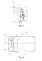
- the spring bolt 2 is shown here with a broken view of the shaft bushing 1 and substantially corresponds to the configuration in the FIGS. 5 and 6 , It can be seen here that the fastening end 17 is deformed for fastening the spring pin 2, that is, the spring pin 2 is formed as Deckelniet.
- a motor vehicle 32 is shown with a drive unit 33, which is arranged with its motor axis 26 transversely to the longitudinal axis 35 in front of the driver's cab 34.
- the drive unit 33 is shown here as an internal combustion engine, which is connected via an output shaft 25 by means of a friction clutch 3 with a drive train 26 shown purely schematically here.
Landscapes
- Engineering & Computer Science (AREA)
- General Engineering & Computer Science (AREA)
- Mechanical Engineering (AREA)
- Mechanical Operated Clutches (AREA)
Applications Claiming Priority (1)
| Application Number | Priority Date | Filing Date | Title |
|---|---|---|---|
| DE102014211060.2A DE102014211060A1 (de) | 2014-06-11 | 2014-06-11 | Schaftbuchse für einen Federbolzen einer Reibkupplung |
Publications (1)
| Publication Number | Publication Date |
|---|---|
| EP2955407A1 true EP2955407A1 (fr) | 2015-12-16 |
Family
ID=53189655
Family Applications (1)
| Application Number | Title | Priority Date | Filing Date |
|---|---|---|---|
| EP15167432.2A Withdrawn EP2955407A1 (fr) | 2014-06-11 | 2015-05-12 | Douille pour boulon à ressort d'un embrayage à friction |
Country Status (2)
| Country | Link |
|---|---|
| EP (1) | EP2955407A1 (fr) |
| DE (1) | DE102014211060A1 (fr) |
Cited By (1)
| Publication number | Priority date | Publication date | Assignee | Title |
|---|---|---|---|---|
| CN112943818A (zh) * | 2019-12-11 | 2021-06-11 | 舍弗勒技术股份两合公司 | 用于扭矩离合器的铰链致动器 |
Citations (6)
| Publication number | Priority date | Publication date | Assignee | Title |
|---|---|---|---|---|
| GB1126911A (en) * | 1965-03-18 | 1968-09-11 | Automotive Prod Co Ltd | Improvements in and relating to friction clutches |
| FR2520823A1 (fr) * | 1982-02-04 | 1983-08-05 | Valeo | Mecanisme d'embrayage a friction muni d'un dispositif perfectionne de limitation de course, notamment pour vehicule automobile |
| FR2538058A1 (fr) * | 1982-12-16 | 1984-06-22 | Valeo | Mecanisme d'embrayage, notamment pour vehicule automobile |
| GB2158530A (en) * | 1984-05-10 | 1985-11-13 | Fichtel & Sachs Ag | Pressure plate unit for a diaphragm spring friction clutch |
| DE102013214702A1 (de) * | 2012-08-24 | 2014-02-27 | Schaeffler Technologies AG & Co. KG | Reibungskupplung |
| DE102014207339A1 (de) * | 2013-05-14 | 2014-11-20 | Schaeffler Technologies Gmbh & Co. Kg | Nietanordnung und Reibungskupplungseinrichtung |
-
2014
- 2014-06-11 DE DE102014211060.2A patent/DE102014211060A1/de not_active Withdrawn
-
2015
- 2015-05-12 EP EP15167432.2A patent/EP2955407A1/fr not_active Withdrawn
Patent Citations (6)
| Publication number | Priority date | Publication date | Assignee | Title |
|---|---|---|---|---|
| GB1126911A (en) * | 1965-03-18 | 1968-09-11 | Automotive Prod Co Ltd | Improvements in and relating to friction clutches |
| FR2520823A1 (fr) * | 1982-02-04 | 1983-08-05 | Valeo | Mecanisme d'embrayage a friction muni d'un dispositif perfectionne de limitation de course, notamment pour vehicule automobile |
| FR2538058A1 (fr) * | 1982-12-16 | 1984-06-22 | Valeo | Mecanisme d'embrayage, notamment pour vehicule automobile |
| GB2158530A (en) * | 1984-05-10 | 1985-11-13 | Fichtel & Sachs Ag | Pressure plate unit for a diaphragm spring friction clutch |
| DE102013214702A1 (de) * | 2012-08-24 | 2014-02-27 | Schaeffler Technologies AG & Co. KG | Reibungskupplung |
| DE102014207339A1 (de) * | 2013-05-14 | 2014-11-20 | Schaeffler Technologies Gmbh & Co. Kg | Nietanordnung und Reibungskupplungseinrichtung |
Cited By (1)
| Publication number | Priority date | Publication date | Assignee | Title |
|---|---|---|---|---|
| CN112943818A (zh) * | 2019-12-11 | 2021-06-11 | 舍弗勒技术股份两合公司 | 用于扭矩离合器的铰链致动器 |
Also Published As
| Publication number | Publication date |
|---|---|
| DE102014211060A1 (de) | 2015-12-17 |
Similar Documents
| Publication | Publication Date | Title |
|---|---|---|
| DE102006048678B4 (de) | Kupplungsvorrichtung | |
| DE102017206513A1 (de) | Gelenkwelle | |
| DE112005002498T5 (de) | Radlager-Stützanordnung | |
| EP2748473B1 (fr) | Articulation à rotule | |
| DE102008043116A1 (de) | Vorrichtung zum Andrücken einer Zahnstange an ein Ritzel | |
| EP2955407A1 (fr) | Douille pour boulon à ressort d'un embrayage à friction | |
| DE102012215395A1 (de) | Kugelgewindetrieb | |
| EP2843252A2 (fr) | Dispositif de protection pour une rondelle conique d'un embrayage à friction doté d'un axe de rotation | |
| DE102011102307A1 (de) | Fixier- und/oder Nachstelleinrichtung, bspw. für stufenlose Verschleißnachstellung einer Kupplung | |
| EP2329161B1 (fr) | Système de joint de cardan pour un arbre de transmission | |
| DE102017119986A1 (de) | Wälzlageranordnung für eine Lenksäule | |
| EP2957789A2 (fr) | Butee de ressort pour systeme d'actionnement d'un embrayage a friction | |
| DE19755496B4 (de) | Abstützring für die Vorlastfeder eines Nehmerzylinders | |
| WO2015144167A2 (fr) | Support de broche pour dispositif de rattrapage | |
| WO2015003701A2 (fr) | Élément d'équilibrage pour équilibrer un embrayage à friction | |
| DE102011016986A1 (de) | Ausrücker für eine gezogene Kupplung | |
| DE102014211023A1 (de) | Kupplungsvorrichtung | |
| EP3123048A2 (fr) | Mécanisme à broche pour dispositif de rattrapage à commande proportionnelle à la course | |
| DE102015219456B3 (de) | Verfahren zur Einstellung eines Betriebspunktes einer Reibungskupplung | |
| EP3234393B1 (fr) | Accouplement sans capot pourvu de boulons creux et d'auxiliaire de centrage | |
| EP2610117B1 (fr) | Système de fixation pour un entraînement d'essuie-glace d'un véhicule automobile | |
| DE102013200524A1 (de) | Pendelstütze | |
| EP2430331B1 (fr) | Structure de connection dans un butée de debrayage et butée de debrayage | |
| EP4217620A1 (fr) | Accouplement amélioré pour applications industrielles, et véhicule ferroviaire | |
| DE102012018054A1 (de) | Elastisches Lager |
Legal Events
| Date | Code | Title | Description |
|---|---|---|---|
| PUAI | Public reference made under article 153(3) epc to a published international application that has entered the european phase |
Free format text: ORIGINAL CODE: 0009012 |
|
| AK | Designated contracting states |
Kind code of ref document: A1 Designated state(s): AL AT BE BG CH CY CZ DE DK EE ES FI FR GB GR HR HU IE IS IT LI LT LU LV MC MK MT NL NO PL PT RO RS SE SI SK SM TR |
|
| AX | Request for extension of the european patent |
Extension state: BA ME |
|
| 17P | Request for examination filed |
Effective date: 20160616 |
|
| RBV | Designated contracting states (corrected) |
Designated state(s): AL AT BE BG CH CY CZ DE DK EE ES FI FR GB GR HR HU IE IS IT LI LT LU LV MC MK MT NL NO PL PT RO RS SE SI SK SM TR |
|
| STAA | Information on the status of an ep patent application or granted ep patent |
Free format text: STATUS: THE APPLICATION HAS BEEN WITHDRAWN |
|
| 18W | Application withdrawn |
Effective date: 20180809 |
|
| P01 | Opt-out of the competence of the unified patent court (upc) registered |
Effective date: 20230523 |