EP2955434B1 - Thermosiphon-lichtmotor und leuchte damit - Google Patents
Thermosiphon-lichtmotor und leuchte damit Download PDFInfo
- Publication number
- EP2955434B1 EP2955434B1 EP15175429.8A EP15175429A EP2955434B1 EP 2955434 B1 EP2955434 B1 EP 2955434B1 EP 15175429 A EP15175429 A EP 15175429A EP 2955434 B1 EP2955434 B1 EP 2955434B1
- Authority
- EP
- European Patent Office
- Prior art keywords
- chamber
- evaporation chamber
- sub
- solid state
- light source
- Prior art date
- Legal status (The legal status is an assumption and is not a legal conclusion. Google has not performed a legal analysis and makes no representation as to the accuracy of the status listed.)
- Active
Links
Images



Classifications
-
- F—MECHANICAL ENGINEERING; LIGHTING; HEATING; WEAPONS; BLASTING
- F21—LIGHTING
- F21V—FUNCTIONAL FEATURES OR DETAILS OF LIGHTING DEVICES OR SYSTEMS THEREOF; STRUCTURAL COMBINATIONS OF LIGHTING DEVICES WITH OTHER ARTICLES, NOT OTHERWISE PROVIDED FOR
- F21V29/00—Protecting lighting devices from thermal damage; Cooling or heating arrangements specially adapted for lighting devices or systems
- F21V29/50—Cooling arrangements
- F21V29/51—Cooling arrangements using condensation or evaporation of a fluid, e.g. heat pipes
-
- F—MECHANICAL ENGINEERING; LIGHTING; HEATING; WEAPONS; BLASTING
- F21—LIGHTING
- F21V—FUNCTIONAL FEATURES OR DETAILS OF LIGHTING DEVICES OR SYSTEMS THEREOF; STRUCTURAL COMBINATIONS OF LIGHTING DEVICES WITH OTHER ARTICLES, NOT OTHERWISE PROVIDED FOR
- F21V29/00—Protecting lighting devices from thermal damage; Cooling or heating arrangements specially adapted for lighting devices or systems
- F21V29/50—Cooling arrangements
- F21V29/56—Cooling arrangements using liquid coolants
-
- F—MECHANICAL ENGINEERING; LIGHTING; HEATING; WEAPONS; BLASTING
- F21—LIGHTING
- F21V—FUNCTIONAL FEATURES OR DETAILS OF LIGHTING DEVICES OR SYSTEMS THEREOF; STRUCTURAL COMBINATIONS OF LIGHTING DEVICES WITH OTHER ARTICLES, NOT OTHERWISE PROVIDED FOR
- F21V5/00—Refractors for light sources
- F21V5/04—Refractors for light sources of lens shape
- F21V5/045—Refractors for light sources of lens shape the lens having discontinuous faces, e.g. Fresnel lenses
-
- F—MECHANICAL ENGINEERING; LIGHTING; HEATING; WEAPONS; BLASTING
- F21—LIGHTING
- F21S—NON-PORTABLE LIGHTING DEVICES; SYSTEMS THEREOF; VEHICLE LIGHTING DEVICES SPECIALLY ADAPTED FOR VEHICLE EXTERIORS
- F21S8/00—Lighting devices intended for fixed installation
- F21S8/04—Lighting devices intended for fixed installation intended only for mounting on a ceiling or the like overhead structures
- F21S8/06—Lighting devices intended for fixed installation intended only for mounting on a ceiling or the like overhead structures by suspension
-
- F—MECHANICAL ENGINEERING; LIGHTING; HEATING; WEAPONS; BLASTING
- F21—LIGHTING
- F21V—FUNCTIONAL FEATURES OR DETAILS OF LIGHTING DEVICES OR SYSTEMS THEREOF; STRUCTURAL COMBINATIONS OF LIGHTING DEVICES WITH OTHER ARTICLES, NOT OTHERWISE PROVIDED FOR
- F21V13/00—Producing particular characteristics or distribution of the light emitted by means of a combination of elements specified in two or more of main groups F21V1/00 - F21V11/00
- F21V13/02—Combinations of only two kinds of elements
- F21V13/04—Combinations of only two kinds of elements the elements being reflectors and refractors
-
- F—MECHANICAL ENGINEERING; LIGHTING; HEATING; WEAPONS; BLASTING
- F21—LIGHTING
- F21V—FUNCTIONAL FEATURES OR DETAILS OF LIGHTING DEVICES OR SYSTEMS THEREOF; STRUCTURAL COMBINATIONS OF LIGHTING DEVICES WITH OTHER ARTICLES, NOT OTHERWISE PROVIDED FOR
- F21V29/00—Protecting lighting devices from thermal damage; Cooling or heating arrangements specially adapted for lighting devices or systems
- F21V29/50—Cooling arrangements
- F21V29/56—Cooling arrangements using liquid coolants
- F21V29/58—Cooling arrangements using liquid coolants characterised by the coolants
-
- F—MECHANICAL ENGINEERING; LIGHTING; HEATING; WEAPONS; BLASTING
- F21—LIGHTING
- F21Y—INDEXING SCHEME ASSOCIATED WITH SUBCLASSES F21K, F21L, F21S and F21V, RELATING TO THE FORM OR THE KIND OF THE LIGHT SOURCES OR OF THE COLOUR OF THE LIGHT EMITTED
- F21Y2115/00—Light-generating elements of semiconductor light sources
- F21Y2115/10—Light-emitting diodes [LED]
Definitions
- the present invention relates to lighting, and more specifically, to light engines and luminaire incorporating one or more active cooling elements.
- Solid state light sources offer tremendous advantages over conventional lighting technologies. Of course, some of those advantages come at a cost.
- One cost of using solid state light sources is that solid state light sources generate heat, sometimes tremendous amounts of heat.
- lamps and luminaires that use solid state light sources include thermal management systems, such as but not limited to metal heat sinks. These metal heat sinks are typically large and heavy, including a number of fins to increase surface area and thus dissipate more heat. The larger the heat sink, the more heat that is able to be dissipated, and the more solid state light sources and/or the higher power solid state light sources are able to be used in the lamp or luminaire.
- a more traditionally sized lamp profile e.g., a classic A19 Edison light bulb
- a more traditionally sized luminaire space e.g., a six-inch ceiling can.
- thermal management systems based on active cooling elements (e.g., small fans that circulate air through the lamp/luminaire) and thermal management systems based on one or more cooling liquids.
- active cooling elements e.g., small fans that circulate air through the lamp/luminaire
- thermal management systems based on one or more cooling liquids.
- the liquid may be passed over or around the solid state light sources, gathering heat, and then, in an active system incorporating a pump or similar device, taken away and cooled, and then returned.
- the cooling liquid may be heated and evaporated, and then condensed, as in a conventional thermosyphon.
- DE 102007054039 A1 discusses a light emitting diode having a liquid light converter for adapting the color of light.
- EP 1475846 A1 discusses a light source apparatus including a non-light emitting face side of a LED chip, opposite to a light emitting side, which is exposed to a liquid for cooling.
- US 20090213613 A1 discusses a motor vehicle headlight including a heat pipe or a thermosiphon an evaporation region.
- the heat pipe or the thermosiphon has an evaporation region. In the evaporation region, the heat pipe or the thermosiphon absorbs heat.
- Embodiments described herein provide a new use for a cooling element that incorporates a liquid, such as a thermosyphon.
- Embodiments described herein provide a thermosyphon light engine that (i) cools one or more solid state light sources, such as but not limited to light emitting diodes (LEDs), organic LEDs (OLEDs), PLEDs, and the like, including combinations thereof, and (ii) helps control and redirect light emitted by the one or more solid state light sources.
- Further embodiments apply the thermosyphon light engine to luminaires, where the thermosyphon light engine cools not only one or more solid state light sources but also other heat-generating elements of the luminaire (e.g., a power source).
- a light engine includes: a condenser, wherein the condenser returns a gaseous substance located therein to a liquid substance; an evaporation chamber including a wall, the wall having a first portion and a second portion, wherein the evaporation chamber includes: at least one solid state light source that emits light and generates heat upon activation; a working liquid into which at least a portion of the solid state light source is immersed, wherein the working liquid is capable of being changed into a gaseous substance upon the application of heat to the working liquid; and an optical element formed in the first portion of the wall of the evaporation chamber, wherein the optical element beam shapes light emitted by the at least one solid state light source; and wherein the second portion of the wall of the evaporation chamber is shaped to enhance the directional effects of the optical element; and at least one connecting element that joins the condenser to the evaporation chamber, such that when the at least one solid state light source in the
- the optical element and the at least one solid state light source may be correspondingly shaped so that the at least one solid state light source rests adjacent to the optical element on an interior surface of the evaporation chamber.
- the evaporation chamber may further include: a support element, wherein the support element may hold the at least one solid state light source in a particular position within the evaporation chamber.
- the support element may hold the at least one solid state light source in a particular position within the evaporation chamber when the at least one solid state light source is immersed within the working liquid.
- the evaporation chamber may be shaped to include an interior portion and an exterior portion, wherein the interior portion includes the at least one solid state light source, the working liquid, and the optical element, and wherein the exterior portion includes a reflector.
- the evaporation chamber may include a plurality of sub-chambers, wherein each sub-chamber in the plurality of sub-chambers may include a solid state light source, a working liquid, and an optical element.
- each sub-chamber in the plurality of sub-chambers may be shaped to achieve a particular optical effect in combination with the optical element of that sub-chamber.
- each sub-chamber may have a wall; wherein the optical element of each sub-chamber may be formed in a first portion of the wall of the respective sub-chamber; and wherein a second portion of the wall of the sub-chamber may be shaped so as to enhance the directional effects of the light passing through the optical element of the respective sub-chamber.
- a first sub-chamber in the plurality of sub-chambers may be fixed in a particular direction relative to a second sub-chamber in the plurality of sub-chambers, such that at least a portion of the light beam shaped by the optical element of the first sub-chamber travels in the particular direction.
- the working liquid of a given sub-chamber may be unable to pass into another sub-chamber in liquid form.
- the light engine may include a plurality of evaporation chambers, wherein the plurality of evaporation chambers may be connected to the condenser by the at least one connecting element.
- the light engine may include a plurality of condensers, wherein each evaporation chamber in the plurality of evaporation chambers may have a corresponding condenser in the plurality of condensers.
- the working liquid may have a measurable refractive index that works in combination with the optical element to beam shape the light emitted by the at least one solid state light source.
- a luminaire in another embodiment, there is provided a luminaire.
- the luminaire includes: a power source; at least one light source, wherein the at least one light source receives power from the power source; a thermosyphon light engine, including: a condenser, wherein the condenser returns a gaseous substance located therein to a liquid substance; an evaporation chamber, wherein the evaporation chamber includes: at least one solid state light source that emits light and generates heat upon activation; a working liquid into which at least a portion of the solid state light source is immersed, wherein the working liquid is capable of being changed into a gaseous substance upon the application of heat to the working liquid; and an optical element, wherein the optical element beam shapes light emitted by the at least one solid state light source; and at least one connecting element that joins the condenser to the evaporation chamber, such that when the at least one solid state light source in the evaporation chamber generates heat, a portion of the working liquid evaporates
- the luminaire may include a plurality of light sources located in relation to the thermosyphon light engine, wherein the luminaire may be shaped such that the condenser and the at least one connecting element of the thermosyphon light engine, and the luminaire evaporation chamber and the at least one luminaire connecting element, are concealed from view.
- a portion of the evaporation chamber of the thermosyphon light engine that includes at least a portion of the optical element may be visible in relation to the plurality of light sources.
- FIG. 1 shows a thermosyphon light engine 100.
- the thermosyphon light engine 100 includes an evaporation chamber 102, a condenser 104, and connecting elements 106, 108.
- the condenser is any device capable of receiving a gaseous substance and/or a substantially gaseous substance as an input and returning it to a liquid substance and/or a substantially liquid substance.
- the connecting elements 106, 108 may include, but are not limited to, tubes and/or other transmission elements or components capable of carrying a liquid and/or a suspension and/or a gas and/or a so-called "nano-fluid" and/or combinations thereof.
- the evaporation chamber 102 is filled with a working liquid 120.
- the working liquid 120 is any type of liquid, including a suspension and/or a so-called “nano-fluid", that is capable of being stored in the evaporation chamber 102 and able to cool at least one solid state light source (such as but not limited to an LED module 112 shown in FIG. 1 ) that is also located within the evaporation chamber 102.
- a solid state light source such as but not limited to an LED module 112 shown in FIG. 1
- the working liquid 120 within the thermosyphon in some embodiments is, but is not limited to, PF5060 manufactured by 3M®.
- PF5060 has a low boiling point (56 °C at normal atmospheric pressure) that is critical in maintaining the junction temperature of the at least one solid state light source as low as possible.
- water, various alcohols, various synthetic liquids, and/or combinations of any of these, are used. Indeed, any liquid with a low boiling point (in some embodiments, 60 °C or less) is able to be used as the working liquid 120.
- the primary consideration in selecting a working liquid 120 depends on how low the junction temperature of the at least one solid state light source is desired to be.
- the junction temperature of the at least one solid state light source depends on, for example, the substrate used and/or the particular module used that incorporates the at least one solid state light source.
- the lower bound on the temperature of the working liquid 120 is as close to zero degrees Celsius (i.e., freezing) as possible.
- the working liquid 120 may be frozen and then melted by the heat generated by the at least one solid state light source when the solid state light source receives power.
- the lower bound on the temperature of the working liquid 120 is substantially 30 °C to control the pressure within the thermosyphon light engine 100.
- the evaporation chamber 102 includes an optical element 110.
- the optical element 110 beam shapes light emitted by the at least one solid state light source located within the evaporation chamber 102.
- the optical element 110 may be any type of known lens, such as but not limited to a batwing lens, Fresnel lens, and the like.
- the optical element 110 in some embodiments, is shaped from the material comprising the evaporation chamber. Alternatively, or additionally, the optical element 110 is a separate component that is joined to the evaporation chamber 102, for example but not limited to via a recessed opening or other known connection type.
- the optical element 110 includes a plurality of optical elements, such as but not limited to any type of lens, including combinations thereof. Though shown in FIG. 1 as occupying only a portion of an outer edge of the evaporation chamber 102, the optical element 110 may be larger such that the optical element 110 occupies the entirety of a visible edge of the evaporation chamber 102. Alternatively or additionally, in some embodiments, a plurality of optical elements (not shown in FIG. 1 ) occupy the entirety of the visible edge of the evaporation chamber 102.
- the evaporation chamber 102 also includes at least one solid state light source, such as but not limited to the LED 112 shown in FIG. 1 , as described above.
- the at least one solid state light source includes any of a single LED (such as the LED 112 shown in FIG. 1 ), an array of LEDs on a single chip, a plurality of LED chips, and combinations thereof.
- the at least one solid state light source is mounted on a substrate (e.g., a metal core printed circuit board, though other types of substrates may of course be used) along with appropriate electronic components that allow the at least one solid state light source to operate.
- the at least one solid state light source is at least partially submerged (i.e., immersed) into the working liquid 120 that fills at least a portion of the evaporator chamber 102.
- the entirety of the at least one solid state light source is immersed.
- only a portion of the at least one solid state light source is immersed in the working liquid 120. For example, by covering the "back side" of the at least one solid state lights source (i.e., the portion that does not include the light emitting element(s)), at least in part with the working liquid 120, heat generated by the at least one solid state light source will be dissipated.
- the at least one solid state light source may have a primary lens and/or lenses and/or reflectors (and/or combinations thereof) of its own.
- the at least one solid state light source is sealed with a sealant, such as but not limited to DOW® Corning® 3145 RTV silicone adhesive, to provide various advantages, such as but not limited to the sealant blocking the working liquid 120 from interfering with the operation of the at least one solid state light source.
- the thermosyphon light engine 100 operates as follows. When the at least one solid state light source is activated and begins to emit light, the at least one solid state light source generates heat. The heat causes the working liquid 120 within the evaporation chamber 102 to begin to increase in temperature, until the working liquid 120 begins to boil. As the working liquid 120 boils, some portion of the working liquid 120 is changed into a gaseous substance and/or a substantially gaseous substance. In other words, a portion of the working liquid 120 evaporates. The resulting gaseous substance and/or substantially gaseous substance travels through one of the connecting elements 106, 108 to the condenser 104.
- the condenser 104 returns the resulting gaseous substance and/or substantially gaseous substance back to a liquid substance (and/or substantially liquid substance) (i.e., the working liquid 120).
- the liquid substance then travels through the one of the connecting elements 106, 108 back to the evaporation chamber 102. This process runs continually so long as there is heat being generated to cause the working liquid 120 to evaporate, and so long as the evaporation chamber 102 includes enough working liquid 120 to maintain the at least one solid state light source at a particular junction temperature.
- the so-called "back side" of the at least one solid state light source is specially prepared to ensure that the boiling process (i.e., evaporation) begins when the at least one solid state light source receives power, is activated, and begins to generate heat.
- the boiling process i.e., evaporation
- one or more channels and/or grooves are scored or otherwise created on the "back side".
- a sintered material may be used.
- the "back side” may be machine, and/or pre-machined at the time of manufacture, to include one or more grooves and/or channels.
- a secondary material that is particularly amenable to encouraging and/or enhancing the boiling process may be added. Any additions and/or alterations to the at least one solid state light source that enhance the boiling process (i.e., evaporation) assist in the maintenance of the cooling process performed by the thermosyphon.
- the optical element 110 and the at least one solid state light source are correspondingly shaped, so that the at least one solid state light source rests adjacent to the optical element 110 on an interior surface of the evaporation chamber 102.
- the working liquid 120 may be chosen because it exhibits one or more particular optical characteristics. Such an optical characteristic and/or characteristics may be particularly chosen to interact with the optical element 1 10 in a desired way.
- the working liquid 120 may be, in some embodiments, clear, substantially clear (i.e., translucent), and/or substantially opaque.
- the working liquid 120 may have a particular color and/or a known or measurable refractive index.
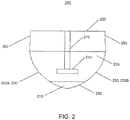
- FIG. 2 shows a cross-sectional view of a portion 200 of an evaporation chamber 202 of a thermosyphon light engine.
- the evaporation chamber 202 has an exterior wall 250.
- the optical element 210 is formed in a first portion of the exterior wall 250.
- a second portion 252A, 252B of the exterior wall 250 is shaped so as to enhance the directional effects of the optical element 210.
- the second portion 252A, 252B are shaped so as to collimate light generated by an LED 212 in addition to the beam shaping performed by the optical element 210.
- the second portion 252A, 252B (and thus the exterior wall 250) of the evaporation chamber 202 may be shaped in any way to achieve one or more particular optical effects, either alone or in combination with the optical element 210.
- the second portion 252A, 252B in some embodiments, is made of a reflective element and/or coated with a reflective coating to help direct light to the optical element 210.
- the evaporation chamber 202 is made from a particular material and/or materials.
- the evaporation chamber 202 may be made from a material that is clear (i.e., transparent), or translucent, or in some embodiments perhaps even substantially opaque. Whatever material is used should allow light to exit the evaporation chamber 202 through at least the optical element 210.
- the evaporation chamber 202 in some embodiments, is made entirely of one material (for example but not limited to plastic), and other embodiments, is partially made from a first material and partially made from one or more other materials (e.g., the side walls (i.e., second portion 252A, 252B) could be reflective materials, or a metalized plastic, etc.).
- the evaporation chamber 202 in some embodiments, itself is modular, such that it would be possible to swap out one kind and/or shape of evaporation chamber for another. In such embodiments, it is important to have a good seal between the evaporation chamber 202 and any connecting elements (such as connecting elements 106, 108 shown in FIG. 1 ). Further, in some embodiments, the evaporation chamber 202 may be of any shape or size, so long as it is capable of holding the at least one solid state light source and the working liquid.
- FIG. 2 also shows a support element 270.
- the support element 270 holds the at least one solid state light source (i.e., the LED 212) in a particular position within the evaporation chamber 202.
- the support element 270 is particularly useful when the evaporation chamber 202 is not located in a direction leads to gravity keeping the at least one solid state light source and/or working liquid 220 in contact with each other.
- the support element 270 holds the at least one solid state light source in a particular position within the evaporation chamber 202 when the at least one solid state light source is immersed within the working liquid 220.
- FIG. 3 shows a thermosyphon light engine 300 where side walls 352A, 352B of an evaporation chamber 302 are shaped so as to extend beyond an optical element 310.
- the side walls 352A, 352B serve as reflectors (i.e., mechanical and optical cutoffs for the light emitted through the optical element 310).
- the evaporation chamber 302 includes an inner portion 380 and an outer portion 390.
- the inner portion 380 includes at least one solid state light source 312, the working liquid 320, and the optical element 310.
- the outer portion 390 includes the extended side walls 352A, 352B.
- FIGs. 4 and 5 show cross-sectional views of thermosyphon light engines 400 and 500, respectively, that include more than one evaporation chamber and/or a plurality of sub-chambers.
- the thermosyphon light engine 400 includes three sub-chambers 402A, 402B, and 402C that are all part of an evaporation chamber 402.
- Each sub-chamber 402A, 402B, and 402C includes a solid state light source 412A, 412B, and 412C, a working liquid 420, and an optical element 410A, 410B, and 410C.
- each sub-chamber 402A, 402B, and 402C may include its own working liquid (as shown in FIG.
- the working liquid of a given sub-chamber is unable to pass into another sub-chamber in liquid form.
- the gaseous form of the working liquid may, and in some embodiments, is, able to pass from one sub-chamber into another.
- each sub-chamber 402A, 402B, and 402C in the plurality of sub-chambers are of the same and/or substantially the same shape.
- each sub-chamber 402A, 402B, and 402C in the plurality of sub-chambers is shaped to achieve a particular optical effect in combination with the optical element of that particular sub-chamber.
- some subset of the plurality of sub-chambers may each have a first shape, while some other subset of the plurality of sub-chambers have a second shape, where the first shape is different from the second shape. Endless combinations of differently shaped sub-chambers are possible.
- each sub-chamber may also have other distinctive characteristics, such as those described in relation to any evaporation chamber described herein.
- each sub-chamber 402A, 402B, and 402C there is a condenser 404A, 404B, and 404C.
- a sub-chamber in some embodiments, is matched to a particular condenser, such that the sub-chamber is itself considered to be an evaporation chamber, and each sub-chamber thus has a corresponding condenser.
- a sub-chamber/chamber and a condenser are connected by a connecting element (i.e., one of connecting elements 406A, 406B, 406C, 408A, 408B, and/or 408C).
- the ratio between condensers and solid state light sources may be one to one, and the ratio may be the same between evaporation chambers and what is being cooled. That is, for a single LED module, some embodiments may use a single condenser and a single evaporation chamber. Similarly, for a single LED array, some embodiments may use a single condenser and a single evaporation chamber.
- thermosyphon light engine(s) where a number of luminaires including thermosyphon light engine(s) are in a location (e.g., a room), and where each luminaire includes its own LED array/module, the ratio between luminaires and condensers/evaporation chambers may again be 1 : 1.
- a higher ratio of light source/elements containing light sources to thermosyphon components may be used.
- the thermosyphon light engine 500 shown in FIG. 5 also includes a plurality of evaporation chambers 502 A, 502B, and 502C (which may also be referred to as sub-chambers). However, here each evaporation chamber 502A, 502B, and 502C are fixed in different directions. That is, the evaporation chamber 502A is fixed in a direction opposite the a direction of the evaporation chamber 502C, while the evaporation chamber 502B is fixed in a direction that is perpendicular to the direction of either the evaporation chamber 502 A or the evaporation chamber 502C.
- thermosyphon light engine By fixing the direction of one or more evaporation chambers in this way, it is possible to further guide light emitted by at least one solid state light source contained therein, through the optical element of that evaporation chamber, in a particular direction. This gives a lighting designer looking to use a thermosyphon light engine, either as a lighting module on its own or as part of a luminaire, a great deal of flexibility, while providing the same optical and thermal advantages.
- Each evaporation chamber 502A, 502B, and 502C as shown in FIG. 5 include their own respective working liquid 520A, 520B, and 520C, as well as their own respective solid state light source 512A, 512B, and 512C, and respective optical element 510A, 510B, and 5 IOC.
- Each evaporation chamber 502 A, 502B, and 502C is able to be configured differently, or similarly, or the same as any other evaporation chamber.
- the solid state light source 512A is adapted to sit directly adjacent to the optical element 510A in the evaporation chamber 502A.
- the optical element 512B is of a different size than the optical element 510A.
- the evaporation chamber 502C itself is of a different shape that the evaporation chamber 502B. All of the evaporation chambers 502A, 502B, and 502C are served by the same condenser 504 and connecting elements 506 and 508.
- FIG. 6 shows a luminaire 600 including a thermosyphon light engine 601 as well as at least one n additional light source 660.
- the at least one additional light source 660 may be a conventional light source (i.e., an incandescent, fluorescent, and/or halogen lamp and/or luminaire include such a lamp), or may be a solid state light source (either a lamp and/or a retrofit lamp, and/or a luminaire including such a lamp and/or retrofit lamp).
- the at least one additional light source 660 includes at least one, and in some embodiments, a plurality of, light sources 660A, 660B.
- the luminaire 600 also includes a power source 675. The power source provides power to at least one additional light source 660.
- the thermosyphon light engine 601 includes a condenser 604, an evaporation chamber 602, and connecting elements 606 and 608, all as described herein.
- the evaporation chamber 602 includes at least one solid state light source 612, a working liquid 620, and an optical element 610, all as described herein.
- the luminaire additionally includes a luminaire evaporation chamber 676, which itself including a working liquid 677, and at least one luminaire connecting element 678.
- the at least one luminaire connecting element 678 connects the luminaire evaporation chamber 676 to the condenser 604 of the thermosyphon light engine 601.
- the working liquid 677 within the luminaire evaporation chamber 676 is heated by heat generated by at least one of the power source 675 and the at least one additional light source 660, the working liquid 677 begins to evaporate into a gaseous substance, which travels through the at least one luminaire connecting element 678 to the condenser 604.
- the condenser 604 returns the gaseous substance to a liquid form, which travels back to the luminaire evaporation chamber 676 via the at least one luminaire connecting element 678.
- the luminaire evaporation chamber 676 has its own condenser (not shown in FIG. 6 ) that is separate from the condenser of the thermosyphon light engine 601.
- a plurality of luminaires and/or components thereof may share one or more condensers via a plurality of connecting elements.
- the plurality of light sources 660A, 660B are located in relation to the thermosyphon light engine 601.
- the luminaire 600 is shaped such that the condenser 604 and the connecting elements 606, 608 of the thermosyphon light engine 601, and the luminaire evaporation chamber 676 and the at least one luminaire connecting element 678, are concealed from view. For example, these may be sealed in a housing, such as the housing 679 shown in FIG. 6 .
- a portion of the evaporation chamber 602 of the thermosyphon light engine 601 that includes at least a portion of the optical element 610 is visible in relation to the plurality of light sources 660A, 660B.
- the at least one additional light source 660 is located at least partially within the luminaire evaporation chamber 676, and the luminaire evaporation chamber 676 includes its own optical element that beam shapes light emitted by the at least one additional light source 660.
- thermosyphon light engine When placed into a luminaire, a thermosyphon light engine as described herein may be used as a general illumination source or as accent lighting, or in combinations thereof. This may be done by directly shaping a surface of the luminaire to include one or more protruding thermosyphon light engines.
- the thermosyphon light engine may also provide cooling to the solid state lighting elements and/or other lighting elements and/or power supply(ies) and/or other heat-generating components associated with the luminaire.
- a luminaire is mounted in a ceiling, or otherwise attached thereto, including one or more light sources and one or more thermosyphon light engines.
- One or more of the light sources may be separate from the one or more thermosyphon light engines, such that the one or more thermosyphon light engines serve as separate light-generating elements from the one or more light sources.
- the light sources may be a number of pendant fixtures attached to a ceiling tile, which in total is considered to be a luminaire, and the one or more thermosyphon light engines may be embedded within the ceiling tile, and may serve as a general illumination source (along with the pendant fixtures) or as accent lighting.
- the light sources and the thermosyphon light engines may be combined together, such that the thermosyphon light engines include the light sources, and the only source of illumination from the luminaire is the one or more thermosyphon light engines.
- the luminaire may receive power in any known way, such as but not limited to via a power source and/or a power supply, whether transmitted to the luminaire via wire or wirelessly, as is known in the art.
- the power source, power supply, and/or transmission element(s) may be, and in some embodiments, is/are, cooled using a thermosyphon (i.e., evaporation chamber, condenser, and connecting element(s)), either separate from the one or more thermosyphon light engines or otherwise connected thereto.
- a thermosyphon i.e., evaporation chamber, condenser, and connecting element(s)
- the luminaire instead of the luminaire being a ceiling tile with a number of pendant fixtures and thermosyphon light engines attached thereto, the luminaire itself may include both a traditional luminaire (e.g., a fixture including one or more light sources) and one or more thermosyphon light engines.
- the luminaire may be a ceiling-mounted fixture, such as but not limited to a flush mounted fixture, where the optical element facing down includes one or more thermosyphon light engines.
- the luminaire may be wall mounted instead of ceiling mounted, and the thermosyphon light engines are designed such that the working liquid(s) contained therein remain around the light sources contained therein.
Landscapes
- Engineering & Computer Science (AREA)
- General Engineering & Computer Science (AREA)
- Non-Portable Lighting Devices Or Systems Thereof (AREA)
- Arrangement Of Elements, Cooling, Sealing, Or The Like Of Lighting Devices (AREA)
Claims (15)
- Licht-Funktionseinheit (100), aufweisend:einen Kondensierer (104), wobei der Kondensierer (104) eine gasförmige Substanz, die sich darin befindet, in eine flüssige Substanz zurückführt;eine Verdampfungskammer (102), die eine Wand aufweist, wobei die Wand einen ersten Abschnitt und einen zweiten Abschnitt aufweist, wobei die Verdampfungskammer (102) aufweist:zumindest eine Festkörperlichtquelle (112), die bei Aktivierung Licht emittiert und Wärme erzeugt;eine Arbeitsflüssigkeit (120), in die zumindest ein Teil der Festkörperlichtquelle (112) eingetaucht ist, wobei die Arbeitsflüssigkeit (120) dazu in der Lage ist, bei der Anwendung von Wärme auf die Arbeitsflüssigkeit (120) in eine gasförmige Substanz geändert zu werden; undein optisches Element (110), das in dem ersten Abschnitt der Wand der Verdampfungskammer gebildet ist, wobei das optische Element (110) Licht, das durch die zumindest eine Festkörperlichtquelle (112) emittiert wird, strahlformt; und wobei der zweite Abschnitt der Wand der Verdampfungskammer (102) geformt ist, um die gerichteten Effekte des optischen Elements (110) zu steigern,zumindest ein Verbindungselement (106, 108), das den Kondensierer (104) mit der Verdampfungskammer (102) verbindet, so dass, wenn die zumindest eine Festkörperlichtquelle (112) in der Verdampfungskammer (102) Wärme erzeugt, ein Teil der Arbeitsflüssigkeit (120) verdampft, wobei sie eine gasförmige Substanz wird, wobei sich die gasförmige Substanz durch das zumindest eine Verbindungselement (106, 108) zu dem Kondensierer (104) bewegt, und wobei sie dabei in eine flüssige Substanz zurückgeführt wird, wobei sich die flüssige Substanz durch das zumindest eine Verbindungselement (106, 108) zurück in die Verdampfungskammer (102) bewegt.
- Licht-Funktionseinheit (100) nach Anspruch 1, wobei das optische Element (110) und die zumindest eine Festkörperlichtquelle (112) übereinstimmend geformt sind, so dass die zumindest eine Festkörperlichtquelle (112) angrenzend an das optische Element (110) auf einer Innenoberfläche der Verdampfungskammer (102) ruht.
- Licht-Funktionseinheit (100) nach Anspruch 1, wobei die Verdampfungskammer (102) ferner aufweist:ein Stützelement, wobei das Stützelement die zumindest eine Festkörperlichtquelle (112) in einer bestimmten Position innerhalb der Verdampfungskammer (102) hält;wobei das Stützelement bevorzugt die zumindest eine Festkörperlichtquelle (112) in einer bestimmten Position innerhalb der Verdampfungskammer (102) hält, wenn die zumindest eine Festkörperlichtquelle (112) innerhalb der Arbeitsflüssigkeit (120) eingetaucht ist.
- Licht-Funktionseinheit (100) nach Anspruch 1,
wobei die Verdampfungskammer (102) geformt ist, um einen Innenteil und einen Außenteil aufzuweisen,
wobei der Innenteil die zumindest eine Festkörperlichtquelle (112), die Arbeitsflüssigkeit (120) und das optische Element (110) aufweist, und wobei der Außenteil einen Reflektor aufweist. - Licht-Funktionseinheit (100) nach Anspruch 1,
wobei die Verdampfungskammer (102) mehrere Teilkammern aufweist, wobei jede Teilkammer in den mehreren Teilkammern eine Festkörperlichtquelle (112), eine Arbeitsflüssigkeit (120) und ein optisches Element (110) aufweist. - Licht-Funktionseinheit (100) nach Anspruch 5,
wobei jede Teilkammer in den mehreren Teilkammern geformt ist, um in Kombination mit dem optischen Element (110) dieser Teilkammer einen bestimmten optischen Effekt zu erzielen. - Licht-Funktionseinheit (100) nach Anspruch 6,
wobei jede Teilkammer eine Wand aufweist;
wobei das optisches Element (110) jeder Teilkammer, in einem ersten Abschnitt der Wand der entsprechenden Teilkammer gebildet ist; und
wobei ein zweiter Abschnitt der Wand der Teilkammer, so geformt ist, dass die gerichteten Effekte des Lichts, welches durch das optische Element (110) der entsprechenden Teilkammer, hindurch geht, gesteigert werden. - Licht-Funktionseinheit (100) nach Anspruch 5,
wobei eine erste Teilkammer der mehreren Teilkammern in einer bestimmten Richtung relativ zu einer zweiten Teilkammer in den mehreren Teilkammern fixiert ist, so dass sich zumindest ein Teil des Lichts, das durch das optische Element (110) der ersten Teilkammer strahlgeformt wird, in der bestimmten Richtung bewegt. - Licht-Funktionseinheit (100) nach Anspruch 5,
wobei die Arbeitsflüssigkeit (120) einer gegebenen Teilkammer nicht dazu in der Lage ist, sich in flüssiger Form in eine andere Teilkammer zu bewegen. - Licht-Funktionseinheit (100) nach Anspruch 1,
die mehrere Verdampfungskammern (102) aufweist,
wobei die mehreren Verdampfungskammern (102) mittels des zumindest einen Verbindungselements (106, 108) mit dem Kondensierer (104) verbunden sind. - Licht-Funktionseinheit (100) nach Anspruch 10,
die mehrere Kondensierer (104) aufweist,
wobei jede Verdampfungskammer (102) in den mehreren Verdampfungskammern (102) einen entsprechenden Kondensierer (104) in den mehreren Kondensierern (104) aufweist. - Licht-Funktionseinheit (100) nach Anspruch 1,
wobei die Arbeitsflüssigkeit (120) einen messbaren Brechungsindex aufweist, der in Kombination mit dem optischen Element (110) arbeiten, um das Licht, das von der zumindest einen Festkörperlichtquelle (112) emittiert wird, strahlzuformen. - Leuchte (600), die Folgendes aufweist:eine Leistungsquelle (675);zumindest eine Lichtquelle (112), wobei die zumindest eine Lichtquelle (112) Leistung von der Leistungsquelle (675) empfängt;eine Thermosiphon-Licht-Funktionseinheit (100) nach einem der Ansprüche 1 bis 12;eine Leuchte-Verdampfungskammer (102), die eine Arbeitsflüssigkeit (120) aufweist; undzumindest ein Leuchte-Verbindungselement (106, 108);wobei die Arbeitsflüssigkeit (120) innerhalb der Leuchte-Verdampfungskammer (102) durch Wärme erwärmt wird, die von zumindest einem von der Leistungsquelle und der zumindest eine Lichtquelle (112) erzeugt wird, und wobei das zumindest eine Leuchte-Verbindungselement (106, 108) die Leuchte-Verdampfungskammer (102) mit dem Kondensierer (104) der Thermosiphon-Licht-Funktionseinheit (100) verbindet.
- Leuchte (600) nach Anspruch 13,
die mehrere Lichtquellen (112) aufweist, die in Bezug zu der Thermosiphon-Licht-Funktionseinheit (100) angeordnet sind, wobei die Leuchte (600) geformt ist, so dass der Kondensierer (104) und das zumindest eine Verbindungselement (106, 108) der Thermosiphon-Licht-Funktionseinheit (100) und die Leuchte-Verdampfungskammer (102) und das zumindest eine Leuchte-Verbindungselement (106, 108) vor einem Blick verborgen sind. - Leuchte (600) nach Anspruch 14,
wobei ein Teil der Verdampfungskammer (102) der Thermosiphon-Licht-Funktionseinheit (100), der zumindest einen Teil des optischen Elements (110) aufweist, in Bezug auf die mehreren Lichtquellen (112) sichtbar ist.
Applications Claiming Priority (4)
| Application Number | Priority Date | Filing Date | Title |
|---|---|---|---|
| US33056710P | 2010-05-03 | 2010-05-03 | |
| EP11778221.9A EP2567150B1 (de) | 2010-05-03 | 2011-05-03 | Thermosiphon-lichtmotor und leuchtmittel damit |
| US13/100,294 US8602590B2 (en) | 2010-05-03 | 2011-05-03 | Thermosyphon light engine and luminaire including same |
| PCT/US2011/035081 WO2011140157A1 (en) | 2010-05-03 | 2011-05-03 | Thermosyphon light engine and luminaire including same |
Related Parent Applications (2)
| Application Number | Title | Priority Date | Filing Date |
|---|---|---|---|
| EP11778221.9A Division-Into EP2567150B1 (de) | 2010-05-03 | 2011-05-03 | Thermosiphon-lichtmotor und leuchtmittel damit |
| EP11778221.9A Division EP2567150B1 (de) | 2010-05-03 | 2011-05-03 | Thermosiphon-lichtmotor und leuchtmittel damit |
Publications (2)
| Publication Number | Publication Date |
|---|---|
| EP2955434A1 EP2955434A1 (de) | 2015-12-16 |
| EP2955434B1 true EP2955434B1 (de) | 2019-09-11 |
Family
ID=44858120
Family Applications (2)
| Application Number | Title | Priority Date | Filing Date |
|---|---|---|---|
| EP15175429.8A Active EP2955434B1 (de) | 2010-05-03 | 2011-05-03 | Thermosiphon-lichtmotor und leuchte damit |
| EP11778221.9A Active EP2567150B1 (de) | 2010-05-03 | 2011-05-03 | Thermosiphon-lichtmotor und leuchtmittel damit |
Family Applications After (1)
| Application Number | Title | Priority Date | Filing Date |
|---|---|---|---|
| EP11778221.9A Active EP2567150B1 (de) | 2010-05-03 | 2011-05-03 | Thermosiphon-lichtmotor und leuchtmittel damit |
Country Status (6)
| Country | Link |
|---|---|
| US (2) | US8602590B2 (de) |
| EP (2) | EP2955434B1 (de) |
| KR (1) | KR101554542B1 (de) |
| CN (1) | CN102859275A (de) |
| CA (1) | CA2797993C (de) |
| WO (1) | WO2011140157A1 (de) |
Families Citing this family (11)
| Publication number | Priority date | Publication date | Assignee | Title |
|---|---|---|---|---|
| US8217557B2 (en) * | 2010-08-31 | 2012-07-10 | Micron Technology, Inc. | Solid state lights with thermosiphon liquid cooling structures and methods |
| CN103322434A (zh) * | 2012-03-20 | 2013-09-25 | 浙江思朗照明有限公司 | 一种发光二极管灯具 |
| TWM468784U (zh) * | 2013-08-16 | 2013-12-21 | Arc Solid State Lighting Corp | 光源模組及應用此光源模組的發光組件 |
| US9318360B2 (en) * | 2013-10-11 | 2016-04-19 | Applied Materials, Inc. | Linear high packing density for LED arrays |
| TWM484672U (zh) * | 2014-04-16 | 2014-08-21 | Arc Solid State Lighting Corp | 可變化角度之相變化光源模組 |
| US9401468B2 (en) | 2014-12-24 | 2016-07-26 | GE Lighting Solutions, LLC | Lamp with LED chips cooled by a phase transformation loop |
| CN104593731B (zh) * | 2015-02-04 | 2017-05-03 | 深圳市华星光电技术有限公司 | 蒸镀换料一体化设备及其使用方法 |
| TWI582342B (zh) * | 2015-06-05 | 2017-05-11 | 錦鑫光電股份有限公司 | 相變化散熱裝置及燈具 |
| TWI551817B (zh) * | 2015-06-05 | 2016-10-01 | 錦鑫光電股份有限公司 | 相變化散熱裝置及燈具 |
| CN109790047B (zh) * | 2016-09-20 | 2022-09-20 | 可乐丽则武齿科株式会社 | 氧化锆组合物、预煅烧体和烧结体以及它们的制造方法、以及层叠体 |
| CN107917385A (zh) * | 2017-10-13 | 2018-04-17 | 四川建筑职业技术学院 | 一种具有热虹吸冷却系统的太阳能感光路灯 |
Family Cites Families (39)
| Publication number | Priority date | Publication date | Assignee | Title |
|---|---|---|---|---|
| US5316872A (en) | 1992-12-03 | 1994-05-31 | Zomeworks Corporation | Passive cooling system |
| US5890794A (en) | 1996-04-03 | 1999-04-06 | Abtahi; Homayoon | Lighting units |
| DE19918370B4 (de) * | 1999-04-22 | 2006-06-08 | Osram Opto Semiconductors Gmbh | LED-Weißlichtquelle mit Linse |
| US6827911B1 (en) | 2000-11-08 | 2004-12-07 | Bechtel Bwxt Idaho, Llc | Photoreactor with self-contained photocatalyst recapture |
| US6997241B2 (en) | 2001-01-13 | 2006-02-14 | Enertron, Inc. | Phase-change heat reservoir device for transient thermal management |
| US7191820B2 (en) | 2001-01-26 | 2007-03-20 | Enertron, Inc. | Phase-change heat reservoir device for transient thermal management |
| US7286058B1 (en) | 2002-01-23 | 2007-10-23 | Steven Phillip Gologorsky | Method and apparatus for powering remote devices |
| TW518775B (en) | 2002-01-29 | 2003-01-21 | Chi-Hsing Hsu | Immersion cooling type light emitting diode and its packaging method |
| US6910794B2 (en) * | 2003-04-25 | 2005-06-28 | Guide Corporation | Automotive lighting assembly cooling system |
| US20040264192A1 (en) * | 2003-05-06 | 2004-12-30 | Seiko Epson Corporation | Light source apparatus, method of manufacture therefor, and projection-type display apparatus |
| JP2005085810A (ja) * | 2003-09-04 | 2005-03-31 | Seiko Epson Corp | 光源装置およびプロジェクタ |
| US7198386B2 (en) | 2003-09-17 | 2007-04-03 | Integrated Illumination Systems, Inc. | Versatile thermally advanced LED fixture |
| TWI225713B (en) * | 2003-09-26 | 2004-12-21 | Bin-Juine Huang | Illumination apparatus of light emitting diodes and method of heat dissipation thereof |
| US7431071B2 (en) * | 2003-10-15 | 2008-10-07 | Thermal Corp. | Fluid circuit heat transfer device for plural heat sources |
| US7309145B2 (en) * | 2004-01-13 | 2007-12-18 | Seiko Epson Corporation | Light source apparatus and projection display apparatus |
| US20050169006A1 (en) | 2004-01-30 | 2005-08-04 | Harvatek Corporation | Led chip lamp apparatus |
| US7086767B2 (en) | 2004-05-12 | 2006-08-08 | Osram Sylvania Inc. | Thermally efficient LED bulb |
| DE102004047324A1 (de) | 2004-09-29 | 2006-04-13 | Osram Opto Semiconductors Gmbh | Leuchtdiodenanordnung |
| US20100096993A1 (en) | 2004-11-29 | 2010-04-22 | Ian Ashdown | Integrated Modular Lighting Unit |
| WO2006122426A1 (en) | 2005-05-20 | 2006-11-23 | Tir Systems Ltd. | Light-emitting module |
| CA2614982A1 (en) | 2005-07-14 | 2007-01-18 | Tir Technology Lp | Power board and plug-in lighting module |
| DE102006010977A1 (de) | 2006-02-01 | 2007-12-06 | Osram Opto Semiconductors Gmbh | Kfz-Scheinwerfer |
| US7922359B2 (en) | 2006-07-17 | 2011-04-12 | Liquidleds Lighting Corp. | Liquid-filled LED lamp with heat dissipation means |
| US8047686B2 (en) * | 2006-09-01 | 2011-11-01 | Dahm Jonathan S | Multiple light-emitting element heat pipe assembly |
| CN101207112A (zh) * | 2006-12-19 | 2008-06-25 | 台达电子工业股份有限公司 | 发光二极管散热模块及其所应用的显示装置 |
| US20090001372A1 (en) * | 2007-06-29 | 2009-01-01 | Lumination Llc | Efficient cooling of lasers, LEDs and photonics devices |
| DE102007054039A1 (de) | 2007-09-12 | 2009-03-19 | Osram Opto Semiconductors Gmbh | Leuchtdiode und Verfahren zur Einstellung des Farbortes bei einer Leuchtdiode |
| US8262263B2 (en) * | 2007-11-16 | 2012-09-11 | Khanh Dinh | High reliability cooling system for LED lamps using dual mode heat transfer loops |
| CN101526202A (zh) * | 2008-03-05 | 2009-09-09 | 鸿富锦精密工业(深圳)有限公司 | 发光二极管照明装置 |
| TWI421439B (zh) | 2008-03-21 | 2014-01-01 | Liquidleds Lighting Corp | Glass package LED bulb and its manufacturing method |
| CN201255387Y (zh) * | 2008-05-14 | 2009-06-10 | 浙江大学 | 液浸式封装的大功率led光源 |
| US8188595B2 (en) * | 2008-08-13 | 2012-05-29 | Progressive Cooling Solutions, Inc. | Two-phase cooling for light-emitting devices |
| CN201335345Y (zh) * | 2008-12-26 | 2009-10-28 | 常州星宇车灯股份有限公司 | Led汽车前照灯的散热装置 |
| TW201037212A (en) | 2009-04-02 | 2010-10-16 | Liquidleds Lighting Corp | LED light bulb |
| CN101865371B (zh) * | 2009-04-16 | 2013-08-07 | 富准精密工业(深圳)有限公司 | 照明装置 |
| CN101608788A (zh) * | 2009-07-21 | 2009-12-23 | 史杰 | Led灯采用增强型蒸发段的回路热管散热装置 |
| TWM376709U (en) | 2009-09-02 | 2010-03-21 | Liquidleds Lighting Corp | Curved tubular LED lamp |
| CA2789267A1 (en) * | 2010-02-08 | 2011-08-11 | Ole K. Nilssen | Evaporation cooled lamp |
| KR20130061142A (ko) * | 2010-04-23 | 2013-06-10 | 웨이비엔, 인코포레이티드 | 액냉식 led 발광장치 |
-
2011
- 2011-05-03 US US13/100,294 patent/US8602590B2/en active Active
- 2011-05-03 EP EP15175429.8A patent/EP2955434B1/de active Active
- 2011-05-03 EP EP11778221.9A patent/EP2567150B1/de active Active
- 2011-05-03 CN CN2011800222904A patent/CN102859275A/zh active Pending
- 2011-05-03 KR KR1020127031663A patent/KR101554542B1/ko active Active
- 2011-05-03 CA CA2797993A patent/CA2797993C/en active Active
- 2011-05-03 WO PCT/US2011/035081 patent/WO2011140157A1/en not_active Ceased
-
2013
- 2013-11-14 US US14/080,415 patent/US9273861B2/en active Active
Non-Patent Citations (1)
| Title |
|---|
| None * |
Also Published As
| Publication number | Publication date |
|---|---|
| US9273861B2 (en) | 2016-03-01 |
| EP2567150B1 (de) | 2018-05-02 |
| KR101554542B1 (ko) | 2015-09-21 |
| CA2797993A1 (en) | 2011-11-10 |
| EP2567150A1 (de) | 2013-03-13 |
| CN102859275A (zh) | 2013-01-02 |
| US8602590B2 (en) | 2013-12-10 |
| WO2011140157A1 (en) | 2011-11-10 |
| EP2567150A4 (de) | 2015-04-29 |
| CA2797993C (en) | 2017-06-06 |
| EP2955434A1 (de) | 2015-12-16 |
| US20140071688A1 (en) | 2014-03-13 |
| KR20130063508A (ko) | 2013-06-14 |
| US20110267815A1 (en) | 2011-11-03 |
Similar Documents
| Publication | Publication Date | Title |
|---|---|---|
| EP2955434B1 (de) | Thermosiphon-lichtmotor und leuchte damit | |
| US7267461B2 (en) | Directly viewable luminaire | |
| US8047686B2 (en) | Multiple light-emitting element heat pipe assembly | |
| KR100857058B1 (ko) | 발광다이오드를 이용한 가로등의 냉각구조 | |
| US9482395B2 (en) | LED luminaire | |
| US9234655B2 (en) | Lamp with remote LED light source and heat dissipating elements | |
| US11441747B2 (en) | Lighting fixture with reflector and template PCB | |
| US20100027269A1 (en) | Even luminance, high heat dissipation efficiency, high power led lamp structure | |
| TWI591289B (zh) | 用於發光二極體之熱管理技術 | |
| CN101586780A (zh) | 反射体及照明器具 | |
| JP2012519350A (ja) | Ledに基づくランプ及びそのランプのための熱管理システム | |
| KR102275357B1 (ko) | 히트파이프가 결합된 led 모듈장치 | |
| US8740422B2 (en) | Bulb and luminaire | |
| JP2013093191A (ja) | Led電球 | |
| US20140146531A1 (en) | Illumination device with combination of discrete light emitting diode and organic light emitting diode components | |
| WO2014039405A1 (en) | Lamp with remote led light source and heat dissipating elements | |
| WO2008122924A1 (en) | Elongated lamp comprising leds and radially extending lamellae | |
| KR101092593B1 (ko) | 엘이디 형광등 | |
| CN205402293U (zh) | 发光二极管照明装置 | |
| CN102147060A (zh) | 灯具 | |
| KR20160054873A (ko) | 차량용 램프 |
Legal Events
| Date | Code | Title | Description |
|---|---|---|---|
| PUAI | Public reference made under article 153(3) epc to a published international application that has entered the european phase |
Free format text: ORIGINAL CODE: 0009012 |
|
| AC | Divisional application: reference to earlier application |
Ref document number: 2567150 Country of ref document: EP Kind code of ref document: P |
|
| AK | Designated contracting states |
Kind code of ref document: A1 Designated state(s): AL AT BE BG CH CY CZ DE DK EE ES FI FR GB GR HR HU IE IS IT LI LT LU LV MC MK MT NL NO PL PT RO RS SE SI SK SM TR |
|
| 17P | Request for examination filed |
Effective date: 20160616 |
|
| RBV | Designated contracting states (corrected) |
Designated state(s): AL AT BE BG CH CY CZ DE DK EE ES FI FR GB GR HR HU IE IS IT LI LT LU LV MC MK MT NL NO PL PT RO RS SE SI SK SM TR |
|
| STAA | Information on the status of an ep patent application or granted ep patent |
Free format text: STATUS: EXAMINATION IS IN PROGRESS |
|
| 17Q | First examination report despatched |
Effective date: 20180914 |
|
| RIC1 | Information provided on ipc code assigned before grant |
Ipc: F21V 29/56 20150101ALI20151106BHEP Ipc: F21V 29/00 20150101AFI20151106BHEP Ipc: F21Y 101/02 20000101ALI20151106BHEP Ipc: F21V 5/00 20180101ALI20151106BHEP Ipc: F21V 17/00 20060101ALI20151106BHEP Ipc: F28D 15/02 20060101ALI20151106BHEP |
|
| REG | Reference to a national code |
Ref country code: DE Ref legal event code: R079 Ref document number: 602011062079 Country of ref document: DE Free format text: PREVIOUS MAIN CLASS: F21V0029000000 Ipc: F21V0029560000 |
|
| RIC1 | Information provided on ipc code assigned before grant |
Ipc: F21V 29/56 20150101AFI20190220BHEP Ipc: F21Y 115/10 20160101ALN20190220BHEP Ipc: F21V 5/00 20180101ALI20190220BHEP Ipc: F28D 15/00 20060101ALI20190220BHEP |
|
| GRAP | Despatch of communication of intention to grant a patent |
Free format text: ORIGINAL CODE: EPIDOSNIGR1 |
|
| STAA | Information on the status of an ep patent application or granted ep patent |
Free format text: STATUS: GRANT OF PATENT IS INTENDED |
|
| INTG | Intention to grant announced |
Effective date: 20190403 |
|
| GRAS | Grant fee paid |
Free format text: ORIGINAL CODE: EPIDOSNIGR3 |
|
| GRAA | (expected) grant |
Free format text: ORIGINAL CODE: 0009210 |
|
| STAA | Information on the status of an ep patent application or granted ep patent |
Free format text: STATUS: THE PATENT HAS BEEN GRANTED |
|
| AC | Divisional application: reference to earlier application |
Ref document number: 2567150 Country of ref document: EP Kind code of ref document: P |
|
| AK | Designated contracting states |
Kind code of ref document: B1 Designated state(s): AL AT BE BG CH CY CZ DE DK EE ES FI FR GB GR HR HU IE IS IT LI LT LU LV MC MK MT NL NO PL PT RO RS SE SI SK SM TR |
|
| REG | Reference to a national code |
Ref country code: GB Ref legal event code: FG4D |
|
| REG | Reference to a national code |
Ref country code: CH Ref legal event code: EP |
|
| REG | Reference to a national code |
Ref country code: AT Ref legal event code: REF Ref document number: 1178899 Country of ref document: AT Kind code of ref document: T Effective date: 20190915 |
|
| REG | Reference to a national code |
Ref country code: DE Ref legal event code: R096 Ref document number: 602011062079 Country of ref document: DE Ref country code: IE Ref legal event code: FG4D |
|
| REG | Reference to a national code |
Ref country code: NL Ref legal event code: MP Effective date: 20190911 |
|
| REG | Reference to a national code |
Ref country code: LT Ref legal event code: MG4D |
|
| PG25 | Lapsed in a contracting state [announced via postgrant information from national office to epo] |
Ref country code: SE Free format text: LAPSE BECAUSE OF FAILURE TO SUBMIT A TRANSLATION OF THE DESCRIPTION OR TO PAY THE FEE WITHIN THE PRESCRIBED TIME-LIMIT Effective date: 20190911 Ref country code: BG Free format text: LAPSE BECAUSE OF FAILURE TO SUBMIT A TRANSLATION OF THE DESCRIPTION OR TO PAY THE FEE WITHIN THE PRESCRIBED TIME-LIMIT Effective date: 20191211 Ref country code: NO Free format text: LAPSE BECAUSE OF FAILURE TO SUBMIT A TRANSLATION OF THE DESCRIPTION OR TO PAY THE FEE WITHIN THE PRESCRIBED TIME-LIMIT Effective date: 20191211 Ref country code: LT Free format text: LAPSE BECAUSE OF FAILURE TO SUBMIT A TRANSLATION OF THE DESCRIPTION OR TO PAY THE FEE WITHIN THE PRESCRIBED TIME-LIMIT Effective date: 20190911 Ref country code: HR Free format text: LAPSE BECAUSE OF FAILURE TO SUBMIT A TRANSLATION OF THE DESCRIPTION OR TO PAY THE FEE WITHIN THE PRESCRIBED TIME-LIMIT Effective date: 20190911 Ref country code: FI Free format text: LAPSE BECAUSE OF FAILURE TO SUBMIT A TRANSLATION OF THE DESCRIPTION OR TO PAY THE FEE WITHIN THE PRESCRIBED TIME-LIMIT Effective date: 20190911 |
|
| PG25 | Lapsed in a contracting state [announced via postgrant information from national office to epo] |
Ref country code: LV Free format text: LAPSE BECAUSE OF FAILURE TO SUBMIT A TRANSLATION OF THE DESCRIPTION OR TO PAY THE FEE WITHIN THE PRESCRIBED TIME-LIMIT Effective date: 20190911 Ref country code: ES Free format text: LAPSE BECAUSE OF FAILURE TO SUBMIT A TRANSLATION OF THE DESCRIPTION OR TO PAY THE FEE WITHIN THE PRESCRIBED TIME-LIMIT Effective date: 20190911 Ref country code: AL Free format text: LAPSE BECAUSE OF FAILURE TO SUBMIT A TRANSLATION OF THE DESCRIPTION OR TO PAY THE FEE WITHIN THE PRESCRIBED TIME-LIMIT Effective date: 20190911 Ref country code: RS Free format text: LAPSE BECAUSE OF FAILURE TO SUBMIT A TRANSLATION OF THE DESCRIPTION OR TO PAY THE FEE WITHIN THE PRESCRIBED TIME-LIMIT Effective date: 20190911 Ref country code: GR Free format text: LAPSE BECAUSE OF FAILURE TO SUBMIT A TRANSLATION OF THE DESCRIPTION OR TO PAY THE FEE WITHIN THE PRESCRIBED TIME-LIMIT Effective date: 20191212 |
|
| REG | Reference to a national code |
Ref country code: AT Ref legal event code: MK05 Ref document number: 1178899 Country of ref document: AT Kind code of ref document: T Effective date: 20190911 |
|
| PG25 | Lapsed in a contracting state [announced via postgrant information from national office to epo] |
Ref country code: PT Free format text: LAPSE BECAUSE OF FAILURE TO SUBMIT A TRANSLATION OF THE DESCRIPTION OR TO PAY THE FEE WITHIN THE PRESCRIBED TIME-LIMIT Effective date: 20200113 Ref country code: AT Free format text: LAPSE BECAUSE OF FAILURE TO SUBMIT A TRANSLATION OF THE DESCRIPTION OR TO PAY THE FEE WITHIN THE PRESCRIBED TIME-LIMIT Effective date: 20190911 Ref country code: RO Free format text: LAPSE BECAUSE OF FAILURE TO SUBMIT A TRANSLATION OF THE DESCRIPTION OR TO PAY THE FEE WITHIN THE PRESCRIBED TIME-LIMIT Effective date: 20190911 Ref country code: NL Free format text: LAPSE BECAUSE OF FAILURE TO SUBMIT A TRANSLATION OF THE DESCRIPTION OR TO PAY THE FEE WITHIN THE PRESCRIBED TIME-LIMIT Effective date: 20190911 Ref country code: EE Free format text: LAPSE BECAUSE OF FAILURE TO SUBMIT A TRANSLATION OF THE DESCRIPTION OR TO PAY THE FEE WITHIN THE PRESCRIBED TIME-LIMIT Effective date: 20190911 Ref country code: IT Free format text: LAPSE BECAUSE OF FAILURE TO SUBMIT A TRANSLATION OF THE DESCRIPTION OR TO PAY THE FEE WITHIN THE PRESCRIBED TIME-LIMIT Effective date: 20190911 Ref country code: PL Free format text: LAPSE BECAUSE OF FAILURE TO SUBMIT A TRANSLATION OF THE DESCRIPTION OR TO PAY THE FEE WITHIN THE PRESCRIBED TIME-LIMIT Effective date: 20190911 |
|
| PG25 | Lapsed in a contracting state [announced via postgrant information from national office to epo] |
Ref country code: SM Free format text: LAPSE BECAUSE OF FAILURE TO SUBMIT A TRANSLATION OF THE DESCRIPTION OR TO PAY THE FEE WITHIN THE PRESCRIBED TIME-LIMIT Effective date: 20190911 Ref country code: IS Free format text: LAPSE BECAUSE OF FAILURE TO SUBMIT A TRANSLATION OF THE DESCRIPTION OR TO PAY THE FEE WITHIN THE PRESCRIBED TIME-LIMIT Effective date: 20200224 Ref country code: CZ Free format text: LAPSE BECAUSE OF FAILURE TO SUBMIT A TRANSLATION OF THE DESCRIPTION OR TO PAY THE FEE WITHIN THE PRESCRIBED TIME-LIMIT Effective date: 20190911 Ref country code: SK Free format text: LAPSE BECAUSE OF FAILURE TO SUBMIT A TRANSLATION OF THE DESCRIPTION OR TO PAY THE FEE WITHIN THE PRESCRIBED TIME-LIMIT Effective date: 20190911 |
|
| REG | Reference to a national code |
Ref country code: DE Ref legal event code: R097 Ref document number: 602011062079 Country of ref document: DE |
|
| PLBE | No opposition filed within time limit |
Free format text: ORIGINAL CODE: 0009261 |
|
| STAA | Information on the status of an ep patent application or granted ep patent |
Free format text: STATUS: NO OPPOSITION FILED WITHIN TIME LIMIT |
|
| PG2D | Information on lapse in contracting state deleted |
Ref country code: IS |
|
| PG25 | Lapsed in a contracting state [announced via postgrant information from national office to epo] |
Ref country code: DK Free format text: LAPSE BECAUSE OF FAILURE TO SUBMIT A TRANSLATION OF THE DESCRIPTION OR TO PAY THE FEE WITHIN THE PRESCRIBED TIME-LIMIT Effective date: 20190911 Ref country code: IS Free format text: LAPSE BECAUSE OF FAILURE TO SUBMIT A TRANSLATION OF THE DESCRIPTION OR TO PAY THE FEE WITHIN THE PRESCRIBED TIME-LIMIT Effective date: 20200112 |
|
| 26N | No opposition filed |
Effective date: 20200615 |
|
| PG25 | Lapsed in a contracting state [announced via postgrant information from national office to epo] |
Ref country code: SI Free format text: LAPSE BECAUSE OF FAILURE TO SUBMIT A TRANSLATION OF THE DESCRIPTION OR TO PAY THE FEE WITHIN THE PRESCRIBED TIME-LIMIT Effective date: 20190911 |
|
| PG25 | Lapsed in a contracting state [announced via postgrant information from national office to epo] |
Ref country code: CH Free format text: LAPSE BECAUSE OF NON-PAYMENT OF DUE FEES Effective date: 20200531 Ref country code: MC Free format text: LAPSE BECAUSE OF FAILURE TO SUBMIT A TRANSLATION OF THE DESCRIPTION OR TO PAY THE FEE WITHIN THE PRESCRIBED TIME-LIMIT Effective date: 20190911 Ref country code: LI Free format text: LAPSE BECAUSE OF NON-PAYMENT OF DUE FEES Effective date: 20200531 |
|
| REG | Reference to a national code |
Ref country code: BE Ref legal event code: MM Effective date: 20200531 |
|
| GBPC | Gb: european patent ceased through non-payment of renewal fee |
Effective date: 20200503 |
|
| PG25 | Lapsed in a contracting state [announced via postgrant information from national office to epo] |
Ref country code: LU Free format text: LAPSE BECAUSE OF NON-PAYMENT OF DUE FEES Effective date: 20200503 |
|
| PG25 | Lapsed in a contracting state [announced via postgrant information from national office to epo] |
Ref country code: IE Free format text: LAPSE BECAUSE OF NON-PAYMENT OF DUE FEES Effective date: 20200503 Ref country code: GB Free format text: LAPSE BECAUSE OF NON-PAYMENT OF DUE FEES Effective date: 20200503 |
|
| PG25 | Lapsed in a contracting state [announced via postgrant information from national office to epo] |
Ref country code: BE Free format text: LAPSE BECAUSE OF NON-PAYMENT OF DUE FEES Effective date: 20200531 |
|
| PG25 | Lapsed in a contracting state [announced via postgrant information from national office to epo] |
Ref country code: TR Free format text: LAPSE BECAUSE OF FAILURE TO SUBMIT A TRANSLATION OF THE DESCRIPTION OR TO PAY THE FEE WITHIN THE PRESCRIBED TIME-LIMIT Effective date: 20190911 Ref country code: MT Free format text: LAPSE BECAUSE OF FAILURE TO SUBMIT A TRANSLATION OF THE DESCRIPTION OR TO PAY THE FEE WITHIN THE PRESCRIBED TIME-LIMIT Effective date: 20190911 Ref country code: CY Free format text: LAPSE BECAUSE OF FAILURE TO SUBMIT A TRANSLATION OF THE DESCRIPTION OR TO PAY THE FEE WITHIN THE PRESCRIBED TIME-LIMIT Effective date: 20190911 |
|
| PG25 | Lapsed in a contracting state [announced via postgrant information from national office to epo] |
Ref country code: MK Free format text: LAPSE BECAUSE OF FAILURE TO SUBMIT A TRANSLATION OF THE DESCRIPTION OR TO PAY THE FEE WITHIN THE PRESCRIBED TIME-LIMIT Effective date: 20190911 |
|
| PGFP | Annual fee paid to national office [announced via postgrant information from national office to epo] |
Ref country code: FR Payment date: 20250321 Year of fee payment: 15 |
|
| PGFP | Annual fee paid to national office [announced via postgrant information from national office to epo] |
Ref country code: DE Payment date: 20250325 Year of fee payment: 15 |