EP2955437A1 - Type de trajet d'écoulement d'un dispositif à mélange air-gaz - Google Patents
Type de trajet d'écoulement d'un dispositif à mélange air-gaz Download PDFInfo
- Publication number
- EP2955437A1 EP2955437A1 EP15175134.4A EP15175134A EP2955437A1 EP 2955437 A1 EP2955437 A1 EP 2955437A1 EP 15175134 A EP15175134 A EP 15175134A EP 2955437 A1 EP2955437 A1 EP 2955437A1
- Authority
- EP
- European Patent Office
- Prior art keywords
- gas
- flow path
- air
- supply tube
- air flow
- Prior art date
- Legal status (The legal status is an assumption and is not a legal conclusion. Google has not performed a legal analysis and makes no representation as to the accuracy of the status listed.)
- Withdrawn
Links
Images




Classifications
-
- F—MECHANICAL ENGINEERING; LIGHTING; HEATING; WEAPONS; BLASTING
- F23—COMBUSTION APPARATUS; COMBUSTION PROCESSES
- F23D—BURNERS
- F23D14/00—Burners for combustion of a gas, e.g. of a gas stored under pressure as a liquid
- F23D14/20—Non-premix gas burners, i.e. in which gaseous fuel is mixed with combustion air on arrival at the combustion zone
- F23D14/22—Non-premix gas burners, i.e. in which gaseous fuel is mixed with combustion air on arrival at the combustion zone with separate air and gas feed ducts, e.g. with ducts running parallel or crossing each other
-
- B—PERFORMING OPERATIONS; TRANSPORTING
- B01—PHYSICAL OR CHEMICAL PROCESSES OR APPARATUS IN GENERAL
- B01F—MIXING, e.g. DISSOLVING, EMULSIFYING OR DISPERSING
- B01F23/00—Mixing according to the phases to be mixed, e.g. dispersing or emulsifying
- B01F23/10—Mixing gases with gases
- B01F23/19—Mixing systems, i.e. flow charts or diagrams; Arrangements, e.g. comprising controlling means
- B01F23/191—Mixing systems, i.e. flow charts or diagrams; Arrangements, e.g. comprising controlling means characterised by the construction of the controlling means
-
- F—MECHANICAL ENGINEERING; LIGHTING; HEATING; WEAPONS; BLASTING
- F23—COMBUSTION APPARATUS; COMBUSTION PROCESSES
- F23D—BURNERS
- F23D14/00—Burners for combustion of a gas, e.g. of a gas stored under pressure as a liquid
- F23D14/02—Premix gas burners, i.e. in which gaseous fuel is mixed with combustion air upstream of the combustion zone
-
- F—MECHANICAL ENGINEERING; LIGHTING; HEATING; WEAPONS; BLASTING
- F23—COMBUSTION APPARATUS; COMBUSTION PROCESSES
- F23D—BURNERS
- F23D14/00—Burners for combustion of a gas, e.g. of a gas stored under pressure as a liquid
- F23D14/34—Burners specially adapted for use with means for pressurising the gaseous fuel or the combustion air
- F23D14/36—Burners specially adapted for use with means for pressurising the gaseous fuel or the combustion air in which the compressor and burner form a single unit
-
- F—MECHANICAL ENGINEERING; LIGHTING; HEATING; WEAPONS; BLASTING
- F23—COMBUSTION APPARATUS; COMBUSTION PROCESSES
- F23D—BURNERS
- F23D14/00—Burners for combustion of a gas, e.g. of a gas stored under pressure as a liquid
- F23D14/46—Details
- F23D14/60—Devices for simultaneous control of gas and combustion air
-
- F—MECHANICAL ENGINEERING; LIGHTING; HEATING; WEAPONS; BLASTING
- F23—COMBUSTION APPARATUS; COMBUSTION PROCESSES
- F23D—BURNERS
- F23D14/00—Burners for combustion of a gas, e.g. of a gas stored under pressure as a liquid
- F23D14/46—Details
- F23D14/62—Mixing devices; Mixing tubes
-
- F—MECHANICAL ENGINEERING; LIGHTING; HEATING; WEAPONS; BLASTING
- F23—COMBUSTION APPARATUS; COMBUSTION PROCESSES
- F23N—REGULATING OR CONTROLLING COMBUSTION
- F23N1/00—Regulating fuel supply
- F23N1/005—Regulating fuel supply using electrical or electromechanical means
-
- F—MECHANICAL ENGINEERING; LIGHTING; HEATING; WEAPONS; BLASTING
- F23—COMBUSTION APPARATUS; COMBUSTION PROCESSES
- F23N—REGULATING OR CONTROLLING COMBUSTION
- F23N1/00—Regulating fuel supply
- F23N1/02—Regulating fuel supply conjointly with air supply
-
- F—MECHANICAL ENGINEERING; LIGHTING; HEATING; WEAPONS; BLASTING
- F23—COMBUSTION APPARATUS; COMBUSTION PROCESSES
- F23N—REGULATING OR CONTROLLING COMBUSTION
- F23N2233/00—Ventilators
- F23N2233/06—Ventilators at the air intake
- F23N2233/08—Ventilators at the air intake with variable speed
-
- F—MECHANICAL ENGINEERING; LIGHTING; HEATING; WEAPONS; BLASTING
- F23—COMBUSTION APPARATUS; COMBUSTION PROCESSES
- F23N—REGULATING OR CONTROLLING COMBUSTION
- F23N2235/00—Valves, nozzles or pumps
- F23N2235/02—Air or combustion gas valves or dampers
- F23N2235/06—Air or combustion gas valves or dampers at the air intake
-
- F—MECHANICAL ENGINEERING; LIGHTING; HEATING; WEAPONS; BLASTING
- F23—COMBUSTION APPARATUS; COMBUSTION PROCESSES
- F23N—REGULATING OR CONTROLLING COMBUSTION
- F23N2235/00—Valves, nozzles or pumps
- F23N2235/12—Fuel valves
- F23N2235/18—Groups of two or more valves
Definitions
- the present invention relates to a gas-air mixing device of a gas boiler, and more particularly, to a separate flow path type of gas-air mixing device for improving a turndown ratio.
- the gas fuel is combusted by mixing gas and air at a mixing ratio of an optimal combustion state in advance and then supplying mixture gas (air + gas) to a flame hole surface.
- a turn-down ratio (TDR) is set.
- the turn-down ratio (TDR) represents a 'ratio of a minimum consumed gas amount to a maximum consumed gas amount' in a gas combustion device in which the amount of gas is variably controlled. For example, when the maximum consumed gas amount is 24,000 kcal/h and the minimum consumed gas amount is 8,000 kcal/h, the turn-down ratio (TDR) is 3:1.
- the turn-down ratio (TDR) is limited according to how low the minimum consumed gas amount for maintaining a stable flame can controllably be.
- FIG. 1 is a graph illustrating a relationship between a consumed gas amount and pressure
- FIG. 2 is a schematic diagram illustrating a combustion device in the related art
- FIG. 3 is a graph illustrating a relationship between an oxygen concentration and a dew-point temperature. A problem of the combustion device in the related art will be described with reference to FIGS. 1 to 3 .
- gas flows into an air supply tube by differential pressure between gas pressure of a gas supply tube and air pressure of the air supply tube to become a gas-air mixture.
- Basic elements that limit a turn-down ratio (TDR) of a gas burner in the gas-air mixing device using the pneumatic valve may be a relationship between a consumed gas amount Q and differential pressure ⁇ P as illustrated in FIG. 1 , and generally, the relationship between the differential pressure and a flow rate of a fluid is as follows.
- Q k ⁇ P
- the differential pressure needs to be increased four times in order to increase the flow rate of the fluid twice. Therefore, a ratio of the differential pressure needs to be 9:1 in order to set the turn-down ratio (TDR) to 3:1 and a ratio of the differential pressure needs to be 100:1 in order to set the turn-down (TDR) to 10:1, and there is a problem in that it is impossible to infinitely increase supply pressure of gas. Meanwhile, in the gas-air mixing device using a gas valve of current proportional control type, the flow rate of gas has a relationship that is proportional to the square root of gas supply pressure P.
- the differential pressure ⁇ P represents differential pressure between air pressure Pb of an air flow path b and gas pressure Pa of a gas path a, Pa - Pb, and it is experimentally known that when a valve at an inlet side of the gas supply tube is closed, control reliability can be secured only in the case where the gas pressure Pa of the gas supply tube is minimum 5 mmH 2 O or more, that is, the pressure of the gas supply tube is lower than atmospheric pressure by 5 mmH 2 O or more.
- TDR turn-down ratio
- valves 31 and 32 are mounted on the respective gas passages, and a proportional control valve 33 is installed on a supply flow path of gas in order to combust gas by controlling a supply rate of gas in accordance with fire power of the burner, a proportional control region illustrated in a table below can be acquired.
- TDR turn-down ratio
- a main valve 34 is installed at a gas inlet side of the proportional control valve 33 and the main valve 34 as an on/off valve determines whether to supply gas by opening and closing operations and is generally constituted by a drive unit.
- the condensing boiler uses a method that increases efficiency of a gas boiler by condensing vapor included in exhaust gas and collecting latent heat of the condensed vapor through a heat exchanger. Accordingly, since the vapor is more easily condensed as a dew-point temperature of the exhaust gas increases, the efficiency of the boiler is improved.
- the dew-point temperature of the exhaust gas increases as a volume ratio (%) of the vapor included in the exhaust gas increases, and the amount of excess air (refers to oxygen and nitrogen which do not participate in a combustion reaction among constituents of the exhaust gas, H2O + CO 2 + O 2 + N 2 ) contained in the exhaust gas needs to be small in order to increase the volume ratio of the vapor.
- the turn-down ratio is determined depending on a blowing capability of the blower.
- the turn-down ratio which can be acquired by the blower, is 5:1.
- the blower In order to set the turn-down ratio to 10:1 by applying the pneumatic gas valve, the blower needs to operate in the speed range of 1,000 to 10,000 rpm, but the blower is very expensive and it is difficult to find a product commercialized for use in the gas boiler.
- a type is known, which adopts a separation film A configured so that one end thereof is formed by a hinge and the other end thereof is formed as a free end for branched air flow path, such that the other end thereof can pivot around a hinge as marked with a dotted line.
- the above type is configured so that when the other end thereof falls in a free fall scheme by a self weight, and negative pressure is applied by the blower, air flows in by a pressure difference and thus, the separation film A is lifted up by the speed of the air that flows in, and there is a problem in that, when the amount of air is variable, the separation film vibrates vertically such that an operation is instable. Moreover, when dust or foreign materials are accumulated in the hinge, there is also a problem in that the operation is not smooth.
- the present invention is contrived to provide a gas-air mixing device that is high in thermal efficiency and simple in structure, and solves instability in operation of the existing separation film type while improving a turn-down ratio.
- a gas-air mixing device used in a gas boiler includes: a gas supply tube branched into a first gas flow path and a second gas flow path; an air supply tube branched into a first air flow path and a second air flow path by an air flow path branching apparatus; a pneumatic valve connected to an inlet side of the gas supply tube in order to control a gas supply rate supplied to the gas supply tube; and a drive unit having two valve bodies connected to a rod that moves vertically up and down by magnetic force of an electromagnet, in which a slot which is communicatable with any one air flow path of the first air flow path and the second air flow path and a joining part through which the rod is able to pass at a position corresponding to the slot are formed in the air flow path branching apparatus.
- the air flow path branching apparatus is constituted by two air flow path guides.
- the two valve bodies may be controlled to close both any one gas flow path of the gas flow paths and the slot in a low-output mode in which a consumed gas amount is small.
- nozzles may respectively be installed on gas flow paths at an outlet side of the gas supply tube of the plurality of gas auxiliary valves.
- a main valve which serves as an opening/closing valve as an on/off valve, may be connected to an inlet side of the gas supply tube of the pneumatic valve.
- the nozzles of the gas flow paths may be arranged in parallel to each other.
- a blower for supplying air required for combustion may be connected to an inlet side of the air supply tube.
- Another gas-air mixing device used in a gas boiler includes: an air supply tube branched into a first air flow path at an upper side and a second air flow path at a lower side by an air flow path branching apparatus; a gas supply tube branched into a first gas flow path and a second gas flow path; a pneumatic valve connected to an inlet side of the gas supply tube in order to control a gas supply rate supplied to the gas supply tube; and a drive unit having one valve body connected to a rod that moves vertically up and down by magnetic force of an electromagnet, in which the first gas flow path extends up to a boundary of the first air flow path and the second air flow path.
- the first gas flow path may be connected with two air flow path guides that extend in parallel with the longitudinal direction of the air supply tube.
- valve body may be controlled to close the first gas flow path in a low-output mode in which a consumed gas amount is small.
- supply rates of air and gas in a minimum output are approximately 1/2 of supply rates of air and gas in a maximum output, it is possible to expect an advantageous effect in that a problem of efficiency deterioration by excess air does not occur, unlike the related art.
- the gas-air mixing device can be compactly configured by reducing the width of the air flow path, and flow noise can be reduced and flow loss can be minimized by simplifying the flow path.
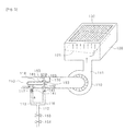
- FIGS. 5 and 6 An exemplary embodiment of a separate flow path type of gas-air mixing device according to an embodiment of the present invention will be described with reference to FIGS. 5 and 6 .
- a gas supply tube 112 of fuel gas is branched into a plurality of gas flow paths, for example, two gas flow paths 115 and 116, and an air supply tube 113 is branched into a plurality of air flow path, for example, two air flow paths 117 and 118.
- FIG. 6 schematically illustrates a case where the separate flow path type of gas-air mixing device according to the present invention is in a high-output mode.
- the air supply tube 113 is branched into the two air-path-flows 117 and 118 by, for example, air flow path branching apparatus 170.
- the air flow path branching apparatus 170 may be constituted by, for example, an "L"-shaped air flow path guide 171 and a "C"-shaped air flow path guide 172.
- a slot 173 is formed between the air flow path guide 171 and the air flow path guide 172, and the slot 173 serves as an air passage through which air in the air flow path 118 may pass.
- a joining part 174 which a rod 163 may pass through and be joined to, may be provided in the air flow path guide 172. Further, the rod 163 may even pass through the slot 173. To this end, the slot 173 and the joining part 174 are preferably formed at positions corresponding to each other.
- a pneumatic valve 153 for controlling a supply rate of gas in accordance with fire power of a burner required in a proportional control combustion system is connected to the gas supply tube 112, and a main valve 154 is connected to an inlet side of the gas supply tube of the pneumatic valve 153.
- the main valve 154 as an on/off valve serves to supply gas by opening and closing operations.
- the air and the gas that pass through the air supply tube 113 and the gas supply tube 112 become an air-gas mixture in a mixed-gas flow path 111 branched from the air supply tube 113, and then is supplied to a mixing chamber 120.
- a blower 110 for supplying air required in the air supply tube 113 is connected to a point where the air supply pipe 113 and the mixed-gas flow path 111 join.
- the gas supply tube 112 is connected to the air supply tube 113, while in the structure adopting the current proportional control valve as illustrated in FIG. 2 , the gas supply tube is directly connected to the mixing chamber 120.
- FIGS. 5 and 6 schematically illustrate a drive unit and the drive unit is configured to include a rod 163 that moves vertically upward and downwards by magnetic force of an electromagnet 165 and two valve bodies 161 and 162 attached to the rod 163.
- the gas supply flow rate is twice larger than when the gas supply is blocked in the gas flow path 116 by the valve body in FIG. 5 .
- the differential pressure ⁇ P is actually decreased due to the speed V b at point b of the air flow path 117 in FIG. 6 , the gas supply flow rate in FIG. 6 is not actually twice larger than the gas supply flow rate in FIG. 5 .
- a table below illustrates changes in gas supply rate depending on a change in speed of the blower in the low-output mode of FIG. 5 and the high-output mode of FIG. 6 , respectively based on an experimental result.
- Table 2 RPM of blower Low-output mode of FIG. 5 High-output mode of FIG. 6
- Q air V b ⁇ P Q gas Q air V b ⁇ P Q gas
- 1,000 10% 1 1 10% 18% 0.9 0.81 18% 2,000 20% 2 4 20% 36% 1.8 3.24 36% 3,000 30% 3 9 30% 54% 2.7 7.29 54% 4,000
- 4 16 40% 72% 3.6 12.96 72% 5,000 50% 5 25 50% 90% 4.5 20.25 90%
- Q air represents the air supply rate
- Q gas represents the gas supply rate
- the turn-down ratio may be approximately 9:1. That is, in order to acquire the turn-down ratio of 10:1, a blower in which the ratio of the maximum rpm and the minimum rpm ranges approximately from 6:1 to 7:1 needs to be used.
- nozzles 141 and 142 may be installed at outlet sides of the gas flow paths 115 and 116. Moreover, preferably, the nozzles 141 and 142 are installed in parallel on the gas flow paths 115 and 116.
- the mixture of the mixing chamber 120 is supplied to a burner surface 130.
- the combustion device including the separate flow path type of gas-air mixing device according to the present invention
- a controller may not be provided, which supplies only an amount of air required for combustion by controlling the rpm of the blower 10 depending on opening and closing the proportional control valve 33, unlike the gas boiler combustion device of FIG. 2 , and as a result, the combustion device may be simply configured, and since the air supply rate may already be decreased in the air supply tube 113 in the low-output mode, an excess air amount supplied to the burner is remarkably reduced, and as a result, efficiency deterioration by excess air is significantly reduced.
- a burner structure illustrated in FIGS. 5 and 6 includes the mixing chamber 120 to show a combustion structure of a pre-mixed burner.
- the pre-mixed burner pre-mixes the air and the gas to allow complete combustion and ejects the mixture to the burner surface 130 to achieve the combustion, and since the pre-mixed burner may perform combustion at a lower excess air ratio than a Bunsen burner, a dew-point temperature may be increased, and as a result, the pre-mixed burner is widely used particularly in the condensing boiler.
- nozzles 141 and 142 are exemplarily provided on the gas flow paths 115 and 116, respectively in the embodiment, two or more nozzles may be, of course, installed on the respective gas flow paths.
- a ratio in hole size of the nozzles 141 and 142 may be 5:5, but the hole sizes of the nozzles 141 and 142 may be different from each other like, for example, 4:6 in order to further increase the turn-down ratio (TDR).
- the mixing chamber 120 as a place where the air and the gas are mixed is connected to the mixed-gas flow path 111 as described above.
- an air distribution plate 121 is preferably installed in the mixing chamber 120 in order to smoothly mix the air and the gas by preventing the air and the gas from directly moving up to the burner surface 130.
- the existing used burner surface for pre-mixing may be used, for example, a metal fiber, ceramic, or a stainless perforated plate, or the like may be used.
- the combustion device of the gas-air mixing device according to the embodiment illustrated in FIGS. 5 and 6 has a problem in that the air flow path branching apparatus 170, which is branched into the two air flow paths 117 and 118, makes the flow of the air unnatural, and a width ⁇ D of the air flow path needs to be increased in order to reduce pressure loss caused by the unnatural air flow.
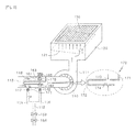
- any one gas flow path 215 of two gas flow paths 215 and 216 branched from a gas supply tube 212 extends to the inside of an air supply tube 213, preferably, to a boundary between two air flow paths 217 and 218 of the air supply tube 213.
- Opening and closing the gas flow path 215 is controlled by a drive unit constituted by a rod 263, which moves vertically up and down by magnetic force of an electromagnet 265, and one valve body 261 attached to the rod 263.
- the gas flow path 215 is connected to air flow path guides 271 and 272 that extend horizontally in parallel with the longitudinal direction of the air supply tube 213 such that the air flow path guides 271 and 272, and the gas supply tube 215 preferably have substantially a Y shape, in order to branch the air supply tube 213 into the two air flow paths 217 and 218.
- the valve body 261 may land on the air flow path guides 271 and 272.
- valve bodies 161 and 162 are used to open and close the air flow path 118 and the gas flow path 116, respectively, in the embodiment of FIGS. 5 and 6 , but in the embodiment of FIG. 7 , as seen at a part marked with a dotted line in 7(a), when the valve body 261 lands on the gas flow path 215, the gas flow path 215 and the air flow path 218 are simultaneously blocked to be switched to the low-output mode as illustrated in FIG. 5 .
- FIG. 7(b) which is a cross-sectional view cut in a direction vertical to the longitudinal direction of the air supply tube 213, openings are formed at the left and right sides of the gas supply tube 215 to allow air to pass through the other air flow path 217.
- a pneumatic valve 253, a main valve 254, and nozzles 241 and 242 of FIG. 7 correspond to the pneumatic valve 153, the main valve 154, and the nozzles 141 and 142 of FIGS. 5 and 6 , a description thereof will be omitted.
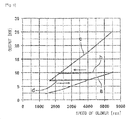
- a ratio of a maximum output and a minimum output that is, a turn-down ratio is 5:1 at C1 of FIG. 8 and a pressure differential in the maximum output is 200 mmH 2 O
- the pressure differential needs to be 8 mmH 2 O (that is, 200/5 2 ) in order to acquire an output which is 1/5 of the maximum output, that is, the minimum output.
- the output and the flow rate have a relationship to be proportional to the square root of the pressure differential.
- a minimum pressure differential needs to be decreased to 2 mmH 2 O (that is, 200/10 2 ) in order to increase the turn-down ratio to 10:1 while maintaining the maximum output at the same value.
- the combustion device since the combustion device needs to be generally used at the minimum 5 mmH 2 O or more in order to control the minimum gas amount, the value may not be practically permitted in a combustion control of the gas boiler.
- the separate flow path type of gas-air mixing device when any one gas flow path of the two gas flow paths 115 and 116, that is, the gas flow path 116 is closed by using the valve body 162, and simultaneously, the slot 173 is closed by using the valve body 161 (C2 of FIG. 8 ), the flow rates of both the gas and the air supplied to the mixing chamber 120 through the mixed-gas flow path 111 may be 55% of the flow rate in the maximum output. Therefore, a mixing ratio of the gas and the air is maintained constantly, but the minimum output may become 55% of the maximum output. As a result, the minimum output of approximately 11% of the maximum output may be achieved while maintaining the pressure differential of 8 mmH 2 O as in the output maximum.
- the turn-down ratio may be approximately 10:1 as illustrated in C of FIG. 8 by using the blower in which the ratio of the maximum rpm and the minimum rpm is 6:1.
- the blower in which the ratio of the maximum rpm and the minimum rpm is approximately 6:1, and not 5:1 needs to be used in order to acquire the turn-down ratio of 10:1 because the loss of the pressure differential occurs in the separate flow path type of gas-air mixing device according to the present invention due to the influence of the air supply tube 113 and the boiler structure, and the like.
- the output increases in the range of 2.5 kw to 10 kw while being substantially proportional to the speed of the blower in the low-output mode in which loads of heating and hot water are small (line a of FIG. 9 ) and the output increases in the range of 7 kw to 25 kw while being substantially proportional to the speed of the blower in the high-output mode in which the loads of the heating and hot water are large (line c of FIG. 9 ).
- the turn-down ratio is 10:1 (that is, 25:2.5).
- Line b of FIG. 9 indicates a case in which the low-output mode is switched to the high-output mode
- line d of FIG. 9 indicates a case in which the high-output mode is switched to the low-output mode.
- the combustion device including the separate flow path type of gas-air mixing device according to the present invention may be, of course, applied to even a water heater, and the like, in addition to the gas boiler.
Landscapes
- Engineering & Computer Science (AREA)
- Chemical & Material Sciences (AREA)
- Combustion & Propulsion (AREA)
- Mechanical Engineering (AREA)
- General Engineering & Computer Science (AREA)
- Chemical Kinetics & Catalysis (AREA)
- Regulation And Control Of Combustion (AREA)
- Gas Burners (AREA)
- Multiple-Way Valves (AREA)
- Accessories For Mixers (AREA)
Applications Claiming Priority (3)
| Application Number | Priority Date | Filing Date | Title |
|---|---|---|---|
| KR20110026776 | 2011-03-25 | ||
| KR1020110084417A KR101214745B1 (ko) | 2011-03-25 | 2011-08-24 | 유로 분리형 가스-공기 혼합장치 |
| EP11862540.9A EP2690361B1 (fr) | 2011-03-25 | 2011-12-20 | Type de chemin d'écoulement séparé de dispositif de mélange gaz-air |
Related Parent Applications (2)
| Application Number | Title | Priority Date | Filing Date |
|---|---|---|---|
| EP11862540.9A Division EP2690361B1 (fr) | 2011-03-25 | 2011-12-20 | Type de chemin d'écoulement séparé de dispositif de mélange gaz-air |
| EP11862540.9A Division-Into EP2690361B1 (fr) | 2011-03-25 | 2011-12-20 | Type de chemin d'écoulement séparé de dispositif de mélange gaz-air |
Publications (1)
| Publication Number | Publication Date |
|---|---|
| EP2955437A1 true EP2955437A1 (fr) | 2015-12-16 |
Family
ID=47281003
Family Applications (2)
| Application Number | Title | Priority Date | Filing Date |
|---|---|---|---|
| EP11862540.9A Active EP2690361B1 (fr) | 2011-03-25 | 2011-12-20 | Type de chemin d'écoulement séparé de dispositif de mélange gaz-air |
| EP15175134.4A Withdrawn EP2955437A1 (fr) | 2011-03-25 | 2011-12-20 | Type de trajet d'écoulement d'un dispositif à mélange air-gaz |
Family Applications Before (1)
| Application Number | Title | Priority Date | Filing Date |
|---|---|---|---|
| EP11862540.9A Active EP2690361B1 (fr) | 2011-03-25 | 2011-12-20 | Type de chemin d'écoulement séparé de dispositif de mélange gaz-air |
Country Status (10)
| Country | Link |
|---|---|
| US (1) | US9364799B2 (fr) |
| EP (2) | EP2690361B1 (fr) |
| JP (1) | JP5597775B2 (fr) |
| KR (1) | KR101214745B1 (fr) |
| CN (1) | CN103328889B (fr) |
| AU (2) | AU2011364585B2 (fr) |
| BR (1) | BR112013018907B1 (fr) |
| CA (2) | CA2824674C (fr) |
| CL (1) | CL2013002124A1 (fr) |
| WO (1) | WO2012134033A1 (fr) |
Families Citing this family (23)
| Publication number | Priority date | Publication date | Assignee | Title |
|---|---|---|---|---|
| KR100805630B1 (ko) * | 2006-12-01 | 2008-02-20 | 주식회사 경동나비엔 | 가스보일러의 연소장치 |
| KR101214745B1 (ko) * | 2011-03-25 | 2012-12-21 | 주식회사 경동나비엔 | 유로 분리형 가스-공기 혼합장치 |
| KR101308932B1 (ko) | 2012-02-06 | 2013-09-23 | 주식회사 경동나비엔 | 연소기기용 가스 공기 혼합장치 |
| KR101308936B1 (ko) | 2012-02-06 | 2013-09-23 | 주식회사 경동나비엔 | 연소기기용 가스 공기 혼합장치 |
| KR101319256B1 (ko) | 2012-03-05 | 2013-10-17 | 주식회사 경동나비엔 | 연소기기용 가스 공기 혼합장치 |
| KR101331426B1 (ko) | 2012-12-03 | 2013-11-21 | 주식회사 경동나비엔 | 연소기기용 듀얼 벤츄리 |
| KR101436867B1 (ko) * | 2012-12-28 | 2014-09-02 | 주식회사 경동나비엔 | 공기비례제어식 연소장치와 그 열량 조정방법 |
| US9464805B2 (en) * | 2013-01-16 | 2016-10-11 | Lochinvar, Llc | Modulating burner |
| US9574771B2 (en) | 2013-12-30 | 2017-02-21 | American Air Liquide, Inc. | Method and burner using the curie effect for controlling reactant velocity for operation in pre-heated and non-pre-heated modes |
| US10823400B2 (en) * | 2014-01-09 | 2020-11-03 | A.O. Smith Corporation | Multi-cavity gas and air mixing device |
| JP6189795B2 (ja) | 2014-06-04 | 2017-08-30 | リンナイ株式会社 | 予混合装置 |
| JP6050281B2 (ja) * | 2014-06-06 | 2016-12-21 | リンナイ株式会社 | 予混合装置 |
| CN107213810B (zh) * | 2016-03-22 | 2023-06-27 | 中国石油化工股份有限公司 | 氧气与可燃气体高效、安全混合的方法 |
| CN107213809B (zh) * | 2016-03-22 | 2023-06-02 | 中国石油化工股份有限公司 | 氧气与可燃气体旋流混合的方法 |
| US10330312B2 (en) * | 2016-03-28 | 2019-06-25 | Rinnai Corporation | Premixing apparatus |
| JP6725339B2 (ja) * | 2016-03-28 | 2020-07-15 | リンナイ株式会社 | 予混合装置 |
| JP6654494B2 (ja) * | 2016-04-01 | 2020-02-26 | リンナイ株式会社 | 予混合装置の制御方法 |
| US10274195B2 (en) * | 2016-08-31 | 2019-04-30 | Honeywell International Inc. | Air/gas admittance device for a combustion appliance |
| CN111947296B (zh) * | 2020-07-21 | 2022-04-05 | 华帝股份有限公司 | 一种全预混燃气热水器的控制方法 |
| CN111947315A (zh) * | 2020-08-12 | 2020-11-17 | 华帝股份有限公司 | 一种全预混燃气热水器及其控制方法 |
| DE102020132504A1 (de) * | 2020-12-07 | 2022-06-09 | Ebm-Papst Landshut Gmbh | Drosselanordnung |
| CN113154377B (zh) * | 2021-02-26 | 2023-05-12 | 无锡赛威特燃烧器制造有限公司 | 一种节能环保沼气专用燃烧器 |
| DE102023105827A1 (de) | 2023-03-09 | 2024-09-12 | Vaillant Gmbh | Verfahren zum Betrieb eines variablen Brenners, Brenner und Computerprogramm |
Citations (4)
| Publication number | Priority date | Publication date | Assignee | Title |
|---|---|---|---|---|
| US4602610A (en) * | 1981-01-30 | 1986-07-29 | Mcginnis George P | Dual-rate fuel flow control system for space heater |
| EP0275439A1 (fr) * | 1987-01-02 | 1988-07-27 | Karl Dungs GmbH & Co. | Dispositif de régulation de puissance de générateurs de chaleur à carburant |
| KR100805630B1 (ko) | 2006-12-01 | 2008-02-20 | 주식회사 경동나비엔 | 가스보일러의 연소장치 |
| WO2009133451A2 (fr) * | 2008-04-30 | 2009-11-05 | Gas Point S.R.L. | Brûleur à gaz à prémélange |
Family Cites Families (26)
| Publication number | Priority date | Publication date | Assignee | Title |
|---|---|---|---|---|
| US1684500A (en) * | 1924-02-02 | 1928-09-18 | Garnet W Mckee | Apparatus for proportionately mixing fluids |
| US1664318A (en) * | 1925-04-15 | 1928-03-27 | John M Hopwood | Fuel-supply system |
| US2731036A (en) * | 1951-10-06 | 1956-01-17 | Reynolds Gas Regulator Company | Valve seat structure |
| GB783699A (en) * | 1953-11-11 | 1957-09-25 | Perl Controls Ltd | Improvements in and relating to automatic gas valves |
| US3012583A (en) * | 1960-07-25 | 1961-12-12 | Manning Maxwell & Moore Inc | Double-seated valve for high temperature work |
| US4417868A (en) * | 1981-09-04 | 1983-11-29 | Battelle Development Corporation | Compact plenum for pulse combustors |
| WO1988009463A1 (fr) * | 1987-05-28 | 1988-12-01 | Eiken Kougyo Kabushiki Kaisha | Soupape de commande du rapport gaz-air pour bruleurs a gaz |
| JPH0350413A (ja) * | 1989-07-14 | 1991-03-05 | Rinnai Corp | 燃焼器の制御装置 |
| DE4019073A1 (de) * | 1990-06-15 | 1991-12-19 | Rexroth Pneumatik Mannesmann | Ventileinrichtung |
| JP2622476B2 (ja) | 1992-09-11 | 1997-06-18 | リンナイ株式会社 | 低窒素酸化物バーナ |
| AU666034B2 (en) | 1992-09-11 | 1996-01-25 | Rinnai Kabushiki Kaisha | A porous gas burner for a water heater and a method of making thereof |
| JP2622475B2 (ja) * | 1992-09-11 | 1997-06-18 | リンナイ株式会社 | 低窒素酸化物バーナ |
| JP2587095Y2 (ja) * | 1992-10-14 | 1998-12-14 | 株式会社ガスター | 希薄燃焼用バーナ |
| JP3300661B2 (ja) | 1998-01-28 | 2002-07-08 | リンナイ株式会社 | ノズルマニホールド |
| US5993195A (en) * | 1998-03-27 | 1999-11-30 | Carrier Corporation | Combustion air regulating apparatus for use with induced draft furnaces |
| DE19925567C1 (de) * | 1999-06-04 | 2000-12-14 | Honeywell Bv | Vorrichtung für Gasbrenner |
| JP2001099410A (ja) * | 1999-07-27 | 2001-04-13 | Osaka Gas Co Ltd | 燃焼装置 |
| KR100371208B1 (ko) | 2000-06-16 | 2003-02-06 | 한국에너지기술연구원 | 예혼합식 파이버매트 촉매버너 |
| JP2002005435A (ja) * | 2000-06-23 | 2002-01-09 | Harman Co Ltd | 全一次式燃焼バーナの燃焼制御装置 |
| JP2002177751A (ja) * | 2000-12-14 | 2002-06-25 | Tokyo Gas Co Ltd | 混合器及び該混合器を備えたガスバーナ |
| US6537060B2 (en) | 2001-03-09 | 2003-03-25 | Honeywell International Inc. | Regulating system for gas burners |
| KR100681386B1 (ko) * | 2005-01-12 | 2007-02-09 | 주식회사 경동네트웍 | 공연비감지센서를 이용한 연소장치 |
| KR100808318B1 (ko) * | 2007-01-19 | 2008-02-27 | 주식회사 경동나비엔 | 가스보일러용 버너 |
| CN201281332Y (zh) * | 2008-05-28 | 2009-07-29 | 胡占胜 | 节能燃烧器 |
| US20100330520A1 (en) * | 2009-06-29 | 2010-12-30 | Noritz Corporation | Combustion apparatus |
| KR101214745B1 (ko) * | 2011-03-25 | 2012-12-21 | 주식회사 경동나비엔 | 유로 분리형 가스-공기 혼합장치 |
-
2011
- 2011-08-24 KR KR1020110084417A patent/KR101214745B1/ko active Active
- 2011-12-20 EP EP11862540.9A patent/EP2690361B1/fr active Active
- 2011-12-20 CA CA2824674A patent/CA2824674C/fr active Active
- 2011-12-20 WO PCT/KR2011/009888 patent/WO2012134033A1/fr not_active Ceased
- 2011-12-20 EP EP15175134.4A patent/EP2955437A1/fr not_active Withdrawn
- 2011-12-20 US US13/979,082 patent/US9364799B2/en active Active
- 2011-12-20 CA CA2896605A patent/CA2896605C/fr active Active
- 2011-12-20 CN CN201180065947.5A patent/CN103328889B/zh active Active
- 2011-12-20 AU AU2011364585A patent/AU2011364585B2/en active Active
- 2011-12-20 BR BR112013018907-0A patent/BR112013018907B1/pt active IP Right Grant
- 2011-12-20 JP JP2013549356A patent/JP5597775B2/ja not_active Expired - Fee Related
-
2013
- 2013-07-24 CL CL2013002124A patent/CL2013002124A1/es unknown
-
2015
- 2015-08-10 AU AU2015210482A patent/AU2015210482B2/en active Active
Patent Citations (4)
| Publication number | Priority date | Publication date | Assignee | Title |
|---|---|---|---|---|
| US4602610A (en) * | 1981-01-30 | 1986-07-29 | Mcginnis George P | Dual-rate fuel flow control system for space heater |
| EP0275439A1 (fr) * | 1987-01-02 | 1988-07-27 | Karl Dungs GmbH & Co. | Dispositif de régulation de puissance de générateurs de chaleur à carburant |
| KR100805630B1 (ko) | 2006-12-01 | 2008-02-20 | 주식회사 경동나비엔 | 가스보일러의 연소장치 |
| WO2009133451A2 (fr) * | 2008-04-30 | 2009-11-05 | Gas Point S.R.L. | Brûleur à gaz à prémélange |
Also Published As
| Publication number | Publication date |
|---|---|
| JP5597775B2 (ja) | 2014-10-01 |
| US9364799B2 (en) | 2016-06-14 |
| CL2013002124A1 (es) | 2014-01-17 |
| BR112013018907B1 (pt) | 2021-01-26 |
| US20130294192A1 (en) | 2013-11-07 |
| EP2690361A4 (fr) | 2014-12-24 |
| AU2015210482B2 (en) | 2017-06-01 |
| CN103328889A (zh) | 2013-09-25 |
| BR112013018907A2 (pt) | 2016-10-04 |
| JP2014502719A (ja) | 2014-02-03 |
| CA2824674A1 (fr) | 2012-10-04 |
| EP2690361A1 (fr) | 2014-01-29 |
| AU2015210482A1 (en) | 2015-09-03 |
| CA2896605A1 (fr) | 2012-10-04 |
| KR101214745B1 (ko) | 2012-12-21 |
| KR20120109966A (ko) | 2012-10-09 |
| AU2011364585B2 (en) | 2015-08-27 |
| CA2824674C (fr) | 2015-11-24 |
| WO2012134033A1 (fr) | 2012-10-04 |
| EP2690361B1 (fr) | 2019-05-22 |
| CA2896605C (fr) | 2017-05-16 |
| CN103328889B (zh) | 2015-05-20 |
Similar Documents
| Publication | Publication Date | Title |
|---|---|---|
| EP2955437A1 (fr) | Type de trajet d'écoulement d'un dispositif à mélange air-gaz | |
| US20100047728A1 (en) | Combustion apparatus for a gas boiler | |
| US9970654B2 (en) | Combustion device for improving turndown ratio | |
| US9777919B2 (en) | Combustion apparatus | |
| JP5948440B2 (ja) | 燃焼機器用ガス‐空気混合装置 | |
| KR101733061B1 (ko) | Tdr 댐퍼 | |
| JP3993023B2 (ja) | 熱風循環装置 | |
| JP2002081618A (ja) | 燃焼装置及びそれを備えた流体加熱装置 | |
| JP5903828B2 (ja) | 熱媒ボイラ | |
| JP2006145088A (ja) | 濃淡燃焼バーナおよびこれを用いた燃焼装置 | |
| JP2007107865A (ja) | 燃焼装置 |
Legal Events
| Date | Code | Title | Description |
|---|---|---|---|
| PUAI | Public reference made under article 153(3) epc to a published international application that has entered the european phase |
Free format text: ORIGINAL CODE: 0009012 |
|
| AC | Divisional application: reference to earlier application |
Ref document number: 2690361 Country of ref document: EP Kind code of ref document: P |
|
| AK | Designated contracting states |
Kind code of ref document: A1 Designated state(s): AL AT BE BG CH CY CZ DE DK EE ES FI FR GB GR HR HU IE IS IT LI LT LU LV MC MK MT NL NO PL PT RO RS SE SI SK SM TR |
|
| 17P | Request for examination filed |
Effective date: 20160331 |
|
| RBV | Designated contracting states (corrected) |
Designated state(s): AL AT BE BG CH CY CZ DE DK EE ES FI FR GB GR HR HU IE IS IT LI LT LU LV MC MK MT NL NO PL PT RO RS SE SI SK SM TR |
|
| STAA | Information on the status of an ep patent application or granted ep patent |
Free format text: STATUS: EXAMINATION IS IN PROGRESS |
|
| 17Q | First examination report despatched |
Effective date: 20200124 |
|
| GRAP | Despatch of communication of intention to grant a patent |
Free format text: ORIGINAL CODE: EPIDOSNIGR1 |
|
| STAA | Information on the status of an ep patent application or granted ep patent |
Free format text: STATUS: GRANT OF PATENT IS INTENDED |
|
| INTG | Intention to grant announced |
Effective date: 20210210 |
|
| STAA | Information on the status of an ep patent application or granted ep patent |
Free format text: STATUS: THE APPLICATION IS DEEMED TO BE WITHDRAWN |
|
| 18D | Application deemed to be withdrawn |
Effective date: 20210622 |