EP2955455B1 - Dispositif d'entraînement par moteur et climatiseur comprenant celui-ci - Google Patents
Dispositif d'entraînement par moteur et climatiseur comprenant celui-ci Download PDFInfo
- Publication number
- EP2955455B1 EP2955455B1 EP15171042.3A EP15171042A EP2955455B1 EP 2955455 B1 EP2955455 B1 EP 2955455B1 EP 15171042 A EP15171042 A EP 15171042A EP 2955455 B1 EP2955455 B1 EP 2955455B1
- Authority
- EP
- European Patent Office
- Prior art keywords
- voltage
- driving device
- capacitor
- motor driving
- input
- Prior art date
- Legal status (The legal status is an assumption and is not a legal conclusion. Google has not performed a legal analysis and makes no representation as to the accuracy of the status listed.)
- Active
Links
Images






Classifications
-
- H—ELECTRICITY
- H02—GENERATION; CONVERSION OR DISTRIBUTION OF ELECTRIC POWER
- H02P—CONTROL OR REGULATION OF ELECTRIC MOTORS, ELECTRIC GENERATORS OR DYNAMO-ELECTRIC CONVERTERS; CONTROLLING TRANSFORMERS, REACTORS OR CHOKE COILS
- H02P5/00—Arrangements specially adapted for regulating or controlling the speed or torque of two or more electric motors
- H02P5/74—Arrangements specially adapted for regulating or controlling the speed or torque of two or more electric motors controlling two or more AC dynamo-electric motors
-
- F—MECHANICAL ENGINEERING; LIGHTING; HEATING; WEAPONS; BLASTING
- F24—HEATING; RANGES; VENTILATING
- F24F—AIR-CONDITIONING; AIR-HUMIDIFICATION; VENTILATION; USE OF AIR CURRENTS FOR SCREENING
- F24F11/00—Control or safety arrangements
- F24F11/30—Control or safety arrangements for purposes related to the operation of the system, e.g. for safety or monitoring
-
- F—MECHANICAL ENGINEERING; LIGHTING; HEATING; WEAPONS; BLASTING
- F24—HEATING; RANGES; VENTILATING
- F24F—AIR-CONDITIONING; AIR-HUMIDIFICATION; VENTILATION; USE OF AIR CURRENTS FOR SCREENING
- F24F11/00—Control or safety arrangements
- F24F11/30—Control or safety arrangements for purposes related to the operation of the system, e.g. for safety or monitoring
- F24F11/32—Responding to malfunctions or emergencies
-
- F—MECHANICAL ENGINEERING; LIGHTING; HEATING; WEAPONS; BLASTING
- F24—HEATING; RANGES; VENTILATING
- F24F—AIR-CONDITIONING; AIR-HUMIDIFICATION; VENTILATION; USE OF AIR CURRENTS FOR SCREENING
- F24F11/00—Control or safety arrangements
- F24F11/70—Control systems characterised by their outputs; Constructional details thereof
- F24F11/72—Control systems characterised by their outputs; Constructional details thereof for controlling the supply of treated air, e.g. its pressure
- F24F11/74—Control systems characterised by their outputs; Constructional details thereof for controlling the supply of treated air, e.g. its pressure for controlling air flow rate or air velocity
- F24F11/77—Control systems characterised by their outputs; Constructional details thereof for controlling the supply of treated air, e.g. its pressure for controlling air flow rate or air velocity by controlling the speed of ventilators
-
- F—MECHANICAL ENGINEERING; LIGHTING; HEATING; WEAPONS; BLASTING
- F25—REFRIGERATION OR COOLING; COMBINED HEATING AND REFRIGERATION SYSTEMS; HEAT PUMP SYSTEMS; MANUFACTURE OR STORAGE OF ICE; LIQUEFACTION SOLIDIFICATION OF GASES
- F25B—REFRIGERATION MACHINES, PLANTS OR SYSTEMS; COMBINED HEATING AND REFRIGERATION SYSTEMS; HEAT PUMP SYSTEMS
- F25B13/00—Compression machines, plants or systems, with reversible cycle
-
- F—MECHANICAL ENGINEERING; LIGHTING; HEATING; WEAPONS; BLASTING
- F25—REFRIGERATION OR COOLING; COMBINED HEATING AND REFRIGERATION SYSTEMS; HEAT PUMP SYSTEMS; MANUFACTURE OR STORAGE OF ICE; LIQUEFACTION SOLIDIFICATION OF GASES
- F25B—REFRIGERATION MACHINES, PLANTS OR SYSTEMS; COMBINED HEATING AND REFRIGERATION SYSTEMS; HEAT PUMP SYSTEMS
- F25B31/00—Compressor arrangements
- F25B31/02—Compressor arrangements of motor-compressor units
-
- F—MECHANICAL ENGINEERING; LIGHTING; HEATING; WEAPONS; BLASTING
- F25—REFRIGERATION OR COOLING; COMBINED HEATING AND REFRIGERATION SYSTEMS; HEAT PUMP SYSTEMS; MANUFACTURE OR STORAGE OF ICE; LIQUEFACTION SOLIDIFICATION OF GASES
- F25B—REFRIGERATION MACHINES, PLANTS OR SYSTEMS; COMBINED HEATING AND REFRIGERATION SYSTEMS; HEAT PUMP SYSTEMS
- F25B49/00—Arrangement or mounting of control or safety devices
- F25B49/02—Arrangement or mounting of control or safety devices for compression type machines, plants or systems
- F25B49/025—Motor control arrangements
-
- H—ELECTRICITY
- H02—GENERATION; CONVERSION OR DISTRIBUTION OF ELECTRIC POWER
- H02M—APPARATUS FOR CONVERSION BETWEEN AC AND AC, BETWEEN AC AND DC, OR BETWEEN DC AND DC, AND FOR USE WITH MAINS OR SIMILAR POWER SUPPLY SYSTEMS; CONVERSION OF DC OR AC INPUT POWER INTO SURGE OUTPUT POWER; CONTROL OR REGULATION THEREOF
- H02M1/00—Details of apparatus for conversion
- H02M1/42—Circuits or arrangements for compensating for or adjusting power factor in converters or inverters
- H02M1/4208—Arrangements for improving power factor of AC input
- H02M1/4225—Arrangements for improving power factor of AC input using a non-isolated boost converter
-
- H—ELECTRICITY
- H02—GENERATION; CONVERSION OR DISTRIBUTION OF ELECTRIC POWER
- H02P—CONTROL OR REGULATION OF ELECTRIC MOTORS, ELECTRIC GENERATORS OR DYNAMO-ELECTRIC CONVERTERS; CONTROLLING TRANSFORMERS, REACTORS OR CHOKE COILS
- H02P27/00—Arrangements or methods for the control of AC motors characterised by the kind of supply voltage
- H02P27/04—Arrangements or methods for the control of AC motors characterised by the kind of supply voltage using variable-frequency supply voltage, e.g. inverter or converter supply voltage
- H02P27/06—Arrangements or methods for the control of AC motors characterised by the kind of supply voltage using variable-frequency supply voltage, e.g. inverter or converter supply voltage using DC to AC converters or inverters
-
- F—MECHANICAL ENGINEERING; LIGHTING; HEATING; WEAPONS; BLASTING
- F25—REFRIGERATION OR COOLING; COMBINED HEATING AND REFRIGERATION SYSTEMS; HEAT PUMP SYSTEMS; MANUFACTURE OR STORAGE OF ICE; LIQUEFACTION SOLIDIFICATION OF GASES
- F25B—REFRIGERATION MACHINES, PLANTS OR SYSTEMS; COMBINED HEATING AND REFRIGERATION SYSTEMS; HEAT PUMP SYSTEMS
- F25B2313/00—Compression machines, plants or systems with reversible cycle not otherwise provided for
- F25B2313/005—Outdoor unit expansion valves
-
- F—MECHANICAL ENGINEERING; LIGHTING; HEATING; WEAPONS; BLASTING
- F25—REFRIGERATION OR COOLING; COMBINED HEATING AND REFRIGERATION SYSTEMS; HEAT PUMP SYSTEMS; MANUFACTURE OR STORAGE OF ICE; LIQUEFACTION SOLIDIFICATION OF GASES
- F25B—REFRIGERATION MACHINES, PLANTS OR SYSTEMS; COMBINED HEATING AND REFRIGERATION SYSTEMS; HEAT PUMP SYSTEMS
- F25B2313/00—Compression machines, plants or systems with reversible cycle not otherwise provided for
- F25B2313/006—Compression machines, plants or systems with reversible cycle not otherwise provided for two pipes connecting the outdoor side to the indoor side with multiple indoor units
-
- F—MECHANICAL ENGINEERING; LIGHTING; HEATING; WEAPONS; BLASTING
- F25—REFRIGERATION OR COOLING; COMBINED HEATING AND REFRIGERATION SYSTEMS; HEAT PUMP SYSTEMS; MANUFACTURE OR STORAGE OF ICE; LIQUEFACTION SOLIDIFICATION OF GASES
- F25B—REFRIGERATION MACHINES, PLANTS OR SYSTEMS; COMBINED HEATING AND REFRIGERATION SYSTEMS; HEAT PUMP SYSTEMS
- F25B2313/00—Compression machines, plants or systems with reversible cycle not otherwise provided for
- F25B2313/027—Compression machines, plants or systems with reversible cycle not otherwise provided for characterised by the reversing means
- F25B2313/02741—Compression machines, plants or systems with reversible cycle not otherwise provided for characterised by the reversing means using one four-way valve
-
- F—MECHANICAL ENGINEERING; LIGHTING; HEATING; WEAPONS; BLASTING
- F25—REFRIGERATION OR COOLING; COMBINED HEATING AND REFRIGERATION SYSTEMS; HEAT PUMP SYSTEMS; MANUFACTURE OR STORAGE OF ICE; LIQUEFACTION SOLIDIFICATION OF GASES
- F25B—REFRIGERATION MACHINES, PLANTS OR SYSTEMS; COMBINED HEATING AND REFRIGERATION SYSTEMS; HEAT PUMP SYSTEMS
- F25B2600/00—Control issues
- F25B2600/02—Compressor control
- F25B2600/021—Inverters therefor
-
- F—MECHANICAL ENGINEERING; LIGHTING; HEATING; WEAPONS; BLASTING
- F25—REFRIGERATION OR COOLING; COMBINED HEATING AND REFRIGERATION SYSTEMS; HEAT PUMP SYSTEMS; MANUFACTURE OR STORAGE OF ICE; LIQUEFACTION SOLIDIFICATION OF GASES
- F25B—REFRIGERATION MACHINES, PLANTS OR SYSTEMS; COMBINED HEATING AND REFRIGERATION SYSTEMS; HEAT PUMP SYSTEMS
- F25B2700/00—Sensing or detecting of parameters; Sensors therefor
- F25B2700/15—Power, e.g. by voltage or current
- F25B2700/151—Power, e.g. by voltage or current of the compressor motor
-
- H—ELECTRICITY
- H02—GENERATION; CONVERSION OR DISTRIBUTION OF ELECTRIC POWER
- H02M—APPARATUS FOR CONVERSION BETWEEN AC AND AC, BETWEEN AC AND DC, OR BETWEEN DC AND DC, AND FOR USE WITH MAINS OR SIMILAR POWER SUPPLY SYSTEMS; CONVERSION OF DC OR AC INPUT POWER INTO SURGE OUTPUT POWER; CONTROL OR REGULATION THEREOF
- H02M1/00—Details of apparatus for conversion
- H02M1/0067—Converter structures employing plural converter units, other than for parallel operation of the units on a single load
- H02M1/007—Plural converter units in cascade
-
- H—ELECTRICITY
- H02—GENERATION; CONVERSION OR DISTRIBUTION OF ELECTRIC POWER
- H02M—APPARATUS FOR CONVERSION BETWEEN AC AND AC, BETWEEN AC AND DC, OR BETWEEN DC AND DC, AND FOR USE WITH MAINS OR SIMILAR POWER SUPPLY SYSTEMS; CONVERSION OF DC OR AC INPUT POWER INTO SURGE OUTPUT POWER; CONTROL OR REGULATION THEREOF
- H02M1/00—Details of apparatus for conversion
- H02M1/0067—Converter structures employing plural converter units, other than for parallel operation of the units on a single load
- H02M1/008—Plural converter units for generating at two or more independent and non-parallel outputs, e.g. systems with plural point of load switching regulators
-
- Y—GENERAL TAGGING OF NEW TECHNOLOGICAL DEVELOPMENTS; GENERAL TAGGING OF CROSS-SECTIONAL TECHNOLOGIES SPANNING OVER SEVERAL SECTIONS OF THE IPC; TECHNICAL SUBJECTS COVERED BY FORMER USPC CROSS-REFERENCE ART COLLECTIONS [XRACs] AND DIGESTS
- Y02—TECHNOLOGIES OR APPLICATIONS FOR MITIGATION OR ADAPTATION AGAINST CLIMATE CHANGE
- Y02B—CLIMATE CHANGE MITIGATION TECHNOLOGIES RELATED TO BUILDINGS, e.g. HOUSING, HOUSE APPLIANCES OR RELATED END-USER APPLICATIONS
- Y02B30/00—Energy efficient heating, ventilation or air conditioning [HVAC]
- Y02B30/70—Efficient control or regulation technologies, e.g. for control of refrigerant flow, motor or heating
-
- Y—GENERAL TAGGING OF NEW TECHNOLOGICAL DEVELOPMENTS; GENERAL TAGGING OF CROSS-SECTIONAL TECHNOLOGIES SPANNING OVER SEVERAL SECTIONS OF THE IPC; TECHNICAL SUBJECTS COVERED BY FORMER USPC CROSS-REFERENCE ART COLLECTIONS [XRACs] AND DIGESTS
- Y02—TECHNOLOGIES OR APPLICATIONS FOR MITIGATION OR ADAPTATION AGAINST CLIMATE CHANGE
- Y02B—CLIMATE CHANGE MITIGATION TECHNOLOGIES RELATED TO BUILDINGS, e.g. HOUSING, HOUSE APPLIANCES OR RELATED END-USER APPLICATIONS
- Y02B70/00—Technologies for an efficient end-user side electric power management and consumption
- Y02B70/10—Technologies improving the efficiency by using switched-mode power supplies [SMPS], i.e. efficient power electronics conversion e.g. power factor correction or reduction of losses in power supplies or efficient standby modes
Definitions
- the present invention relates to a motor driving device and an air conditioner including the same, and more particularly to a motor driving device capable of driving both a compressor motor and a fan motor, using the same input AC power under the condition that the motor driving devices employs a low-capacitance capacitor and an air conditioner including the same.
- An air conditioner is installed to provide a pleasant indoor environment to persons by adjusting indoor temperature and conditioning indoor air through discharge of hot or cold air into an indoor space.
- an air conditioner includes an indoor unit installed in an indoor space while including a heat exchanger, and an outdoor unit including a compressor and a heat exchanger, to supply refrigerant to the indoor unit.
- Patent document US-6397611-B discloses a motor driving device according to the preamble of claim 1.
- a motor driving device including a rectifier to rectify input AC power, a boost converter to boost the rectified power from the rectifier, and to output the boosted power, a first capacitor to store a pulsating voltage from the boost converter, a first inverter including a plurality of switching elements, the first inverter outputting, to a compressor motor, AC power transformed using a voltage across the first capacitor, a second capacitor to store the rectified power from the rectifier, a second inverter including a plurality of switching elements, the second inverter outputting, to a first fan motor, AC power transformed using a voltage across the second capacitor, and a voltage dropper to drop the voltage across the second capacitor, and to output the dropped voltage.
- an air conditioner including a compressor for compressing a refrigerant, a heat exchanger for performing heat exchange, using the compressed refrigerant, and a compressor motor driving device for driving a motor equipped in the compressor, wherein the compressor motor driving device includes a rectifier to rectify input AC power, a boost converter to boost the rectified power from the rectifier, and to output the boosted power, a first capacitor to store a pulsating voltage from the boost converter, a first inverter including a plurality of switching elements, the first inverter outputting, to a compressor motor, AC power transformed using a voltage across the first capacitor, a second capacitor to store the rectified power from the rectifier, a second inverter including a plurality of switching elements, the second inverter outputting, to a first fan motor, AC power transformed using a voltage across the second capacitor, and a voltage dropper to drop the voltage across the second capacitor, and to output the dropped voltage.
- the compressor motor driving device includes a rectifier to rectify input AC power, a boost
- module or "unit” is suffixed to constituent elements described in the following description, this is intended only for ease of description of the specification.
- the suffixes themselves have no meaning or function to distinguish the constituent element using the suffix from the constituent element using no suffix.
- the suffixes “module” and “unit” may be used interchangeably.
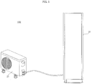
- FIG. 1 is a view illustrating a configuration of an air conditioner according to an embodiment of the present invention.
- the air conditioner which is designated by reference numeral "100" may include an indoor unit 31, and an outdoor unit connected to the indoor unit 31.
- the indoor unit 31 may be applied to any one of a stand type air conditioner, a wall-mounted air conditioner and a ceiling-mounted air conditioner is applicable. For convenience of description, however, the following description will be given only in conjunction with a stand type indoor unit.
- the air conditioner 100 may further include at least one of a ventilator, an air cleaner, a humidifier, and a heater. These devices may be operatively connected to the indoor unit and outdoor unit.
- the outdoor unit 21 includes a compressor (not shown) for compressing refrigerant supplied thereto, an outdoor heat exchanger (not shown) for exchanging heat between refrigerant and outdoor air, an accumulator (not shown) for separating gaseous refrigerant from refrigerant supplied thereto, and supplying the separated gaseous refrigerant to the compressor, and a 4-way valve (not shown) for selecting a flow path of refrigerant according to heating operation.
- the outdoor unit further includes a plurality of sensors, a plurality of valves, and an oil collector, etc., no description will be given of configurations of these elements.
- the outdoor unit 21 operates the compressor and outdoor heat exchanger included therein, to perform compression and heat exchange of refrigerant, and supplies the resultant refrigerant to the indoor unit.
- the outdoor unit 21 is driven in accordance with a demand from the remote control unit (not shown) or the indoor unit 31.
- the air conditioner 100 may include a plurality of indoor units, and a plurality of outdoor units each connected to associated ones of the indoor units.
- the number of operating outdoor units and the number of operating compressors included in the operating outdoor units are varied as the cooling/heating capacity of the air conditioner is varied in accordance with the number of operating indoor units.
- the outdoor unit 21 supplies compressed refrigerant to the indoor unit 31 connected thereto.
- the indoor unit 31 receives refrigerant from the outdoor unit 21, and discharges cold or hot air to an indoor space.
- the indoor unit 31 includes an indoor heat exchanger (not shown), an indoor fan (not shown), an expansion valve (not shown) to expand refrigerant supplied thereto, and a plurality of sensors (not shown).
- the outdoor unit 21 and indoor unit 31 are connected by a communication line and, as such, receive and transmit data therebetween.
- the outdoor unit 21 and indoor unit 31 are connected to a remote control unit (not shown) in a wired or wireless manner and, as such, operate under control of the remote control unit (not shown).
- a remote controller (not shown) is connected to the indoor unit 31 and, as such, may input a control command from the user to the indoor unit 31, and may receive state information from the indoor unit 31, to display the received state information.
- the remote controller communicates with the indoor unit 31 in a wired or wireless manner in accordance with the connection type thereof.
- FIG. 2 is a schematic view of the outdoor unit and indoor unit illustrated in FIG. 1 .
- the air conditioner 100 mainly includes an indoor unit, for example, the indoor unit 31, and an outdoor unit, for example, the outdoor unit 21.
- the outdoor unit 21 includes a compressor 102 functioning to compress refrigerant, a compressor motor 102b to drive the compressor 102, an outdoor heat exchanger 104 functioning to discharge heat from the compressed refrigerant, and an outdoor blowing unit 105 including an outdoor fan 105a disposed at one side of the outdoor heat exchanger 104, to promote heat discharge of refrigerant, and a motor 105b to rotate the outdoor fan 105a.
- the outdoor unit 21 further includes an expansion device 106 to expand concentrated refrigerant, a cooling/heating switching valve 110 to change a flow path of compressed refrigerant, and an accumulator 103 to temporarily store gasified refrigerant, and then to supply the stored refrigerant to the compressor at a constant pressure after removing moisture and foreign matter from the refrigerant.
- an expansion device 106 to expand concentrated refrigerant
- a cooling/heating switching valve 110 to change a flow path of compressed refrigerant
- an accumulator 103 to temporarily store gasified refrigerant, and then to supply the stored refrigerant to the compressor at a constant pressure after removing moisture and foreign matter from the refrigerant.
- the indoor unit 31 includes an indoor heat exchanger 108 disposed in an indoor space, to perform a cooling/heating function, and an indoor blowing unit 109 including an indoor fan 109a disposed at one side of the indoor heat exchanger 108, to promote heat discharge of refrigerant, and a motor 109b to rotate the indoor fan 109a.
- the indoor unit 31 may include at least one indoor heat exchanger 108.
- As the compressor 102 at least one of an inverter compressor and a constant speed compressor may be used.
- the air conditioner 50 may be configured as a cooler to cool an indoor space.
- the air conditioner 50 may be configured as a heat pump to cool or heat an indoor space.
- the compressor 102 included in the outdoor unit 21 of FIG. 1 may be driven by a motor driving device 200 ( FIG. 3 ) to drive a compressor motor 250 ( FIG. 3 ).
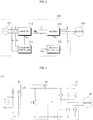
- FIG. 3 is a block diagram illustrating a motor driving device included in the outdoor unit of FIG. 1 .
- FIG. 4 is a circuit diagram illustrating the motor driving device of FIG. 3 .
- the motor driving device 200 may include an inverter 220 to output 3-phase AC current to the compressor motor 250, an inverter controller 230 to control the inverter 220, and a converter 210 to supply DC power to the inverter 220.
- the compressor motor driving device 200 may further include a converter controller 215 to control the converter 210, and a DC link capacitor C arranged between the converter 210 and the inverter 220.
- the motor driving device 200 may further include a DC link voltage detector B, an input voltage detector A, an input current detector D, and an output current detector E.
- the motor driving device 200 receives AC power from a power supply system, converts the received power, and then supplies the converted power to the compressor motor 250.
- the motor driving device 200 may be referred to as a "power converting device”.
- the DC link capacitor employed in the motor driving device 200 has a low capacitance of several tens of ⁇ F or less.
- the low-capacitance DC link capacitor C may include a film capacitor rather than an electrolytic capacitor.
- DC link voltage is pulsated due to increased variation thereof and, as such, little or no smoothing operation of the DC link capacitor is achieved.
- the motor driving device which includes a DC link capacitor having a low capacitance of several tens of ⁇ F or less, as described above, may be referred to as a "capacitorless motor driving device".
- the motor driving device 200 which includes the low-capacitance DC link capacitor C.
- the converter 210 converts input AC power into DC power.
- the converter 210 may include a rectifier 410 and a boost converter 420.
- the rectifier 410 rectifies single-phase AC power 201 input thereto, and outputs the rectified power.
- the rectifier 410 has a configuration in which two pairs of arm switching elements are connected in parallel, and each arm switching element pair includes an upper arm switching element and a lower arm switching element, which are connected in series, such that the arm switching elements are connected in a bridged manner.
- the boost converter 420 may include an inductor L1 and a diode D1, which are connected in series between the rectifier 410 and the inverter 220.
- the boost converter 420 may further include a switching element S1 connected between the inductor L1 and the diode D1. When the switching element S1 turns on, energy is stored in the inductor L1. When the switching element S1 turns off, the energy stored in the inductor L1 may be output via the diode D1.
- a voltage boosted to a certain level may be output from the boost converter 420.
- the converter controller 215 may control turning-on timing of the switching element S1 in the boost converter 420. For this function, the converter controller 215 may output a converter switching control signal Scc for turning-on timing of the switching element S1.
- the converter controller 215 may receive an input voltage Vs from the input voltage detector A and an input current Is from the input current detector B.
- the input voltage detector A may detect an input voltage Vs from the input AC power 201.
- the input voltage detector A may be arranged upstream of the rectifier 410.
- the input voltage detector A may include a resistor, an operational amplifier (OP AMP), etc.
- the detected input voltage Vs may be a pulse type discrete signal.
- the detected input voltage Vs may be applied to the converter controller 215, for generation of the converter switching control signal Scc.
- a zero crossing point of the input voltage may also be detected by the input voltage detector A.
- the input current detector D may detect an input voltage Is from the input AC power 201.
- the input current detector D may be arranged upstream of the rectifier 410.
- the input current detector D may include a current sensor, a current transformer (CT), a shunt resistor, etc.
- the detected input current Is may be a pulse type discrete signal.
- the detected input current Is may be applied to the converter controller 215, for generation of the converter switching control signal Scc.
- the DC voltage detector B may detect a pulsating voltage Vdc across the DC link capacitor C.
- the DC voltage detector B may include a resistor, an operational amplifier (OP AMP), etc.
- the detected voltage Vdc across the DC link capacitor C may be a pulse type discrete signal.
- the detected voltage Vdc may be applied to the inverter controller 230.
- An inverter switching control signal Sic may be generated, based on the DC voltage Vdc across the DC link capacitor C.
- the detected DC link voltage Vdc may be applied to the converter controller 215, for generation of the converter switching control signal Scc.
- the inverter 220 may include a plurality of inverter switching elements in order to convert smoothed DC power into 3-phase AC power having a predetermined frequency and then to output the 3-phase AC power to the compressor motor 250, which may be a 3-phase motor, in accordance with ON/OFF operations of the switching elements.
- the inverter 220 includes a plurality of switching elements.
- the inverter 220 may include three pairs of arm switching elements connected in parallel.
- Each arm switching element pair includes an upper arm switching element and a lower arm switching element, which are connected in series.
- a diode is connected to each arm switching element in anti-parallel.
- the inverter controller 230 may output an inverter switching control signal Sic to the inverter 220, to control switching operation of the inverter 220.
- the inverter switching control signal Sic is a pulse width modulated (PWM) switching control signal.
- the inverter switching control signal Sic may be generated, based on an output current i o flowing through the motor 250 or a DC link voltage Vdc across the DC link capacitor C. In this case, the output current i o may be detected by an output current detector E, and the DC link voltage Vdc may be detected by the DC link voltage detector B.
- the output current detector E may detect the output current i o flowing between the inverter 220 and the motor 250. That is, the output current detector E detects a current flowing through the motor 250.
- the output current detector E may detect output currents of all phases, namely, output currents i a , i b , and i c . Alternatively, the output current detector E may detect output currents of two phases through balance among three phases.
- the output current detector E may be arranged between the inverter 220 and the motor 250.
- a current transformer (CT), a shunt resistor, etc. may be employed as the output current detector E.
- the inverter controller 230 may include a first axial transformer (not shown), a velocity calculator (not shown), a current command generator (not shown), a voltage command generator (not shown), a second axial transformer (not shown), and a switching control signal output unit (not shown).
- the first axial transformer (not shown) receives 3-phase output currents i a , i b , and i c detected by the output current detector E, and transforms the 3-phase output currents i a , i b , and i c into 2-phase currents i ⁇ and i ⁇ in a stationary reference frame.
- the first axial transformer (not shown) may transform the two-phase currents i ⁇ and i ⁇ in the stationary reference frame into 2-phase currents i d and iq in a rotating reference frame.
- the velocity calculator may calculate a velocity ⁇ r , based on a rotor position signal H input from a position sensor (not shown). That is, it is possible to calculate the velocity ⁇ r by dividing a rotor position based on the position signal by time.
- the position sensor may sense a rotor position of the motor 250.
- the position sensor may include a Hall sensor.
- the velocity calculator (not shown) may output a position ⁇ r and a velocity ⁇ r , which are calculated, based on the rotor position signal H input to the velocity calculator.
- the current command generator calculates a velocity command value ⁇ * r , based on the calculated velocity ⁇ r and a target velocity ⁇ .
- the current command generator also generates a current command value i* q , based on the velocity command value ⁇ *r.
- the current command generator may perform proportional-integral (PI) control through a PI controller included therein, based on a difference between the calculated velocity ⁇ r and the target velocity ⁇ , namely, the velocity command value ⁇ * r , and, as such, may generate a current command value i* q .
- PI proportional-integral
- the current command generator generates the current command value i* q , namely, a q-axis current command value
- the d-axis current command value i * d may be set to "0".
- the current command generator may further include a limiter (not shown) to limit the level of the current command value i* q in order to prevent the current command value i* q from being outside a predetermined range.
- the voltage command generator (not shown) generates d and q-axis voltage command values v * d and v* q , based on d and q-axis currents i d and iq generated through axial transformation to a 2-phase rotating reference frame in the first axial transformer and current command values i * d and i* q from the current command generator (not shown).
- the voltage command generator may perform PI control through the PI controller, based on a difference between the q-axis current iq and the q-axis current command value i* q and, as such, may generate a q-axis voltage command value v* q .
- the voltage command generator may additionally perform PI control through the PI controller, based on a difference between the d-axis current i d and the d-axis current command value i * d and, as such, may generate a d-axis voltage command value v * d .
- the d-axis current command value i * d is set to "0"
- the d-axis voltage command value v * d may be set to "0".
- the voltage command generator may further include a limiter (not shown) to limit the levels of the voltage command values v* d and v* q in order to prevent the voltage command values v* d and v* q from being outside a predetermined range.
- the generated d and q-axis voltage command values v * d and v* q are input to the second axial transformer (not shown).
- the second axial transformer receives the position ⁇ r calculated by the velocity calculator (not shown) and the d and q-axis voltage command values v * d and v* q and, as such, perform axial transformation.
- the second axial transformer (not shown) performs transformation from a 2-phase rotating reference frame to a 2-phase stationary reference frame.
- the position ⁇ r calculated by the velocity calculator (not shown) may be used.
- the second axial transformer (not shown) performs transformation from a 2-phase stationary reference frame to a 3-phase stationary reference frame. Through the axial transformation, the second axial transformer (not shown) outputs 3-phase output voltage command values v*a, v*b, and v*c.
- the switching control signal output unit (not shown) generates an inverter switching control signal Sic according to PWM, based on the 3-phase output voltage command values v*a, v*b, and v*c.
- the inverter switching control signal Sic output from the switching control signal output unit (not shown) may be converted into a gate drive signal in a gate driver (not shown).
- the gate drive signal may be input to the gate of each switching element in the inverter 220.
- the switching elements in the inverter 220 perform switching operations, respectively.
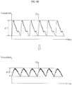
- FIGS. 5A to 6B are diagrams explaining operation of the motor driving device illustrated in FIG. 4 .
- FIG. 5A illustrates a DC link voltage Vdc generated in the case in which the low-capacitance DC link capacitor C is connected to the rectifier 410 without using the boost converter 420 of FIG. 4 .
- the DC link voltage Vdc cannot be smoothed by the low-capacitance DC link capacitor C and, as such, is directly applied in a pulsating state to the inverter 220.
- the pulsating DC link voltage Vdc has an average voltage level of about 0.7VL1 lower than a peak voltage level VL1.
- the inverter 220 may generate 3-phase AC power, using a voltage of about 0.7VL1. However, it is difficult to achieve smooth motor driving at a voltage level lower than about 0.7VL1. For this reason, voltage usage rate becomes low.
- the low-capacitance DC link capacitor C has a reduced capacitance, current control thereof may be impossible and, as such, low input power factor characteristics may be exhibited.
- the boost converter 420 is arranged downstream of the rectifier 410 in accordance with the illustrated embodiment of the present invention, as illustrated in FIG. 4 .
- FIG. 6A illustrates a DC link voltage Vdc generated in the case in which the boost converter 420 and low-capacitance DC link capacitor C are used.
- the DC link voltage Vdc When the DC link voltage Vdc is boosted by VL2, using the boost converter 420, a pulsating voltage having a minimum voltage level of VL2 and a peak voltage level of VL2 + VL1 is output to a DC link.
- the DC link voltage Vdc has an average voltage level of about VL1.
- the inverter 220 Since the inverter 220 generates 3-phase AC power, using a voltage of about VL1, it may be possible to achieve smooth motor driving in a large portion of the overall voltage period. Accordingly, increased voltage usage rate is exhibited. In addition, an operation range of the motor is widened.
- torque ripple corresponding to ⁇ T2 smaller than ⁇ T1 may be generated, as illustrated in FIG. 6B . That is, torque ripple is considerably reduced in this case.
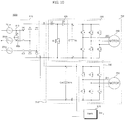
- FIG. 7 is a circuit diagram illustrating a motor driving device according to an embodiment of the present invention.
- the motor driving device which is designated by reference numeral "700" may include a rectifier 410, a boost converter 420, a first capacitor C, a first inverter 220, a second capacitor Cm, a second inverter 720, and a voltage dropper 910.
- the boost converter 420, first capacitor C, and first inverter 220 may constitute a compressor driving unit 705 for driving the compressor motor 250.
- the second capacitor Cm and second inverter 720 may constitute a first fan motor driving unit 710 for driving a first fan motor 750.
- the compressor motor 250 requires a high voltage, whereas the first fan motor 750 requires a lower voltage than that of the compressor motor 250.
- the voltage required for the compressor motor 250 and the voltage required for the first fan motor 750 are preferably taken into consideration because the voltages are different.
- the rectifier 410 is used in common for driving of both the compressor motor 250 and the first fan motor 750 in accordance with the illustrated embodiment of the present invention.
- the low-capacitance capacitor, the capacitor C, for driving of the compressor motor 250 and, as such, the first fan motor 750 may be stably driven by a lower voltage than that of the compressor motor 250.
- the compressor driving unit 705 and first fan driving unit 710 are illustrated as being connected in parallel to opposite ends a and b of the rectifier 410, which rectifies the single-phase input AC power 201.
- the boost converter 420, first capacitor C, and compressor inverter 220 are arranged in this order between opposite ends a and b of the rectifier 410.
- the second capacitor Cm and fan inverter 720 are arranged in this order between opposite ends a and b of the rectifier 410.
- the rectifier 410 is illustrated as having a configuration in which two pairs of arm switching elements are connected in parallel, and each arm switching element pair includes an upper arm switching element and a lower arm switching element, which are connected in series, such that the arm switching elements are connected in a bridged manner.
- the boost converter 420 may include an inductor L1 and a diode D1, which are connected in series between the rectifier 410 and the first capacitor C.
- the boost converter 420 may further include a switching element S1 connected between the inductor L1 and the diode D1. When the switching element S1 turns on, energy is stored in the inductor L1. When the switching element S1 turns off, the energy stored in the inductor L1 may be output via the diode D1.
- a voltage boosted to a certain level namely, an offset voltage, may be output from the boost converter 420.
- the first capacitor C preferably has a smaller capacitance than the second capacitor Cm. That is, the capacitance of the second capacitor Cm is preferably greater than the capacitance of the first capacitor C.
- the level of the voltage Vc stored in the first capacitor C is preferably higher than the level of the voltage Vcm stored in the second capacitor Cm.
- the voltage Vc stored in the first capacitor C may have a level of about 450V, whereas the voltage Vcm stored in the second capacitor Cm may have a level of about 300V.
- the first fan motor 750 may be stably driven in accordance with the DC voltage Vcm, which exhibits reduced pulsation.
- the voltage dropper 910 is connected between opposite ends c and d of the second capacitor Cm.
- the voltage dropper 910 drops a voltage Vcm across the second capacitor Cm, and outputs the dropped voltage.
- the voltage dropper 910 may include a switch mode power supply (SMPS).
- SMPS switch mode power supply
- the voltage dropper 910 may output operating voltages Vcc of about 15V, 7.5V, 5V, etc. Such operating voltages may be used as operating voltages of the inverter 220 and inverter controller 230.
- FIG. 8 is a circuit diagram illustrating a motor driving device according to another embodiment of the present invention.
- the motor driving device of FIG. 8 which is designated by reference numeral "800" is similar to the motor driving device 700 of FIG. 7 , except that the motor driving device 800 may further include a fan switching element Saf arranged between the power source of single-phase AC power 201 and the rectifier 410.
- a second fan motor 805, which is of an AC type, is directly driven.
- the compressor motor 250, first fan motor 750, and second fan motor 805 may be stably driven.
- FIG. 9 is a circuit diagram illustrating a motor driving device according to another embodiment of the present invention.
- the motor driving device of FIG. 9 which is designated by reference numeral "900" is similar to the motor driving device 700 of FIG. 7 , except that 3-phase input AC power 201a, 201b, and 201c are used.
- a rectifier 510 is used to rectify the 3-phase input AC power 201a, 201b, and 201c input thereto, and then to output the rectified power.
- the rectifier 510 may include a 3-phase bridge diode.
- FIG. 9 illustrates a configuration of the rectifier 510 in which three pairs of arm switching elements are connected in parallel, and each arm switching element pair includes an upper arm switching element and a lower arm switching element, which are connected in series, such that the arm switching elements are connected in a bridged manner.
- FIG. 10 is a circuit diagram illustrating a motor driving device according to another embodiment of the present invention.
- the motor driving device of FIG. 10 which is designated by reference numeral "1000" is similar to the motor driving device 900 of FIG. 9 , except that the motor driving device 1000 may further include a fan switching element Saf arranged between two of the power sources of 3-phase AC power 201a, 201b, and 201c, for example, the power sources of AC power 201a and 201b.
- a fan switching element Saf arranged between two of the power sources of 3-phase AC power 201a, 201b, and 201c, for example, the power sources of AC power 201a and 201b.
- the second fan motor 805 which is of an AC type, is directly driven.
- the compressor motor 250, first fan motor 750, and second fan motor 805 may be stably driven.
- FIG. 11 is a block diagram illustrating an example of the inner configuration of the converter controller illustrated in FIG. 4 .
- the converter controller 215 may include an input current command generator 720, a current controller 730, and a feed-forward compensator 740.
- the input current command generator 720 may receive an input voltage Vs detected by the input voltage detector A, and may generate an input current command value I*s, based on the received input voltage Vs.
- the converter controller 215 may further include a substractor 725 to calculate a difference between the input current command value I*s and the input current Is detected by the input current detector D.
- the substractor 725 applies the calculated difference to the current controller 730.
- the current controller 730 generates a first switching control signal Sp1 corresponding to a first duty, based on the input current command value I*s and an input current Is detected by the input current detector D.
- the current controller 730 generates the first switching control signal corresponding to the first duty, based on a difference between the input current command value I*s and the input current Is.
- the feed-forward compensator 740 executes feed-forward compensation in order to remove disturbance of the input voltage Vs from the boost converter 420 and the DC link voltage Vdc. Accordingly, the feed-forward compensator 740 may generate a second switching control signal Sp2 corresponding to a second duty, taking into consideration removal of voltage disturbance.
- the converter controller 215 may further include an adder 735 to add the second switching control signal Sp2 to the first switching control signal Sp1.
- the adder 735 may output a converter switching control signal Scc, based on results of the addition. That is, the adder 735 may output the converter switching control signal Scc, taking into consideration the first and second duties.
- the operation method of the motor driving device or air conditioner according to the present invention can be realized as code, which can be written on a recording medium that can be read by a processor equipped in the motor driving device or air conditioner and can be read by a processor.
- the recording medium that can be read by a processor includes all kinds of recording media, on which data that can be read by a processor is written, such as a read only memory (ROM), a random access memory (RAM), a CD-ROM, a magnetic tape, a floppy disk, an optical data storage, and a carrier wave type (e.g., transmission over the Internet).
- the recording medium that can be read by a processor can be distributed to computer systems connected to one another on a network, and codes that can be read by a processor can be stored in the recording medium in a distributed manner and executed.
- the above-described motor driving device and the air conditioner including the same may achieve driving of both a compressor motor and a fan motor, using the same input AC power, even when the motor driving device uses a low-capacitance capacitor, through a configuration of the motor driving device including a rectifier to rectify input AC power, a boost converter to boost the rectified power from the rectifier, and to output the boosted power, a first capacitor to store a pulsating voltage from the boost converter, a first inverter including a plurality of switching elements, the first inverter outputting, to a compressor motor, AC power transformed using a voltage across the first capacitor, a second capacitor to store the rectified power from the rectifier, a second inverter including a plurality of switching elements, the second inverter outputting, to a first fan motor, AC power transformed using a voltage across the second capacitor, and a voltage dropper to drop the voltage across the second capacitor, and to output the dropped voltage.
- the voltage boosted by the boost converter is used in a compressor inverter, that is, the first inverter, and, as such, torque ripple generated during driving of the motor may be reduced.
- an improvement in power factor may be achieved in accordance with use of the boost converter.
Landscapes
- Engineering & Computer Science (AREA)
- Mechanical Engineering (AREA)
- General Engineering & Computer Science (AREA)
- Power Engineering (AREA)
- Physics & Mathematics (AREA)
- Chemical & Material Sciences (AREA)
- Combustion & Propulsion (AREA)
- Thermal Sciences (AREA)
- Fluid Mechanics (AREA)
- Inverter Devices (AREA)
- Control Of Ac Motors In General (AREA)
Claims (12)
- Dispositif d'entraînement par moteur (700) comprenant :un redresseur (410) pour redresser un courant alternatif d'entrée ;un convertisseur élévateur (420) pour élever la puissance redressée du redresseur (410), et pour sortir la puissance élevée ;un premier condensateur (C) pour stocker une tension de pulsation du convertisseur élévateur (420) ;un premier onduleur (220) comprenant une pluralité d'éléments de commutation, le premier onduleur transmettant, à un moteur de compresseur (102b), un courant alternatif transformé en utilisant une tension traversant le premier condensateur (C) ;le dispositif d'entraînement par moteur (700) étant caractérisé en ce qu'il comprend :un second condensateur (Cm) pour stocker la puissance redressée du redresseur (410) ;un second onduleur (720) comprenant une pluralité d'éléments de commutation, le second onduleur (720) transmettant, à un premier moteur de ventilateur (750), un courant alternatif transformé en utilisant une tension traversant le second condensateur (Cm) ; etun élément de chute de tension (910) pour faire chuter la tension traversant le second condensateur (Cm) et pour sortir la tension baissée.
- Dispositif d'entraînement par moteur (700) selon la revendication 1, comprenant en outre :un élément de commutation de ventilateur (Saf) agencé entre une source de courant du courant alternatif d'entrée et le redresseur (410),dans lequel un second moteur de ventilateur (805) est entraîné selon une opération de marche de l'élément de commutation de ventilateur (Saf).
- Dispositif d'entraînement par moteur (700) selon la revendication 1 ou 2, dans lequel le premier condensateur (C) a une plus petite capacité que le second condensateur (Cm).
- Dispositif d'entraînement par moteur (700) selon la revendication 1 ou 2, dans lequel la tension stockée dans le premier condensateur (C) a un niveau plus élevé que la tension stockée dans le second condensateur (Cm).
- Dispositif d'entraînement par moteur (700) selon l'une quelconque des revendications 1 à 4, dans lequel le premier condensateur (C) comprend un condensateur à film.
- Dispositif d'entraînement par moteur (700) selon l'une quelconque des revendications 1 à 5, dans lequel le convertisseur élévateur (420) comprend :un inducteur (L1) et une diode (D1) qui sont reliés en série entre le redresseur (410) et le premier condensateur (C) ; etun élément de commutation (S1) relié entre l'inducteur (L1) et la diode (D1).
- Dispositif d'entraînement par moteur (700) selon l'une quelconque des revendications 1 à 6, comprenant en outre :un détecteur de courant d'entrée (D) pour détecter un courant d'entrée du courant alternatif d'entrée ;un détecteur de tension d'entrée (A) pour détecter une tension d'entrée du courant alternatif d'entrée ; etun contrôleur de convertisseur (215) pour sortir un signal de contrôler de convertisseur pour contrôler un élément de commutation (S1) dans le convertisseur élévateur (420) sur la base du courant d'entrée et de la tension d'entrée.
- Dispositif d'entraînement par moteur (700) selon la revendication 7, dans lequel le contrôleur de convertisseur (215) comprend :un générateur de commande de courant d'entrée (720) pour générer une valeur de commande de courant d'entrée sur la base de la tension d'entrée détectée ; etun contrôleur de courant (730) pour générer un premier signal de contrôle de commutation sur la base du courant d'entrée détecté et de la valeur de commande de courant d'entrée.
- Dispositif d'entraînement par moteur (700) selon la revendication 7 ou 8, dans lequel :le contrôleur de convertisseur (215) comprend en outre un précompensateur (740) pour générer un second signal de contrôle de commutation ; etle contrôleur de convertisseur (215) sort le signal de contrôle de commutation de convertisseur sur la base du premier signal de contrôle de commutation et du second signal de contrôle de commutation.
- Dispositif d'entraînement par moteur (700) selon l'une quelconque des revendications 1 à 9, comprenant en outre :un détecteur de tension de liaison de courant continu (B) pour détecter une première tension de liaison de courant continu entre le convertisseur élévateur (420) et le premier onduleur (220) ;un détecteur de courant de sortie (E) pour détecter un courant de sortie passant par le moteur de compresseur (102b) ; etun contrôleur d'onduleur (230) pour contrôler le premier onduleur (220) sur la base de la tension de liaison de courant continu détectée et le courant de sortie détecté.
- Climatiseur comprenant un dispositif d'entraînement par moteur (700) selon l'une quelconque des revendications 1 à 10.
- Procédé de fonctionnement d'un dispositif d'entraînement par moteur (100) selon l'une quelconque des revendications 1 à 10 et/ou de fonctionnement d'un climatiseur selon la revendication 11.
Applications Claiming Priority (1)
| Application Number | Priority Date | Filing Date | Title |
|---|---|---|---|
| KR1020140069654A KR102308028B1 (ko) | 2014-06-09 | 2014-06-09 | 모터 구동장치 및 이를 구비하는 공기조화기 |
Publications (2)
| Publication Number | Publication Date |
|---|---|
| EP2955455A1 EP2955455A1 (fr) | 2015-12-16 |
| EP2955455B1 true EP2955455B1 (fr) | 2017-01-11 |
Family
ID=53385522
Family Applications (1)
| Application Number | Title | Priority Date | Filing Date |
|---|---|---|---|
| EP15171042.3A Active EP2955455B1 (fr) | 2014-06-09 | 2015-06-08 | Dispositif d'entraînement par moteur et climatiseur comprenant celui-ci |
Country Status (4)
| Country | Link |
|---|---|
| US (1) | US9625190B2 (fr) |
| EP (1) | EP2955455B1 (fr) |
| KR (1) | KR102308028B1 (fr) |
| CN (1) | CN105141194B (fr) |
Families Citing this family (29)
| Publication number | Priority date | Publication date | Assignee | Title |
|---|---|---|---|---|
| JP5937619B2 (ja) * | 2011-12-14 | 2016-06-22 | 三菱電機株式会社 | ヒートポンプ装置ならびに、それを備えた空気調和機、ヒートポンプ給湯機、冷蔵庫、および冷凍機 |
| KR102422899B1 (ko) * | 2015-06-26 | 2022-07-19 | 엘지전자 주식회사 | 전력변환장치 및 이를 구비하는 공기조화기 |
| US10411619B2 (en) * | 2015-08-28 | 2019-09-10 | Regal Beloit America, Inc. | Motor controller, drive circuit, and methods for combined electric motor control |
| CN107026587A (zh) * | 2016-01-29 | 2017-08-08 | 台达电子工业股份有限公司 | 多个风扇的驱动装置 |
| US11431267B2 (en) | 2016-01-29 | 2022-08-30 | Delta Electronics, Inc. | Plural-fans driving apparatus |
| KR102542120B1 (ko) * | 2016-03-14 | 2023-06-09 | 엘지전자 주식회사 | 팬 모터 구동장치 및 이를 구비하는 공기조화기 |
| WO2017163451A1 (fr) * | 2016-03-25 | 2017-09-28 | 東芝キヤリア株式会社 | Dispositif de pompe à chaleur |
| US10305373B2 (en) | 2016-04-15 | 2019-05-28 | Emerson Climate Technologies, Inc. | Input reference signal generation systems and methods |
| US10075065B2 (en) | 2016-04-15 | 2018-09-11 | Emerson Climate Technologies, Inc. | Choke and EMI filter circuits for power factor correction circuits |
| US10312798B2 (en) * | 2016-04-15 | 2019-06-04 | Emerson Electric Co. | Power factor correction circuits and methods including partial power factor correction operation for boost and buck power converters |
| US10763740B2 (en) | 2016-04-15 | 2020-09-01 | Emerson Climate Technologies, Inc. | Switch off time control systems and methods |
| US9933842B2 (en) | 2016-04-15 | 2018-04-03 | Emerson Climate Technologies, Inc. | Microcontroller architecture for power factor correction converter |
| US10656026B2 (en) | 2016-04-15 | 2020-05-19 | Emerson Climate Technologies, Inc. | Temperature sensing circuit for transmitting data across isolation barrier |
| US10284132B2 (en) | 2016-04-15 | 2019-05-07 | Emerson Climate Technologies, Inc. | Driver for high-frequency switching voltage converters |
| US10277115B2 (en) | 2016-04-15 | 2019-04-30 | Emerson Climate Technologies, Inc. | Filtering systems and methods for voltage control |
| US9965928B2 (en) | 2016-04-15 | 2018-05-08 | Emerson Climate Technologies, Inc. | System and method for displaying messages in a column-by-column format via an array of LEDs connected to a circuit of a compressor |
| ITUA20162878A1 (it) * | 2016-04-26 | 2017-10-26 | Phase Motion Control S P A | Dispositivo di alimentazione e azionamento per un motore elettrico a magneti permanenti |
| JP6552733B2 (ja) * | 2016-06-17 | 2019-07-31 | 三菱電機株式会社 | モータシステム、モータ駆動装置、冷凍サイクル装置および空気調和機 |
| KR20180040376A (ko) * | 2016-10-12 | 2018-04-20 | 엘지전자 주식회사 | 전력 변환 장치 및 이를 포함하는 공기 조화기 |
| US10985608B2 (en) | 2016-12-13 | 2021-04-20 | General Electric Company | Back-up power system for a component and method of assembling same |
| US10518662B2 (en) | 2017-06-22 | 2019-12-31 | Thermo King Corporation | Method and system for power management using a power converter in transport |
| US10696175B2 (en) * | 2017-08-16 | 2020-06-30 | Ford Global Technologies, Llc | Variable inverter output |
| JP7154019B2 (ja) * | 2018-03-08 | 2022-10-17 | ナブテスコ株式会社 | Ac-ac電力変換装置 |
| EP3789534A4 (fr) * | 2018-05-04 | 2022-02-16 | Lg Electronics Inc. | Appareil de traitement de vêtement et son procédé de commande |
| JP7247152B2 (ja) * | 2019-09-30 | 2023-03-28 | ダイキン工業株式会社 | モータ駆動方法及びモータ駆動装置 |
| CN110762808A (zh) * | 2019-10-31 | 2020-02-07 | 广东美的制冷设备有限公司 | 驱动控制电路及空调器 |
| CN111900870A (zh) * | 2020-07-27 | 2020-11-06 | 珠海格力电器股份有限公司 | 一种变频器的供电控制装置、变频器和电机 |
| WO2022172418A1 (fr) * | 2021-02-12 | 2022-08-18 | 三菱電機株式会社 | Dispositif de conversion de puissance, dispositif d'entraînement de moteur et instrument d'application de cycle de réfrigération |
| CN116783811A (zh) * | 2021-02-12 | 2023-09-19 | 三菱电机株式会社 | 电力转换装置、马达驱动装置以及制冷循环应用设备 |
Family Cites Families (15)
| Publication number | Priority date | Publication date | Assignee | Title |
|---|---|---|---|---|
| AU664786B2 (en) * | 1993-01-21 | 1995-11-30 | Fujitsu General Limited | Control device for air conditioner |
| JPH07324844A (ja) * | 1994-05-31 | 1995-12-12 | Sanyo Electric Co Ltd | 6方向切替弁及びそれを用いた冷凍装置 |
| TW328190B (en) * | 1994-06-14 | 1998-03-11 | Toshiba Co Ltd | Control device of brushless motor and method of fault detection and air conditioner |
| JPH0835713A (ja) * | 1994-07-26 | 1996-02-06 | Fujitsu General Ltd | 空気調和機の制御方法およびその装置 |
| US5702551A (en) * | 1996-04-03 | 1997-12-30 | The Procter & Gamble Company | Method for assembling a multi-piece absorbent article |
| JP3694614B2 (ja) * | 1999-06-04 | 2005-09-14 | 株式会社日立製作所 | 空気調和機およびブラシレスモータ制御装置 |
| KR20030006423A (ko) * | 2001-07-12 | 2003-01-23 | 주식회사 포스코 | 유도 전동기 구동회로 |
| KR100664085B1 (ko) * | 2005-11-24 | 2007-01-03 | 엘지전자 주식회사 | 공기 조화기의 제어 장치 |
| JP4665809B2 (ja) * | 2006-03-24 | 2011-04-06 | トヨタ自動車株式会社 | 電動機駆動制御システム |
| KR100964368B1 (ko) * | 2007-10-31 | 2010-06-17 | 엘지전자 주식회사 | 공기조화기의 전동기 제어방법 및 그 제어 장치 |
| KR101463159B1 (ko) * | 2007-12-21 | 2014-11-20 | 엘지전자 주식회사 | 공기조화기의 전동기 제어장치 |
| JP2010161907A (ja) * | 2009-01-09 | 2010-07-22 | Toyota Motor Corp | モータ駆動制御システムの制御装置 |
| KR20100133635A (ko) * | 2009-06-12 | 2010-12-22 | 엘지전자 주식회사 | 공기조화기의 전동기 구동장치 |
| KR20110014435A (ko) * | 2009-08-05 | 2011-02-11 | 엘지전자 주식회사 | 공기조화기 |
| US8575778B2 (en) * | 2010-01-12 | 2013-11-05 | Ford Global Technologies, Llc | Variable voltage converter (VVC) with integrated battery charger |
-
2014
- 2014-06-09 KR KR1020140069654A patent/KR102308028B1/ko active Active
-
2015
- 2015-06-08 EP EP15171042.3A patent/EP2955455B1/fr active Active
- 2015-06-08 US US14/733,601 patent/US9625190B2/en active Active
- 2015-06-09 CN CN201510313394.0A patent/CN105141194B/zh active Active
Non-Patent Citations (1)
| Title |
|---|
| None * |
Also Published As
| Publication number | Publication date |
|---|---|
| CN105141194A (zh) | 2015-12-09 |
| US9625190B2 (en) | 2017-04-18 |
| CN105141194B (zh) | 2018-03-02 |
| EP2955455A1 (fr) | 2015-12-16 |
| KR102308028B1 (ko) | 2021-09-30 |
| KR20150141085A (ko) | 2015-12-17 |
| US20150354870A1 (en) | 2015-12-10 |
Similar Documents
| Publication | Publication Date | Title |
|---|---|---|
| EP2955455B1 (fr) | Dispositif d'entraînement par moteur et climatiseur comprenant celui-ci | |
| EP2955456B1 (fr) | Dispositif d'entrainement par moteur et climatiseur comprenant celui-ci | |
| US9941807B2 (en) | Power conversion apparatus and air conditioner including the same | |
| EP2779406B1 (fr) | Convertisseur de puissance et climatiseur comportant celui-ci | |
| US10344998B2 (en) | Air conditioner | |
| US10587182B2 (en) | Power conversion device having a control unit that outputs based on detected inductor current | |
| US20090160382A1 (en) | Motor controller of air conditioner | |
| EP2884641A1 (fr) | Dispositif d'entraînement par moteur et climatiseur comprenant celui-ci | |
| US10516331B2 (en) | Power conversion device and air conditioner comprising same | |
| KR101936631B1 (ko) | 모터 구동장치 및 이를 구비하는 공기조화기 | |
| KR102203433B1 (ko) | 모터 구동장치 및 이를 구비하는 공기조화기 | |
| KR20190005644A (ko) | 모터 구동장치 및 이를 구비하는 공기조화기 | |
| KR101905480B1 (ko) | 모터 구동장치 및 이를 구비하는 공기조화기 | |
| KR102199378B1 (ko) | 전력변환장치 및 이를 구비하는 공기조화기 | |
| KR102366586B1 (ko) | 모터 구동장치 및 이를 구비하는 공기조화기 | |
| KR102366401B1 (ko) | 모터 구동장치 및 이를 구비하는 공기조화기 | |
| KR102010388B1 (ko) | 모터 구동장치 및 이를 구비하는 공기조화기 | |
| KR102317144B1 (ko) | 모터 구동장치 및 이를 구비하는 공기조화기 | |
| KR20200046848A (ko) | 모터 구동장치 및 공기조화기 | |
| KR102379836B1 (ko) | 모터 구동장치 및 이를 구비하는 공기조화기 | |
| KR102242773B1 (ko) | 전동기 구동장치 및 이를 구비하는 공기조화기 | |
| KR102313302B1 (ko) | 모터 구동장치 및 이를 구비하는 공기조화기 | |
| KR102136153B1 (ko) | 모터 구동장치 및 이를 구비하는 공기조화기 | |
| KR20170018688A (ko) | 전력변환장치 및 이를 구비하는 공기조화기 |
Legal Events
| Date | Code | Title | Description |
|---|---|---|---|
| PUAI | Public reference made under article 153(3) epc to a published international application that has entered the european phase |
Free format text: ORIGINAL CODE: 0009012 |
|
| 17P | Request for examination filed |
Effective date: 20150708 |
|
| AK | Designated contracting states |
Kind code of ref document: A1 Designated state(s): AL AT BE BG CH CY CZ DE DK EE ES FI FR GB GR HR HU IE IS IT LI LT LU LV MC MK MT NL NO PL PT RO RS SE SI SK SM TR |
|
| AX | Request for extension of the european patent |
Extension state: BA ME |
|
| RBV | Designated contracting states (corrected) |
Designated state(s): AL AT BE BG CH CY CZ DE DK EE ES FI FR GB GR HR HU IE IS IT LI LT LU LV MC MK MT NL NO PL PT RO RS SE SI SK SM TR |
|
| GRAP | Despatch of communication of intention to grant a patent |
Free format text: ORIGINAL CODE: EPIDOSNIGR1 |
|
| RIC1 | Information provided on ipc code assigned before grant |
Ipc: F24F 11/00 20060101AFI20160623BHEP Ipc: H02M 1/42 20070101ALI20160623BHEP Ipc: H02M 1/00 20060101ALI20160623BHEP Ipc: H02M 5/458 20060101ALI20160623BHEP Ipc: H02P 6/04 20160101ALI20160623BHEP Ipc: F25B 49/02 20060101ALI20160623BHEP Ipc: F25B 31/02 20060101ALI20160623BHEP Ipc: H02P 27/06 20060101ALI20160623BHEP Ipc: H02P 5/74 20060101ALI20160623BHEP |
|
| INTG | Intention to grant announced |
Effective date: 20160721 |
|
| GRAS | Grant fee paid |
Free format text: ORIGINAL CODE: EPIDOSNIGR3 |
|
| GRAA | (expected) grant |
Free format text: ORIGINAL CODE: 0009210 |
|
| AK | Designated contracting states |
Kind code of ref document: B1 Designated state(s): AL AT BE BG CH CY CZ DE DK EE ES FI FR GB GR HR HU IE IS IT LI LT LU LV MC MK MT NL NO PL PT RO RS SE SI SK SM TR |
|
| REG | Reference to a national code |
Ref country code: GB Ref legal event code: FG4D |
|
| REG | Reference to a national code |
Ref country code: CH Ref legal event code: EP |
|
| REG | Reference to a national code |
Ref country code: AT Ref legal event code: REF Ref document number: 861667 Country of ref document: AT Kind code of ref document: T Effective date: 20170115 |
|
| REG | Reference to a national code |
Ref country code: IE Ref legal event code: FG4D |
|
| REG | Reference to a national code |
Ref country code: DE Ref legal event code: R096 Ref document number: 602015001259 Country of ref document: DE |
|
| REG | Reference to a national code |
Ref country code: LT Ref legal event code: MG4D |
|
| REG | Reference to a national code |
Ref country code: FR Ref legal event code: PLFP Year of fee payment: 3 |
|
| REG | Reference to a national code |
Ref country code: NL Ref legal event code: MP Effective date: 20170111 |
|
| REG | Reference to a national code |
Ref country code: AT Ref legal event code: MK05 Ref document number: 861667 Country of ref document: AT Kind code of ref document: T Effective date: 20170111 |
|
| PG25 | Lapsed in a contracting state [announced via postgrant information from national office to epo] |
Ref country code: NL Free format text: LAPSE BECAUSE OF FAILURE TO SUBMIT A TRANSLATION OF THE DESCRIPTION OR TO PAY THE FEE WITHIN THE PRESCRIBED TIME-LIMIT Effective date: 20170111 |
|
| PG25 | Lapsed in a contracting state [announced via postgrant information from national office to epo] |
Ref country code: FI Free format text: LAPSE BECAUSE OF FAILURE TO SUBMIT A TRANSLATION OF THE DESCRIPTION OR TO PAY THE FEE WITHIN THE PRESCRIBED TIME-LIMIT Effective date: 20170111 Ref country code: NO Free format text: LAPSE BECAUSE OF FAILURE TO SUBMIT A TRANSLATION OF THE DESCRIPTION OR TO PAY THE FEE WITHIN THE PRESCRIBED TIME-LIMIT Effective date: 20170411 Ref country code: HR Free format text: LAPSE BECAUSE OF FAILURE TO SUBMIT A TRANSLATION OF THE DESCRIPTION OR TO PAY THE FEE WITHIN THE PRESCRIBED TIME-LIMIT Effective date: 20170111 Ref country code: LT Free format text: LAPSE BECAUSE OF FAILURE TO SUBMIT A TRANSLATION OF THE DESCRIPTION OR TO PAY THE FEE WITHIN THE PRESCRIBED TIME-LIMIT Effective date: 20170111 Ref country code: IS Free format text: LAPSE BECAUSE OF FAILURE TO SUBMIT A TRANSLATION OF THE DESCRIPTION OR TO PAY THE FEE WITHIN THE PRESCRIBED TIME-LIMIT Effective date: 20170511 Ref country code: GR Free format text: LAPSE BECAUSE OF FAILURE TO SUBMIT A TRANSLATION OF THE DESCRIPTION OR TO PAY THE FEE WITHIN THE PRESCRIBED TIME-LIMIT Effective date: 20170412 |
|
| PG25 | Lapsed in a contracting state [announced via postgrant information from national office to epo] |
Ref country code: PT Free format text: LAPSE BECAUSE OF FAILURE TO SUBMIT A TRANSLATION OF THE DESCRIPTION OR TO PAY THE FEE WITHIN THE PRESCRIBED TIME-LIMIT Effective date: 20170511 Ref country code: AT Free format text: LAPSE BECAUSE OF FAILURE TO SUBMIT A TRANSLATION OF THE DESCRIPTION OR TO PAY THE FEE WITHIN THE PRESCRIBED TIME-LIMIT Effective date: 20170111 Ref country code: PL Free format text: LAPSE BECAUSE OF FAILURE TO SUBMIT A TRANSLATION OF THE DESCRIPTION OR TO PAY THE FEE WITHIN THE PRESCRIBED TIME-LIMIT Effective date: 20170111 Ref country code: LV Free format text: LAPSE BECAUSE OF FAILURE TO SUBMIT A TRANSLATION OF THE DESCRIPTION OR TO PAY THE FEE WITHIN THE PRESCRIBED TIME-LIMIT Effective date: 20170111 Ref country code: RS Free format text: LAPSE BECAUSE OF FAILURE TO SUBMIT A TRANSLATION OF THE DESCRIPTION OR TO PAY THE FEE WITHIN THE PRESCRIBED TIME-LIMIT Effective date: 20170111 Ref country code: ES Free format text: LAPSE BECAUSE OF FAILURE TO SUBMIT A TRANSLATION OF THE DESCRIPTION OR TO PAY THE FEE WITHIN THE PRESCRIBED TIME-LIMIT Effective date: 20170111 Ref country code: BG Free format text: LAPSE BECAUSE OF FAILURE TO SUBMIT A TRANSLATION OF THE DESCRIPTION OR TO PAY THE FEE WITHIN THE PRESCRIBED TIME-LIMIT Effective date: 20170411 Ref country code: SE Free format text: LAPSE BECAUSE OF FAILURE TO SUBMIT A TRANSLATION OF THE DESCRIPTION OR TO PAY THE FEE WITHIN THE PRESCRIBED TIME-LIMIT Effective date: 20170111 |
|
| REG | Reference to a national code |
Ref country code: DE Ref legal event code: R097 Ref document number: 602015001259 Country of ref document: DE |
|
| PG25 | Lapsed in a contracting state [announced via postgrant information from national office to epo] |
Ref country code: SK Free format text: LAPSE BECAUSE OF FAILURE TO SUBMIT A TRANSLATION OF THE DESCRIPTION OR TO PAY THE FEE WITHIN THE PRESCRIBED TIME-LIMIT Effective date: 20170111 Ref country code: EE Free format text: LAPSE BECAUSE OF FAILURE TO SUBMIT A TRANSLATION OF THE DESCRIPTION OR TO PAY THE FEE WITHIN THE PRESCRIBED TIME-LIMIT Effective date: 20170111 Ref country code: CZ Free format text: LAPSE BECAUSE OF FAILURE TO SUBMIT A TRANSLATION OF THE DESCRIPTION OR TO PAY THE FEE WITHIN THE PRESCRIBED TIME-LIMIT Effective date: 20170111 Ref country code: RO Free format text: LAPSE BECAUSE OF FAILURE TO SUBMIT A TRANSLATION OF THE DESCRIPTION OR TO PAY THE FEE WITHIN THE PRESCRIBED TIME-LIMIT Effective date: 20170111 |
|
| PLBE | No opposition filed within time limit |
Free format text: ORIGINAL CODE: 0009261 |
|
| STAA | Information on the status of an ep patent application or granted ep patent |
Free format text: STATUS: NO OPPOSITION FILED WITHIN TIME LIMIT |
|
| PG25 | Lapsed in a contracting state [announced via postgrant information from national office to epo] |
Ref country code: SM Free format text: LAPSE BECAUSE OF FAILURE TO SUBMIT A TRANSLATION OF THE DESCRIPTION OR TO PAY THE FEE WITHIN THE PRESCRIBED TIME-LIMIT Effective date: 20170111 Ref country code: DK Free format text: LAPSE BECAUSE OF FAILURE TO SUBMIT A TRANSLATION OF THE DESCRIPTION OR TO PAY THE FEE WITHIN THE PRESCRIBED TIME-LIMIT Effective date: 20170111 |
|
| 26N | No opposition filed |
Effective date: 20171012 |
|
| PG25 | Lapsed in a contracting state [announced via postgrant information from national office to epo] |
Ref country code: MC Free format text: LAPSE BECAUSE OF FAILURE TO SUBMIT A TRANSLATION OF THE DESCRIPTION OR TO PAY THE FEE WITHIN THE PRESCRIBED TIME-LIMIT Effective date: 20170111 |
|
| PG25 | Lapsed in a contracting state [announced via postgrant information from national office to epo] |
Ref country code: SI Free format text: LAPSE BECAUSE OF FAILURE TO SUBMIT A TRANSLATION OF THE DESCRIPTION OR TO PAY THE FEE WITHIN THE PRESCRIBED TIME-LIMIT Effective date: 20170111 |
|
| REG | Reference to a national code |
Ref country code: IE Ref legal event code: MM4A |
|
| PG25 | Lapsed in a contracting state [announced via postgrant information from national office to epo] |
Ref country code: LU Free format text: LAPSE BECAUSE OF NON-PAYMENT OF DUE FEES Effective date: 20170608 Ref country code: IE Free format text: LAPSE BECAUSE OF NON-PAYMENT OF DUE FEES Effective date: 20170608 |
|
| REG | Reference to a national code |
Ref country code: BE Ref legal event code: MM Effective date: 20170630 |
|
| REG | Reference to a national code |
Ref country code: FR Ref legal event code: PLFP Year of fee payment: 4 |
|
| PG25 | Lapsed in a contracting state [announced via postgrant information from national office to epo] |
Ref country code: BE Free format text: LAPSE BECAUSE OF NON-PAYMENT OF DUE FEES Effective date: 20170630 |
|
| PG25 | Lapsed in a contracting state [announced via postgrant information from national office to epo] |
Ref country code: MT Free format text: LAPSE BECAUSE OF NON-PAYMENT OF DUE FEES Effective date: 20170608 |
|
| REG | Reference to a national code |
Ref country code: CH Ref legal event code: PL |
|
| PG25 | Lapsed in a contracting state [announced via postgrant information from national office to epo] |
Ref country code: LI Free format text: LAPSE BECAUSE OF NON-PAYMENT OF DUE FEES Effective date: 20180630 Ref country code: CH Free format text: LAPSE BECAUSE OF NON-PAYMENT OF DUE FEES Effective date: 20180630 |
|
| PG25 | Lapsed in a contracting state [announced via postgrant information from national office to epo] |
Ref country code: HU Free format text: LAPSE BECAUSE OF FAILURE TO SUBMIT A TRANSLATION OF THE DESCRIPTION OR TO PAY THE FEE WITHIN THE PRESCRIBED TIME-LIMIT; INVALID AB INITIO Effective date: 20150608 |
|
| PG25 | Lapsed in a contracting state [announced via postgrant information from national office to epo] |
Ref country code: CY Free format text: LAPSE BECAUSE OF FAILURE TO SUBMIT A TRANSLATION OF THE DESCRIPTION OR TO PAY THE FEE WITHIN THE PRESCRIBED TIME-LIMIT Effective date: 20170111 |
|
| PG25 | Lapsed in a contracting state [announced via postgrant information from national office to epo] |
Ref country code: MK Free format text: LAPSE BECAUSE OF FAILURE TO SUBMIT A TRANSLATION OF THE DESCRIPTION OR TO PAY THE FEE WITHIN THE PRESCRIBED TIME-LIMIT Effective date: 20170111 |
|
| GBPC | Gb: european patent ceased through non-payment of renewal fee |
Effective date: 20190608 |
|
| PG25 | Lapsed in a contracting state [announced via postgrant information from national office to epo] |
Ref country code: TR Free format text: LAPSE BECAUSE OF FAILURE TO SUBMIT A TRANSLATION OF THE DESCRIPTION OR TO PAY THE FEE WITHIN THE PRESCRIBED TIME-LIMIT Effective date: 20170111 |
|
| PG25 | Lapsed in a contracting state [announced via postgrant information from national office to epo] |
Ref country code: GB Free format text: LAPSE BECAUSE OF NON-PAYMENT OF DUE FEES Effective date: 20190608 |
|
| PG25 | Lapsed in a contracting state [announced via postgrant information from national office to epo] |
Ref country code: AL Free format text: LAPSE BECAUSE OF FAILURE TO SUBMIT A TRANSLATION OF THE DESCRIPTION OR TO PAY THE FEE WITHIN THE PRESCRIBED TIME-LIMIT Effective date: 20170111 |
|
| PGFP | Annual fee paid to national office [announced via postgrant information from national office to epo] |
Ref country code: DE Payment date: 20250508 Year of fee payment: 11 |
|
| PGFP | Annual fee paid to national office [announced via postgrant information from national office to epo] |
Ref country code: IT Payment date: 20250512 Year of fee payment: 11 |
|
| PGFP | Annual fee paid to national office [announced via postgrant information from national office to epo] |
Ref country code: FR Payment date: 20250513 Year of fee payment: 11 |