EP2955497B1 - Kraftsensor mit Kompensation - Google Patents
Kraftsensor mit Kompensation Download PDFInfo
- Publication number
- EP2955497B1 EP2955497B1 EP14171660.5A EP14171660A EP2955497B1 EP 2955497 B1 EP2955497 B1 EP 2955497B1 EP 14171660 A EP14171660 A EP 14171660A EP 2955497 B1 EP2955497 B1 EP 2955497B1
- Authority
- EP
- European Patent Office
- Prior art keywords
- force
- responsive component
- output
- brownian motion
- circuit
- Prior art date
- Legal status (The legal status is an assumption and is not a legal conclusion. Google has not performed a legal analysis and makes no representation as to the accuracy of the status listed.)
- Active
Links
Images


Classifications
-
- G—PHYSICS
- G01—MEASURING; TESTING
- G01L—MEASURING FORCE, STRESS, TORQUE, WORK, MECHANICAL POWER, MECHANICAL EFFICIENCY, OR FLUID PRESSURE
- G01L25/00—Testing or calibrating of apparatus for measuring force, torque, work, mechanical power, or mechanical efficiency
-
- G—PHYSICS
- G01—MEASURING; TESTING
- G01L—MEASURING FORCE, STRESS, TORQUE, WORK, MECHANICAL POWER, MECHANICAL EFFICIENCY, OR FLUID PRESSURE
- G01L1/00—Measuring force or stress, in general
- G01L1/10—Measuring force or stress, in general by measuring variations of frequency of stressed vibrating elements, e.g. of stressed strings
-
- G—PHYSICS
- G01—MEASURING; TESTING
- G01L—MEASURING FORCE, STRESS, TORQUE, WORK, MECHANICAL POWER, MECHANICAL EFFICIENCY, OR FLUID PRESSURE
- G01L1/00—Measuring force or stress, in general
- G01L1/26—Auxiliary measures taken, or devices used, in connection with the measurement of force, e.g. for preventing influence of transverse components of force, for preventing overload
-
- G—PHYSICS
- G01—MEASURING; TESTING
- G01Q—SCANNING-PROBE TECHNIQUES OR APPARATUS; APPLICATIONS OF SCANNING-PROBE TECHNIQUES, e.g. SCANNING PROBE MICROSCOPY [SPM]
- G01Q60/00—Particular types of SPM [Scanning Probe Microscopy] or microscopes; Essential components thereof
- G01Q60/24—AFM [Atomic Force Microscopy] or apparatus therefor, e.g. AFM probes
Definitions
- aspects of various embodiments are directed to force sensing and sensors.
- Various sensors such as pressure sensors, accelerometers, gyros, and microphones measure an external force by detecting the displacement of a mechanical structure. The displacement of this structure is converted to an external signal.
- variations in the sensor and the displacement detector can vary in time. For instance, accurate force measurement benefits from accurately knowing the spring constant k of the sensor.
- This constant can vary during operation due to, for example, variations in ambient conditions such as temperature, stress, thermal expansion and their effect on the spring constant.
- the spring constant can also vary due to permanent (irreversible) changes in the material and sensor properties, ageing, degradation, fatigue, contamination, threshold voltage shifts, charging and other mechanical and electronic variations in the sensor. Variations in manufacturing processes may also cause variations in the spring constant.
- calibration can be important for ensuring sensor accuracy. Calibration often involves using a reference force of known value. However, it can be difficult to generate a constant reference force for a variety of applications. For example, electrostatic forces can drift significantly due to effects such as gap variation ( e.g., due to temperature, stress or fatigue), charge accumulation and voltage drifts.
- a sensor chip as defined in claim 1.
- Various example embodiments are directed to sensors and their implementation.
- an apparatus includes a force-responsive component that exhibits a resonant frequency and moves in response to an applied force, with the movement being in accordance with a spring constant that is susceptible to fluctuation.
- a compensation/calibration-type circuit determines Brownian motion of the force-responsive component at the resonant frequency based on temperature.
- An output is generated based on the determined Brownian motion and movement of the force-responsive component, which is indicative of force applied to the apparatus.
- a force-responsive component which has a resonant frequency and which moves in response to an applied force, in accordance with a spring constant that is susceptible to fluctuation. Brownian motion of the force-responsive component at the resonant frequency is determined based on temperature. An output is generated based on the determined Brownian motion and movement of the force-responsive component, providing an indication of force applied to the apparatus.
- Various example embodiments are directed to sensor applications that implement Brownian noise, such as by compensating or calibrating mechanical sensors based on Brownian noise. Certain embodiments are directed to on-chip calibration that corrects for sensor variations, based on electronic measurement of Brownian motion of the chip. Such approaches may be implemented for pressure sensing, accelerometers, gyroscopes that measure Coriolis forces, microphones that measure gas pressures, atomic force microscopes that measure contact forces, and other force-based sensing applications.
- Various embodiments are directed to implementation with mechanical sensors, and addressing challenges such as those described in the background above, as may relate to obtaining an accurate absolute measurement of applied force F ext .
- the applied force is evaluated based on a spring constant of the sensor, which is adjusted via Brownian noise to accommodate variations in ambient conditions such as temperature, stress, thermal expansion and their effect on the spring constant, and to accommodate permanent (irreversible) changes in material and sensor properties such as those involving ageing, degradation, fatigue, contamination, threshold voltage shifts, charging and other mechanical and electronic variations in the sensor.
- an apparatus in accordance with another embodiment, includes a force-responsive component that moves in response to an applied force in accordance with a spring constant that is susceptible to fluctuation, and operable with a resonant frequency.
- a component may, for example, include a mass component and a spring component, as may be implemented with a pressure sensor, motion sensor or a variety of devices.
- a circuit coupled to the force-responsive component determines Brownian motion thereof, at the resonant frequency, based on temperature ( e.g., and upon a detected displacement of a mass in the pressure-responsive component). An output is generated, which is based on the determined Brownian motion and movement of the force-responsive component, and is indicative of force applied to the apparatus.
- the Brownian motion is used to determine a change in a value of the spring constant, and an output is generated using the determined change in value. This output correlates the detected movement of the force-responsive component to the force applied to the apparatus.
- a model of the movement of the force-responsive component is used to generate the output, in which the model is based upon characteristics of the force-responsive component including mass, temperature, geometry, damping, resonant frequency and the spring constant.
- a model is used to determine the spring constant from the measured Brownian motion. The model is based upon characteristics of the force-responsive component, such as mass, temperature, damping, resonant frequency, and geometry. The model may also be based on the characteristics of the Brownian motion detector and the temperature.
- a spectrum analyzer is coupled to detect a Brownian motion-based peak in resonance of the force-responsive component.
- the peak is integrated over a frequency range and the result of the integration is used to determine the Brownian motion of the force-responsive component, near or at the resonant frequency.
- Force-responsive components as discussed above are implemented in a variety of manners, to suit various applications.
- a force-responsive component provides a voltage output that characterizes the applied force, and that varies based upon the applied force and fluctuations in the spring constant.
- a temperature sensor senses temperature used in determining the Brownian motion
- a reference circuit provides a reference value for calibrating/compensating for motion detection with the force-responsive component (e.g., providing capacitance, resistance and/or voltage values that may be fixed).
- a spectrum analyzer having a fixed amplitude and frequency range is operable to analyze a value corresponding to a response of the force-responsive component to pressure. As such, displacement of the force-responsive component is detected using the fixed-capacitance source as a reference.
- Brownian motion noise is estimated based on an output of the spectrum analyzer indicative of a Brownian motion-based peak in resonance of the voltage output, and the estimated Brownian motion noise and detected temperature are used to determine a value of the spring constant.
- An output is then generated by determining pressure applied to the force-responsive component, based on the determined value of the spring constant, a model that relates the force on the sensor to the pressure and the detected displacement.
- a model that describes dependence of the voltage on atmospheric parameters is used to generate an output indicative of a corrected/compensated or calibrated senses pressure.
- a force-responsive component as discussed herein provides a voltage output that varies in response to pressure.
- An output characterizing pressure is generated by determining a spring constant of the force-responsive component based on the Brownian motion, and using the spring constant together with detected movement of the force-responsive component to determine an amount of pressure applied thereto.
- Brownian motion is determined in one or more of a variety of manners.
- noise due to random thermal excitations of the force-responsive component is filtered from an output indicative of a resonant frequency of the force-responsive component, and the Brownian motion is determined based upon the magnitude of a signal at the resonant frequency in the filtered output.
- Brownian motion is determined based on a frequency peak in a voltage spectrum corresponding to movement of the force-responsive component.
- Brownian motion is used to address pressure sensing issues in a variety of manners, to suit particular embodiments.
- the force generated by Brownian motion of atoms and molecules surrounding a sensor is used as a reference force. Since the amplitude of the Brownian force is determined by laws of thermodynamics, its magnitude is independent of sensor degradation or variations in the environment.
- An on-chip calibration approach thus involves temperature-based measuring of the motion response of a sensor to excitation by Brownian forces at one or more of the sensor's resonance frequencies, using a single chip.
- Brownian motion may be characterized as follows.
- the symbols ⁇ > indicate a time or ensemble average, and ⁇ x 2 > is sometimes called the mean squared displacement.
- ⁇ x 2 > an accurate value of ⁇ x 2 > can be obtained by taking the integral from f res -5 f res /Q to f res +5 f res /Q (and multiplying by 2 to account for the negative frequencies).
- Accurate electronic measurement of the Brownian motion at room temperature may be achieved in an electrical measurement at 0.2 mA.
- P.G. Steeneken K. Le Phan, M.J. Goossens, G.E.J. Koops, G.J.A.M. Brom, C. van der Avoort and J.T.M. van Beek, "Piezoresistive heat engine and refrigerator," Nature Physics 7, 354-359 (2011 ).
- a mechanical force sensor that can generally be modeled as a mechanical resonator with three unknown parameters: mass m, damping b and spring constant k. These can be rewritten in a spring constant k, resonance frequency ⁇ 0 and quality factor Q.
- ⁇ 0 and Q are determined by fitting the shape of the resonance spectrum.
- the resonance mode ⁇ x(f) 2 > caused by the Brownian motion is detected as a peak in the output voltage spectrum and separated from frequency-independent background noise contribution ⁇ V bg 2 (f)>, as may be implemented in accordance with the plots in Figure 3 .
- An on-chip spectrum analyzer is used to measure this peak, which is integrated over a sufficiently large frequency range after subtracting background noise.
- the integration is carried out electronically using a resolution bandwidth of the spectrum analyzer that is bigger than the peak width. In another implementation, the integration is carried out by taking a resolution bandwidth that is smaller than the peak width, measuring at many points and subsequently summing all points.
- FIG. 1 shows a sensor apparatus 100, in accordance with an example embodiment.
- the apparatus 100 includes a sensor chip 110 having a force-responsive component 120 having a resonant frequency and mechanical structure having mass "m” and spring constant “k” that is susceptible to fluctuation.
- a displacement detector 130 detects displacement of the mass "x,” and the apparatus measures external forces by the effect on the displacement.
- the displacement detector 130 converts an output of the force-responsive component 120 to an output signal (e.g., a voltage V out ).
- a calibration and pressure determination circuit 140 operates to compensate for variations in the spring constant k, based on a temperature input and determined Brownian motion.
- the circuit 140 determines Brownian motion of the force-responsive component at the resonant frequency based on temperature, and generates an output based on the determined Brownian motion and movement of the force-responsive component, with the output being indicative of force applied to the apparatus.
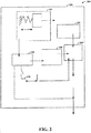
- Figure 2 shows another sensor apparatus 200 including a chip 210, in accordance with another example embodiment.
- a force-responsive component 220 has a mas m and spring-type aspect having a spring constant K, which provide an output based on an applied external force F ext and a force due to Brownian noise F Brownian noise .
- a displacement detector 230 detects displacement of the mass, and provides an indication of the detected displacement as a voltage V out to a spectrum analyzer 240.
- the spectrum analyzer 240 analyzes the displacement output for identifying peaks, and a temperature sensor 250 detects temperature on the chip 210.
- a calibration module 260 uses values from these components, along with a reference value provided by reference circuit 270, to determine a calibration/compensation output k/a, which is used to calibrate or otherwise compensate for errors in the detected displacement due to issues as discussed herein.
- the displacement detector 230 is calibrated by connecting it to the reference circuit 270, which may provide a value corresponding to a reference displacement distance x 0 .
- the 0.2 mA curve is at room temperature, and the remaining curves are measured by boosting the Brownian motion with a feedback system. Such a feedback system may be implemented with drift that is much less in time than drift exhibited by a sensor and displacement detector for which the plots are used. Boosting the Brownian motion at the resonance frequency facilitates detection and calibration methods and systems in certain implementations.
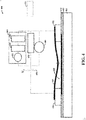
- FIG. 4 shows another sensor apparatus 400, in accordance with another example embodiment.
- the apparatus 400 includes substrate 410 upon which an electrical isolation or dielectric layers 412 and 414 are formed (one or more such layers may be implemented).
- Respective electrodes 420 an 422 are located on the isolation/dielectric layer 414, and a piezoresistive membrane 430 extends between the electrodes and defines an hermetic cavity 440.
- the arrow on the membrane 430 represents small amplitude Brownian/thermal motion. Resistance of the membrane 430 is responsive to deflection amplitude, and thus provides a detectable characterization of the deflecation, via electrodes 420 and 422.
- the apparatus 400 also includes a spectrum analyzer 460 that integrates spectral power using a bandpass filter 463 over a resonance peak of the membrane 430.
- the output of the bandpass filter 463 is passed through a rectifier/integrator 462 that rectifies and integrates the output.
- Voltmeter 461 is calibrated using a bandgap reference and Brownian motion.
- Resistor 470 has a relatively low temperature coefficient of resistance, and is coupled as shown in parallel with a DC voltmeter (providing V dc ) 480, and in series with DC voltage source V 0 450. Accordingly, the output of the voltmeter 461 can be used to determine ⁇ x 2 >, with the DC voltage V dc from the voltmeter being measure of ⁇ x> (DC displacement).
- a (P ambient -P ref ) k ⁇ x>, where A is the membrane area, P ambient is ambient pressure and P ref is a reference pressure.
- P ambient P ref + (kB T ⁇ x>)/(A ⁇ x 2 >), according to the temperature given by the sensor.
- aspects of Figure 2 may be implemented using plots as shown in Figure 3 .
- aspects shown in Figure 4 may be implemented with the apparatus 200 in Figure 2 , such as in place of the force-responsive component 220.
- various embodiments involve methods relating to the above and other discussion herein, with regard to manufacturing and/or operating the described and other sensing components.
- Various embodiments involve methods relating to the above and other discussion herein, with regard to manufacturing and/or operating the described and other sensing components.
- a “block” (also sometimes “logic circuitry” or “module”) is a circuit that carries out one or more of these or related operations/activities (e.g., detecting displacement, analyzing spectra, or calibrating).
- one or more modules are discrete logic circuits or programmable logic circuits configured and arranged for implementing these operations/activities, as in the circuit modules shown in Figure 2 .
- such a programmable circuit is one or more computer circuits programmed to execute a set (or sets) of instructions (and/or configuration data).
- the instructions can be in the form of firmware or software stored in and accessible from a memory (circuit).
- first and second modules include a combination of a CPU hardware-based circuit and a set of instructions in the form of firmware, where the first module includes a first CPU hardware circuit with one set of instructions and the second module includes a second CPU hardware circuit with another set of instructions.
- Certain embodiments are directed to a computer program product (e.g., nonvolatile memory device), which includes a machine or computer-readable medium having stored thereon instructions which may be executed by a computer (or other electronic device) to perform these operations/activities.
- a computer program product e.g., nonvolatile memory device
Landscapes
- Physics & Mathematics (AREA)
- General Physics & Mathematics (AREA)
- Measuring Fluid Pressure (AREA)
- Testing Or Calibration Of Command Recording Devices (AREA)
Claims (11)
- Ein Sensorchip (110, 210) aufweisend:eine kraft-responsive Komponente (120, 220), die eine Massekomponente und eine Federkomponente und eine Resonanzfrequenz hat und die konfiguriert und angeordnet ist, sich in Antwort auf eine ausgeübte Kraft zu bewegen in Übereinstimmung mit einer Federkonstante, die empfänglich für Fluktuation ist, und;eine Schaltung, die konfiguriert und angeordnet ist, Brownsche Bewegung der kraft-responsiven Komponente zu bestimmen bei der Resonanzfrequenz basierend auf Temperatur und eine Ausgabe zu erzeugen basierend auf der bestimmten Brownschen Bewegung und Bewegung der kraft-responsiven Komponente, wobei die Ausgabe indikativ ist für die Kraft, die auf ein Gerät ausgeübt wird,wobei die Schaltung umfassteinen Verschiebungsdetektor (130, 230), der konfiguriert und angeordnet ist, eine Spannungsausgabe bereitzustellen, die die ausgeübte Kraft charakterisiert und die sich basierend auf der ausgeübten Kraft und Fluktuationen der Federkonstante verändert,einen Temperatursensor (250),eine Referenzschaltung (270) einschließlich zumindest einem von einer Kapazität, einem Widerstand und einer Spannungsquelle undeinen Spektrumanalysator, der eine feste Amplitude und Frequenzbereich hat, wobei die Schaltung konfiguriert und angeordnet ist,zu detektieren Verschiebung der kraft-responsiven Komponente unter Verwendung des zumindest einen von einer Kapazität, einem Widerstand und einer Spannungsquelle,zu schätzen Brownsche Bewegung Rauschen basierend auf einer Ausgabe des Spektrumanalysators, die indikativ ist für einen auf Brownscher Bewegung basierenden Resonanzpeak der Spannungsausgabe,zu verwenden das geschätzte Brownsche Bewegung Rauschen und die Temperatur, die von dem Temperatursensor detektiert wird, um einen Wert der Federkonstante zu bestimmen, undzu erzeugen die Ausgabe, indem Druck bestimmt wird, der auf die kraft-responsive Komponente ausgeübt wird, basierend auf dem bestimmten Wert der Federkonstante und der detektierten Verschiebung.
- Der Sensorchip gemäß Anspruch 1, wobei die Schaltung konfiguriert und angeordnet ist, die Ausgabe zu erzeugen unter Verwendung eines Modells der Bewegung der kraft-responsiven Komponente, wobei das Modell basiert auf Eigenschaften der kraft-responsiven Komponente einschließlich Masse, Temperatur, Dämpfung, Resonanzfrequenz und der Federkonstante.
- Der Sensorchip gemäß Anspruch 1 oder 2, wobei die Schaltung konfiguriert und angeordnet ist, den Peak über einen Frequenzbereich zu integrieren und das Ergebnis der Integration zu verwenden, um die Brownsche Bewegung der kraft-responsiven Komponente bei ungefähr der Resonanzfrequenz zu bestimmen.
- Der Sensorchip gemäß Anspruch 3, wobei die Referenzschaltung konfiguriert und angeordnet ist mit einem Modell, das Abhängigkeit des Wertes von atmosphärischen Parametern beschreibt, und konfiguriert und angeordnet ist, das Modell zu verwenden, um den Wert zu erzeugen.
- Der Sensorchip gemäß einem vorherigen Anspruch, wobei die Schaltung konfiguriert und angeordnet ist, um die Brownsche Bewegung zu bestimmen mittels Filterns von Rauschen in einem Frequenzbereich, der eine Resonanzfrequenz umfasst, aus einer Ausgabe, die indikativ ist für Bewegung der kraft-responsiven Komponente, und zu bestimmen die mittlere quadratische Amplitude der Brownschen Bewegung basierend auf der gefilterten Ausgabe.
- Der Sensorchip gemäß einem vorherigen Anspruch, wobei die Schaltung konfiguriert und angeordnet ist, die Brownsche Bewegung zu bestimmen basierend auf einem Frequenzpeak in einem Spannungsspektrum entsprechend Bewegung der kraft-responsiven Komponente, indem eine Brownsche Bewegung Komponente des Spannungsspektrums über Feedback vergrößert wird.
- Der Sensorchip gemäß einem vorherigen Anspruch, wobei die Schaltung konfiguriert und angeordnet ist, eine Verschiebungsausgabe zu erzeugen, die Verschiebung der kraft-responsiven Komponente charakterisiert, und die charakterisierte Verschiebung zu verwenden, um die Bewegung der kraft-responsiven Komponente zu charakterisieren.
- Der Sensorchip gemäß einem vorherigen Anspruch, wobeidie kraft-responsive Komponente konfiguriert und angeordnet ist, eine Spannungsausgabe bereitzustellen, die sich in Antwort auf Druck verändert, unddie Schaltung konfiguriert und angeordnet ist, die Ausgabe zu erzeugen, indem die Federkonstante basierend auf der Brownschen Bewegung bestimmt wird und die Federkonstante und die Bewegung der kraft-responsiven Komponente verwendet werden, um eine Stärke von Druck zu bestimmen, der auf die kraft-responsive Komponente ausgeübt wird.
- Ein Verfahren zum Verwenden eines Sensorchips, das Verfahren aufweisend:Bereitstellen einer kraft-responsiven Komponente (120), die eine Massekomponente und eine Federkomponente und eine Resonanzfrequenz hat und die konfiguriert und angeordnet ist, sich in Antwort auf eine ausgeübte Kraft zu bewegen in Übereinstimmung mit einer Federkonstante, die empfänglich für Fluktuation ist;Bereitstellen einer On-Chip Kalibrierungsschaltung (260), die konfiguriert und angeordnet ist, Brownsche Bewegung der kraft-responsiven Komponente zu bestimmen bei der Resonanzfrequenz basierend auf Temperatur und eine Ausgabe zu erzeugen basierend auf der bestimmten Brownschen Bewegung und Bewegung der kraft-responsiven Komponente, wobei die Ausgabe indikativ ist für Kraft, die auf die kraft-responsive Komponente ausgeübt wird;wobei das Bereitstellen der Schaltung umfasst das Bereitstelleneines Verschiebungsdetektors (120, 230), um eine Spannungsausgabe bereitzustellen, die die ausgeübte Kraft charakterisiert und die sich basierend auf der ausgeübten Kraft und Fluktuationen der Federkonstante verändert,eines Temperatursensors (250),einer Referenzschaltung (270) einschließlich zumindest einem von einer Kapazität, einem Widerstand und einer Spannungsquelle undeines Spektrumanalysators (240), der eine feste Amplitude und Frequenzbereich hat, undferner umfassend ein Verwenden der Schaltung, umzu detektieren Verschiebung der kraft-responsiven Komponente unter Verwendung des zumindest einen von einer Kapazität, einem Widerstand und einer Spannungsquelle als eine Referenz,zu schätzen Brownsche Bewegung Rauschen basierend auf einer Ausgabe des Spektrumanalysators, die indikativ ist für einen auf Brownscher Bewegung basierenden Resonanzpeak der Spannungsausgabe,zu verwenden das geschätzte Brownsche Bewegung Rauschen und die Temperatur, die von dem Temperatursensor detektiert wird, um einen Wert der Federkonstante zu bestimmen, undzu erzeugen die Ausgabe, indem Druck bestimmt wird, der auf die kraft-responsive Komponente ausgeübt wird, basierend auf dem bestimmten Wert der Federkonstante und der detektierten Verschiebung.
- Das Verfahren gemäß Anspruch 9, wobei das Bereitstellen der Schaltung umfasst ein Verwenden der bestimmten Brownschen Bewegung, um eine Veränderung in einem Wert der Federkonstante zu bestimmen, und ein Erzeugen der Ausgabe unter Verwendung der bestimmten Veränderung in dem Wert, um die detektierte Bewegung der kraft-responsiven Komponente mit der Kraft zu korrelieren, die auf die kraft-responsive Komponente ausgeübt wird.
- Das Verfahren gemäß Anspruch 9, wobei das Verwenden der Schaltung umfasst ein Verwenden der Referenzschaltung, um einen Wert bereitzustellen einschließlich zumindest einem von einer festen Kapazität, Widerstand und Spannung.
Priority Applications (3)
| Application Number | Priority Date | Filing Date | Title |
|---|---|---|---|
| EP14171660.5A EP2955497B1 (de) | 2014-06-09 | 2014-06-09 | Kraftsensor mit Kompensation |
| US14/718,257 US10267702B2 (en) | 2014-06-09 | 2015-05-21 | Force sensor with compensation |
| CN201510278032.2A CN105277297B (zh) | 2014-06-09 | 2015-05-27 | 具有补偿的力传感器 |
Applications Claiming Priority (1)
| Application Number | Priority Date | Filing Date | Title |
|---|---|---|---|
| EP14171660.5A EP2955497B1 (de) | 2014-06-09 | 2014-06-09 | Kraftsensor mit Kompensation |
Publications (2)
| Publication Number | Publication Date |
|---|---|
| EP2955497A1 EP2955497A1 (de) | 2015-12-16 |
| EP2955497B1 true EP2955497B1 (de) | 2019-01-02 |
Family
ID=50884307
Family Applications (1)
| Application Number | Title | Priority Date | Filing Date |
|---|---|---|---|
| EP14171660.5A Active EP2955497B1 (de) | 2014-06-09 | 2014-06-09 | Kraftsensor mit Kompensation |
Country Status (3)
| Country | Link |
|---|---|
| US (1) | US10267702B2 (de) |
| EP (1) | EP2955497B1 (de) |
| CN (1) | CN105277297B (de) |
Families Citing this family (15)
| Publication number | Priority date | Publication date | Assignee | Title |
|---|---|---|---|---|
| US12295102B1 (en) | 2018-03-29 | 2025-05-06 | Cirrus Logic Inc. | Far field interference cancellation for resistive-inductive-capacitive sensors |
| US12130159B2 (en) | 2018-08-22 | 2024-10-29 | Cirrus Logic Inc. | Detecting and adapting to changes in a resonant phase sensing system having a resistive-inductive-capacitive sensor |
| US11536758B2 (en) | 2019-02-26 | 2022-12-27 | Cirrus Logic, Inc. | Single-capacitor inductive sense systems |
| US10948313B2 (en) | 2019-02-26 | 2021-03-16 | Cirrus Logic, Inc. | Spread spectrum sensor scanning using resistive-inductive-capacitive sensors |
| CN110441551B (zh) * | 2019-08-09 | 2021-10-12 | 合肥工业大学 | 一种基于石英圆环谐振器的原子力探针式传感器 |
| JP7226246B2 (ja) * | 2019-10-29 | 2023-02-21 | 株式会社デンソー | 角速度センサおよび角速度センサシステム |
| US12463643B2 (en) | 2019-11-19 | 2025-11-04 | Cirrus Logic Inc. | Baseline calculation for sensor system |
| US11835410B2 (en) * | 2020-06-25 | 2023-12-05 | Cirrus Logic Inc. | Determination of resonant frequency and quality factor for a sensor system |
| US11868540B2 (en) | 2020-06-25 | 2024-01-09 | Cirrus Logic Inc. | Determination of resonant frequency and quality factor for a sensor system |
| US11808669B2 (en) | 2021-03-29 | 2023-11-07 | Cirrus Logic Inc. | Gain and mismatch calibration for a phase detector used in an inductive sensor |
| US11821761B2 (en) | 2021-03-29 | 2023-11-21 | Cirrus Logic Inc. | Maximizing dynamic range in resonant sensing |
| US11979115B2 (en) | 2021-11-30 | 2024-05-07 | Cirrus Logic Inc. | Modulator feedforward compensation |
| US11854738B2 (en) | 2021-12-02 | 2023-12-26 | Cirrus Logic Inc. | Slew control for variable load pulse-width modulation driver and load sensing |
| CN116233719B (zh) * | 2022-12-30 | 2025-12-23 | 华勤技术股份有限公司 | 音箱受力测试装置及其测试方法 |
| CN119290221B (zh) * | 2024-10-11 | 2025-11-11 | 广东海洋大学 | 一种基于irime-cnn-dd的硅压阻式压力传感器温度补偿方法及系统 |
Family Cites Families (13)
| Publication number | Priority date | Publication date | Assignee | Title |
|---|---|---|---|---|
| US4535638A (en) * | 1983-10-03 | 1985-08-20 | Quartztronics, Inc. | Resonator transducer system with temperature compensation |
| DE3505165C2 (de) * | 1985-02-15 | 1986-12-04 | Danfoss A/S, Nordborg | Verfahren und Vorrichtung zum Messen einer Kraft |
| JPS62249024A (ja) * | 1986-04-21 | 1987-10-30 | Yamato Scale Co Ltd | 力測定装置 |
| US7041963B2 (en) * | 2003-11-26 | 2006-05-09 | Massachusetts Institute Of Technology | Height calibration of scanning probe microscope actuators |
| US7574327B2 (en) * | 2006-12-12 | 2009-08-11 | Sc Solutions | All-digital cantilever controller |
| CN101711348B (zh) | 2007-06-04 | 2011-08-17 | Nxp股份有限公司 | 压力计 |
| EP2232217B1 (de) | 2007-12-14 | 2016-03-16 | Siemens Aktiengesellschaft | Kraftmesszelle |
| CN101281071B (zh) | 2008-05-29 | 2010-07-21 | 北京航空航天大学 | 一种双谐振梁式微机械压力传感器 |
| CN201344938Y (zh) | 2009-02-20 | 2009-11-11 | 杭州电子科技大学 | 一种双向微惯性传感器 |
| US8997259B2 (en) * | 2011-11-11 | 2015-03-31 | Bruker Nano, Inc. | Method and apparatus of tuning a scanning probe microscope |
| WO2014043632A1 (en) * | 2012-09-14 | 2014-03-20 | The University Of North Carolina At Chapel Hill | Methods, systems, and computer readable media for dual resonance frequency enhanced electrostatic force microscopy |
| US9304155B2 (en) * | 2012-12-19 | 2016-04-05 | Invensense, Inc. | Mode-tuning sense interface |
| US9383388B2 (en) * | 2014-04-21 | 2016-07-05 | Oxford Instruments Asylum Research, Inc | Automated atomic force microscope and the operation thereof |
-
2014
- 2014-06-09 EP EP14171660.5A patent/EP2955497B1/de active Active
-
2015
- 2015-05-21 US US14/718,257 patent/US10267702B2/en active Active
- 2015-05-27 CN CN201510278032.2A patent/CN105277297B/zh active Active
Non-Patent Citations (1)
| Title |
|---|
| None * |
Also Published As
| Publication number | Publication date |
|---|---|
| US20150355043A1 (en) | 2015-12-10 |
| CN105277297A (zh) | 2016-01-27 |
| EP2955497A1 (de) | 2015-12-16 |
| US10267702B2 (en) | 2019-04-23 |
| CN105277297B (zh) | 2018-11-09 |
Similar Documents
| Publication | Publication Date | Title |
|---|---|---|
| EP2955497B1 (de) | Kraftsensor mit Kompensation | |
| EP2846143B1 (de) | Drucksensor | |
| US7325457B2 (en) | Sensor and sensor module | |
| US9128136B2 (en) | Apparatus and method for determining the sensitivity of a capacitive sensing device | |
| EP2153190B1 (de) | Druckmesseinrichtung | |
| CN112119284B (zh) | 用于重新校准微机械传感器的方法和可重新校准的传感器 | |
| US20140074418A1 (en) | Method and system for calibrating an inertial sensor | |
| EP3191830B1 (de) | Resonanter membrangassensor und nichtflüchtiges maschinenlesbares speichermedium dafür | |
| KR20190022378A (ko) | Mems 센서, mems 센서를 제공하는 방법 및 유체 성분을 측정하는 방법 | |
| EP3218684B1 (de) | Verfahren und vorrichtung zur kalibrierung von drucksensorintegrierten schaltvorrichtungen | |
| US12092461B2 (en) | Method for determining, measuring and/or monitoring properties of a sensor system | |
| CN110221098A (zh) | 硅微谐振式加速度计及其自测试方法 | |
| CN119301431A (zh) | 用于补偿加速度的膜片传感器以及相应的运行方法 | |
| US10578661B2 (en) | Method for determining the quality factor of an oscillator | |
| US20130257456A1 (en) | System and Method for Detecting Surface Charges of a MEMS Device | |
| EP1914531B1 (de) | Verformungsdetektionssensor | |
| US9032797B2 (en) | Sensor device and method | |
| EP3575764B1 (de) | Sensoranordnung und verfahren zum betrieb einer sensoranordnung | |
| Guney | High Dynamic Range CMOS-MEMS Capacitive Accelerometer Array with Drift Compensation. | |
| RU2244271C1 (ru) | Способ контроля качества изготовления микромеханических устройств | |
| Rodriguez Postigo | Experimental evaluation of a resonant MEMS pressure sensor for multi-variable environmental monitoring | |
| CN121702386A (zh) | 用于在高负载运行中检测、校准和动态校正挤压膜阻尼及回复效应的惯性传感器电路的扩展 | |
| Bounouh | Precision electrical measurements to characterize electrostatic MEMS based energy harvesters | |
| CN113454469A (zh) | 包括微机电可调滤波器的设备及操作所述设备的方法 |
Legal Events
| Date | Code | Title | Description |
|---|---|---|---|
| PUAI | Public reference made under article 153(3) epc to a published international application that has entered the european phase |
Free format text: ORIGINAL CODE: 0009012 |
|
| AK | Designated contracting states |
Kind code of ref document: A1 Designated state(s): AL AT BE BG CH CY CZ DE DK EE ES FI FR GB GR HR HU IE IS IT LI LT LU LV MC MK MT NL NO PL PT RO RS SE SI SK SM TR |
|
| AX | Request for extension of the european patent |
Extension state: BA ME |
|
| 17P | Request for examination filed |
Effective date: 20160616 |
|
| RBV | Designated contracting states (corrected) |
Designated state(s): AL AT BE BG CH CY CZ DE DK EE ES FI FR GB GR HR HU IE IS IT LI LT LU LV MC MK MT NL NO PL PT RO RS SE SI SK SM TR |
|
| STAA | Information on the status of an ep patent application or granted ep patent |
Free format text: STATUS: EXAMINATION IS IN PROGRESS |
|
| 17Q | First examination report despatched |
Effective date: 20180221 |
|
| GRAP | Despatch of communication of intention to grant a patent |
Free format text: ORIGINAL CODE: EPIDOSNIGR1 |
|
| STAA | Information on the status of an ep patent application or granted ep patent |
Free format text: STATUS: GRANT OF PATENT IS INTENDED |
|
| RIC1 | Information provided on ipc code assigned before grant |
Ipc: G01L 25/00 20060101ALI20180613BHEP Ipc: G01L 1/10 20060101AFI20180613BHEP Ipc: G01L 1/26 20060101ALI20180613BHEP |
|
| INTG | Intention to grant announced |
Effective date: 20180717 |
|
| GRAJ | Information related to disapproval of communication of intention to grant by the applicant or resumption of examination proceedings by the epo deleted |
Free format text: ORIGINAL CODE: EPIDOSDIGR1 |
|
| STAA | Information on the status of an ep patent application or granted ep patent |
Free format text: STATUS: EXAMINATION IS IN PROGRESS |
|
| GRAP | Despatch of communication of intention to grant a patent |
Free format text: ORIGINAL CODE: EPIDOSNIGR1 |
|
| STAA | Information on the status of an ep patent application or granted ep patent |
Free format text: STATUS: GRANT OF PATENT IS INTENDED |
|
| GRAS | Grant fee paid |
Free format text: ORIGINAL CODE: EPIDOSNIGR3 |
|
| GRAA | (expected) grant |
Free format text: ORIGINAL CODE: 0009210 |
|
| STAA | Information on the status of an ep patent application or granted ep patent |
Free format text: STATUS: THE PATENT HAS BEEN GRANTED |
|
| INTC | Intention to grant announced (deleted) | ||
| INTG | Intention to grant announced |
Effective date: 20181113 |
|
| AK | Designated contracting states |
Kind code of ref document: B1 Designated state(s): AL AT BE BG CH CY CZ DE DK EE ES FI FR GB GR HR HU IE IS IT LI LT LU LV MC MK MT NL NO PL PT RO RS SE SI SK SM TR |
|
| REG | Reference to a national code |
Ref country code: GB Ref legal event code: FG4D |
|
| REG | Reference to a national code |
Ref country code: CH Ref legal event code: EP Ref country code: AT Ref legal event code: REF Ref document number: 1084989 Country of ref document: AT Kind code of ref document: T Effective date: 20190115 |
|
| REG | Reference to a national code |
Ref country code: IE Ref legal event code: FG4D |
|
| REG | Reference to a national code |
Ref country code: DE Ref legal event code: R096 Ref document number: 602014038977 Country of ref document: DE |
|
| REG | Reference to a national code |
Ref country code: NL Ref legal event code: MP Effective date: 20190102 |
|
| REG | Reference to a national code |
Ref country code: LT Ref legal event code: MG4D |
|
| REG | Reference to a national code |
Ref country code: AT Ref legal event code: MK05 Ref document number: 1084989 Country of ref document: AT Kind code of ref document: T Effective date: 20190102 |
|
| PG25 | Lapsed in a contracting state [announced via postgrant information from national office to epo] |
Ref country code: NL Free format text: LAPSE BECAUSE OF FAILURE TO SUBMIT A TRANSLATION OF THE DESCRIPTION OR TO PAY THE FEE WITHIN THE PRESCRIBED TIME-LIMIT Effective date: 20190102 |
|
| PG25 | Lapsed in a contracting state [announced via postgrant information from national office to epo] |
Ref country code: LT Free format text: LAPSE BECAUSE OF FAILURE TO SUBMIT A TRANSLATION OF THE DESCRIPTION OR TO PAY THE FEE WITHIN THE PRESCRIBED TIME-LIMIT Effective date: 20190102 Ref country code: PL Free format text: LAPSE BECAUSE OF FAILURE TO SUBMIT A TRANSLATION OF THE DESCRIPTION OR TO PAY THE FEE WITHIN THE PRESCRIBED TIME-LIMIT Effective date: 20190102 Ref country code: SE Free format text: LAPSE BECAUSE OF FAILURE TO SUBMIT A TRANSLATION OF THE DESCRIPTION OR TO PAY THE FEE WITHIN THE PRESCRIBED TIME-LIMIT Effective date: 20190102 Ref country code: FI Free format text: LAPSE BECAUSE OF FAILURE TO SUBMIT A TRANSLATION OF THE DESCRIPTION OR TO PAY THE FEE WITHIN THE PRESCRIBED TIME-LIMIT Effective date: 20190102 Ref country code: PT Free format text: LAPSE BECAUSE OF FAILURE TO SUBMIT A TRANSLATION OF THE DESCRIPTION OR TO PAY THE FEE WITHIN THE PRESCRIBED TIME-LIMIT Effective date: 20190502 Ref country code: NO Free format text: LAPSE BECAUSE OF FAILURE TO SUBMIT A TRANSLATION OF THE DESCRIPTION OR TO PAY THE FEE WITHIN THE PRESCRIBED TIME-LIMIT Effective date: 20190402 Ref country code: ES Free format text: LAPSE BECAUSE OF FAILURE TO SUBMIT A TRANSLATION OF THE DESCRIPTION OR TO PAY THE FEE WITHIN THE PRESCRIBED TIME-LIMIT Effective date: 20190102 |
|
| PG25 | Lapsed in a contracting state [announced via postgrant information from national office to epo] |
Ref country code: IS Free format text: LAPSE BECAUSE OF FAILURE TO SUBMIT A TRANSLATION OF THE DESCRIPTION OR TO PAY THE FEE WITHIN THE PRESCRIBED TIME-LIMIT Effective date: 20190502 Ref country code: LV Free format text: LAPSE BECAUSE OF FAILURE TO SUBMIT A TRANSLATION OF THE DESCRIPTION OR TO PAY THE FEE WITHIN THE PRESCRIBED TIME-LIMIT Effective date: 20190102 Ref country code: GR Free format text: LAPSE BECAUSE OF FAILURE TO SUBMIT A TRANSLATION OF THE DESCRIPTION OR TO PAY THE FEE WITHIN THE PRESCRIBED TIME-LIMIT Effective date: 20190403 Ref country code: HR Free format text: LAPSE BECAUSE OF FAILURE TO SUBMIT A TRANSLATION OF THE DESCRIPTION OR TO PAY THE FEE WITHIN THE PRESCRIBED TIME-LIMIT Effective date: 20190102 Ref country code: RS Free format text: LAPSE BECAUSE OF FAILURE TO SUBMIT A TRANSLATION OF THE DESCRIPTION OR TO PAY THE FEE WITHIN THE PRESCRIBED TIME-LIMIT Effective date: 20190102 Ref country code: BG Free format text: LAPSE BECAUSE OF FAILURE TO SUBMIT A TRANSLATION OF THE DESCRIPTION OR TO PAY THE FEE WITHIN THE PRESCRIBED TIME-LIMIT Effective date: 20190402 |
|
| REG | Reference to a national code |
Ref country code: DE Ref legal event code: R097 Ref document number: 602014038977 Country of ref document: DE |
|
| PG25 | Lapsed in a contracting state [announced via postgrant information from national office to epo] |
Ref country code: AT Free format text: LAPSE BECAUSE OF FAILURE TO SUBMIT A TRANSLATION OF THE DESCRIPTION OR TO PAY THE FEE WITHIN THE PRESCRIBED TIME-LIMIT Effective date: 20190102 Ref country code: RO Free format text: LAPSE BECAUSE OF FAILURE TO SUBMIT A TRANSLATION OF THE DESCRIPTION OR TO PAY THE FEE WITHIN THE PRESCRIBED TIME-LIMIT Effective date: 20190102 Ref country code: CZ Free format text: LAPSE BECAUSE OF FAILURE TO SUBMIT A TRANSLATION OF THE DESCRIPTION OR TO PAY THE FEE WITHIN THE PRESCRIBED TIME-LIMIT Effective date: 20190102 Ref country code: SK Free format text: LAPSE BECAUSE OF FAILURE TO SUBMIT A TRANSLATION OF THE DESCRIPTION OR TO PAY THE FEE WITHIN THE PRESCRIBED TIME-LIMIT Effective date: 20190102 Ref country code: IT Free format text: LAPSE BECAUSE OF FAILURE TO SUBMIT A TRANSLATION OF THE DESCRIPTION OR TO PAY THE FEE WITHIN THE PRESCRIBED TIME-LIMIT Effective date: 20190102 Ref country code: EE Free format text: LAPSE BECAUSE OF FAILURE TO SUBMIT A TRANSLATION OF THE DESCRIPTION OR TO PAY THE FEE WITHIN THE PRESCRIBED TIME-LIMIT Effective date: 20190102 Ref country code: DK Free format text: LAPSE BECAUSE OF FAILURE TO SUBMIT A TRANSLATION OF THE DESCRIPTION OR TO PAY THE FEE WITHIN THE PRESCRIBED TIME-LIMIT Effective date: 20190102 Ref country code: AL Free format text: LAPSE BECAUSE OF FAILURE TO SUBMIT A TRANSLATION OF THE DESCRIPTION OR TO PAY THE FEE WITHIN THE PRESCRIBED TIME-LIMIT Effective date: 20190102 |
|
| PLBE | No opposition filed within time limit |
Free format text: ORIGINAL CODE: 0009261 |
|
| STAA | Information on the status of an ep patent application or granted ep patent |
Free format text: STATUS: NO OPPOSITION FILED WITHIN TIME LIMIT |
|
| PG25 | Lapsed in a contracting state [announced via postgrant information from national office to epo] |
Ref country code: SM Free format text: LAPSE BECAUSE OF FAILURE TO SUBMIT A TRANSLATION OF THE DESCRIPTION OR TO PAY THE FEE WITHIN THE PRESCRIBED TIME-LIMIT Effective date: 20190102 |
|
| 26N | No opposition filed |
Effective date: 20191003 |
|
| PG25 | Lapsed in a contracting state [announced via postgrant information from national office to epo] |
Ref country code: MC Free format text: LAPSE BECAUSE OF FAILURE TO SUBMIT A TRANSLATION OF THE DESCRIPTION OR TO PAY THE FEE WITHIN THE PRESCRIBED TIME-LIMIT Effective date: 20190102 |
|
| REG | Reference to a national code |
Ref country code: CH Ref legal event code: PL |
|
| GBPC | Gb: european patent ceased through non-payment of renewal fee |
Effective date: 20190609 |
|
| PG25 | Lapsed in a contracting state [announced via postgrant information from national office to epo] |
Ref country code: SI Free format text: LAPSE BECAUSE OF FAILURE TO SUBMIT A TRANSLATION OF THE DESCRIPTION OR TO PAY THE FEE WITHIN THE PRESCRIBED TIME-LIMIT Effective date: 20190102 |
|
| REG | Reference to a national code |
Ref country code: BE Ref legal event code: MM Effective date: 20190630 |
|
| PG25 | Lapsed in a contracting state [announced via postgrant information from national office to epo] |
Ref country code: TR Free format text: LAPSE BECAUSE OF FAILURE TO SUBMIT A TRANSLATION OF THE DESCRIPTION OR TO PAY THE FEE WITHIN THE PRESCRIBED TIME-LIMIT Effective date: 20190102 |
|
| PG25 | Lapsed in a contracting state [announced via postgrant information from national office to epo] |
Ref country code: IE Free format text: LAPSE BECAUSE OF NON-PAYMENT OF DUE FEES Effective date: 20190609 Ref country code: GB Free format text: LAPSE BECAUSE OF NON-PAYMENT OF DUE FEES Effective date: 20190609 |
|
| PG25 | Lapsed in a contracting state [announced via postgrant information from national office to epo] |
Ref country code: LU Free format text: LAPSE BECAUSE OF NON-PAYMENT OF DUE FEES Effective date: 20190609 Ref country code: LI Free format text: LAPSE BECAUSE OF NON-PAYMENT OF DUE FEES Effective date: 20190630 Ref country code: CH Free format text: LAPSE BECAUSE OF NON-PAYMENT OF DUE FEES Effective date: 20190630 Ref country code: BE Free format text: LAPSE BECAUSE OF NON-PAYMENT OF DUE FEES Effective date: 20190630 |
|
| PG25 | Lapsed in a contracting state [announced via postgrant information from national office to epo] |
Ref country code: FR Free format text: LAPSE BECAUSE OF NON-PAYMENT OF DUE FEES Effective date: 20190630 |
|
| PG25 | Lapsed in a contracting state [announced via postgrant information from national office to epo] |
Ref country code: CY Free format text: LAPSE BECAUSE OF FAILURE TO SUBMIT A TRANSLATION OF THE DESCRIPTION OR TO PAY THE FEE WITHIN THE PRESCRIBED TIME-LIMIT Effective date: 20190102 |
|
| PG25 | Lapsed in a contracting state [announced via postgrant information from national office to epo] |
Ref country code: HU Free format text: LAPSE BECAUSE OF FAILURE TO SUBMIT A TRANSLATION OF THE DESCRIPTION OR TO PAY THE FEE WITHIN THE PRESCRIBED TIME-LIMIT; INVALID AB INITIO Effective date: 20140609 Ref country code: MT Free format text: LAPSE BECAUSE OF FAILURE TO SUBMIT A TRANSLATION OF THE DESCRIPTION OR TO PAY THE FEE WITHIN THE PRESCRIBED TIME-LIMIT Effective date: 20190102 |
|
| PG25 | Lapsed in a contracting state [announced via postgrant information from national office to epo] |
Ref country code: MK Free format text: LAPSE BECAUSE OF FAILURE TO SUBMIT A TRANSLATION OF THE DESCRIPTION OR TO PAY THE FEE WITHIN THE PRESCRIBED TIME-LIMIT Effective date: 20190102 |
|
| P01 | Opt-out of the competence of the unified patent court (upc) registered |
Effective date: 20230725 |
|
| PGFP | Annual fee paid to national office [announced via postgrant information from national office to epo] |
Ref country code: DE Payment date: 20250520 Year of fee payment: 12 |
|
| REG | Reference to a national code |
Ref country code: DE Ref legal event code: R081 Ref document number: 602014038977 Country of ref document: DE Owner name: STMICROELECTRONICS INTERNATIONAL N.V., PLAN-LE, CH Free format text: FORMER OWNER: NXP B.V., EINDHOVEN, NL |