EP2955526A1 - Dispositif de détermination de la position d'une jauge et procédé de détermination de la position - Google Patents
Dispositif de détermination de la position d'une jauge et procédé de détermination de la position Download PDFInfo
- Publication number
- EP2955526A1 EP2955526A1 EP14171722.3A EP14171722A EP2955526A1 EP 2955526 A1 EP2955526 A1 EP 2955526A1 EP 14171722 A EP14171722 A EP 14171722A EP 2955526 A1 EP2955526 A1 EP 2955526A1
- Authority
- EP
- European Patent Office
- Prior art keywords
- teaching
- spatial direction
- receiving position
- edge portion
- gauge
- Prior art date
- Legal status (The legal status is an assumption and is not a legal conclusion. Google has not performed a legal analysis and makes no representation as to the accuracy of the status listed.)
- Withdrawn
Links
Images
Classifications
-
- G—PHYSICS
- G01—MEASURING; TESTING
- G01N—INVESTIGATING OR ANALYSING MATERIALS BY DETERMINING THEIR CHEMICAL OR PHYSICAL PROPERTIES
- G01N35/00—Automatic analysis not limited to methods or materials provided for in any single one of groups G01N1/00 - G01N33/00; Handling materials therefor
- G01N35/10—Devices for transferring samples or any liquids to, in, or from, the analysis apparatus, e.g. suction devices, injection devices
- G01N35/1009—Characterised by arrangements for controlling the aspiration or dispense of liquids
- G01N35/1011—Control of the position or alignment of the transfer device
-
- B—PERFORMING OPERATIONS; TRANSPORTING
- B25—HAND TOOLS; PORTABLE POWER-DRIVEN TOOLS; MANIPULATORS
- B25J—MANIPULATORS; CHAMBERS PROVIDED WITH MANIPULATION DEVICES
- B25J9/00—Program-controlled manipulators
- B25J9/16—Program controls
- B25J9/1679—Program controls characterised by the tasks executed
- B25J9/1692—Calibration of manipulator
-
- G—PHYSICS
- G01—MEASURING; TESTING
- G01N—INVESTIGATING OR ANALYSING MATERIALS BY DETERMINING THEIR CHEMICAL OR PHYSICAL PROPERTIES
- G01N35/00—Automatic analysis not limited to methods or materials provided for in any single one of groups G01N1/00 - G01N33/00; Handling materials therefor
- G01N35/00584—Control arrangements for automatic analysers
- G01N35/00594—Quality control, including calibration or testing of components of the analyser
- G01N35/00693—Calibration
-
- G—PHYSICS
- G01—MEASURING; TESTING
- G01N—INVESTIGATING OR ANALYSING MATERIALS BY DETERMINING THEIR CHEMICAL OR PHYSICAL PROPERTIES
- G01N35/00—Automatic analysis not limited to methods or materials provided for in any single one of groups G01N1/00 - G01N33/00; Handling materials therefor
- G01N35/02—Automatic analysis not limited to methods or materials provided for in any single one of groups G01N1/00 - G01N33/00; Handling materials therefor using a plurality of sample containers moved by a conveyor system past one or more treatment or analysis stations
- G01N35/04—Details of the conveyor system
- G01N2035/0474—Details of actuating means for conveyors or pipettes
- G01N2035/0491—Position sensing, encoding; closed-loop control
-
- G—PHYSICS
- G01—MEASURING; TESTING
- G01N—INVESTIGATING OR ANALYSING MATERIALS BY DETERMINING THEIR CHEMICAL OR PHYSICAL PROPERTIES
- G01N35/00—Automatic analysis not limited to methods or materials provided for in any single one of groups G01N1/00 - G01N33/00; Handling materials therefor
- G01N35/0099—Automatic analysis not limited to methods or materials provided for in any single one of groups G01N1/00 - G01N33/00; Handling materials therefor comprising robots or similar manipulators
-
- G—PHYSICS
- G05—CONTROLLING; REGULATING
- G05B—CONTROL OR REGULATING SYSTEMS IN GENERAL; FUNCTIONAL ELEMENTS OF SUCH SYSTEMS; MONITORING OR TESTING ARRANGEMENTS FOR SUCH SYSTEMS OR ELEMENTS
- G05B2219/00—Program-control systems
- G05B2219/30—Nc systems
- G05B2219/39—Robotics, robotics to robotics hand
- G05B2219/39021—With probe, touch reference positions
-
- G—PHYSICS
- G05—CONTROLLING; REGULATING
- G05B—CONTROL OR REGULATING SYSTEMS IN GENERAL; FUNCTIONAL ELEMENTS OF SUCH SYSTEMS; MONITORING OR TESTING ARRANGEMENTS FOR SUCH SYSTEMS OR ELEMENTS
- G05B2219/00—Program-control systems
- G05B2219/30—Nc systems
- G05B2219/39—Robotics, robotics to robotics hand
- G05B2219/39026—Calibration of manipulator while tool is mounted
-
- G—PHYSICS
- G05—CONTROLLING; REGULATING
- G05B—CONTROL OR REGULATING SYSTEMS IN GENERAL; FUNCTIONAL ELEMENTS OF SUCH SYSTEMS; MONITORING OR TESTING ARRANGEMENTS FOR SUCH SYSTEMS OR ELEMENTS
- G05B2219/00—Program-control systems
- G05B2219/30—Nc systems
- G05B2219/39—Robotics, robotics to robotics hand
- G05B2219/39032—Touch probe senses constraint known plane, derive kinematic calibration
-
- G—PHYSICS
- G05—CONTROLLING; REGULATING
- G05B—CONTROL OR REGULATING SYSTEMS IN GENERAL; FUNCTIONAL ELEMENTS OF SUCH SYSTEMS; MONITORING OR TESTING ARRANGEMENTS FOR SUCH SYSTEMS OR ELEMENTS
- G05B2219/00—Program-control systems
- G05B2219/30—Nc systems
- G05B2219/45—Nc applications
- G05B2219/45092—Analysing or chemical synthesis robot, moving samples from station to station
-
- G—PHYSICS
- G05—CONTROLLING; REGULATING
- G05B—CONTROL OR REGULATING SYSTEMS IN GENERAL; FUNCTIONAL ELEMENTS OF SUCH SYSTEMS; MONITORING OR TESTING ARRANGEMENTS FOR SUCH SYSTEMS OR ELEMENTS
- G05B2219/00—Program-control systems
- G05B2219/30—Nc systems
- G05B2219/50—Machine tool, machine tool null till machine tool work handling
- G05B2219/50026—Go to reference plane, cube
-
- G—PHYSICS
- G05—CONTROLLING; REGULATING
- G05B—CONTROL OR REGULATING SYSTEMS IN GENERAL; FUNCTIONAL ELEMENTS OF SUCH SYSTEMS; MONITORING OR TESTING ARRANGEMENTS FOR SUCH SYSTEMS OR ELEMENTS
- G05B2219/00—Program-control systems
- G05B2219/30—Nc systems
- G05B2219/50—Machine tool, machine tool null till machine tool work handling
- G05B2219/50033—Align tool, tip with a calibration mask
-
- G—PHYSICS
- G05—CONTROLLING; REGULATING
- G05B—CONTROL OR REGULATING SYSTEMS IN GENERAL; FUNCTIONAL ELEMENTS OF SUCH SYSTEMS; MONITORING OR TESTING ARRANGEMENTS FOR SUCH SYSTEMS OR ELEMENTS
- G05B2219/00—Program-control systems
- G05B2219/30—Nc systems
- G05B2219/50—Machine tool, machine tool null till machine tool work handling
- G05B2219/50036—Find center of circular mark, groove
Definitions
- the invention relates to a suitable apparatus for an apparatus for determining the position of a teaching and a method for determining position.
- Today's analyzers are capable of performing a variety of detection reactions and analyzes on a sample.
- various devices are required for the spatial transfer of measuring cells, reaction containers and reagent containers, such as e.g. Transfer arms with gripping function, conveyor belts or rotatable transport wheels, and for the transfer of liquids, such as. Pipetting devices with pipetting needles.
- the device includes a control unit, which is capable of using the appropriate software to plan the work steps for the desired analysis largely independent and work off.
- optical methods enable the qualitative and quantitative detection of analytes, ie the substances to be detected or determined, in samples.
- the determination of clinically relevant parameters such as An example of the concentration or activity of an analyte is many times by mixing a portion of a sample with one or more test reagents in a reaction vessel, which may also be the measurement cell, thereby initiating, for example, a biochemical reaction or specific binding reaction causes a measurable change in an optical or other physical property of the assay.
- the samples may be delivered to an analyzer in sampling tubes which are closed by a seal which can be pierced with a needle.
- the sampling tubes may be open or opened prior to delivery to the analyzer.
- Parts of the sample or the whole sample can be taken from the sampling tube in the analyzer with an automatically movable needle and transferred to other containers.
- an accurate alignment of the needle is necessary because the needle must meet the often relatively small opening or the relatively small closure of the sampling tube and at the same time should not touch the edge of the sampling tube, for example, to avoid bending of the needle or carryover of sample material.
- Modern analyzers can be equipped with a device for determining the position of pipetting needles.
- a device for determining the position of pipetting needles can be adjusted and partly on bending, as they can be caused by wear or collisions, control.
- the correct assembly can be verified after replacing a pipetting needle, for example by determining the position of the pipetting needle tip.
- a deviation of the position of the pipetting needle from the Target position can be corrected by appropriate V competence the pipetting needle.
- a device for determining the position of pipetting needles usually comprises, per adjustable degree of freedom, at least one reference stop with known position coordinates, which can be targeted.
- To determine the position of the pipetting needle tip e.g. in the X, Y and Z directions, it is thus necessary for the pipetting needle to be movable in all three directions.
- pipetting needles e.g. can only be moved in the X direction and in the Z direction, but the position of the pipetting needle tip is to be determined in the X direction, Y direction and Z direction.
- the position determination of the pipetting needle by hand by a trained service technician, which often means a considerable effort and is associated with high costs.
- the orientation of the needle after a crash to check which is advantageously carried out automatically to save expensive working hours of technicians, especially at night.
- DE 10 2008 058 065 A1 discloses a method and system for determining the position of a pipetting needle tip in an automated analyzer by measuring the electrical capacitance of a capacitor formed from the electrically conductive pipetting needle and an electrically conductive measuring body.
- a gauge can be mounted instead of a pipetting needle.
- a gauge can work with higher precision than a pipetting needle. This allows a more accurate adjustment of the position of the holder of the teaching and the pipetting needle.
- the at least partially bordered receiving position for the teaching has a first edge portion and a second Edge portion, wherein the edge portions limit the receiving position for the teaching in the direction of space X such that the recording position for the teaching in the direction of space X between a first imaginary line which is parallel to the spatial direction X and a second imaginary line which is parallel to the spatial direction X. , decreases strictly monotonously.
- a deviation from the vertical position of the gauge can be determined by determining the position of the gauge in spatial direction X and / or Y at different locations along the gauge.
- the teaching is also to be proceeded in the direction of the space Z and / or -Z.
- the shape of the receiving position for the teaching is designed so that the extension of the recording position in X allows a clear assignment to exactly one position in Y.
- the accommodation position for the teaching has a first edge portion and a second edge portion, which limit the extent of the accommodation position for the teaching in the spatial direction X such that the extension of the accommodation position for the teaching in the spatial direction X between a first imaginary line , which runs parallel to the spatial direction X and a second imaginary line, which is parallel to the spatial direction X, decreases strictly monotonically.
- the receiving position has the shape of a triangle, wherein the receiving position is oriented so that one side of the triangle in the spatial direction X runs. It is particularly advantageous that the extension of the receiving position for the teaching in the spatial direction X between a first imaginary line that is parallel to the spatial direction X and a second imaginary line that is parallel to the spatial direction X, strictly monotonically and linearly decreases. Furthermore, a triangular shape of the receiving position is comparatively easy and inexpensive to implement.
- the receiving position has the shape of an isosceles triangle, wherein the receiving position is oriented so that the base of the isosceles triangle extends in the spatial direction X. It is particularly advantageous that due to the isosceles design of the triangle, a comparatively large area is covered by the receiving position, and thus only comparatively inaccurate pre-adjusted gauges automatically moved into the receiving position and can be automatically adjusted.
- the angle of the isosceles triangle depending on the diameter of the gauge are chosen so that the path of the teaching in the spatial direction X between the legs of the triangle to the respective stop of the gauge on the legs so behaves in dependence on the position of the teaching in Y that in a change in the position of the teaching in the direction of space Y by a first amount, for example 1 mm, the path of the teaching in the spatial direction X between the legs of the triangle also changed by the first amount.
- the change in the position of the gauge in the spatial direction Y and the change in the travel of the gauge in the spatial direction X between the legs of the triangle can have either the same sign or the other sign, for example.
- the receiving position has the shape of a corner, in the shape of an isosceles triangle but with a rounded portion between the legs, wherein the receiving position is oriented so that the isosceles triangle base portion of the edge of the receiving position in Spatial direction X runs. It is particularly advantageous that due to the approximately isosceles version of the triangle, a comparatively large area is covered by the receiving position and thus only comparatively inaccurate pre-adjusted gauges automatically moved into the receiving position and can be automatically adjusted. Due to the rounded portion between the legs, the position of the gauge can also be determined in this section with comparatively high accuracy.
- the receiving position has the shape of a half circular disk, wherein the receiving position is oriented so that the radially extending portion of the edge extends in the spatial direction X. Due to the rounded, non-linear course of the first and second edge portion of the receiving position, the position of the gauge with comparatively high accuracy in particular with increasing distance from the radially extending portion of the edge, which extends in the spatial direction X, can be determined. In addition, the receiving position has due to their shape of a half-circular disc comparatively large extent in the spatial direction X and therefore enables the automatic movement of a particularly in the spatial direction X only comparatively inaccurate pre-adjusted teaching in the recording position and their automatic adjustment.
- the receiving position has the shape of a quarter circular disk, wherein the receiving position is oriented so that one of the two radially extending portions of the edge extends in the spatial direction X. Due to the rounded, non-linear course of the first or second edge portion of the receiving position, the position of the gauge with comparatively high accuracy in particular with increasing distance from the radially extending portion of the edge, which extends in the spatial direction X, can be determined. It is particularly advantageous that a comparatively large area is encompassed by the receiving position, and thus only comparatively inaccurate pre-adjusted gauges automatically moved into the receiving position and can be automatically adjusted.
- the automatically movable teaching is designed as a circular cylinder.
- the automatically movable teaching is designed as a straight circular cylinder.
- the automatically movable teaching is configured as a gripper which is suitable, for example, for gripping reaction vessels and / or vessels with reagents.
- the automatically movable teaching is a pipetting needle.
- the pipetting needle is mounted in a holder into which a jig can be mounted.
- the cross-section of the pipetting needle is round or approximately round or oval or approximately oval.
- a particularly preferred embodiment of the invention comprises a device for determining the position of a jig, wherein the receiving position for the teaching is connected to a washing station for a pipetting needle or integrated into a washing station for the pipetting needle or is designed as a washing station for the pipetting needle.
- the position of the teaching can be done directly before, during and / or after a washing process. It is particularly advantageous that no additional and therefore time-consuming travel paths for determining the position of the teaching must be covered, whereby the sample throughput of an analyzer can be significantly increased. This is particularly advantageous if the teaching is a pipetting needle.
- a first position X1 of the teaching in the spatial direction X is determined.
- a second position X2 of the gauge in the spatial direction X is determined.
- the extent of the recording position in the spatial direction X results from the distance of X1 and X2.
- the exact position of the gauge in spatial direction X is obtained by evaluating position X1 and position X2.
- the extent of the cross section of the gauge in the spatial directions X and Y and, if appropriate, the shape of the cross section of the gauge must be taken into account.
- the extension of the gauge may be neglected, e.g. with a very thin needle, or when the acceptable positional tolerance is large relative to the extension of the gauge.
- the approach or the stop of the teaching at the edge of the receiving position is detected by means of a suitable sensor.
- the approach or the stop of the teaching is determined at the edge of the receiving position by means of capacitive measuring methods. This is particularly possible if the gauge and the edge of the receiving position consist of an electrically conductive material.
- At least one edge section of the receiving position and / or at least one part of the jig consists of an electrically conductive material.
- the edge of the receiving position and / or the teaching of an electrically conductive material is a predefined shape.
- the method is applicable if the approximate position of the gauge is known in advance insofar as the gauge can be moved to the receiving position. By suitable choice of the extent of the recording position, this condition can be met.
- the receiving position for the teaching is designed as a washing station for a pipetting needle, and the teaching is washed before, during or after the determination of the position of the teaching.
- a receiving position for the teaching which is designed as a washing station for a pipetting needle, it may, for example, be a suitably suitable washing station itself, or the receiving position for the teaching, for example, be integrated into a washing station or connected to a washing station.
- Another object of the invention is an analysis device which comprises an aforementioned device for determining the position of gauges according to the invention.
- An analyzer advantageously comprises devices for the spatial transfer of measuring cells, reaction containers and reagent containers, such as e.g. Transfer arms with gripping function, conveyor belts or rotatable transport wheels, and for the transfer of liquids, such as. Pipetting devices with pipetting needles.
- An inventive analysis device advantageously further comprises a control unit, which is by means of appropriate software to be able to largely independently plan and process the steps for the desired analyzes.
- a pipetting needle is understood to be a needle, for example made of metal or electrically conductive plastic, for pipetting liquid samples and / or liquid reagents in an analyzer.
- needle and “pipetting needle” are used synonymously.
- sample is to be understood as meaning the material that presumably contains the substance to be detected (the analyte).
- the term sample in particular comprises biological fluids of humans or animals such as e.g. Blood, plasma, serum, sputum, exudate, bronchoalveolar lavage, lymphatic fluid, synovial fluid, seminal fluid, vaginal mucus, feces, urine, cerebrospinal fluid, but also e.g. Tissue or cell culture samples processed by homogenization or cell lysis.
- biological fluids of humans or animals such as e.g. Blood, plasma, serum, sputum, exudate, bronchoalveolar lavage, lymphatic fluid, synovial fluid, seminal fluid, vaginal mucus, feces, urine, cerebrospinal fluid, but also e.g. Tissue or cell culture samples processed by homogenization or cell lysis.
- vegetable liquids or tissues, forensic samples, water and wastewater samples, food, drugs used as a sample which
- the spatial direction is always meant besides the exact spatial direction, which is inclined by up to 20 degrees, preferably by up to 10 degrees, very preferably by up to 5 degrees, to the exact spatial direction.
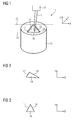
- FIG. 1 illustrates, by way of example, a device (10) according to the invention for determining the position of a jig, the jig being a pipetting needle (11) with a pipetting needle tip (12).
- the device (10) for determining the position is embedded in an analysis device (not shown in more detail), which is designed to carry out a large number of analyzes of samples.
- the automatic analyzer comprises a plurality of transport devices, not shown, as well as a control unit for the automated analysis of the analyzes.
- the device (10) for determining the position of a jig comprises a recess, which represents the receiving position (14) for the pipetting needle (11).
- the receiving position (14) has an edge (16) and a specially designed form.
- the edge (16) runs partially parallel to the imaginary lines (19, 20) and has a first edge portion (17) and a second edge portion (18).
- the pipetting needle is movable at least in the spatial directions X and Z by means of the suspension of the pipetting needle (13).
- the accommodation position (14) for the teaching is integrated in a washing station (15) for the pipetting needle (11).
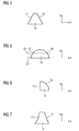
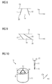
- FIG. 2 - 9 illustrate by way of example various embodiments of the shape of the edge (16) of the receiving position (14) for the teaching and preferred orientations of the receiving position (14).
- the viewing direction is along the spatial direction Z.
- FIG. 2 shows a receiving position (14) which has the shape of a triangle.
- FIG. 3 shows a receiving position (14) which has the shape of an isosceles triangle.
- FIG. 4 shows a receiving position (14), which has the shape of a corner, in the shape similar to an isosceles triangle, however, with a rounded portion between the legs.
- FIG. 5 shows a receiving position (14) which has the shape of a half-circular disk.
- the imaginary lines (19, 20) are shown.
- FIG. 6 shows a receiving position (14) which has the shape of a quarter circular disk.
- FIG. 7 shows a receiving position (14), wherein the first edge portion (17) is convexly curved, and the second edge portion (18) extends straight.
- FIG. 8th shows a receiving position (14), which by a straight first edge portion (17) and a straight second edge portion (18), which are inclined characteristically to each other, and by the imaginary lines (19, 20) is limited.
- FIG. 9 shows a receiving position (14), which by a straight first edge portion (17) and a straight second edge portion (18), which are inclined characteristically to each other, and by the imaginary lines (19, 20) is limited.
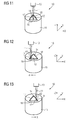
- FIG. 10-13 illustrate, by way of example, various steps of a preferred embodiment of the method according to the invention for determining the position of a jig. Some of the steps can also be performed in alternative orders.
- FIG. 10 a device (10) with a pipetting needle (11) with a pipetting needle tip (12) and a suspension (13) and a receiving position (14) with a first edge portion (17) and a second edge portion (18).
- the device (10) is integrated in a washing station (15) for the pipetting needle (11).
- the pipetting needle (11) is located outside the receiving position (14).
- FIG. 11 shows the in FIG. 10 represented objects, wherein the pipetting needle (11) is in the receiving position (14). This can be achieved by moving the pipetting needle in the spatial direction X and / or Y and Z.
- FIG. 12 shows the in FIG. 11 represented objects.
- FIG. 13 shows the in FIG. 11 represented objects.
- a second point X2 is determined by approaching and / or stopping the pipetting needle (11) against the second edge section (18).
- An exact determination of the position of the pipetting needle (11) in the spatial direction X can be made by evaluating X1 and X2.
- the distance of the points X2 and X1 is determined and allows the determination of the position of the pipetting needle (11) in the spatial direction Y by assigning the distance X1 and X2 to a position in the spatial direction Y depending on the shape and size of the receiving position (14).
Landscapes
- Engineering & Computer Science (AREA)
- Analytical Chemistry (AREA)
- General Health & Medical Sciences (AREA)
- Health & Medical Sciences (AREA)
- Life Sciences & Earth Sciences (AREA)
- Chemical & Material Sciences (AREA)
- Pathology (AREA)
- Biochemistry (AREA)
- Physics & Mathematics (AREA)
- General Physics & Mathematics (AREA)
- Immunology (AREA)
- Quality & Reliability (AREA)
- Robotics (AREA)
- Mechanical Engineering (AREA)
- Automatic Analysis And Handling Materials Therefor (AREA)
Priority Applications (1)
| Application Number | Priority Date | Filing Date | Title |
|---|---|---|---|
| EP14171722.3A EP2955526A1 (fr) | 2014-06-10 | 2014-06-10 | Dispositif de détermination de la position d'une jauge et procédé de détermination de la position |
Applications Claiming Priority (1)
| Application Number | Priority Date | Filing Date | Title |
|---|---|---|---|
| EP14171722.3A EP2955526A1 (fr) | 2014-06-10 | 2014-06-10 | Dispositif de détermination de la position d'une jauge et procédé de détermination de la position |
Publications (1)
| Publication Number | Publication Date |
|---|---|
| EP2955526A1 true EP2955526A1 (fr) | 2015-12-16 |
Family
ID=50897450
Family Applications (1)
| Application Number | Title | Priority Date | Filing Date |
|---|---|---|---|
| EP14171722.3A Withdrawn EP2955526A1 (fr) | 2014-06-10 | 2014-06-10 | Dispositif de détermination de la position d'une jauge et procédé de détermination de la position |
Country Status (1)
| Country | Link |
|---|---|
| EP (1) | EP2955526A1 (fr) |
Cited By (3)
| Publication number | Priority date | Publication date | Assignee | Title |
|---|---|---|---|---|
| CN108169502A (zh) * | 2017-12-22 | 2018-06-15 | 深圳市普康电子有限公司 | 容纳结构、收容探针的方法和生化分析仪 |
| CN111482957A (zh) * | 2019-07-12 | 2020-08-04 | 上海智殷自动化科技有限公司 | 一种视觉离线示教仪注册方法 |
| AT527699A1 (de) * | 2023-11-10 | 2025-05-15 | Meon Medical Solutions Gmbh & Co Kg | Verfahren zur Referenzierung einer Position einer Pipettiernadel und Verfahren zur Kalibrierung einer Antriebseinheit eines Analysators sowie Analysator |
Citations (5)
| Publication number | Priority date | Publication date | Assignee | Title |
|---|---|---|---|---|
| US5529754A (en) * | 1994-05-02 | 1996-06-25 | Hoffmann-La Roche Inc. | Apparatus for capacitatively determining the position of a pipetting needle within an automated analyzer |
| US20070065945A1 (en) * | 2005-09-21 | 2007-03-22 | Sigrist Rolf | Method and apparatus for positioning a pipetting device |
| US20080031774A1 (en) * | 2006-03-13 | 2008-02-07 | Sage Science, Inc. | Apparatus for Guiding Sample and Reagent Manipulations and Receptacles for Holding Same |
| DE102008058065A1 (de) | 2008-11-18 | 2010-05-20 | Diasys Diagnostic Systems Gmbh | Automatisierte Analysevorrichtung mit einer automatischen Pipettiervorrichtung und mit einer Messvorrichtung zum Bestimmen der Position der Pipettiernadelspitze |
| WO2013121680A1 (fr) * | 2012-02-15 | 2013-08-22 | 株式会社島津製作所 | Dispositif de coulée d'échantillon automatique |
-
2014
- 2014-06-10 EP EP14171722.3A patent/EP2955526A1/fr not_active Withdrawn
Patent Citations (5)
| Publication number | Priority date | Publication date | Assignee | Title |
|---|---|---|---|---|
| US5529754A (en) * | 1994-05-02 | 1996-06-25 | Hoffmann-La Roche Inc. | Apparatus for capacitatively determining the position of a pipetting needle within an automated analyzer |
| US20070065945A1 (en) * | 2005-09-21 | 2007-03-22 | Sigrist Rolf | Method and apparatus for positioning a pipetting device |
| US20080031774A1 (en) * | 2006-03-13 | 2008-02-07 | Sage Science, Inc. | Apparatus for Guiding Sample and Reagent Manipulations and Receptacles for Holding Same |
| DE102008058065A1 (de) | 2008-11-18 | 2010-05-20 | Diasys Diagnostic Systems Gmbh | Automatisierte Analysevorrichtung mit einer automatischen Pipettiervorrichtung und mit einer Messvorrichtung zum Bestimmen der Position der Pipettiernadelspitze |
| WO2013121680A1 (fr) * | 2012-02-15 | 2013-08-22 | 株式会社島津製作所 | Dispositif de coulée d'échantillon automatique |
Cited By (4)
| Publication number | Priority date | Publication date | Assignee | Title |
|---|---|---|---|---|
| CN108169502A (zh) * | 2017-12-22 | 2018-06-15 | 深圳市普康电子有限公司 | 容纳结构、收容探针的方法和生化分析仪 |
| CN111482957A (zh) * | 2019-07-12 | 2020-08-04 | 上海智殷自动化科技有限公司 | 一种视觉离线示教仪注册方法 |
| CN111482957B (zh) * | 2019-07-12 | 2020-12-29 | 上海智殷自动化科技有限公司 | 一种视觉离线示教仪注册方法 |
| AT527699A1 (de) * | 2023-11-10 | 2025-05-15 | Meon Medical Solutions Gmbh & Co Kg | Verfahren zur Referenzierung einer Position einer Pipettiernadel und Verfahren zur Kalibrierung einer Antriebseinheit eines Analysators sowie Analysator |
Similar Documents
| Publication | Publication Date | Title |
|---|---|---|
| EP3096148B1 (fr) | Dispositif de pipetage | |
| EP2977767B1 (fr) | Dispositif de détermination de position d'une jauge mobile automatique | |
| EP2698626A2 (fr) | Récipient réactionnel | |
| EP2623202B1 (fr) | Procédé destiné à chauffer un volume de liquide dans une aiguille de prélèvement par pipette chauffée, dispositif de pipetage et appareil d'analyse automatique | |
| EP3216517A1 (fr) | Procede de melange d'un liquide dans un appareil d'analyse automatique | |
| EP3118628B1 (fr) | Procede de pipetage de liquides dans un appareil d'analyse automatique | |
| EP2705929B1 (fr) | Système d'ajustement pour un système de transfert dans un système de diagnostic in vitro | |
| EP2955526A1 (fr) | Dispositif de détermination de la position d'une jauge et procédé de détermination de la position | |
| EP2350676B1 (fr) | Dispositif d'analyse automatisé présentant un dispositif automatique de prélèvement par pipette et un bras de prélèvement par pipette muni d'un détecteur d'impact | |
| EP3751289B1 (fr) | Procédé de surveillance optique d'un dosage d'un liquide à pipetter | |
| EP3196649B1 (fr) | Systeme d'ajustement | |
| EP3206036A1 (fr) | Procédé de fonctionnement d'un appareil d'analyse automatique | |
| EP3100698B1 (fr) | Dispositif d'analyse automatique comprenant un système d'élimination des déchets | |
| EP3748366B1 (fr) | Dispositif de stockage des récipients à réactifs à plusieurs niveaux | |
| EP3321689A1 (fr) | Système de pipette destiné à pipeter des liquides dans un appareil d'analyse automatique | |
| EP3173794B1 (fr) | Procede de transfert d'un volume de liquide dans un appareil d'analyse | |
| EP1367380A1 (fr) | Méthode et dispositif pour la localisation et manipulation automatique de cellules | |
| EP2710109B1 (fr) | Procédé et utilization d'un dispositif pour la détermination automatique de la position d'un microsystème pour la manipulation d'un micro-objet sphérique | |
| EP4027147B1 (fr) | Système de tri des déchets | |
| EP3097974A1 (fr) | Agitateur magnétique pour un système de diagnostic in vitro | |
| EP3922994A1 (fr) | Dispositif de traitement des récipients à réactifs à plusieurs niveaux | |
| EP1891417B1 (fr) | Dispositif et procédé de détection et d'identification de structures cibles | |
| DE102011117320A1 (de) | Vorrichtung und Verfahren zum Nachweis von in biologischen oder chemischen Proben vorliegenden Substanzen | |
| EP3418749A1 (fr) | Surveillance optique de processus de mélange | |
| EP3236268B1 (fr) | Procede de garnissage optimise d'un dispositif de reception comprenant des recipients de liquide |
Legal Events
| Date | Code | Title | Description |
|---|---|---|---|
| PUAI | Public reference made under article 153(3) epc to a published international application that has entered the european phase |
Free format text: ORIGINAL CODE: 0009012 |
|
| AK | Designated contracting states |
Kind code of ref document: A1 Designated state(s): AL AT BE BG CH CY CZ DE DK EE ES FI FR GB GR HR HU IE IS IT LI LT LU LV MC MK MT NL NO PL PT RO RS SE SI SK SM TR |
|
| AX | Request for extension of the european patent |
Extension state: BA ME |
|
| STAA | Information on the status of an ep patent application or granted ep patent |
Free format text: STATUS: THE APPLICATION IS DEEMED TO BE WITHDRAWN |
|
| 18D | Application deemed to be withdrawn |
Effective date: 20160617 |