EP2955546A2 - Maut objekterkennung in einem gnss system mit partikelfilter - Google Patents
Maut objekterkennung in einem gnss system mit partikelfilter Download PDFInfo
- Publication number
- EP2955546A2 EP2955546A2 EP15168779.5A EP15168779A EP2955546A2 EP 2955546 A2 EP2955546 A2 EP 2955546A2 EP 15168779 A EP15168779 A EP 15168779A EP 2955546 A2 EP2955546 A2 EP 2955546A2
- Authority
- EP
- European Patent Office
- Prior art keywords
- state
- vehicle
- particle
- passage
- particles
- Prior art date
- Legal status (The legal status is an assumption and is not a legal conclusion. Google has not performed a legal analysis and makes no representation as to the accuracy of the status listed.)
- Granted
Links
Images



Classifications
-
- G—PHYSICS
- G08—SIGNALLING
- G08G—TRAFFIC CONTROL SYSTEMS
- G08G1/00—Traffic control systems for road vehicles
- G08G1/01—Detecting movement of traffic to be counted or controlled
- G08G1/0104—Measuring and analyzing of parameters relative to traffic conditions
- G08G1/0108—Measuring and analyzing of parameters relative to traffic conditions based on the source of data
- G08G1/0112—Measuring and analyzing of parameters relative to traffic conditions based on the source of data from the vehicle, e.g. floating car data [FCD]
-
- G—PHYSICS
- G01—MEASURING; TESTING
- G01S—RADIO DIRECTION-FINDING; RADIO NAVIGATION; DETERMINING DISTANCE OR VELOCITY BY USE OF RADIO WAVES; LOCATING OR PRESENCE-DETECTING BY USE OF THE REFLECTION OR RERADIATION OF RADIO WAVES; ANALOGOUS ARRANGEMENTS USING OTHER WAVES
- G01S19/00—Satellite radio beacon positioning systems; Determining position, velocity or attitude using signals transmitted by such systems
- G01S19/01—Satellite radio beacon positioning systems transmitting time-stamped messages, e.g. GPS [Global Positioning System], GLONASS [Global Orbiting Navigation Satellite System] or GALILEO
- G01S19/13—Receivers
- G01S19/14—Receivers specially adapted for specific applications
-
- G—PHYSICS
- G01—MEASURING; TESTING
- G01S—RADIO DIRECTION-FINDING; RADIO NAVIGATION; DETERMINING DISTANCE OR VELOCITY BY USE OF RADIO WAVES; LOCATING OR PRESENCE-DETECTING BY USE OF THE REFLECTION OR RERADIATION OF RADIO WAVES; ANALOGOUS ARRANGEMENTS USING OTHER WAVES
- G01S19/00—Satellite radio beacon positioning systems; Determining position, velocity or attitude using signals transmitted by such systems
- G01S19/38—Determining a navigation solution using signals transmitted by a satellite radio beacon positioning system
- G01S19/39—Determining a navigation solution using signals transmitted by a satellite radio beacon positioning system the satellite radio beacon positioning system transmitting time-stamped messages, e.g. GPS [Global Positioning System], GLONASS [Global Orbiting Navigation Satellite System] or GALILEO
- G01S19/393—Trajectory determination or predictive tracking, e.g. Kalman filtering
-
- G—PHYSICS
- G01—MEASURING; TESTING
- G01S—RADIO DIRECTION-FINDING; RADIO NAVIGATION; DETERMINING DISTANCE OR VELOCITY BY USE OF RADIO WAVES; LOCATING OR PRESENCE-DETECTING BY USE OF THE REFLECTION OR RERADIATION OF RADIO WAVES; ANALOGOUS ARRANGEMENTS USING OTHER WAVES
- G01S19/00—Satellite radio beacon positioning systems; Determining position, velocity or attitude using signals transmitted by such systems
- G01S19/38—Determining a navigation solution using signals transmitted by a satellite radio beacon positioning system
- G01S19/39—Determining a navigation solution using signals transmitted by a satellite radio beacon positioning system the satellite radio beacon positioning system transmitting time-stamped messages, e.g. GPS [Global Positioning System], GLONASS [Global Orbiting Navigation Satellite System] or GALILEO
- G01S19/42—Determining position
-
- G—PHYSICS
- G07—CHECKING-DEVICES
- G07B—TICKET-ISSUING APPARATUS; FARE-REGISTERING APPARATUS; FRANKING APPARATUS
- G07B15/00—Arrangements or apparatus for collecting fares, tolls or entrance fees at one or more control points
- G07B15/06—Arrangements for road pricing or congestion charging of vehicles or vehicle users, e.g. automatic toll systems
- G07B15/063—Arrangements for road pricing or congestion charging of vehicles or vehicle users, e.g. automatic toll systems using wireless information transmission between the vehicle and a fixed station
Definitions
- the present invention concerns, according to a first aspect, a method of the type indicated by the preamble of claims 1 and 13. According to another aspect the invention concerns a system for conducting said method as indicated by the preamble of claim 14.
- GNSS Global Navigation Satellite Systems
- Satellite based road tolling systems are rapidly growing in number due to their versatility and flexibility. It allows for an advanced time/distance/place concept where policy makers can adjust prices to best fit their objectives.
- a number of distinct tolling schemes may be applied based on a combination of segment based tolling where road usage cost is derived from use of road segments; cordon based tolling where there is a cost associated with travelling into (or out from) a zone; virtual gantry based tolling where there is a fee associated with crossing a virtual tolling point; and finally distance based tolling where the fee is derived from the distance driven.
- the tolling schemes can be divided into discrete schemes (segment, cordon zone, and gantry) and continuous scheme (distance).
- Non-repudiation of the tolling statement is a very important aspect of the toll system. This includes both proving that the toll statement is genuine and proving that the system correctly identifies vehicles travelling in and out of tolling zones.
- GNSS based tolling and the system model in Fig. 1 is described by international standards. Of most relevance to this invention is ISO 17573 Electronic Fee Collection - Systems architecture for vehicle-related tolling and ISO 12855 Electronic Fee Collection - Information exchange between service provision and toll charging.
- the European Union is working towards a common European interoperable system for tolling where road users have On Board Units (OBU) and a contract with one home toll operator enabling pan-European roaming where foreign toll charges are invoiced through the home toll operator.
- OBU On Board Units
- the European Commission Decision (2009/750/EC) of 6 October 2009 on the definition of the European Electronic Toll Service and its technical elements, puts this into effect.
- a satellite based road tolling system comprises 3 main physical elements. 1) The satellites 2) vehicles equipped with OBUs observing signals from the satellites and 3) a so-called back office.
- EP 1 332 336 B1 concerns a method and a system for positioning of a moveable object. More specifically, this publication relates to a map-aided positioning system wherein map information and relative position information is combined to estimate an absolute position indication by calculating a position estimate by recursively estimating in a non-linear filtering algorithm the conditional probability density for the position.
- US20090132164 A1 teaches a reinforcement learning technique for online tuning of integration filters of navigation systems needing a priori tuning parameters, such as Kalman Filters and the like.
- the method includes receiving GNSS measurements from the GNSS unit of the navigation system; and IMU measurements from IMU of the navigation system.
- the method further includes providing a priori tuning parameters to tune the integration filter of the navigation system.
- the method further includes processing the GNSS and IMU measurements using the tuned integration filter to compute a position estimate and updating the a priori turning parameters based on the computer position estimate.
- US20130265191 describes a method of determining a geographic position of a user terminal including a receiver of signals of a global navigation satellite system, the method including the user terminal: performing pseudo-range measurements related to a plurality of signals received from transmitters of the global navigation satellite system; calculating a first estimated position thereof by a weighted least squares method; calculating post-fit residuals for the first estimated position; comparing the calculated post-fit residuals to a first threshold and: in case the first threshold is exceeded, calculating a second estimated position using a Monte-Carlo method, otherwise retaining the first estimated position as the geographic position of the mobile communications terminal.
- US7324017B2 concerns a process for determining travel through at least one toll road section by at least one vehicle by means of a position determination system which is set up to determine the current position of the at least one vehicle, whereby positions of the at least one vehicle are compared with the position of at least one reference point characteristic for an entrance to a toll road section, whereby the orientation of the vehicle is determined within a specifiable region about the entrance, whereby it is determined whether the orientation determined agrees within a specifiable tolerance range with the orientation characteristic of entry onto the toll road section.
- EP2230644A1 describes a method which involves maintaining global positioning systems of vehicles in standby. Positioning functions of the global positioning systems are stimulated at the proximity of geographical positioning points e.g. taxation points, where the stimulation of the positioning function of each global positioning system is calculated from an origin positioning instant, near geographical positioning point and maximum speed of the vehicles.
- geographical positioning points e.g. taxation points
- WO 2012/130889 teaches a positioning system comprising at least one GNSS satellite receiver which is located in a mobile element belonging to a user and which is used to estimate the position of the mobile element at different points in time.
- a first processing module determines a coherence indicator by combining the estimated positions and data supplied by secondary information sources.
- a dynamic model for moving the mobile element is used. The indicator is determined by comparing speed, acceleration, gyration triplet, to a dynamic model for moving an object, vehicle, person or the like.
- the system further comprises a consolidation module included means for storing the positions estimated at different moments and a digital filter can be used to obtain a filtered position from the stored positions, the coherence indicator being calculated from the filtered positions.
- the system also comprises detection means for determining, on the basis of the coherence indicator, whether or not the estimated positions have been falsified.
- the object of the present invention is to provide a method and a system which with simple and inexpensive means improves the reliability of satellite based tolling systems, increasing the confidence and robustness of such methods and systems.
- the present invention may also be used for related purposes in non-tolling applications.
- the present invention concerns a system as defined by claim 14 arranged to conduct said method.
- a passage detection method based on Sequential Monte Carlo method is applied to the domain of identifying passages by a vehicle through a tolling object utilizing GNSS systems.
- Sequential Monte Carlo method also known as particle filter
- passage detection simply uses information from a GNSS-based position system and subsequently use the estimated position and the associated and often poorly estimated error estimates from the system as a basis for its passage assessment.
- the present invention unifies these two methods in an integrated method. This unification allows the passage detection to base its decisions on a much larger set of information. At the same time, the passage detection will result in an estimated probability distribution that closely represents the true probability. This allows the system to select an arbitrary confidence margin and only issue toll transactions when the required confidence level is met.
- vehicle is to be interpreted in the broadest sense possible, not only covering automobiles and the like.
- the method and system according to the present invention is discussed in terms of a method and system for assessment of vehicles passing into and out from a certain zone, passage of a certain virtual gantry, passage of a certain road segment, and assessing distance driven by vehicles. It should be emphasized that the method and system as such, while suited for such a purpose, is a general system for detection of objects passing into and out from a zone, or passage of check points (virtual gantries), etc., irrespective of the subsequent use of said information.
- the elements encountered in a GNSS tolling system 10 illustrated in Fig. 1 are a GNSS satellite 11, an OBU 12, a proxy 13 and a back office 14. There is a first exchange of data communication 15 between the OBU and the proxy, and a second exchange of data communication 16 between the proxy 13 and a back office 14. There is no limitation with regard to the technology involved with the exchange of information between the different units. There is not necessarily a one-to-one relation between the shown elements; there will e.g. typically be a number of satellites 11 disseminating information enabling the localization of the OBU at any given point in time. All calculations made and/or conclusions drawn with regard to assessment of passages may be performed either locally, like in the individual OBUs, centrally in a back office or by a proxy or in any other combination found convenient therefore.
- FIG. 2 illustrates the main components of the OBU 12.
- the OBU includes a volatile memory 21, a GNSS receiver 22, a processing unit 23, a communication unit 24 and persistent storage 25.
- the OBU may be a physical device dedicated to the GNSS tolling system, but it may also be present as a function integrated in other devices fit for the purpose, such as a tachograph or other device, portable, mounted in, or integrated in the vehicle.
- the GNSS module 10 may be implemented with different levels of sophistication, ranging from a simple GPS receiver to a complex navigation unit using information from multiple GNSS systems, motion sensors with vehicle instruments and sensors. It is the particular method as described below that constitutes the present invention.
- Figure 3 illustrates the earth with two different coordinate systems and four GNSS satellites. Coordinates for use by the method and system of the present invention may according to a preferred embodiment be expressed in Earth-Centred Earth-Fixed (ECEF), a 3 dimensional orthogonal coordinate system (X,Y,Z). Origin of the ECEF system is formed by the centre of mass of the earth. ECEF is thus the natural coordinate system for satellite orbital calculations. For referencing locations on earth the World Geodetic System (WGS84) is more convenient. This is based on an ellipsoid approximating the earth. ECEF coordinates may be transformed to longitude, latitude, and ellipsoid height ( ⁇ , ⁇ ,h). Furthermore, ellipsoid height may be translated to height above mean sea level by applying geoid separation information.
- ECEF Earth-Centred Earth-Fixed
- X,Y,Z 3 dimensional orthogonal coordinate system
- Origin of the ECEF system is formed by the centre of
- the figure also shows GNSS space vehicles (SV 1 , SV 2 , SV 3 , and SV 4 ) with pseudo ranges from an observation point on earth to each space vehicle.
- GNSS space vehicles SV 1 , SV 2 , SV 3 , and SV 4
- Figure 4 shows how the distance between the OBU (observation point) and the space vehicle is measured.
- the measurement is called pseudo range.
- the measurement differs from the true range by an aggregation of multiple error sources.
- Pseudo range is calculated by multiplying speed of light (c 0 ) with the measured propagation time.
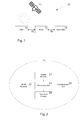
- Figure 5a shows the general steps involved in the method according to the present invention.
- a first step 50 an initial position for a vehicle is established by any convenient method.
- a chosen number of particles are generated according to the principles of the Sequential Monte Carlo method.
- a prediction of the state variables of each particle is made according to a process model to be further elaborated below.
- the probabilities or "weights" of the particles are updated in a step 53, optionally involving measurement of additional properties related to the vehicles.
- step 54 passage or non-passage is evaluated and assessed based on either individual particles or on the probability distribution.
- Steps 52 - 56 are operating recursively.
- the final step 57 of Figure 5 is the issuance of a toll transaction when the evaluation step 54 so decides.
- the weights represent a probability after having been subjected to a suitable scaling factor.
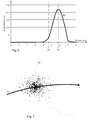
- Figure 5b shows details of step 54 in the method according to the present invention.
- an initial step 5400 the probability distribution is examined to assess if the filter is inconclusive a possible position estimate ambiguity exists. If such ambiguity exist the method proceeds to step 5431 and no further processing takes place, which in practice means that the step of assessing passage or non-passage is concluded in the negative if a position ambiguity is detected.
- the steps 5410, 5411, 5412 and 5413 illustrates the method where VG, zone, and segment passage detection is performed on each particle in step 5410, in step 5420 the number of particles where a passage is detected is counted while taking weights into account, resulting in a ration of passages over total particles.
- Step 5412 compares this ratio to a defined confidence limit and if the ratio is above the limit, passage or non-passage is assessed in step 5413.
- the steps 5420, 5421, 5422, and 5423 illustrates the method where first a state vector is estimated in step 5420 by calculation of average or median over all particles to get a position estimate, variance is also calculated, in step 5421 the variance is tested against a defined limit and if the variance is too high, the method proceeds to step 5432 and no further processing takes place. If the variance is found to be adequate for tolling; VG, zone, and segment passage detection is performed on the position estimate in step 5422, passage or non-passage is assessed in step 5423.
- the probability of passage of a tolling object selected from the group consisting of a Virtual Gantry (VG), a zone, and a segment can be calculated individually for each particle and the probability for the vehicle actually passing the VG, the zone or the segment from the ratio of particles having passed through the VG, the zone or the segment, when the ratio is above a defined confidence limit.
- VG Virtual Gantry
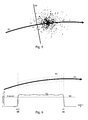
- Figure 6 shows the probability distribution 63 of distances measured by a number of particles in the Particle filter ensemble.
- the average of the distances, in this example, is 5.8 km (right dashed vertical line 62).
- the system may select a confidence level of e.g. 2% (in this example) and conclude that the distance travelled by the vehicle is less than 5.1 km (left dashed vertical line 61) with 98% confidence.
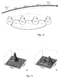
- Figure 7 shows a particle cloud representing an ensemble of particles for a vehicle close to a zone border.
- the zone is shown as a closed polygon 72.
- Each black dot represents a particle with a specific weight, larger circles have larger weight.
- Black arrow 71 indicates vehicle trajectory.
- Figure 8 shows a particle cloud representing an ensemble of particles for a vehicle close to a virtual gantry.
- Black arrow 81 indicates vehicle trajectory (road).
- the virtual gantry charging point is shown as a line 82 crossing the road.
- Each black dot represents a particle with a specific weight, larger circles have larger weight.
- Figure 9 shows a road 91 with a particular road segment enclosed by a polygon 92. It illustrates a method for detecting vehicles driving on the road segment to allow charging the road user for its use.
- a graph 93 showing the probability of the vehicle driving on that particular road segment as a function of actual position. The probability may be calculated at each epoch from the particle ensemble by calculating the ratio of particles inside and outside, accounting for the weights. The ratio corresponds to the probability of the vehicle being inside the segment at that epoch. Repeating the process for each epoch will create the graph.
- a threshold 94 an assessment of the road segment passage and the associated enter 95 and exit 96 events can be made.
- the segment may be defined as a 2 or 3-dimensional object similar to the zone definition.
- Figure 10 shows a road where three adjacent non-overlapping polygons are created, enclosing a road section. Each polygon represents a transient state while driving on the road.
- a state diagram representing the above transition state matrix is shown.
- a vehicle driving on the road in the direction of the arrows will pass through states 0, 1, 2, 3, and 0 in that order, shown as bold arrows in the state diagram.
- Positioning is based on measuring time differences between send time at the satellites and reception time at the receiver. This time difference has two components: actual propagation time ⁇ t, and receiver clock bias ⁇ t, as illustrated in Fig. 4 .
- the receiver clock bias will be common in all observed pseudoranges in one navigation system.
- the pseudo range may be calculated.
- Tropospheric delay is related to chemical composition of the troposphere and the path length the signal is travelling. Zenith path delay is the delay when the signal is travelling the shortest possible path.
- the pseudo range is different from the true range because of contributions from many sources of error such as small deviations in the orbit of satellites, code lock quantification, reflection of signal from near-by buildings or mountains, clock errors, troposphere and ionosphere properties, etc. Some of these error factors are of a seemingly stochastic nature, while other factors are more correlated in time, at least within a certain period of time. Other error factors may be more dependent on local topographical elements, such as errors caused by reflection of signals from terrain or nearby structures like buildings.
- the dynamic system of the moving vehicle is described by a process model that describes how the state variable evolves over time, and a measurement model that describes how the measurements relate to the state vector and the process model.
- x t x t ⁇ x ⁇ t ⁇ y t ⁇ y ⁇ t ⁇ z t ⁇ z ⁇ t ⁇ g t ⁇ g ⁇ t ⁇ zpd t
- x, y, z coordinates in ECEF
- ⁇ , ⁇ , ⁇ are the first derivate of position, i.e. velocity
- g clock bias in the receiver
- ⁇ is the first derivate of the clock bias
- zpd is the zenith path delay.
- the measurement model in the Particle filter may be arbitrary complex, the only requirements is that it is computable, whereas in a Kalman filter model it must be linear.
- a receiver will decode and use signal from at least four satellites to calculate both a position estimate and the receiver clock bias.
- the receiver will apply estimation algorithms to find the optimal solution to the problem using information collected over some period of time and from all available sources (satellites).
- sources such as a typical outdoor environment, about 10 GPS and 8 GLONASS satellites are within view (at the time of this writing), but it is expected that the European Galileo and Chinese Beidou deployment programmes will increase the number of visible satellites to 40 within 2020.
- the position estimate have been calculated using a Kalman filter (or variations thereof, such as the Extended Kalman filter).
- the simplest form of the Kalman filter assumes that the error terms are Gaussian distributed and independent, and that the process model is linear.
- the Kalman filter can be shown to create a statistically optimal position solution if the assumptions for the application of Kalman filter are fulfilled.
- One way to get a linear process model is to linearize around a specific state (i.e. coordinate). If the a-priori estimated state is offset from the true state, the linearization may produce significant errors in the propagation of the covariance information and thus the position estimates.
- non-Gaussian, or time dependant errors may also affect the performance of the Kalman filter.
- Errors originating in the atmosphere and space segment will often create errors that are slowly varying and thus non-Gaussian. Additionally, long tails (outliers) are not taken into account by the Gaussian approximation. The model mismatch will also cause the state variable covariance matrix to be difficult to interpret, making it difficult to make an assessment of the error in the estimated position.
- the Particle filter is also known as Sequential Monte Carlo method.
- the filter consists, as the Kalman filter, of a prediction step and a subsequent update step. Let there be B particles in the Particle filter.
- ⁇ t b is a process noise term.
- the prediction step gives samples that together represent the distribution of the state vector x t given all previous measurements z t ⁇ ⁇ x t
- This probability distribution (represented by the B particles) is then updated by conditioning on the last measurement z t to ⁇ x t
- the Particle filter has fewer limitations than the Kalman filter. There is no assumption about a linear process model, and it is possible to use any model for the process and measurement noise.
- the Kalman filter may be regarded as a special case of a Particle filter, if the process model is linear and the noise is Gaussian, the Particle filter and the Kalman filter will find the same solution.
- the objective of the Particle filter is to estimate the probability density function for all state variables given the measurements, whereas the Kalman filter only estimates the state variables mean value and the covariance matrix from where standard deviations may be derived. This is because the Kalman filter assumes Gaussianity, in which the distribution is completely specified by its mean vector and covariance matrix.
- the Particle filter is described by a process model, and a measurement model, similar to what is known from the Kalman filter, except that both may be non-linear.
- a large ensemble of particles is created by using a-priori information, giving each particle equal probability (or weight).
- Each particle has its own state vector.
- Initial position information may be calculated from the GNSS pseudo ranges by applying a traditional Kalman filter or other estimation methods, also non-GNSS methods such as crude position estimates from mobile network measurements may be used.
- a first position estimate may also be to use the last known position.
- One advantage of the Particle filter is that the possibility to simple adaptation to non-Gaussian measurement errors agree well with the error characteristics of GNSS pseudo range measurements, i.e. they have larger occurrences of outliers layers, that are highly correlated in time.
- Additional measurement models may be based on accelerometers, turn rate gyroscopes, vehicle wheel speed, barometric pressure sensors, magnetic compass, and other physical in-vehicle measurements.
- Vehicle heading change can be deduced from wheel speed sensors detecting the wheel speed of two wheels at each end of a wheel axis, preferably a non-steering axis as well as steering wheel angle sensors.
- the process model is applied and noise is added, to prepare the particles for the next epoch.
- the particles' weights are updated according to how well their values from the prediction step agree with the measurements.
- the particles are then drawn randomly with replacement and according to probabilities proportional to the particles' weights. This is called the update step.
- Some particles will be drawn multiple times and some will not be drawn.
- the task of drawing state variables from a multidimensional state variable space may be computationally expensive. Multiple methods have been developed to make more efficient use of available computing resources.
- the Rao-Blackwellized optimization method may be used to exploit any linear Gaussian sub-structure present in the model and process that by a conventional Kalman filter.
- the paper of Capoutheastern et al. shows the actual execution steps of the Particle filter in detail.
- z 0: t ), is typically calculated by applying the weights to get an weighted average value. They can therefore be used directly in the tolling decisions. For example, the distance driven can be computed from the sum of the increments of the sequence of ( x ⁇ , ⁇ , ⁇ ).
- Fig. 11 shows a situation where the filter is inconclusive.
- Fig. 11b shows a situation where the probability distribution has two peaks, and the method can deduce that the position estimate is inconclusive and no tolling decisions should be attempted.
- Fig. 11a shows a situation where there is no such position ambiguity. Examining the probability distribution will reveal more information about the position estimate quality than simple variance VAR ( x t
- the particle ensemble may be used for tolling purposes in distance based tolling schemes.
- the distance may be calculated for each individual particle, and this will result in a collection of different distances with weights. This will represent the probability distribution of the distances and may be plotted as illustrated in Fig. 6 .
- the peak of the distribution will be close to the median or average distance.
- a confidence level of e.g. 98% may be selected and the distance calculated from that. In this way, only 2% of road users will be overcharged and 98% will be charged for less than the actual driven distance. If the distribution has no significant peak or multiple peaks, this indicates that the distance calculation has high uncertainty and no charge should be calculated.
- the zone detection may be performed for each individual particle, i.e. the inside/outside zone property is part of the state vector.
- the zone passage decision all particles are examined and the ratio of particles inside vs. outside is calculated, accounting for weights. If the ratio is above a specified limit, the zone event is assessed. If the limit is set to e.g. 98% this means that 2% false positives will be charged.
- Fig 7 shows a particle cloud entering into a zone. The actual method used to detect zone border crossing is outside the scope of this invention.
- the gantry detection may be performed on each individual particle, i.e. the passage of the gantry is part of the state vector. After each prediction and update iteration, all particles are examined and the ratio of particles passed is calculated, accounting for weights. If the ratio is above a specific limit, the virtual gantry passage event is assessed.
- Fig. 8 shows a particle cloud passing a virtual gantry. The actual method used to detect virtual gantry passage is outside the scope of this invention.
- the segment detection may be performed on each individual particle, i.e. the on/off road segment property is part of the state vector.
- a segment in this context may be regarded as a specialization of zone where the polygon describing the zone circumscribes the road, with some tolerance, creating a tolling corridor.
- the process model More likely to proceed in forward direction, less likely to turn sharply to left or right, etc.
- the particles inside vs. outside the corridor are counted. If the ratio exceeds a specific limit, the vehicle is considered to be on the road segment.
- Fig. 9 illustrates the road with a polygon enclosing a road segment and a graph showing the ratio.
- a further generalisation is to divide a road segment or virtual gantry approach into several adjacent non-overlapping polygons, where each polygon corresponds to a state as illustrated in Fig. 10 , where the discrete state variable S t may take the values 0 (outside), 1,..., n S (inside).
- n S is the number of states describing a segment.
- a successful passage corresponds with a transition from state 0 to 1, state 1 to 2, state 2 to 3, and state 3 to 0.
- a detour from state 0 to 1, state 1 to 2, state 2 to 1, state 1 to 2, state 2 to 3 and state 3 to 0 is also valid.
- the object may be in each state more than one epoch, for example if driving slowly or if the polygons are large.
- the sum of each row is 1.
- p i,j 0 if i, j > 0 and
- P can be estimated from historical data which includes the low-end GNSS receiver and a high-end reference. p 0,0 , the probability of remaining outside, will then typically be quite high. The method will therefore be on the conservative side, and not declare that the tolling object has been entered before it is very certain. This can be alleviated by having local transition matrices P around each tolling object.
- the error term ⁇ t is usually assumed to be Gaussian and independent from one epoch to the next.
- the refinements 1) and 2) can easily be combined within the Particle filter.
- a typical use of the method and system herein described would, as already mentioned, be for invoicing road-users according to any one of a number of principles, such as passage of a virtual gantry, distance driven along a certain road or the like. For this purpose any assessment of passage concluded as occurred, typically is at least temporarily stored for further use.
- Obtaining a value for initial vehicle position typically involves utilization of a priori information, selected from a) last known position with a corresponding high uncertainty, b) estimating a position from pseudo ranges using traditional methods, and c) estimating by using information from mobile phone networks.
- the tolling objects of the present invention are typically defined as spatial objects selected among 2 dimensional objects defined by latitude and longitude and 3 dimensional objects, wherein the 3 dimensional tolling objects would typically be defined in Earth Centred Earth Fixed coordinate systems. For many scenarios, 2 dimensional objects will suffice, but in some cases where roads pass each other on multiple levels, height information may be required.
- the passage detection may be performed in Earth Centred Earth Fixed coordinate system, in the latitude, longitude domain, or in any other suitable coordinate system.
- assessment of passage or non-passage is derived from the probability distribution ⁇ ( x t
- the assessment of passage can preferably in addition be based on the derived probability distribution ⁇ ( x t
- the method described above will detect the same toll object multiple times, even if the vehicle has made only one actual passage. Traditionally this has been corrected by post processing the events from the OBU in the back-office.
- a separate discrete state variable may be introduced to the state vector to indicate if a tolling object has been charged for or not. This can be achieved by a separate Markov transition matrix for the charging decision.
- the transition probability from charging to non-charging can then for example, be equal to 1 for a desired number of seconds or for a desired spatial position offset, before it is lowered to a lower probability again. This will increase the confidence in the charging decision and can eliminate "double charging" events.
- the method may operate in time delayed mode, and base its decisions on both a-priori and a-posterior information. If the method can relax its real-time requirements and is allowed to make its passage assessments in retrospect, it will increase the confidence in the passage assessments.
- the delay may be expressed as a number of seconds or as a distance. E.g. the virtual gantry passage assessment is only made 10 seconds after the first indication of a passage. This can also be combined with a backwards smoothing filter, which means that we compute: ⁇ ⁇ x t - k
- the process model used in the Particle filter can be extended to use additional measurements, like vehicle speed, heading and height. This can be done by adding new states to the state vector x t , as well as updating the system and measurement process equations ⁇ t and h t .
- the non-linearities arising from the additional sensors in these functions are handled by the Particle filter.
- Many types of sensors may be used to measure this including wheel speed sensors, magnetometer, radar, imaging systems, barometric air pressure sensor, etc. Wheel speed may be measured individually on each wheel leading to indirect measurement of turn rate.
- Small and inexpensive sensors based on micro-electromechanical systems (MEMS) technology may be used to measure acceleration and rotations in 3 dimensions.
- MEMS micro-electromechanical systems
- the measurement model for vehicle movement measurement sensors is relatively complex and non-linear due to the transformation from sensor frame to body (vehicle frame) and to ECEF.
- the details of this transformation is well known and outside the scope of this invention. Additional independent sensors will in general increase the robustness of the estimation and thus the method performance. It is thus preferred, as indicated above, to combine use of GNSS pseudo range measurements with use of at least one sensor selected among accelerometers, gyroscopes, vehicle wheel speed sensors, barometric pressure sensors, and magnetic compasses.
- a digital map may be used to limit the space of possible system states to legal drives on known roads. The use of a map is outside the scope of this invention.
Landscapes
- Engineering & Computer Science (AREA)
- Radar, Positioning & Navigation (AREA)
- Remote Sensing (AREA)
- Physics & Mathematics (AREA)
- General Physics & Mathematics (AREA)
- Computer Networks & Wireless Communication (AREA)
- Business, Economics & Management (AREA)
- Finance (AREA)
- Chemical & Material Sciences (AREA)
- Analytical Chemistry (AREA)
- Navigation (AREA)
- Devices For Checking Fares Or Tickets At Control Points (AREA)
- Radar Systems Or Details Thereof (AREA)
- Traffic Control Systems (AREA)
- Measurement Of Radiation (AREA)
- Electron Tubes For Measurement (AREA)
Priority Applications (1)
| Application Number | Priority Date | Filing Date | Title |
|---|---|---|---|
| EP19179568.1A EP3575833A1 (de) | 2014-06-03 | 2015-05-21 | Entfernungsmessung in einem gnss-system mithilfe eines partikelfilters |
Applications Claiming Priority (1)
| Application Number | Priority Date | Filing Date | Title |
|---|---|---|---|
| NO20140686A NO337304B1 (no) | 2014-06-03 | 2014-06-03 | Påvisning av et avgiftsobjekt i et GNSS-system med partikkelfilter |
Related Child Applications (2)
| Application Number | Title | Priority Date | Filing Date |
|---|---|---|---|
| EP19179568.1A Division EP3575833A1 (de) | 2014-06-03 | 2015-05-21 | Entfernungsmessung in einem gnss-system mithilfe eines partikelfilters |
| EP19179568.1A Division-Into EP3575833A1 (de) | 2014-06-03 | 2015-05-21 | Entfernungsmessung in einem gnss-system mithilfe eines partikelfilters |
Publications (3)
| Publication Number | Publication Date |
|---|---|
| EP2955546A2 true EP2955546A2 (de) | 2015-12-16 |
| EP2955546A3 EP2955546A3 (de) | 2016-05-11 |
| EP2955546B1 EP2955546B1 (de) | 2019-07-31 |
Family
ID=53264500
Family Applications (2)
| Application Number | Title | Priority Date | Filing Date |
|---|---|---|---|
| EP15168779.5A Active EP2955546B1 (de) | 2014-06-03 | 2015-05-21 | Maut objekterkennung in einem gnss system mit partikelfilter |
| EP19179568.1A Pending EP3575833A1 (de) | 2014-06-03 | 2015-05-21 | Entfernungsmessung in einem gnss-system mithilfe eines partikelfilters |
Family Applications After (1)
| Application Number | Title | Priority Date | Filing Date |
|---|---|---|---|
| EP19179568.1A Pending EP3575833A1 (de) | 2014-06-03 | 2015-05-21 | Entfernungsmessung in einem gnss-system mithilfe eines partikelfilters |
Country Status (4)
| Country | Link |
|---|---|
| US (1) | US9886849B2 (de) |
| EP (2) | EP2955546B1 (de) |
| NO (1) | NO337304B1 (de) |
| WO (1) | WO2015187029A1 (de) |
Cited By (2)
| Publication number | Priority date | Publication date | Assignee | Title |
|---|---|---|---|---|
| CN110035024A (zh) * | 2019-03-31 | 2019-07-19 | 华南理工大学 | 一种基于确定性序贯蒙特卡罗算法的软解调方法及装置 |
| DE102019200147A1 (de) | 2019-01-08 | 2020-07-09 | Robert Bosch Gmbh | Verfahren und Vorrichtung zum Bereitstellen von Ground-Truth-Daten |
Families Citing this family (15)
| Publication number | Priority date | Publication date | Assignee | Title |
|---|---|---|---|---|
| US20140278838A1 (en) * | 2013-03-14 | 2014-09-18 | Uber Technologies, Inc. | Determining an amount for a toll based on location data points provided by a computing device |
| JP6295122B2 (ja) * | 2014-03-27 | 2018-03-14 | 株式会社メガチップス | 状態推定装置、プログラムおよび集積回路 |
| CN107872055A (zh) * | 2016-09-28 | 2018-04-03 | 北京南瑞电研华源电力技术有限公司 | 电网安全运行通信设备传输数据不确定度评定方法及装置 |
| US11604287B2 (en) | 2018-08-09 | 2023-03-14 | Apple Inc. | Machine learning assisted satellite based positioning |
| US11474486B2 (en) * | 2019-03-11 | 2022-10-18 | Mitsubishi Electric Research Laboratories, Inc. | Model-based control with uncertain motion model |
| WO2020237077A1 (en) * | 2019-05-22 | 2020-11-26 | Ohio State Innovation Foundation | Closed loop adaptive particle forecasting |
| KR20210070515A (ko) * | 2019-12-05 | 2021-06-15 | 현대자동차주식회사 | 주행 차선 유지 제어 시스템 및 그의 주행 차선 유지 제어 방법 |
| WO2021236454A1 (en) * | 2020-05-22 | 2021-11-25 | The Board Of Regents Of The University Of Oklahoma | Multi-inertial measurement unit fusion for fine-resolution position estimation |
| CN112762928B (zh) * | 2020-12-23 | 2022-07-15 | 重庆邮电大学 | 含有激光slam的odom与dm地标组合移动机器人及导航方法 |
| CN113465620A (zh) * | 2021-06-02 | 2021-10-01 | 上海追势科技有限公司 | 一种基于语义信息的停车场粒子滤波定位方法 |
| GB202111274D0 (en) | 2021-08-04 | 2021-09-15 | Q Free Norge As | Vehicle movement tracking |
| CN115862362B (zh) * | 2021-09-23 | 2025-04-29 | 中移(上海)信息通信科技有限公司 | 车辆位置显示方法、系统、装置及云控平台 |
| CN116879946B (zh) * | 2023-07-04 | 2024-01-30 | 成都理工大学 | 基于多目标蜉蝣算法改进粒子滤波算法的叠前反演方法 |
| CN117473717B (zh) * | 2023-10-19 | 2024-12-06 | 同济大学 | 一种基于Bernoulli-Gaussian模型和EM算法的数据质量分析方法 |
| CN117213501B (zh) * | 2023-11-09 | 2024-02-02 | 成都工业职业技术学院 | 一种基于分布式模型预测的机器人避障规划方法 |
Citations (7)
| Publication number | Priority date | Publication date | Assignee | Title |
|---|---|---|---|---|
| WO2002039063A1 (en) | 2000-11-08 | 2002-05-16 | Nira Dynamics Ab | Map-aided positioning |
| EP1811480A1 (de) | 2006-01-18 | 2007-07-25 | GMV Aerospace and Defence S.A. | Automatisches Streckenberechnungssystem auf ausschließlicher Satellitennavigationsbasis unter Berücksichtigung des Positionsfehlers und Verfahren dazu |
| US7324017B2 (en) | 2002-09-12 | 2008-01-29 | Siemens Ag Osterreich | Method for identifying a toll-required section of road |
| US20090132164A1 (en) | 2007-10-04 | 2009-05-21 | Goodall Chris | System and method for intelligent turning of kalman filters for ins/gps navigation applications |
| EP2230644A1 (de) | 2009-03-20 | 2010-09-22 | CS Systemes d'Informations | Verfahren und System zur Ortung von Landfahrzeugen in einem Straßennetz, Gehäuse für die Satellitenlokalisierung für dieses Verfahren und dieses System |
| WO2012130889A1 (fr) | 2011-03-31 | 2012-10-04 | Thales | Systeme de positionnement avec mecanisme de detection de fraude pour application critique |
| US20130265191A1 (en) | 2010-12-13 | 2013-10-10 | Telecom Italia S.P.A. | Method and system for localizing mobile communications terminals |
Family Cites Families (14)
| Publication number | Priority date | Publication date | Assignee | Title |
|---|---|---|---|---|
| US5323322A (en) * | 1992-03-05 | 1994-06-21 | Trimble Navigation Limited | Networked differential GPS system |
| JP3352054B2 (ja) * | 1999-06-15 | 2002-12-03 | トヨタ自動車株式会社 | 移動体用課金処理装置 |
| WO2004059900A2 (en) * | 2002-12-17 | 2004-07-15 | Evolution Robotics, Inc. | Systems and methods for visual simultaneous localization and mapping |
| US20070218931A1 (en) * | 2006-03-20 | 2007-09-20 | Harris Corporation | Time/frequency recovery of a communication signal in a multi-beam configuration using a kinematic-based kalman filter and providing a pseudo-ranging feature |
| US20090157566A1 (en) * | 2006-03-21 | 2009-06-18 | Bernard Grush | Method and process to ensure that a vehicular travel path recording that includes positional errors can be used to determine a reliable and repeatable road user charge |
| US8384560B2 (en) * | 2008-03-11 | 2013-02-26 | Kapsch Trafficcom Ivhs Inc. | Real-time vehicle position determination using communications with variable latency |
| GB201010180D0 (en) * | 2010-06-17 | 2010-07-21 | Skymeter Corp | Tracking method |
| EP2519803B1 (de) * | 2010-11-08 | 2014-01-15 | Elektrobit Automotive GmbH | Verfahren zur kalibrierung von koppelnavigationspositionierungsdaten |
| US9562965B2 (en) * | 2011-05-04 | 2017-02-07 | Jacques Georgy | Two-stage filtering based method for multiple target tracking |
| US8909586B2 (en) * | 2012-09-12 | 2014-12-09 | Numerica Corp. | Method and system for determining a track of an object through a multi-dimensional space |
| WO2014054044A1 (en) * | 2012-10-04 | 2014-04-10 | Ramot At Tel-Aviv University Ltd. | Method and system for estimating position |
| KR20150058679A (ko) * | 2013-11-20 | 2015-05-29 | 한국전자통신연구원 | 단지내 도로에서 자율주행차량의 위치 및 해딩 정보 제공 장치 및 방법 |
| US20150219767A1 (en) * | 2014-02-03 | 2015-08-06 | Board Of Regents, The University Of Texas System | System and method for using global navigation satellite system (gnss) navigation and visual navigation to recover absolute position and attitude without any prior association of visual features with known coordinates |
| US9460429B2 (en) * | 2014-08-19 | 2016-10-04 | iDiggApp Inc. | GPS-based toll collection system and method |
-
2014
- 2014-06-03 NO NO20140686A patent/NO337304B1/no unknown
-
2015
- 2015-05-21 WO PCT/NO2015/050088 patent/WO2015187029A1/en not_active Ceased
- 2015-05-21 EP EP15168779.5A patent/EP2955546B1/de active Active
- 2015-05-21 EP EP19179568.1A patent/EP3575833A1/de active Pending
- 2015-06-01 US US14/726,654 patent/US9886849B2/en active Active
Patent Citations (8)
| Publication number | Priority date | Publication date | Assignee | Title |
|---|---|---|---|---|
| WO2002039063A1 (en) | 2000-11-08 | 2002-05-16 | Nira Dynamics Ab | Map-aided positioning |
| EP1332336B1 (de) | 2000-11-08 | 2012-10-17 | Nira Dynamics AB | Kartenunterstützte positionierung |
| US7324017B2 (en) | 2002-09-12 | 2008-01-29 | Siemens Ag Osterreich | Method for identifying a toll-required section of road |
| EP1811480A1 (de) | 2006-01-18 | 2007-07-25 | GMV Aerospace and Defence S.A. | Automatisches Streckenberechnungssystem auf ausschließlicher Satellitennavigationsbasis unter Berücksichtigung des Positionsfehlers und Verfahren dazu |
| US20090132164A1 (en) | 2007-10-04 | 2009-05-21 | Goodall Chris | System and method for intelligent turning of kalman filters for ins/gps navigation applications |
| EP2230644A1 (de) | 2009-03-20 | 2010-09-22 | CS Systemes d'Informations | Verfahren und System zur Ortung von Landfahrzeugen in einem Straßennetz, Gehäuse für die Satellitenlokalisierung für dieses Verfahren und dieses System |
| US20130265191A1 (en) | 2010-12-13 | 2013-10-10 | Telecom Italia S.P.A. | Method and system for localizing mobile communications terminals |
| WO2012130889A1 (fr) | 2011-03-31 | 2012-10-04 | Thales | Systeme de positionnement avec mecanisme de detection de fraude pour application critique |
Non-Patent Citations (2)
| Title |
|---|
| FREDRIK GUSTAFSSON; FREDRIK GUNNARSSON; NICLAS BERGMAN; URBAN FORSSELL; JONAS JANSSON; RICKARD KARLSSON; PER-JOHAN NORDLUND: "Particle Filters for Positioning, Navigation and Tracking", IEEE TRANSACTIONS ON SIGNAL PROCESSING, SPECIAL ISSUE ON MONTE CARLO METHODS FOR STATISTICAL SIGNAL PROCESSING, February 2002 (2002-02-01) |
| OLIVIER CAPPE; SIMON J. GODSILL; ERIC MOULINES: "An Overview of Existing Methods and Recent Advances in Sequential Monte Carlo", PROCEEDINGS OF THE IEEE, vol. 95, no. 5, 2007 |
Cited By (3)
| Publication number | Priority date | Publication date | Assignee | Title |
|---|---|---|---|---|
| DE102019200147A1 (de) | 2019-01-08 | 2020-07-09 | Robert Bosch Gmbh | Verfahren und Vorrichtung zum Bereitstellen von Ground-Truth-Daten |
| CN110035024A (zh) * | 2019-03-31 | 2019-07-19 | 华南理工大学 | 一种基于确定性序贯蒙特卡罗算法的软解调方法及装置 |
| CN110035024B (zh) * | 2019-03-31 | 2021-10-26 | 华南理工大学 | 一种基于确定性序贯蒙特卡罗算法的软解调方法及装置 |
Also Published As
| Publication number | Publication date |
|---|---|
| US20150348409A1 (en) | 2015-12-03 |
| NO337304B1 (no) | 2016-03-07 |
| WO2015187029A1 (en) | 2015-12-10 |
| EP3575833A1 (de) | 2019-12-04 |
| EP2955546A3 (de) | 2016-05-11 |
| NO20140686A1 (no) | 2015-12-04 |
| EP2955546B1 (de) | 2019-07-31 |
| US9886849B2 (en) | 2018-02-06 |
Similar Documents
| Publication | Publication Date | Title |
|---|---|---|
| EP2955546B1 (de) | Maut objekterkennung in einem gnss system mit partikelfilter | |
| US10018729B2 (en) | Selected aspects of advanced receiver autonomous integrity monitoring application to kalman filter based navigation filter | |
| El‐Mowafy et al. | Integrity monitoring for positioning of intelligent transport systems using integrated RTK‐GNSS, IMU and vehicle odometer | |
| EP2656109B1 (de) | Verfahren, vorrichtungen, und verwendungen zur kalkulation einer position unter verwendung eines globalen navigationssatellitensystems | |
| Smolyakov et al. | Resilient multipath prediction and detection architecture for low‐cost navigation in challenging urban areas | |
| Zhang et al. | Integrity monitoring scheme for undifferenced and uncombined multi-frequency multi-constellation PPP-RTK | |
| Dawson et al. | Radar-based multisensor fusion for uninterrupted reliable positioning in GNSS-denied environments | |
| JPH07509570A (ja) | Gps及び推測航法情報の適応加重用航法システム | |
| US7865391B2 (en) | Automatic road charging system based only on satellite navigation with guaranteed performance and method for its analysis and design | |
| Zhang et al. | INS-aided GNSS pseudo-range error prediction using machine learning for urban vehicle navigation | |
| Nagai et al. | Fault-free integrity of urban driverless vehicle navigation with multi-sensor integration: A case study in downtown Chicago | |
| US12578484B2 (en) | Hybrid odometry | |
| Moore et al. | Accuracy assessment of two gps fidelity prediction services in urban terrain | |
| WO2013102870A1 (en) | Methods for identifying whether or not a satellite has a line of sight | |
| Peyret et al. | Non-Line-Of-Sight GNSS signal detection using an on-board 3D model of buildings | |
| Rahman et al. | Earth-centered Earth-fixed (ECEF) vehicle state estimation performance | |
| El-Mowafy et al. | Reliable Positioning and Journey Planning for Intelligent Transport | |
| Kobayashi et al. | Prediction of Integrated Accuracy of GNSS/IMU/Speed Sensor by Machine Learning | |
| EP2887325B1 (de) | Virtuelle Gantry-Erkennung in einem GNSS-System | |
| Georgy et al. | Quantitative comparison between Kalman filter and Particle filter for low cost INS/GPS integration | |
| Jiang et al. | Accurate Vehicle Maneuver Analysis Using Smartphone GNSS Carrier-Phase Measurements | |
| Xu et al. | An efficient positioning solution in urban canyons using enhanced extended Kalman particle filter | |
| Gupta et al. | Reliable GNSS Localization Against Multiple Faults Using a Particle Filter Framework | |
| Spangenberg | Safe navigation for vehicles | |
| Borges et al. | Single-Frequency Code-Based RT-PPP GNSS-Aided INS for Connected Vehicles |
Legal Events
| Date | Code | Title | Description |
|---|---|---|---|
| PUAI | Public reference made under article 153(3) epc to a published international application that has entered the european phase |
Free format text: ORIGINAL CODE: 0009012 |
|
| 17P | Request for examination filed |
Effective date: 20150521 |
|
| AK | Designated contracting states |
Kind code of ref document: A2 Designated state(s): AL AT BE BG CH CY CZ DE DK EE ES FI FR GB GR HR HU IE IS IT LI LT LU LV MC MK MT NL NO PL PT RO RS SE SI SK SM TR |
|
| AX | Request for extension of the european patent |
Extension state: BA ME |
|
| PUAL | Search report despatched |
Free format text: ORIGINAL CODE: 0009013 |
|
| AK | Designated contracting states |
Kind code of ref document: A3 Designated state(s): AL AT BE BG CH CY CZ DE DK EE ES FI FR GB GR HR HU IE IS IT LI LT LU LV MC MK MT NL NO PL PT RO RS SE SI SK SM TR |
|
| AX | Request for extension of the european patent |
Extension state: BA ME |
|
| RIC1 | Information provided on ipc code assigned before grant |
Ipc: G01S 19/14 20100101AFI20160405BHEP Ipc: G07B 15/06 20110101ALN20160405BHEP Ipc: G01S 19/42 20100101ALI20160405BHEP |
|
| STAA | Information on the status of an ep patent application or granted ep patent |
Free format text: STATUS: REQUEST FOR EXAMINATION WAS MADE |
|
| STAA | Information on the status of an ep patent application or granted ep patent |
Free format text: STATUS: EXAMINATION IS IN PROGRESS |
|
| 17Q | First examination report despatched |
Effective date: 20180612 |
|
| GRAP | Despatch of communication of intention to grant a patent |
Free format text: ORIGINAL CODE: EPIDOSNIGR1 |
|
| RIC1 | Information provided on ipc code assigned before grant |
Ipc: G01S 19/42 20100101ALI20190220BHEP Ipc: G01S 19/14 20100101AFI20190220BHEP Ipc: G07B 15/06 20110101ALN20190220BHEP |
|
| STAA | Information on the status of an ep patent application or granted ep patent |
Free format text: STATUS: GRANT OF PATENT IS INTENDED |
|
| RIC1 | Information provided on ipc code assigned before grant |
Ipc: G01S 19/42 20100101ALI20190312BHEP Ipc: G07B 15/06 20110101ALN20190312BHEP Ipc: G01S 19/14 20100101AFI20190312BHEP |
|
| INTG | Intention to grant announced |
Effective date: 20190328 |
|
| GRAS | Grant fee paid |
Free format text: ORIGINAL CODE: EPIDOSNIGR3 |
|
| GRAA | (expected) grant |
Free format text: ORIGINAL CODE: 0009210 |
|
| STAA | Information on the status of an ep patent application or granted ep patent |
Free format text: STATUS: THE PATENT HAS BEEN GRANTED |
|
| AK | Designated contracting states |
Kind code of ref document: B1 Designated state(s): AL AT BE BG CH CY CZ DE DK EE ES FI FR GB GR HR HU IE IS IT LI LT LU LV MC MK MT NL NO PL PT RO RS SE SI SK SM TR |
|
| REG | Reference to a national code |
Ref country code: CH Ref legal event code: EP Ref country code: GB Ref legal event code: FG4D |
|
| REG | Reference to a national code |
Ref country code: AT Ref legal event code: REF Ref document number: 1161509 Country of ref document: AT Kind code of ref document: T Effective date: 20190815 |
|
| REG | Reference to a national code |
Ref country code: IE Ref legal event code: FG4D |
|
| REG | Reference to a national code |
Ref country code: DE Ref legal event code: R096 Ref document number: 602015034649 Country of ref document: DE |
|
| REG | Reference to a national code |
Ref country code: SE Ref legal event code: TRGR |
|
| REG | Reference to a national code |
Ref country code: NL Ref legal event code: MP Effective date: 20190731 |
|
| REG | Reference to a national code |
Ref country code: LT Ref legal event code: MG4D |
|
| REG | Reference to a national code |
Ref country code: AT Ref legal event code: MK05 Ref document number: 1161509 Country of ref document: AT Kind code of ref document: T Effective date: 20190731 |
|
| PG25 | Lapsed in a contracting state [announced via postgrant information from national office to epo] |
Ref country code: PT Free format text: LAPSE BECAUSE OF FAILURE TO SUBMIT A TRANSLATION OF THE DESCRIPTION OR TO PAY THE FEE WITHIN THE PRESCRIBED TIME-LIMIT Effective date: 20191202 Ref country code: BG Free format text: LAPSE BECAUSE OF FAILURE TO SUBMIT A TRANSLATION OF THE DESCRIPTION OR TO PAY THE FEE WITHIN THE PRESCRIBED TIME-LIMIT Effective date: 20191031 Ref country code: NL Free format text: LAPSE BECAUSE OF FAILURE TO SUBMIT A TRANSLATION OF THE DESCRIPTION OR TO PAY THE FEE WITHIN THE PRESCRIBED TIME-LIMIT Effective date: 20190731 Ref country code: HR Free format text: LAPSE BECAUSE OF FAILURE TO SUBMIT A TRANSLATION OF THE DESCRIPTION OR TO PAY THE FEE WITHIN THE PRESCRIBED TIME-LIMIT Effective date: 20190731 Ref country code: LT Free format text: LAPSE BECAUSE OF FAILURE TO SUBMIT A TRANSLATION OF THE DESCRIPTION OR TO PAY THE FEE WITHIN THE PRESCRIBED TIME-LIMIT Effective date: 20190731 Ref country code: AT Free format text: LAPSE BECAUSE OF FAILURE TO SUBMIT A TRANSLATION OF THE DESCRIPTION OR TO PAY THE FEE WITHIN THE PRESCRIBED TIME-LIMIT Effective date: 20190731 Ref country code: NO Free format text: LAPSE BECAUSE OF FAILURE TO SUBMIT A TRANSLATION OF THE DESCRIPTION OR TO PAY THE FEE WITHIN THE PRESCRIBED TIME-LIMIT Effective date: 20191031 Ref country code: FI Free format text: LAPSE BECAUSE OF FAILURE TO SUBMIT A TRANSLATION OF THE DESCRIPTION OR TO PAY THE FEE WITHIN THE PRESCRIBED TIME-LIMIT Effective date: 20190731 |
|
| PG25 | Lapsed in a contracting state [announced via postgrant information from national office to epo] |
Ref country code: RS Free format text: LAPSE BECAUSE OF FAILURE TO SUBMIT A TRANSLATION OF THE DESCRIPTION OR TO PAY THE FEE WITHIN THE PRESCRIBED TIME-LIMIT Effective date: 20190731 Ref country code: ES Free format text: LAPSE BECAUSE OF FAILURE TO SUBMIT A TRANSLATION OF THE DESCRIPTION OR TO PAY THE FEE WITHIN THE PRESCRIBED TIME-LIMIT Effective date: 20190731 Ref country code: AL Free format text: LAPSE BECAUSE OF FAILURE TO SUBMIT A TRANSLATION OF THE DESCRIPTION OR TO PAY THE FEE WITHIN THE PRESCRIBED TIME-LIMIT Effective date: 20190731 Ref country code: GR Free format text: LAPSE BECAUSE OF FAILURE TO SUBMIT A TRANSLATION OF THE DESCRIPTION OR TO PAY THE FEE WITHIN THE PRESCRIBED TIME-LIMIT Effective date: 20191101 Ref country code: IS Free format text: LAPSE BECAUSE OF FAILURE TO SUBMIT A TRANSLATION OF THE DESCRIPTION OR TO PAY THE FEE WITHIN THE PRESCRIBED TIME-LIMIT Effective date: 20191130 Ref country code: LV Free format text: LAPSE BECAUSE OF FAILURE TO SUBMIT A TRANSLATION OF THE DESCRIPTION OR TO PAY THE FEE WITHIN THE PRESCRIBED TIME-LIMIT Effective date: 20190731 |
|
| PG25 | Lapsed in a contracting state [announced via postgrant information from national office to epo] |
Ref country code: TR Free format text: LAPSE BECAUSE OF FAILURE TO SUBMIT A TRANSLATION OF THE DESCRIPTION OR TO PAY THE FEE WITHIN THE PRESCRIBED TIME-LIMIT Effective date: 20190731 |
|
| PG25 | Lapsed in a contracting state [announced via postgrant information from national office to epo] |
Ref country code: IT Free format text: LAPSE BECAUSE OF FAILURE TO SUBMIT A TRANSLATION OF THE DESCRIPTION OR TO PAY THE FEE WITHIN THE PRESCRIBED TIME-LIMIT Effective date: 20190731 Ref country code: RO Free format text: LAPSE BECAUSE OF FAILURE TO SUBMIT A TRANSLATION OF THE DESCRIPTION OR TO PAY THE FEE WITHIN THE PRESCRIBED TIME-LIMIT Effective date: 20190731 Ref country code: EE Free format text: LAPSE BECAUSE OF FAILURE TO SUBMIT A TRANSLATION OF THE DESCRIPTION OR TO PAY THE FEE WITHIN THE PRESCRIBED TIME-LIMIT Effective date: 20190731 Ref country code: DK Free format text: LAPSE BECAUSE OF FAILURE TO SUBMIT A TRANSLATION OF THE DESCRIPTION OR TO PAY THE FEE WITHIN THE PRESCRIBED TIME-LIMIT Effective date: 20190731 Ref country code: PL Free format text: LAPSE BECAUSE OF FAILURE TO SUBMIT A TRANSLATION OF THE DESCRIPTION OR TO PAY THE FEE WITHIN THE PRESCRIBED TIME-LIMIT Effective date: 20190731 |
|
| PG25 | Lapsed in a contracting state [announced via postgrant information from national office to epo] |
Ref country code: CZ Free format text: LAPSE BECAUSE OF FAILURE TO SUBMIT A TRANSLATION OF THE DESCRIPTION OR TO PAY THE FEE WITHIN THE PRESCRIBED TIME-LIMIT Effective date: 20190731 Ref country code: IS Free format text: LAPSE BECAUSE OF FAILURE TO SUBMIT A TRANSLATION OF THE DESCRIPTION OR TO PAY THE FEE WITHIN THE PRESCRIBED TIME-LIMIT Effective date: 20200224 Ref country code: SK Free format text: LAPSE BECAUSE OF FAILURE TO SUBMIT A TRANSLATION OF THE DESCRIPTION OR TO PAY THE FEE WITHIN THE PRESCRIBED TIME-LIMIT Effective date: 20190731 Ref country code: SM Free format text: LAPSE BECAUSE OF FAILURE TO SUBMIT A TRANSLATION OF THE DESCRIPTION OR TO PAY THE FEE WITHIN THE PRESCRIBED TIME-LIMIT Effective date: 20190731 |
|
| REG | Reference to a national code |
Ref country code: DE Ref legal event code: R097 Ref document number: 602015034649 Country of ref document: DE |
|
| PLBE | No opposition filed within time limit |
Free format text: ORIGINAL CODE: 0009261 |
|
| STAA | Information on the status of an ep patent application or granted ep patent |
Free format text: STATUS: NO OPPOSITION FILED WITHIN TIME LIMIT |
|
| PG2D | Information on lapse in contracting state deleted |
Ref country code: IS |
|
| PG25 | Lapsed in a contracting state [announced via postgrant information from national office to epo] |
Ref country code: IS Free format text: LAPSE BECAUSE OF FAILURE TO SUBMIT A TRANSLATION OF THE DESCRIPTION OR TO PAY THE FEE WITHIN THE PRESCRIBED TIME-LIMIT Effective date: 20191030 |
|
| 26N | No opposition filed |
Effective date: 20200603 |
|
| PG25 | Lapsed in a contracting state [announced via postgrant information from national office to epo] |
Ref country code: SI Free format text: LAPSE BECAUSE OF FAILURE TO SUBMIT A TRANSLATION OF THE DESCRIPTION OR TO PAY THE FEE WITHIN THE PRESCRIBED TIME-LIMIT Effective date: 20190731 |
|
| PG25 | Lapsed in a contracting state [announced via postgrant information from national office to epo] |
Ref country code: CH Free format text: LAPSE BECAUSE OF NON-PAYMENT OF DUE FEES Effective date: 20200531 Ref country code: LI Free format text: LAPSE BECAUSE OF NON-PAYMENT OF DUE FEES Effective date: 20200531 Ref country code: MC Free format text: LAPSE BECAUSE OF FAILURE TO SUBMIT A TRANSLATION OF THE DESCRIPTION OR TO PAY THE FEE WITHIN THE PRESCRIBED TIME-LIMIT Effective date: 20190731 |
|
| REG | Reference to a national code |
Ref country code: BE Ref legal event code: MM Effective date: 20200531 |
|
| GBPC | Gb: european patent ceased through non-payment of renewal fee |
Effective date: 20200521 |
|
| PG25 | Lapsed in a contracting state [announced via postgrant information from national office to epo] |
Ref country code: LU Free format text: LAPSE BECAUSE OF NON-PAYMENT OF DUE FEES Effective date: 20200521 |
|
| PG25 | Lapsed in a contracting state [announced via postgrant information from national office to epo] |
Ref country code: IE Free format text: LAPSE BECAUSE OF NON-PAYMENT OF DUE FEES Effective date: 20200521 Ref country code: GB Free format text: LAPSE BECAUSE OF NON-PAYMENT OF DUE FEES Effective date: 20200521 |
|
| PG25 | Lapsed in a contracting state [announced via postgrant information from national office to epo] |
Ref country code: BE Free format text: LAPSE BECAUSE OF NON-PAYMENT OF DUE FEES Effective date: 20200531 |
|
| PG25 | Lapsed in a contracting state [announced via postgrant information from national office to epo] |
Ref country code: MT Free format text: LAPSE BECAUSE OF FAILURE TO SUBMIT A TRANSLATION OF THE DESCRIPTION OR TO PAY THE FEE WITHIN THE PRESCRIBED TIME-LIMIT Effective date: 20190731 Ref country code: CY Free format text: LAPSE BECAUSE OF FAILURE TO SUBMIT A TRANSLATION OF THE DESCRIPTION OR TO PAY THE FEE WITHIN THE PRESCRIBED TIME-LIMIT Effective date: 20190731 |
|
| PG25 | Lapsed in a contracting state [announced via postgrant information from national office to epo] |
Ref country code: MK Free format text: LAPSE BECAUSE OF FAILURE TO SUBMIT A TRANSLATION OF THE DESCRIPTION OR TO PAY THE FEE WITHIN THE PRESCRIBED TIME-LIMIT Effective date: 20190731 |
|
| P01 | Opt-out of the competence of the unified patent court (upc) registered |
Effective date: 20230526 |
|
| PGFP | Annual fee paid to national office [announced via postgrant information from national office to epo] |
Ref country code: SE Payment date: 20250312 Year of fee payment: 11 |
|
| PGFP | Annual fee paid to national office [announced via postgrant information from national office to epo] |
Ref country code: DE Payment date: 20250409 Year of fee payment: 11 |
|
| PGFP | Annual fee paid to national office [announced via postgrant information from national office to epo] |
Ref country code: FR Payment date: 20250414 Year of fee payment: 11 |