EP2955562B1 - Système d'affichage tête haute comportant un mécanisme d'entraînement pour déplacer un couvercle afin de protéger un combineur - Google Patents
Système d'affichage tête haute comportant un mécanisme d'entraînement pour déplacer un couvercle afin de protéger un combineur Download PDFInfo
- Publication number
- EP2955562B1 EP2955562B1 EP14171942.7A EP14171942A EP2955562B1 EP 2955562 B1 EP2955562 B1 EP 2955562B1 EP 14171942 A EP14171942 A EP 14171942A EP 2955562 B1 EP2955562 B1 EP 2955562B1
- Authority
- EP
- European Patent Office
- Prior art keywords
- cover
- combiner
- lever
- head
- display system
- Prior art date
- Legal status (The legal status is an assumption and is not a legal conclusion. Google has not performed a legal analysis and makes no representation as to the accuracy of the status listed.)
- Active
Links
Images



Classifications
-
- G—PHYSICS
- G02—OPTICS
- G02B—OPTICAL ELEMENTS, SYSTEMS OR APPARATUS
- G02B27/00—Optical systems or apparatus not provided for by any of the groups G02B1/00 - G02B26/00, G02B30/00
- G02B27/01—Head-up displays
- G02B27/0149—Head-up displays characterised by mechanical features
-
- G—PHYSICS
- G02—OPTICS
- G02B—OPTICAL ELEMENTS, SYSTEMS OR APPARATUS
- G02B27/00—Optical systems or apparatus not provided for by any of the groups G02B1/00 - G02B26/00, G02B30/00
- G02B27/01—Head-up displays
- G02B27/0149—Head-up displays characterised by mechanical features
- G02B2027/015—Head-up displays characterised by mechanical features involving arrangement aiming to get less bulky devices
-
- G—PHYSICS
- G02—OPTICS
- G02B—OPTICAL ELEMENTS, SYSTEMS OR APPARATUS
- G02B27/00—Optical systems or apparatus not provided for by any of the groups G02B1/00 - G02B26/00, G02B30/00
- G02B27/01—Head-up displays
- G02B27/0149—Head-up displays characterised by mechanical features
- G02B2027/0154—Head-up displays characterised by mechanical features with movable elements
Definitions
- the present invention concerns a head-up display system usable for traffic applications such as in automobiles according to the preamble of claim 1.
- a head-up display or HUD is a transparent display panel that presents information to a user without requiring users to look away from a preferred viewing direction.
- the origin of the name stems from a pilot being able to view information with the head positioned "up" and looking forward, instead of angled down looking at lower instruments.
- a typical HUD system comprises a combiner, a projector and a video data source such as a computer.
- the combiner is typically an angled flat piece of glass or plastic located directly in front of the viewer that redirects the projected image from the HUD projector in such a way as to see and therefore combine the field of view and the projected image at the same time.
- Combiners may have special coatings that reflect the monochromatic light projected onto it from the projector unit while allowing all other wavelengths of light to pass through. In some optical layouts combiners may also have a curved surface to refocus the image from the projector.
- a combiner is comparable to a semitransparent mirror.
- the HUD projector is usually mounted above or below the combiner.
- the computer provides the interface between the HUD projector and the systems or data to be displayed and generates the imagery and symbology to be displayed by the HUD projector towards the combiner which then further projects the images to the user.
- Combiner positioning mechanisms for a HUD system which can be moved between a storage position and an operating position are known in the art.
- a combiner is disclosed in document WO 2013/004611 A1 .
- the combiner is stored in a housing when in a storage position and protected by a cover in its closed position.
- a drive mechanism of the HUD moves the combiner around a combiner axis from the storage position to the operating position to project out of the vehicle's dashboard.
- a planetary gearing is used to at the same time turn and slide the cover from its open position into its closed position.
- the housing of this known HUD system comprises a substantial volume as the cover in its open position elongates the combiner in its operating position into the housing. This makes it difficult to design this HUD system into a dashboard as a lot of other devices have to be fed into it as well and volume available for the housing of the HUD is restricted.
- the document US 8,619,369 B2 discloses a HUD system with a combiner linear movable in a direction perpendicular to the surface of the dashboard from its storage position into its operating position and with a cover pivoted around a cover axis to move the cover from its closed position to its open position.
- the housing of this known HUD system reaches quite deep into the dashboard what makes it difficult to design this HUD system into a dashboard.
- the aim of the invention is to provide a HUD system that overcomes the disadvantages of the HUD systems known in the art. This problem is solved by a head-up display system with a cover according to the preamble of claim 1 with the features of the characterizing part of claim 1.
- the subjects of the dependent claims concern further advantageous embodiments of the invention.
- a head-up display system comprises a drive mechanism to move the cover between its open position and its closed position, which drive mechanism comprises a main lever and a support lever that is pivoted with a moving end to the main lever and with a fixed end to the housing, wherein the main lever is pivoted with a cover end to the cover and with a driver end to a rotational drive mechanism to drive an essential linear movement of the cover end of the main lever during the movement of the cover between its open position and its closed position.
- This drive mechanism with the main lever and the support lever is a mechanically simple and robust solution that enables to move the cover in a linear movement between its closed position and its open position. This enables a flat housing of the HUD that is easy to design into a dashboard.
- the cover is only connected with the cover end of the main lever to the drive mechanism, and wherein the main lever and the support lever of the drive mechanism are essentially in a parallel plane to the cover in its open position and its closed position. This enables to furthermore reduce the volume of the housing and eases to design the HUD into a dashboard of a car or airplane.
- a further advantageous alternative of the invention is realized in a way that the cover is slideable along a curved guiding member in a guiding direction between the open position and the closed position of the cover while the pivot to connect the main lever with the cover is slidable in essentially a vertical direction to the guiding direction. This ensures to avoid side forces causing friction between the guiding member and the cover and enables a smooth movement of the cover without situations of jam.
- the curved guiding member is built to lower the position of the cover at the beginning of the movement from the closed position to the open position and after that to move the cover in an essential linear movement. This enables a uniform surface of the dashboard with the cover in its closed position and an overall flat housing of the HUD system.
- driver mechanism with a motor driven gearwheel meshing with a lever gearwheel with an area of their perimeter without meshing to disconnect the motor driven gearwheel from the lever gearwheel.
- the motor driven gearwheel comprises a further curved guiding member on its end face to guide a driver pin along a curve which driver pin engages with the combiner to move the combiner between its operating position and its storage position wherein the guiding member comprises a degressive curve to enable self-locking of the combiner in the operating position.
- the HUD system comprises a drive mechanism with the distance from the center of the lever gearwheel to the driver end of the main lever is L and the distance from the center of the lever gearwheel to the fixed end of the support lever is 2 times L and the distance from the driver end of the main lever to the moving end of the support lever is 2,5 times L and the distance from the moving end of the support lever to the cover end of the mail lever is 2,5 times L and the length of the support lever from its moving end to its fixed end is 2,5 times L.
- These particular dimensions enable a linear movement of the cover end of the main lever during the movement of the cover between its open position and its closed position.
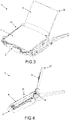
- the combiner 3 In storage position S the combiner 3 is folded down or folded in, respectively, into a recess or internal space of the protective housing as shown in Figures 1 and 2 . During operation of the vehicle the combiner 3 is folded out of the protective housing and set in its operating position O as shown in Figures 3 and 4 .
- the combiner 3 is a transparent panel that includes optical coatings that reflect those specific wavelengths that are projected by a HUD projector which is not explicitly shown in the Figures. Also a video data source like a computer that is usually required to project information via the projector on the combiner 3 and thus enable proper function of the HUD system 1 is not shown in the Figures.
- the HUD system 1 furthermore comprises a cover 4 to protect the combiner 3 in its storage position S to avoid scratches and dirt on the combiner 3.
- the drive mechanism 2 moves the cover 3 between a closed position C, symbolized by a cursor C, and an open position P, symbolized by a cursor P.
- the cover 4 in its closed position C protects the combiner 3 in its stored position S and the drive mechanism 2 first moves the cover 4 from its closed position C into its open position P and after that moves the combiner 3 from its stored position S into its operating position O to enable operation of the combiner 3.
- Figures 5 to 10 show this movement in three steps.
- the drive mechanism 2 comprises a main lever 5 and a support lever 6 to transform a rotational movement of a motor, which is not shown in the Figures, of the drive mechanism 2 into a linear movement to move the cover 4 in a guiding direction G between its open position P and its closed position C.
- the main lever 5 comprises a cover end 7 to pivotable connect with the cover 4 and a driver end 8 to pivotable connect with a rotational drive mechanism 9 of the drive mechanism 2 as shown in Figure 6 .
- the support lever 6 comprises a moving end 10 to pivotable connect to the main lever 5 and a fixed end 11 to pivotable connect to the housing of the HUD system 1.
- the rotational drive mechanism 9 comprises the motor that drives a motor driven gearwheel 12 meshing with a lever gearwheel 13 which is pivoted with the driver end 8 of the main lever 5.
- the HUD system 1 is realized with specific length and distance relations as shown in Figure 11 to enable the transformation of the rotational movement into the linear movement in the guiding direction G.
- the distance from the center of the lever gearwheel 13 to the fixed end 11 of the support lever 6 is 2 times L and the distance from the driver end 8 of the main lever 5 to the moving end 10 of the support lever is 2,5 times L and the distance from the moving end 10 of the support lever 6 to the cover end 7 of the mail lever is 2,5 times L and the length of the support lever 6 from its moving end 10 to its fixed end 11 is 2,5 times L.
- These length and distance relations ensure a substantially linear movement of the cover end 7 of the main lever 5 and the cover 4 in the guiding direction G what enables a smooth transition of the cover 4 between its closed position C and its open position P.
- the length of L may be varied dependent on the size of the HUD system 1.
- the combiner 3 of the HUD system 1 is pivoted between its operating position O and its storage position S around a combiner axis 14.
- the final angle of the combiner 3 in its operating position O may be adjustable by the user of the automobile to adjust it to the size of the user.
- the main lever 5 and the support lever 6 of the drive mechanism 2 are essentially in a parallel plane to the cover 4 in its open position P and its closed position C. This enables to reduce the volume of the housing of the HUD system 1 and eases to design the HUD system 1 into a dashboard of an automobile or airplane.
- the cover 4 is slideable along a curved guiding member 15 in the guiding direction G between the open position P and the closed position C of the cover 4. This has the advantage that the cover 4 is guided in a robust and secure way.
- the curved guiding member 15 is built to lower the position of the cover 4 at the beginning of the movement from the closed position C to the open position P in a direction T, as shown in Figure 7 , and after that to move the cover in an essential linear movement. This enables a uniform surface of the dashboard with the cover 4 in its closed position C and an overall flat housing of the HUD system 1.
- a further substantial advantage of the construction of the HUD system 1 is that the cover 4 is only connected with the cover end 7 of the main lever 5 to the drive mechanism 2. This reduces the number of parts and cost of the HUD system 1.
- FIG. 12 is a bottom view of the HUD system 1 of Figure 1 with the cover 4 in its closed position C and shows a detailed view of the cardan joint 16.
- the cardan joint 16 enables that the cover end 7 of the main lever 5 is slidable in a slide direction D essentially vertical to the guiding direction G in relation to the cover 4. This ensures to avoid side forces causing friction between the curved guiding member 15 and the cover 4 and enables a smooth movement of the cover 4 without situations of jam.
- the motor driven gearwheel 12 of the HUD system 1 comprises a further curved guiding member 17 on its end face to guide a driver pin 18 along a curve as shown in Figures 11 and 15 and 16 .
- the driver pin 18 engages via a combiner lever 19 with the combiner 4 to move the combiner 4 around the combiner axis 14 between its operating position O and its storage position S.
- the further curved guiding member 17 comprises a degressive curve in an area 20 to enable self-locking of the combiner 4 in its operating position O.
- This design has the advantage that the combiner 4 is very robust fixed in its operating position O to avoid vibrations of the combiner 4 and distortions of the information projected on the combiner 4.
- the motor driven gearwheel 12 and the lever gearwheel 13 comprise an area 21 of their perimeter without meshing to disconnect the motor driven gearwheel 12 from the lever gearwheel 13 as shown in Figures 16 and 17 .
- This enables the drive mechanism 2 to move the combiner 3 between its operating position O and its storage position S without moving the cover 4. This mechanism will be explained based on Figures 13 to 17 .
- Figure 13 is a top view of the HUD system 1 with removed cover 4 close to its open position O with meshed motor driven gearwheel 12 and the lever gearwheel 13.
- the motor turns the motor driven gearwheel 12 in the first rotary direction FR to completely open the cover 4 and move the combiner 3 from its storage position S into its operating position O.
- the motor driven gearwheel 12 is meshed in an area 22 with lever gearwheel 13 and turns lever gearwheel 13 in its first rotary direction FR.
- the cover end 7 of the main lever 5 reached its end position and the cover 4 its open position P while the area 21 of the perimeter of the motor driven gearwheel 12 and the lever gearwheel 13 without meshing is close to the area 22 where the motor driven gearwheel 12 and the lever gearwheel 13 still mesh.
- FIG 15 is a detailed view of the motor driven gearwheel 12 and the lever gearwheel 13 of the HUD system 1 of Figure 14 that shows the further curved guiding member 17 of the motor driven gearwheel 12. While the motor driven gearwheel 12 turns in its first rotary directioin FR the driver pin 18 fixed to the combiner lever 19 is guided along further curved guiding member 17 what results in a linear movement of the combiner lever 19 in its opening direction OD.
- Figure 16 is a top view of the HUD system 1 with removed cover 4 in its open position O while the motor driven gearwheel 12 and the lever gearwheel 13 are not meshed.
- the motor turned the motor driven gearwheel 12 further in its first rotary direction FR until the driver pin 18 reached the end of the further curved guiding member 17 and the combiner lever 19 pushed the combiner 3 into its operating position O as shown in Figures 4 and 17 .
- This has the advantage that the driver mechanism 2 only needs a single motor to drive the cover 4 and the combiner 3 into their different positions.
- the lever gearwheel 13 comprises one compared to the other teeth of the lever gearwheel 13 large tooth 23 as a first tooth at the end of the area 21 without teeth to enable smooth interconnection of the teeth of the lever gearwheel 13 with the teeth of the motor driven gearwheel 12 when connected again. This avoids a blocking situation of the gearwheels when connected again.
- the motor driven gearwheel 12 would comprise such a larger tooth to smoothen the interconnection of the teeth of the gearwheels.
Landscapes
- Physics & Mathematics (AREA)
- General Physics & Mathematics (AREA)
- Optics & Photonics (AREA)
- Instrument Panels (AREA)
- Devices For Indicating Variable Information By Combining Individual Elements (AREA)
Claims (10)
- Système d'affichage tête haute (1) comprenant un boîtier, un combineur (3) pour afficher des informations dans une position de fonctionnement (O) et un couvercle (4) pour protéger le combineur (3), dans lequel le combineur (3) est mobile entre la position de fonctionnement (O) et une position de stockage (S) et dans lequel le couvercle (4) est mobile entre une position ouverte (P) et une position fermée (C) pour protéger le combineur (3) dans sa position de stockage (S) avec le couvercle (4) dans sa position fermée, dans lequel le système d'affichage tête haute (1) comprend un mécanisme d'entraînement (2) pour déplacer le couvercle (4) entre sa position ouverte (P) et sa position fermée (C), lequel mécanisme d'entraînement (2) comprend un levier principal (5) et un levier de support (6) qui est pivoté avec une extrémité mobile (10) par rapport au levier principal (5) et avec une extrémité fixe (11) par rapport au boîtier, dans lequel le levier principal (5) est pivoté avec une extrémité de couvercle (7) par rapport au couvercle (4) et avec une extrémité d'entraînement (8) par rapport à un mécanisme d'entraînement en rotation (9) pour entraîner un déplacement sensiblement linéaire de l'extrémité de couvercle (7) du levier principal (5) lors du déplacement du couvercle (4) entre sa position ouverte (P) et sa position fermée (C), caractérisé en ce que
le couvercle (4) est uniquement relié à l'extrémité de couvercle (7) du levier principal (5) au mécanisme d'entraînement (2), le levier principal (5) et le levier de support (6) du mécanisme d'entraînement (2) étant sensiblement dans un plan parallèle au couvercle (4) dans sa position ouverte (P) et dans sa position fermée (C). - Système d'affichage tête haute (1) selon la revendication 1, caractérisé en ce que ladite liaison de l'extrémité de couvercle (7) du levier principal (5) du mécanisme d'entraînement (2) avec le couvercle (4) est formée par un joint à cardan (16).
- Système d'affichage tête haute (1) selon l'une quelconque des revendications précédentes, caractérisé en ce que le couvercle (4) peut coulisser le long d'un élément de guidage incurvé (15) dans une direction de guidage (G) entre la position ouverte (P) et la position fermée (C) du couvercle (4).
- Système d'affichage tête haute (1) selon la revendication 3, caractérisé en ce que la liaison unique pour relier le levier principal (5) au couvercle (4) peut coulisser sensiblement dans une direction (D) perpendiculaire à la direction de guidage (G).
- Système d'affichage tête haute (1) selon la revendication 3 ou la revendication 4, caractérisé en ce que l'élément de guidage incurvé (15) est construit pour abaisser la position du couvercle (4) au début du déplacement de la position fermée (C) à la position ouverte (P) et ensuite pour déplacer le couvercle (4) dans un déplacement sensiblement linéaire.
- Système d'affichage tête haute (1) selon les revendications 4 à 5, caractérisé en ce que la liaison unique pour relier le levier principal (5) au couvercle (4) peut coulisser dans une direction (T) sensiblement perpendiculaire à la direction (D) et à la direction de guidage (G).
- Système d'affichage tête haute (1) selon l'une quelconque des revendications précédentes, caractérisé en ce qu'un mécanisme d'entraînement en rotation (9) comprend un moteur qui entraîne une roue d'engrenage entraînée par moteur (12) engrenant avec une roue d'engrenage de levier (13) qui est pivotée avec l'extrémité d'entraînement (8) du levier principal (5).
- Système d'affichage tête haute (1) selon la revendication 7, caractérisé en ce que la roue d'engrenage entraînée par moteur (12) et la roue d'engrenage de levier (13) comprennent une zone (21) de leur périmètre sans engrènement pour déconnecter la roue d'engrenage entraînée par moteur (12) de la roue d'engrenage de levier (13) de manière à permettre au mécanisme d'entraînement (2) de déplacer le combineur (3) entre sa position de fonctionnement (O) et sa position de stockage (S) sans déplacer le couvercle (4).
- Système d'affichage tête haute (1) selon la revendication 8, caractérisé en ce que la roue d'engrenage entraînée par moteur (12) comprend un élément de guidage incurvé supplémentaire (17) sur sa face d'extrémité pour guider une broche d'entraînement (18) le long d'une courbe, laquelle broche d'entraînement (18) vient en prise avec le combineur (3) pour déplacer le combineur (3) entre sa position de fonctionnement (O) et sa position de stockage (S).
- Système d'affichage tête haute (1) selon la revendication 9, caractérisé en ce que l'élément de guidage incurvé supplémentaire (17) comprend une courbe dégressive de manière à permettre un auto-verrouillage du combineur (3) dans la position de fonctionnement (O).
Priority Applications (3)
| Application Number | Priority Date | Filing Date | Title |
|---|---|---|---|
| EP14171942.7A EP2955562B1 (fr) | 2014-06-11 | 2014-06-11 | Système d'affichage tête haute comportant un mécanisme d'entraînement pour déplacer un couvercle afin de protéger un combineur |
| CN201510309545.5A CN105301772B (zh) | 2014-06-11 | 2015-06-08 | 具有移动盖体以保护合成器的驱动机构的平视显示系统 |
| US14/736,024 US9864196B2 (en) | 2014-06-11 | 2015-06-10 | Head-up display system with a drive mechanism to move a cover to protect a combiner |
Applications Claiming Priority (1)
| Application Number | Priority Date | Filing Date | Title |
|---|---|---|---|
| EP14171942.7A EP2955562B1 (fr) | 2014-06-11 | 2014-06-11 | Système d'affichage tête haute comportant un mécanisme d'entraînement pour déplacer un couvercle afin de protéger un combineur |
Publications (2)
| Publication Number | Publication Date |
|---|---|
| EP2955562A1 EP2955562A1 (fr) | 2015-12-16 |
| EP2955562B1 true EP2955562B1 (fr) | 2023-01-04 |
Family
ID=50943122
Family Applications (1)
| Application Number | Title | Priority Date | Filing Date |
|---|---|---|---|
| EP14171942.7A Active EP2955562B1 (fr) | 2014-06-11 | 2014-06-11 | Système d'affichage tête haute comportant un mécanisme d'entraînement pour déplacer un couvercle afin de protéger un combineur |
Country Status (3)
| Country | Link |
|---|---|
| US (1) | US9864196B2 (fr) |
| EP (1) | EP2955562B1 (fr) |
| CN (1) | CN105301772B (fr) |
Families Citing this family (5)
| Publication number | Priority date | Publication date | Assignee | Title |
|---|---|---|---|---|
| EP3272569A1 (fr) * | 2015-03-19 | 2018-01-24 | Pioneer Corporation | Dispositif d'affichage |
| JP2016210266A (ja) * | 2015-05-07 | 2016-12-15 | パナソニックIpマネジメント株式会社 | パネル開閉装置 |
| CN106526847B (zh) * | 2015-09-10 | 2019-03-29 | 光宝科技股份有限公司 | 抬头显示装置 |
| JP6542689B2 (ja) * | 2016-02-04 | 2019-07-10 | ヒュンダイ・モービス・カンパニー・リミテッド | ヘッドアップディスプレイ装置 |
| KR102038356B1 (ko) * | 2016-02-18 | 2019-10-31 | 가부시키가이샤 덴소 | 헤드업 디스플레이 장치 |
Family Cites Families (13)
| Publication number | Priority date | Publication date | Assignee | Title |
|---|---|---|---|---|
| DE430716C (de) | 1923-10-27 | 1926-06-22 | Nasmith S Patents Ltd | Selbsttaetig regelnde Schaltvorrichtung fuer den Stapeltisch von selbsttaetigen Bogenfuehrern, insbesondere fuer Ritz- und Schneidmaschinen fuer die Pappschachtelherstellung |
| DE102006025382B3 (de) | 2006-05-31 | 2007-12-20 | Siemens Ag | Verschlussblendenvorrichtung |
| KR101433407B1 (ko) * | 2006-11-20 | 2014-08-26 | 존슨 컨트롤스 테크놀러지 컴퍼니 | 차량 장착용 디스플레이 유닛, 차량용 가상 화상 시스템 및 가상 디스플레이 장치의 사용 방법 |
| DE202007019170U1 (de) | 2007-03-29 | 2010-11-04 | Carl Zeiss Ag | HMD-Vorrichtung |
| DE102008023469A1 (de) * | 2008-05-14 | 2009-12-03 | Continental Automotive Gmbh | Anzeigeeinrichtung |
| EP2322972A1 (fr) | 2009-11-12 | 2011-05-18 | Johnson Controls Technology Company | Dispositif d'affichage, notamment pour véhicule automobile |
| US8427751B2 (en) | 2011-01-12 | 2013-04-23 | Lite-On It Corporation | Combiner positioning system for head-up display |
| JP5923251B2 (ja) * | 2011-06-08 | 2016-05-24 | 日本精機株式会社 | ヘッドアップディスプレイ装置 |
| EP2541303B1 (fr) | 2011-07-01 | 2017-12-20 | Johnson Controls Automotive Electronics GmbH | Affichage tête haute pour véhicule |
| JP5878712B2 (ja) * | 2011-09-06 | 2016-03-08 | 矢崎総業株式会社 | 車両用表示装置 |
| WO2013059662A1 (fr) | 2011-10-21 | 2013-04-25 | Jabil Circuit, Inc. | Système de positionnement de combinateur |
| JP5464219B2 (ja) * | 2012-02-03 | 2014-04-09 | 株式会社デンソー | 車両用ヘッドアップディスプレイ装置 |
| JP6080704B2 (ja) * | 2013-06-18 | 2017-02-15 | ミネベアミツミ株式会社 | 表示装置 |
-
2014
- 2014-06-11 EP EP14171942.7A patent/EP2955562B1/fr active Active
-
2015
- 2015-06-08 CN CN201510309545.5A patent/CN105301772B/zh active Active
- 2015-06-10 US US14/736,024 patent/US9864196B2/en active Active
Also Published As
| Publication number | Publication date |
|---|---|
| US9864196B2 (en) | 2018-01-09 |
| EP2955562A1 (fr) | 2015-12-16 |
| US20150362732A1 (en) | 2015-12-17 |
| CN105301772B (zh) | 2018-11-23 |
| CN105301772A (zh) | 2016-02-03 |
Similar Documents
| Publication | Publication Date | Title |
|---|---|---|
| EP2955563B1 (fr) | Système d'affichage tête haute comportant un mécanisme d'entraînement pour déplacer un combineur | |
| US9063327B2 (en) | Adjustable head-up display device | |
| US9864196B2 (en) | Head-up display system with a drive mechanism to move a cover to protect a combiner | |
| CN103797401B (zh) | 适于车辆的平视显示器 | |
| US7659868B2 (en) | Head-up display apparatus and cover-mirror unit used for the same | |
| US8427751B2 (en) | Combiner positioning system for head-up display | |
| EP1990675B1 (fr) | Dispositif d'affichage tête haute pour véhicules | |
| KR20150028561A (ko) | 차량용 헤드업 디스플레이 장치 | |
| JP2013054311A (ja) | 車両用表示装置 | |
| US10816797B2 (en) | Head-up display for a motor vehicle | |
| CN107390363B (zh) | 平视显示器系统 | |
| US9919600B2 (en) | Vehicle information display systems | |
| EP3064391A1 (fr) | Système d'affichage tête haute comportant des moyens d'entraînement en rotation disposés parallèlement à un multiplexeur pour déplacer le multiplexeur | |
| US9817234B2 (en) | Misuse detection for display combiner | |
| JP2018505435A (ja) | 調節可能な観察ウィンドウを有するヘッドアップディスプレイ | |
| EP2479598B1 (fr) | Système de positionnement pour affichage tête haute | |
| US20180037115A1 (en) | Display device | |
| CN107462990A (zh) | 抬头显示器 | |
| CN102141681B (zh) | 显示装置 | |
| WO2015111476A1 (fr) | Dispositif d'affichage tête haute | |
| JP2006248322A (ja) | 車両用表示装置 |
Legal Events
| Date | Code | Title | Description |
|---|---|---|---|
| PUAI | Public reference made under article 153(3) epc to a published international application that has entered the european phase |
Free format text: ORIGINAL CODE: 0009012 |
|
| AK | Designated contracting states |
Kind code of ref document: A1 Designated state(s): AL AT BE BG CH CY CZ DE DK EE ES FI FR GB GR HR HU IE IS IT LI LT LU LV MC MK MT NL NO PL PT RO RS SE SI SK SM TR |
|
| AX | Request for extension of the european patent |
Extension state: BA ME |
|
| 17P | Request for examination filed |
Effective date: 20160613 |
|
| RBV | Designated contracting states (corrected) |
Designated state(s): AL AT BE BG CH CY CZ DE DK EE ES FI FR GB GR HR HU IE IS IT LI LT LU LV MC MK MT NL NO PL PT RO RS SE SI SK SM TR |
|
| STAA | Information on the status of an ep patent application or granted ep patent |
Free format text: STATUS: EXAMINATION IS IN PROGRESS |
|
| 17Q | First examination report despatched |
Effective date: 20200103 |
|
| GRAP | Despatch of communication of intention to grant a patent |
Free format text: ORIGINAL CODE: EPIDOSNIGR1 |
|
| STAA | Information on the status of an ep patent application or granted ep patent |
Free format text: STATUS: GRANT OF PATENT IS INTENDED |
|
| INTG | Intention to grant announced |
Effective date: 20220819 |
|
| GRAS | Grant fee paid |
Free format text: ORIGINAL CODE: EPIDOSNIGR3 |
|
| GRAA | (expected) grant |
Free format text: ORIGINAL CODE: 0009210 |
|
| STAA | Information on the status of an ep patent application or granted ep patent |
Free format text: STATUS: THE PATENT HAS BEEN GRANTED |
|
| AK | Designated contracting states |
Kind code of ref document: B1 Designated state(s): AL AT BE BG CH CY CZ DE DK EE ES FI FR GB GR HR HU IE IS IT LI LT LU LV MC MK MT NL NO PL PT RO RS SE SI SK SM TR |
|
| REG | Reference to a national code |
Ref country code: GB Ref legal event code: FG4D |
|
| REG | Reference to a national code |
Ref country code: DE Ref legal event code: R096 Ref document number: 602014085976 Country of ref document: DE |
|
| REG | Reference to a national code |
Ref country code: CH Ref legal event code: EP |
|
| REG | Reference to a national code |
Ref country code: AT Ref legal event code: REF Ref document number: 1542370 Country of ref document: AT Kind code of ref document: T Effective date: 20230115 |
|
| REG | Reference to a national code |
Ref country code: IE Ref legal event code: FG4D |
|
| REG | Reference to a national code |
Ref country code: LT Ref legal event code: MG9D |
|
| REG | Reference to a national code |
Ref country code: NL Ref legal event code: MP Effective date: 20230104 |
|
| REG | Reference to a national code |
Ref country code: AT Ref legal event code: MK05 Ref document number: 1542370 Country of ref document: AT Kind code of ref document: T Effective date: 20230104 |
|
| PG25 | Lapsed in a contracting state [announced via postgrant information from national office to epo] |
Ref country code: NL Free format text: LAPSE BECAUSE OF FAILURE TO SUBMIT A TRANSLATION OF THE DESCRIPTION OR TO PAY THE FEE WITHIN THE PRESCRIBED TIME-LIMIT Effective date: 20230104 |
|
| PG25 | Lapsed in a contracting state [announced via postgrant information from national office to epo] |
Ref country code: RS Free format text: LAPSE BECAUSE OF FAILURE TO SUBMIT A TRANSLATION OF THE DESCRIPTION OR TO PAY THE FEE WITHIN THE PRESCRIBED TIME-LIMIT Effective date: 20230104 Ref country code: PT Free format text: LAPSE BECAUSE OF FAILURE TO SUBMIT A TRANSLATION OF THE DESCRIPTION OR TO PAY THE FEE WITHIN THE PRESCRIBED TIME-LIMIT Effective date: 20230504 Ref country code: NO Free format text: LAPSE BECAUSE OF FAILURE TO SUBMIT A TRANSLATION OF THE DESCRIPTION OR TO PAY THE FEE WITHIN THE PRESCRIBED TIME-LIMIT Effective date: 20230404 Ref country code: LV Free format text: LAPSE BECAUSE OF FAILURE TO SUBMIT A TRANSLATION OF THE DESCRIPTION OR TO PAY THE FEE WITHIN THE PRESCRIBED TIME-LIMIT Effective date: 20230104 Ref country code: LT Free format text: LAPSE BECAUSE OF FAILURE TO SUBMIT A TRANSLATION OF THE DESCRIPTION OR TO PAY THE FEE WITHIN THE PRESCRIBED TIME-LIMIT Effective date: 20230104 Ref country code: HR Free format text: LAPSE BECAUSE OF FAILURE TO SUBMIT A TRANSLATION OF THE DESCRIPTION OR TO PAY THE FEE WITHIN THE PRESCRIBED TIME-LIMIT Effective date: 20230104 Ref country code: ES Free format text: LAPSE BECAUSE OF FAILURE TO SUBMIT A TRANSLATION OF THE DESCRIPTION OR TO PAY THE FEE WITHIN THE PRESCRIBED TIME-LIMIT Effective date: 20230104 Ref country code: AT Free format text: LAPSE BECAUSE OF FAILURE TO SUBMIT A TRANSLATION OF THE DESCRIPTION OR TO PAY THE FEE WITHIN THE PRESCRIBED TIME-LIMIT Effective date: 20230104 |
|
| PG25 | Lapsed in a contracting state [announced via postgrant information from national office to epo] |
Ref country code: SE Free format text: LAPSE BECAUSE OF FAILURE TO SUBMIT A TRANSLATION OF THE DESCRIPTION OR TO PAY THE FEE WITHIN THE PRESCRIBED TIME-LIMIT Effective date: 20230104 Ref country code: PL Free format text: LAPSE BECAUSE OF FAILURE TO SUBMIT A TRANSLATION OF THE DESCRIPTION OR TO PAY THE FEE WITHIN THE PRESCRIBED TIME-LIMIT Effective date: 20230104 Ref country code: IS Free format text: LAPSE BECAUSE OF FAILURE TO SUBMIT A TRANSLATION OF THE DESCRIPTION OR TO PAY THE FEE WITHIN THE PRESCRIBED TIME-LIMIT Effective date: 20230504 Ref country code: GR Free format text: LAPSE BECAUSE OF FAILURE TO SUBMIT A TRANSLATION OF THE DESCRIPTION OR TO PAY THE FEE WITHIN THE PRESCRIBED TIME-LIMIT Effective date: 20230405 Ref country code: FI Free format text: LAPSE BECAUSE OF FAILURE TO SUBMIT A TRANSLATION OF THE DESCRIPTION OR TO PAY THE FEE WITHIN THE PRESCRIBED TIME-LIMIT Effective date: 20230104 |
|
| REG | Reference to a national code |
Ref country code: DE Ref legal event code: R097 Ref document number: 602014085976 Country of ref document: DE |
|
| PG25 | Lapsed in a contracting state [announced via postgrant information from national office to epo] |
Ref country code: SM Free format text: LAPSE BECAUSE OF FAILURE TO SUBMIT A TRANSLATION OF THE DESCRIPTION OR TO PAY THE FEE WITHIN THE PRESCRIBED TIME-LIMIT Effective date: 20230104 Ref country code: RO Free format text: LAPSE BECAUSE OF FAILURE TO SUBMIT A TRANSLATION OF THE DESCRIPTION OR TO PAY THE FEE WITHIN THE PRESCRIBED TIME-LIMIT Effective date: 20230104 Ref country code: EE Free format text: LAPSE BECAUSE OF FAILURE TO SUBMIT A TRANSLATION OF THE DESCRIPTION OR TO PAY THE FEE WITHIN THE PRESCRIBED TIME-LIMIT Effective date: 20230104 Ref country code: DK Free format text: LAPSE BECAUSE OF FAILURE TO SUBMIT A TRANSLATION OF THE DESCRIPTION OR TO PAY THE FEE WITHIN THE PRESCRIBED TIME-LIMIT Effective date: 20230104 Ref country code: CZ Free format text: LAPSE BECAUSE OF FAILURE TO SUBMIT A TRANSLATION OF THE DESCRIPTION OR TO PAY THE FEE WITHIN THE PRESCRIBED TIME-LIMIT Effective date: 20230104 |
|
| PLBE | No opposition filed within time limit |
Free format text: ORIGINAL CODE: 0009261 |
|
| STAA | Information on the status of an ep patent application or granted ep patent |
Free format text: STATUS: NO OPPOSITION FILED WITHIN TIME LIMIT |
|
| PG25 | Lapsed in a contracting state [announced via postgrant information from national office to epo] |
Ref country code: SK Free format text: LAPSE BECAUSE OF FAILURE TO SUBMIT A TRANSLATION OF THE DESCRIPTION OR TO PAY THE FEE WITHIN THE PRESCRIBED TIME-LIMIT Effective date: 20230104 |
|
| 26N | No opposition filed |
Effective date: 20231005 |
|
| PG25 | Lapsed in a contracting state [announced via postgrant information from national office to epo] |
Ref country code: MC Free format text: LAPSE BECAUSE OF FAILURE TO SUBMIT A TRANSLATION OF THE DESCRIPTION OR TO PAY THE FEE WITHIN THE PRESCRIBED TIME-LIMIT Effective date: 20230104 |
|
| PG25 | Lapsed in a contracting state [announced via postgrant information from national office to epo] |
Ref country code: SI Free format text: LAPSE BECAUSE OF FAILURE TO SUBMIT A TRANSLATION OF THE DESCRIPTION OR TO PAY THE FEE WITHIN THE PRESCRIBED TIME-LIMIT Effective date: 20230104 Ref country code: MC Free format text: LAPSE BECAUSE OF FAILURE TO SUBMIT A TRANSLATION OF THE DESCRIPTION OR TO PAY THE FEE WITHIN THE PRESCRIBED TIME-LIMIT Effective date: 20230104 |
|
| REG | Reference to a national code |
Ref country code: CH Ref legal event code: PL |
|
| REG | Reference to a national code |
Ref country code: BE Ref legal event code: MM Effective date: 20230630 |
|
| GBPC | Gb: european patent ceased through non-payment of renewal fee |
Effective date: 20230611 |
|
| PG25 | Lapsed in a contracting state [announced via postgrant information from national office to epo] |
Ref country code: LU Free format text: LAPSE BECAUSE OF NON-PAYMENT OF DUE FEES Effective date: 20230611 |
|
| REG | Reference to a national code |
Ref country code: IE Ref legal event code: MM4A |
|
| PG25 | Lapsed in a contracting state [announced via postgrant information from national office to epo] |
Ref country code: LU Free format text: LAPSE BECAUSE OF NON-PAYMENT OF DUE FEES Effective date: 20230611 |
|
| PG25 | Lapsed in a contracting state [announced via postgrant information from national office to epo] |
Ref country code: IE Free format text: LAPSE BECAUSE OF NON-PAYMENT OF DUE FEES Effective date: 20230611 |
|
| PG25 | Lapsed in a contracting state [announced via postgrant information from national office to epo] |
Ref country code: IE Free format text: LAPSE BECAUSE OF NON-PAYMENT OF DUE FEES Effective date: 20230611 Ref country code: CH Free format text: LAPSE BECAUSE OF NON-PAYMENT OF DUE FEES Effective date: 20230630 Ref country code: GB Free format text: LAPSE BECAUSE OF NON-PAYMENT OF DUE FEES Effective date: 20230611 |
|
| PG25 | Lapsed in a contracting state [announced via postgrant information from national office to epo] |
Ref country code: IT Free format text: LAPSE BECAUSE OF FAILURE TO SUBMIT A TRANSLATION OF THE DESCRIPTION OR TO PAY THE FEE WITHIN THE PRESCRIBED TIME-LIMIT Effective date: 20230104 Ref country code: BE Free format text: LAPSE BECAUSE OF NON-PAYMENT OF DUE FEES Effective date: 20230630 |
|
| PG25 | Lapsed in a contracting state [announced via postgrant information from national office to epo] |
Ref country code: BG Free format text: LAPSE BECAUSE OF FAILURE TO SUBMIT A TRANSLATION OF THE DESCRIPTION OR TO PAY THE FEE WITHIN THE PRESCRIBED TIME-LIMIT Effective date: 20230104 |
|
| PG25 | Lapsed in a contracting state [announced via postgrant information from national office to epo] |
Ref country code: BG Free format text: LAPSE BECAUSE OF FAILURE TO SUBMIT A TRANSLATION OF THE DESCRIPTION OR TO PAY THE FEE WITHIN THE PRESCRIBED TIME-LIMIT Effective date: 20230104 |
|
| PGFP | Annual fee paid to national office [announced via postgrant information from national office to epo] |
Ref country code: DE Payment date: 20250618 Year of fee payment: 12 |
|
| PGFP | Annual fee paid to national office [announced via postgrant information from national office to epo] |
Ref country code: FR Payment date: 20250626 Year of fee payment: 12 |
|
| PG25 | Lapsed in a contracting state [announced via postgrant information from national office to epo] |
Ref country code: CY Free format text: LAPSE BECAUSE OF FAILURE TO SUBMIT A TRANSLATION OF THE DESCRIPTION OR TO PAY THE FEE WITHIN THE PRESCRIBED TIME-LIMIT; INVALID AB INITIO Effective date: 20140611 |
|
| PG25 | Lapsed in a contracting state [announced via postgrant information from national office to epo] |
Ref country code: HU Free format text: LAPSE BECAUSE OF FAILURE TO SUBMIT A TRANSLATION OF THE DESCRIPTION OR TO PAY THE FEE WITHIN THE PRESCRIBED TIME-LIMIT; INVALID AB INITIO Effective date: 20140611 |
|
| PG25 | Lapsed in a contracting state [announced via postgrant information from national office to epo] |
Ref country code: TR Free format text: LAPSE BECAUSE OF FAILURE TO SUBMIT A TRANSLATION OF THE DESCRIPTION OR TO PAY THE FEE WITHIN THE PRESCRIBED TIME-LIMIT Effective date: 20230104 |