EP2955594A2 - Terminal mobile de type montre et procédé de commande pour le terminal mobile - Google Patents
Terminal mobile de type montre et procédé de commande pour le terminal mobile Download PDFInfo
- Publication number
- EP2955594A2 EP2955594A2 EP15161063.1A EP15161063A EP2955594A2 EP 2955594 A2 EP2955594 A2 EP 2955594A2 EP 15161063 A EP15161063 A EP 15161063A EP 2955594 A2 EP2955594 A2 EP 2955594A2
- Authority
- EP
- European Patent Office
- Prior art keywords
- mobile terminal
- band
- unit
- band unit
- user input
- Prior art date
- Legal status (The legal status is an assumption and is not a legal conclusion. Google has not performed a legal analysis and makes no representation as to the accuracy of the status listed.)
- Granted
Links
Images







Classifications
-
- G—PHYSICS
- G04—HOROLOGY
- G04G—ELECTRONIC TIME-PIECES
- G04G21/00—Input or output devices integrated in time-pieces
- G04G21/08—Touch switches specially adapted for time-pieces
-
- G—PHYSICS
- G04—HOROLOGY
- G04G—ELECTRONIC TIME-PIECES
- G04G21/00—Input or output devices integrated in time-pieces
- G04G21/02—Detectors of external physical values, e.g. temperature
- G04G21/025—Detectors of external physical values, e.g. temperature for measuring physiological data
-
- G—PHYSICS
- G04—HOROLOGY
- G04G—ELECTRONIC TIME-PIECES
- G04G21/00—Input or output devices integrated in time-pieces
- G04G21/02—Detectors of external physical values, e.g. temperature
-
- G—PHYSICS
- G04—HOROLOGY
- G04G—ELECTRONIC TIME-PIECES
- G04G21/00—Input or output devices integrated in time-pieces
- G04G21/04—Input or output devices integrated in time-pieces using radio waves
-
- G—PHYSICS
- G04—HOROLOGY
- G04G—ELECTRONIC TIME-PIECES
- G04G9/00—Visual time or date indication means
- G04G9/0064—Visual time or date indication means in which functions not related to time can be displayed
-
- G—PHYSICS
- G06—COMPUTING OR CALCULATING; COUNTING
- G06F—ELECTRIC DIGITAL DATA PROCESSING
- G06F1/00—Details not covered by groups G06F3/00 - G06F13/00 and G06F21/00
- G06F1/16—Constructional details or arrangements
- G06F1/1613—Constructional details or arrangements for portable computers
- G06F1/163—Wearable computers, e.g. on a belt
Definitions
- the present invention relates to a watch type mobile terminal wearable on a wrist.
- a terminal may be classified into a mobile (portable) terminal and a stationary terminal according to a moveable state.
- the mobile terminal may be also classified into a handheld terminal and a vehicle mount terminal according to a user's carrying method.
- the terminal can support more complicated functions such as capturing images or video, reproducing music or video files, playing games and receiving broadcast signals.
- the mobile terminal may be embodied in the form of a multimedia player or a device.
- Various attempts have been made to implement complicated functions in such a multimedia device by using hardware or software. For instance, a user interface (UI), which allows a user to search for or select functions in an easy and convenient manner is provided.
- UI user interface
- the mobile terminal is regarded as a personal belonging for expressing the user's own personality
- various design shapes of the mobile terminal are required.
- the design shapes also include structural changes and improvements which enable the user to more conveniently use the mobile terminal.
- a watch type mobile terminal that can be used while being worn on a user's wrist may be considered as one of the structural changes and improvements.
- an aspect of the detailed description is to provide a watch type mobile terminal in which new user inputs and new outputs of the terminal are possible.
- Another aspect of the detailed description is to provide a watch type mobile terminal in which a plurality of input forms can be defined using a band unit.
- a watch type mobile terminal wearable on a wrist includes: a main body configured to have a display unit; a band unit connected to the main body so that the mobile terminal is worn on the wrist, the band unit surrounding the wrist; a sensing unit configured to sense a user input applied to the band unit; and a controller configured to process the user input applied to the band unit as a control command with respect to the mobile terminal.
- the band unit may have a plurality of areas for sensing the user input.
- the controller may process different commands based on an area to which the user input is applied among the plurality of areas.
- the band unit may include first and second bands respectively connected to both sides of the main body.
- the plurality of areas may include a first area formed in the first band, a second area formed in the second band, and a third area in which the first and second bands are overlapped with each other or connected to each other.
- the third area may be an area for connecting the first and second bands to be engaged with each other at end portions of the first and second bands.
- the band unit may be made to sense a touch input, and the user input may be a touch input applied to the band unit.
- the controller may process different control commands based on a kind of the touch input applied to the same area of the band unit.
- control related to the display unit may be performed by the control command. If the user is applied to the band unit in a state in which screen information is output on the display unit, at least one portion of the screen information may be changed. If the user input is applied to the band unit in a state in which an indicator for indicating an object to be selected is included in the screen information, the position of the indicator may be moved in response to the user input.
- control related to the event may be performed.
- the controller may output notification information for notifying that the event has occurred.
- the outputting of the notification information may be controlled corresponding to that the user input is applied in the state in which the notification information is output.
- the controller may output detailed information corresponding to the event through at least one of predetermined manners, corresponding to the user input.
- the controller may transmit predetermined information to another terminal related to the event, corresponding to the user input.
- the band unit may include a first band connected to one side of the main body, and a second band connected to the other side of the main body.
- a double band unit may be formed by overlapping or connection between the first and second band.
- the sensing unit may be made to sense a user input applied to the double band unit.
- the control commands may be differently set based on a position at which a touch input in the double band unit.
- the user input may include movement with respect to at least one portion of the part forming the double band unit in the first and second bands.
- the controller may execute a predetermined operation mode.
- the execution of the operation mode may be performed regardless of whether the display unit is activated.
- a function performed in the operation mode may be controlled using an additional user input applied to the band unit.
- the user input may be any one of a plurality of touch inputs applied to the band unit.
- Each of the plurality of touch inputs may be defined as an execution command with respect to any one of a plurality of operation modes.
- the band unit may include first and second bands respectively connected to both sides of the main body, the first and second bands being fastened to each other.
- the controller may process different control commands based on when the user input is applied in the state in which the first and second bands are fastened to each other and when the fastening is released.
- a function being performed in the state in which the first and second bands are fastened to each other may be stopped when the fastening is released. If the fastening is released, notification information for notifying that the performance of the function is impossible may be output.
- a terminal in the present description may include a mobile terminal such as a portable phone, a smart phone, a notebook computer, a digital broadcasting terminal, Personal Digital Assistants (PDA), Portable Multimedia Player (PMP), a navigation system, a slate PC, a tablet PC, an ultra book, a wearable device (e.g., smart watch), a glass-type terminal (e.g., smart glass), a head mounted display (HMD), etc.
- a mobile terminal such as a portable phone, a smart phone, a notebook computer, a digital broadcasting terminal, Personal Digital Assistants (PDA), Portable Multimedia Player (PMP), a navigation system, a slate PC, a tablet PC, an ultra book, a wearable device (e.g., smart watch), a glass-type terminal (e.g., smart glass), a head mounted display (HMD), etc.
- PDA Personal Digital Assistants
- PMP Portable Multimedia Player
- HMD head mounted display
- the present invention may be also applicable to a fixed terminal such as a digital TV, a desktop computer and a digital signage, except for specific configurations for mobility.
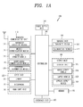
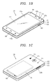
- FIGS. 1A-1C where FIG. 1A is a block diagram of a mobile terminal in accordance with the present invention, and FIGS. 1B and 1C are conceptual views of one example of the mobile terminal, viewed from different directions.
- the mobile terminal 100 is shown having components such as a wireless communication unit 110, an input unit 120, a sensing unit 140, an output unit 150, an interface unit 160, a memory 170, a controller 180, and a power supply unit 190. It is understood that implementing all of the illustrated components of FIG. 1A is not a requirement, and that greater or fewer components may alternatively be implemented.
- the mobile terminal 100 is shown having wireless communication unit 110 configured with several commonly implemented components.
- the wireless communication unit 110 typically includes one or more components which permit wireless communication between the mobile terminal 100 and a wireless communication system or network within which the mobile terminal is located.
- the wireless communication unit 110 typically includes one or more modules which permit communications such as wireless communications between the mobile terminal 100 and a wireless communication system, communications between the mobile terminal 100 and another mobile terminal, communications between the mobile terminal 100 and an external server. Further, the wireless communication unit 110 typically includes one or more modules which connect the mobile terminal 100 to one or more networks. To facilitate such communications, the wireless communication unit 110 includes one or more of a broadcast receiving module 111, a mobile communication module 112, a wireless Internet module 113, a short-range communication module 114, and a location information module 115.
- the input unit 120 includes a camera 121 for obtaining images or video, a microphone 122, which is one type of audio input device for inputting an audio signal, and a user input unit 123 (for example, a touch key, a push key, a mechanical key, a soft key, and the like) for allowing a user to input information.
- Data for example, audio, video, image, and the like
- controller 180 may analyze and process data (for example, audio, video, image, and the like) according to device parameters, user commands, and combinations thereof.
- the sensing unit 140 is typically implemented using one or more sensors configured to sense internal information of the mobile terminal, the surrounding environment of the mobile terminal, user information, and the like.
- the sensing unit 140 is shown having a proximity sensor 141 and an illumination sensor 142.
- the sensing unit 140 may alternatively or additionally include other types of sensors or devices, such as a touch sensor, an acceleration sensor, a magnetic sensor, a G-sensor, a gyroscope sensor, a motion sensor, an RGB sensor, an infrared (IR) sensor, a finger scan sensor, a ultrasonic sensor, an optical sensor (for example, camera 121), a microphone 122, a battery gauge, an environment sensor (for example, a barometer, a hygrometer, a thermometer, a radiation detection sensor, a thermal sensor, and a gas sensor, among others), and a chemical sensor (for example, an electronic nose, a health care sensor, a biometric sensor, and the like), to name a few.
- the mobile terminal 100 may be configured to utilize information obtained from sensing unit 140, and in particular, information obtained from one or more sensors of the sensing unit 140, and combinations thereof.
- the output unit 150 is typically configured to output various types of information, such as audio, video, tactile output, and the like.
- the output unit 150 is shown having a display unit 151, an audio output module 152, a haptic module 153, and an optical output module 154.
- the display unit 151 may have an inter-layered structure or an integrated structure with a touch sensor in order to facilitate a touch screen.
- the touch screen may provide an output interface between the mobile terminal 100 and a user, as well as function as the user input unit 123 which provides an input interface between the mobile terminal 100 and the user.
- the interface unit 160 serves as an interface with various types of external devices that can be coupled to the mobile terminal 100.
- the interface unit 160 may include any of wired or wireless ports, external power supply ports, wired or wireless data ports, memory card ports, ports for connecting a device having an identification module, audio input/output (I/O) ports, video I/O ports, earphone ports, and the like.
- the mobile terminal 100 may perform assorted control functions associated with a connected external device, in response to the external device being connected to the interface unit 160.
- the memory 170 is typically implemented to store data to support various functions or features of the mobile terminal 100.
- the memory 170 may be configured to store application programs executed in the mobile terminal 100, data or instructions for operations of the mobile terminal 100, and the like. Some of these application programs may be downloaded from an external server via wireless communication. Other application programs may be installed within the mobile terminal 100 at time of manufacturing or shipping, which is typically the case for basic functions of the mobile terminal 100 (for example, receiving a call, placing a call, receiving a message, sending a message, and the like). It is common for application programs to be stored in the memory 170, installed in the mobile terminal 100, and executed by the controller 180 to perform an operation (or function) for the mobile terminal 100.
- the controller 180 typically functions to control overall operation of the mobile terminal 100, in addition to the operations associated with the application programs.
- the controller 180 may provide or process information or functions appropriate for a user by processing signals, data, information and the like, which are input or output by the various components depicted in FIG. 1A , or activating application programs stored in the memory 170.
- the controller 180 controls some or all of the components illustrated in FIGS. 1A-1C according to the execution of an application program that have been stored in the memory 170.
- the power supply unit 190 can be configured to receive external power or provide internal power in order to supply appropriate power required for operating elements and components included in the mobile terminal 100.
- the power supply unit 190 may include a battery, and the battery may be configured to be embedded in the terminal body, or configured to be detachable from the terminal body.
- a mobile terminal may be configured as a device which is wearable on a human body. Such devices go beyond the usual technique of a user grasping the mobile terminal using their hand. Examples of the wearable device include a smart watch, a smart glass, a head mounted display (HMD), and the like.
- HMD head mounted display
- a typical wearable device can exchange data with (or cooperate with) another mobile terminal 100.
- the wearable device generally has functionality that is less than the cooperating mobile terminal.
- the short-range communication module 114 of a mobile terminal 100 may sense or recognize a wearable device that is near-enough to communicate with the mobile terminal.
- the controller 180 may transmit data processed in the mobile terminal 100 to the wearable device via the short-range communication module 114, for example.
- a user of the wearable device can use the data processed in the mobile terminal 100 on the wearable device. For example, when a call is received in the mobile terminal 100, the user can answer the call using the wearable device. Also, when a message is received in the mobile terminal 100, the user can check the received message using the wearable device.
- FIG. 2 is a perspective view illustrating one example of a watch-type mobile terminal 300 in accordance with another exemplary embodiment.
- the watch-type mobile terminal 300 includes a main body 301 with a display unit 351 and a band 302 connected to the main body 301 to be wearable on a wrist.
- mobile terminal 300 may be configured to include features that are the same or similar to that of mobile terminal 100 of FIGS. 1A-1C .
- the main body 301 may include a case having a certain appearance.
- the case may include a first case 301 a and a second case 301 b cooperatively defining an inner space for accommodating various electronic components.
- Other configurations are possible.
- a single case may alternatively be implemented, with such a case being configured to define the inner space, thereby implementing a mobile terminal 300 with a uni-body.
- the watch-type mobile terminal 300 can perform wireless communication, and an antenna for the wireless communication can be installed in the main body 301.
- the antenna may extend its function using the case.
- a case including a conductive material may be electrically connected to the antenna to extend a ground area or a radiation area.
- the display unit 351 is shown located at the front side of the main body 301 so that displayed information is viewable to a user.
- the display unit 351 includes a touch sensor so that the display unit can function as a touch screen.
- window 351 a is positioned on the first case 301 a to form a front surface of the terminal body together with the first case 301 a.
- the illustrated embodiment includes audio output module 352, a camera 321, a microphone 322, and a user input unit 323 positioned on the main body 301.
- audio output module 352 When the display unit 351 is implemented as a touch screen, additional function keys may be minimized or eliminated.
- the user input unit 323 may be omitted.
- the band 302 is commonly worn on the user's wrist and may be made of a flexible material for facilitating wearing of the device.
- the band 302 may be made of fur, rubber, silicon, synthetic resin, or the like.
- the band 302 may also be configured to be detachable from the main body 301. Accordingly, the band 302 may be replaceable with various types of bands according to a user's preference.
- the band 302 may be used for extending the performance of the antenna.
- the band may include therein a ground extending portion (not shown) electrically connected to the antenna to extend a ground area.
- the band 302 may include fastener 302a.
- the fastener 302a may be implemented into a buckle type, a snap-fit hook structure, a Velcro® type, or the like, and include a flexible section or material.
- the drawing illustrates an example that the fastener 302a is implemented using a buckle.
- the controller 180 may control functions of the terminal using a band of the mobile terminal.
- a method for defining a plurality of input forms and controlling operations of the display unit 351 using the input forms is provided as a control method.
- a method for controlling functions of the watch type mobile terminal using the band will be described in detail with reference to the accompanying drawings.
- the band will be divided into first and second bands connected to each other by a fastener 302a.
- the band 302 described with reference to FIG. 2 will be referred to as a band unit 302 as a meaning that is a portion including the first and second bands.
- the first band is described using reference numeral "303”
- the second band is described using reference numeral "304”.
- the first and second bands will be described as the "band unit 302" instead of the reference numerals for representing the first and second bands.
- FIG. 3 is a flowchart illustrating a control method according to an exemplary embodiment.
- FIG. 4 is a conceptual diagram illustrating a band area applied to the control method illustrated in FIG. 3 .
- the sensing unit 140 (see FIG. 1A ) of the watch type mobile terminal is activated (S310).
- the sensing unit 140 is configured to receive a user input applied to the band unit, and activation means that the sensing unit 140 is prepared in a ready state for receiving the user input.
- the sensing unit 140 includes one or more sensors for sensing a user input applied to the band unit, and the sensor may be disposed in the band unit.
- the sensor disposed in the band unit may be activated to always sense the user input. That is, the sensor located in the band unit may be in a continuously activated (always-on) state while the power is being supplied to the controller.
- other sensors except the sensor located in the band unit may be non-activated in the sleep mode. In this case, when a user input is sensed by the sensor disposed in the band unit, the other sensors may be activated.
- the sensor located in the band unit may be activated only when a user input applied to another portion exists in the state in which the sensor is non-activated.
- the sensor located in the band unit may be activated if the terminal senses touch inputs (e.g., first and second tappings) consecutively applied to the display unit 351 at a time interval.
- the sensor located in the band unit may be activated if a push input is applied to a separate physical key provided in the terminal.
- the sensing unit senses a user input applied to the band unit (S320).
- the user input may be an input using a predetermined method, which is linked with a function of inputting a control command to the terminal.
- the predetermined method may become a touch input or physical input (a push input, a bend input, a flip input, or the like).
- the sensor located in the band unit may be configured to sense at least the touch input or the physical input, which are applied to the band unit. More specifically, the sensor may be a touch sensor for sensing the touch input or a resonant sensor. Alternatively, the sensor may be a dome switch or piezoelectric sensor for sensing the push input, or may be a bending sensor or hole sensor for sensing the bend input, flip input, or the like.
- two or more of the touch sensor, the dome switch, the piezoelectric sensor, the bending sensor and the hole sensor may be combined together, so that the sensing unit senses all the touch input, the push input, the bend input, the flip input, and the like.
- the present invention is not necessarily limited thereto, and the touch input, the push input, the bend input and the flip input may be sensed by at least the proximity sensor 141, the illumination sensor 142, an acceleration sensor, a motion sensor, an RGB sensor, an infrared sensor (IR sensor), a finger scan sensor, an ultrasonic sensor or an optical sensor (e.g., the camera (see 121)).
- the band unit has a plurality of areas for sensing the user's input. At least one of the sensors described above may be provided in the plurality of areas.
- the controller may detect a control command applied to at least one of the plurality of areas, using information sensed in any one of the sensors, or may recognize a control command applied to at least one of the plurality of areas by combining information sensed in two or more sensors.
- the band unit 302 includes first and second bands 303 and 304 each connected to one of the sides of the main body, and the plurality of areas are defined by fastening between the first and second bands 303 and 304.
- the first band 303 is connected to one end (top end) of the main body, and the second band 304 is connected to the other end (bottom end) of the main body.
- the first and second bands 303 and 304 are fastened to each other by a fastener 302a (see FIG. 2 ) so that the terminal is worn on a wrist.
- the first and second bands 303 and 304 may be separated from each other.
- the present invention is not necessarily limited thereto. Functions described herein may be applied even when the first band is connected to the bottom end and the second band is connected to the top end.
- the plurality of areas include a first area 305a, a second area 305b and a third area 305c.
- the first area 305a may be formed in the first band 303
- the second area 305b may be formed in the second band 304.
- the third area 305c may be an area in which the first and second bands 303 and 304 are overlapped with each other. More specifically, the first area 305a may be an area except the third area 305 in the first band 303, and the second area 305b may be an area except the third area 305c in the second band 304.
- the band unit may be formed so that the length of the band unit can be adjusted when the terminal is worn on the wrist.
- the present invention is not necessarily limited thereto, and the third area may be defined as, for example, an area in which the first and second bands 303 and 304 are connected to each other.
- the third area may be an area for connecting the first and second bands 303 and 304 so that the first and second bands 303 and 304 are engaged with each other.
- a double band unit may be formed by the overlapping or connection of the first and second bands 303 and 304, and the sensing unit may be configured to sense a user input applied to the double band unit.
- the third area illustrates only the area in which the first and second bands 303 and 304 are overlapped with each other.
- the third area may be the area in which the first and second bands 303 and 304 are connected to each other (or the area for connecting the first and second bands 303 and 304 so that the first and second bands 303 and 304 are engaged with each other) or the double band unit
- the sizes of the first, second and third areas 305a, 305b and 305c may be changed by the adjustment of the length.
- the sizes (or widths) of the first, second and third areas 305a, 305b and 305c may be changed corresponding to the adjustment of the length.
- the controller processes the user input applied to the band unit as a control command with respect to the mobile terminal (S330).
- the controller may process different control commands based on an area to which a user input is applied among a plurality of areas.
- the controller may process different control commands, based on which area among the first, second and third areas 305a, 305b and 305c an input (e.g., a short touch) of the same form is sensed in.
- the controller may process different control commands, based on which type of input (e.g., a short touch, long touch, drag, bend or flip) is sensed even in the same area.
- type of input e.g., a short touch, long touch, drag, bend or flip
- the user input may be a touch input applied to the band unit, and the controller may process a different control command based on a type of touch input applied to the same area of the band unit. Processing of various types of user inputs and control commands will be described in detail later.
- the controller may control the terminal to be in a ready state (or an activation state), corresponding to sensing the first tapping.
- the controller may generate a control signal to control the terminal, corresponding to sensing the second tapping and process a corresponding control command. That is, the user first applies the first tapping to transmit information to the terminal, information that the terminal is controlled using the tapping.
- the control command may be, for example, a command for activating the display unit 351 or a command performed in the state in which the display unit 351 is activated.
- a graphic user interface (GUI) output on the display unit 351 by the user input may be controlled.
- graphic images to be selected may be included in the GUI, and any one of the graphic images may be selected by the user input.
- a function linked with an execution screen of an application being executed by the user input may be performed, and screen information related to the linked function may be output on the display unit 351.
- the control of the GUI may exist in several forms, and its detailed exemplary embodiments will be described later.
- the control command may be processed in response to the user input even in the state in which the display unit 351 is non-activated.
- a wake-up signal may exist so that a touch with respect to the band unit is received as the user input.
- the wake-up signal may be generated by a user input applied to another portion in a state in which the sensor located in the band unit is non-activated, or may be generated by the initial tapping (the first tapping of the first and second tappings) among the tappings consecutively applied to the band unit.
- the wake-up signal may be generated by a control command applied through a voice or a control command applied through movement of the terminal. In this case, operation control for the terminal may be performed corresponding to a user input sensed after the wake-up signal is applied.
- an input is applied to the watch type mobile terminal using the band unit in order to provide increased user convenience. Further, as the band unit is divided into a plurality of areas, various forms of control methods can be implemented.
- FIGS. 5A (a)-(c) and 5B (a)-(c) are conceptual diagrams illustrating a method for controlling a function (or specific application) being performed.
- an execution screen of a specific function may be output on the display unit 351.
- the specific function may be a function performed by execution of a specific application or specific mode.
- the specific function may be a function using an address book (e.g., partner search or selection for call connection), and the specific application may be an address book application.
- an address book e.g., partner search or selection for call connection
- the specific application may be an address book application.
- a previously stored address list may be output on the display unit 351.
- the band unit 302 may be in an activated state.
- the sensing unit 140 senses the touch input.
- the sensing unit 140 includes a touch sensor provided in the band unit 302.
- a touch input may be applied to the band unit 302 by a pen unit.
- the sensing unit 140 may have a touch sensor to sense a touch of the pen unit, or may have a resonant circuit to detect a position of the pen unit through a change in magnetic field.
- the address book list may be scrolled. That is, a function linked with the currently executed application (or specific function) may be performed by the touch input applied to the band unit 302.
- the scrolling may be performed when a touch input applied to any one of the first, second and third areas 305a, 305b and 305c is maintained. For example, the scrolling may be maintained while contact is being maintained after a short touch is applied to the first area 305a. If the contact is released, the scrolling may be stopped.
- the scrolling may be displayed while moving the address book list from the top to the bottom or moving the address book list from the bottom to the top. Top may mean a side close to the inside of the wrist in a state in which the watch type mobile terminal is worn on the wrist.
- the present invention is not limited thereto.
- the address book list may be scrolled from the bottom to the top.
- the address book list may be scrolled from the top to the bottom.
- the function linked with the currently executed application when the touch input is applied to the band unit 302 may be performed by a touch input with respect to a specific area among the plurality of areas.
- the previously stored address book list is output on the display unit 351 (see FIG. 5B (a) ).
- the address book list may be scrolled (see FIG. 5B (c) ).
- the first and second areas may become areas in which any sensor for sensing a user input does not exist, or may be in a state in which the sensor is provided but non-activated.
- the address book list may be scrolled along the direction of the drag. In this case, if the drag is stopped, the scrolling may be stopped.
- the function executed by the user input applied to the band unit may include a function linked with the currently executed application described with reference to FIGS. 5A (a)-(c) and 5B (a)-(c) , or a function related to a current operation of the terminal.
- the user input may cause an execution of a specific function specified to at least a sensed area of a type of the input. Different functions may be performed based on the area and type.
- a touch input applied to the band unit 302 may be a short touch, long touch, tapping, drag, swipe or the like, and a physical input may be an input accompanied with bend (or movement) of the band unit.
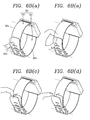
- FIGS. 6A (a)-(d) area conceptual diagrams illustrating a method for processing several control commands defined based on a type of a touch input.
- a touch input sensed in the band unit 302 may be a short touch, a tapping or a long touch applied for a predetermined time or more.
- the short touch, tapping, long touch and the like may be sensed in at least one of the first or second bands 303 and 304.
- a touch input sensed in the band unit may be a drag applied along one direction.
- the touch input may be sensed as a drag applied along the length direction of the band unit in at least the first or second bands 303 and 304. More specifically, at least one of the previously described functions may be performed by a drag applied from the top to the bottom or from the bottom to the top in at least the first or second bands 303 and 304.
- the drag may be sensed as a drag applied along the width direction (direction perpendicular to the length direction) of the band unit in at least the first or second bands 303 and 304. More specifically, at least one of the previously described functions may be performed by a drag applied from the left to the right or from the right to the left.
- At least one of the previously described functions may be performed by a touch input simultaneously applied to two areas among a plurality of areas of the band unit 302.
- the touch input sensed in the band unit 302 may be a short touch, a tapping or a long touch applied for a predetermined time or more, which is simultaneously applied to the first and second areas 305a and 305b (or simultaneously applied to the first and second bands 303 and 304).
- the touch input sensed in the band unit 302 may be a drag simultaneously applied to the first and second bands 303 and 304.
- FIGS. 6B (a) - (d) are a conceptual diagrams illustrating a method for processing several control commands using a third area.
- a user input applied to the third area 305c by the user may be, for example, a touch input or physical input, and at least one of the previously described functions may be performed in response to the user input.
- the touch input sensed in the third area 305c may be a short touch, a tapping or a long touch applied for a predetermined time or more.
- a drag, swipe or the like applied to the third area 305c may be the touch input. More specifically, the short touch, tapping, long touch, drag, swipe and the like may be sensed at a portion corresponding to the third area 305c in the first and second bands 303 and 304. As shown in FIG.
- the controller may process this as a user input.
- At least one of the previously described functions may be performed by a touch input sensed from both surfaces of the band unit in the third area 305c. More specifically, if any of the short touch, tapping, long touch, drag or swipe is applied to the outer surface of the second band 304 and the inner surface (surface facing the wrist when the watch type mobile terminal is worn on the wrist) of the first band 303 when the second band 304 covers the first band 303 in the third area 305c, the controller may process this as a user input.
- At least one of the previously described functions may be performed by a physical input sensed from the band unit in the third area 305c.
- the controller may process this as a user input.
- FIG. 6B (c) it is illustrated that one end of the second band 304 is lifted by the lifting operation.
- the sensing unit may sense that the second band moves relative to the first band, or may sense that a bend occurs in the second band. Accordingly, the sensing unit can recognize that the second band 304 is lifted.
- the controller may process this as a user input (specifically, a flip input).
- FIG. 6B (d) it is illustrated that one end of the second band 304 is flipped. To this end, if the force for lifting the one end of the second band is removed, the second band may be restored to the original position by the self-elasticity thereof.
- the present invention may be applied even when the first band 303 covers the second band 304 in the third area 305c.
- the outer surface of the first band 303 may be an object of the touch input in FIG. 6B (a)
- the inner surface of the second band 304 and the outer surface of the first band 303 may become objects of the touch input in FIG. 6B (b).
- the first band 303 may become an object of the physical input.
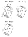
- FIGS. 6C (a) - (c) are a conceptual diagrams illustrating a method for processing several control commands using boundary portions between a plurality of areas.
- At least one of the previously describedfunctions may be performed in response to a touch input applied to a boundary portion of the third area 305c.
- the controller may process, as a user input, a drag or swipe passing through the boundary portion of the third area 305c.
- the sensing unit may sense a direction of the drag or swipe, and different controls (first and second controls) may be performed based on the direction.
- the first control may be performed by a drag or swipe that starts from the third area 305c of the second band 304, passes through the boundary portion and then reaches the first area 305a of the first band 303.
- the second control may be performed by a drag or swipe that starts from the first area 305a of the first band 303, passes through the boundary portion and then reaches the third area 305c.
- the controller may process, as a user input, a drag or swipe that is applied to the boundary portion and progresses along the boundary line. If a drag or swipe is applied along the width direction of the band unit, at least one of the previously described functions may be performed.
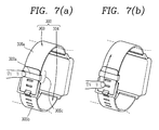
- FIGS. 7 (a) and (b) are conceptual diagrams illustrating a method for processing several control commands using a portion adjacent to the third area.
- the length of the band unit 302 may be adjusted when the watch type mobile terminal is worn on the wrist, and the sizes of the first, second and third areas 305a, 305b and 305c may be changed by the length adjustment.
- the third area 305c may include another portion in addition to the portion at which the first and second bands 303 and 304 are overlapped with each other. Accordingly, the user can easily input a control command when the size of the third area 305c is small.
- the predetermined value is a reference value, and therefore, the portion at which a user input is sensed may be changed depending on the size of the third area 305c.
- the present invention is not necessarily limited thereto, and the example illustrated with reference to FIGS. 7(a) and (b) may be applied to the present invention regardless of the size of the third area 305c.
- a user input with respect to the fastener 302a provided to the band unit 302 may also be processed like the input applied to the third area 305c.
- the sensing unit may sense a touch, push, bend, flip or the like with respect to the fastener 302a, and the controller may perform at least one of the previously described functions in response to the sensing.
- a user input applied to one band covered by another band may also be processed like the input applied to the third area 305c.
- the sensing unit may sense a touch, push, bend, flip or the like with respect to a portion adjacent to the fastener 302a in the first band 303, and the controller may perform at least one of the previously described functions in response to the sensing.
- a continuous touch input in the first and second bands 303 and 304 may also be processed like the input applied to the third area 305c. If one band covering another band (the second band in this example) or the fastener is touched and the band covered by the other band (the first band in this example) is then touched, the controller may perform at least one of the previously described functions in response to the continuous touch.
- the continuous touch input may be a touch applied to the same plane formed by the first band, the third area and the second band.
- the continuous touch input may be a touch applied to a boundary portion at which the first and second bands are engaged with each other. In this case, the touch may be a drag or swipe.
- FIGS. 8A (a) - (c) to 8C (a) and (b) are conceptual diagrams illustrating exemplary embodiments using a third area.
- the controller may execute a predetermined operation mode. For example, if a user input with respect to the third area 305c is sensed, the controller may perform a specific function. The user input with respect to the third area 305c may be linked with the specific function. As an example, a specific application or specific mode may be executed, and an exercise mode (or health mode) is illustrated in the exemplary embodiment.
- the controller executes an exercise mode in the terminal as shown in FIG. 8A (b) .
- An execution screen of the exercise mode may be output on the display unit 351 while the exercise mode is being executed.
- the execution of the operation mode may be performed regardless of whether the display unit 351 is activated. Specifically, the display unit 351 may be non-activated before the exercise mode is executed.
- the controller may control a function performed in the operation mode using an additional user input applied to the band unit.
- an additional user input is applied in the exercise mode, a specific function of recording exercise information, or the like may be performed as shown in FIG. 8A (c) .
- the execution screen of the exercise mode may not be displayed.
- the display unit 351 may be non-activated.
- the exercise information may be provided to the user through voice or vibration.
- the additional user input may be a touch input applied to the third area 305c.
- the present invention is not necessarily limited thereto, and the additional user input may be applied in various manners.
- the additional user input may be applied through a touch with respect to the first or second area 305a or 305b, a voice, or a separately provided physical key.
- the controller performs control related to the specific function.
- the specific function may be paused. That is, the function of recording the exercise information may be paused. In this state, if a touch input is again applied to the third area 305c, the pause may be released, and the function of recording the exercise information may be again performed.
- the controller may perform another control related to the specific function.
- the specific function may be ended.
- the touch input may be a tapping (double tapping or first and second tappings) or touch (double touch or first and second touches) consecutively applied at a time interval.
- the controller can process different control commands based on a kind of a touch input applied to the same area of the band unit. Accordingly, it is possible to perform various controls (execution, pause, end and the like) using the type of the touch input.
- FIGS. 9A (a) and (b) to 9C (a) and (b) are conceptual diagrams illustrating a method for controlling a function based on a type of a touch input.
- an exercise mode is executed. As the exercise mode is executed, an operation of recording exercise information, or the like may be performed. However, before the exercise mode is executed, another mode may be executed, or a sleep mode in which the display unit 351 is non-activated may be executed as described above. Subsequently, if a user's finger simultaneously surrounds another area together with the third area 305c, another mode may be executed. More specifically, if a long touch is applied to the third area 305c, the exercise mode may be executed. If a touch covering at least one portion of the third and first areas 305c and 305a is applied, a blood pressure check mode for measuring a user's blood pressure may be executed.
- the blood pressure check mode may be executed by a touch simultaneously covering another area together with the third area 305c in the watch or sleep mode, rather than the exercise mode.
- the user input applied to the band unit may be any of a plurality of touch inputs applied to the band unit, and each of the plurality of touch inputs may be defined as an execution command with respect to any one of a plurality of operation modes.
- the blood pressure check mode is executed by the touch in the state in which the display unit 351 is non-activated.
- the display unit 351 may continuously maintain the non-activated state.
- the operation may be applied to the execution of the exercise mode.
- the function related to health may be executed while maintaining the non-activated state of the display unit 351.
- blood pressure measurement is performed as shown in FIG. 9B (b) .
- a feedback may be output as shown in FIG. 9B (c) .
- vibration may be generated in the main body, or sound notification or the like may be output.
- the feedback may be generated even in a situation where the blood pressure check mode is not performed any more.
- the feedback may be generated when the band unit is loosened or when the main body or band unit is not contacted with the wrist.
- blood pressure measurement is performed as shown in FIG. 9C (a) . If the blood pressure measurement is completed, a result value may be output on the display unit 351 as shown in FIG. 9C (b) .
- the blood pressure measurement may be performed in the state in which the display unit 351 is non-activated. If the blood pressure measurement is completed, the result value may be output while the display unit 351 is being activated. As another example, a progress bar for notifying a procedure in which the blood pressure measurement is performed may be displayed on the display unit 351. If the blood pressure measurement is completed, a result value may be output.
- the output of the result value may be performed only when the blood pressure is out of a predetermined range. That is, when the blood pressure is not a normal numerical value, the result value may be output while the display unit 351 is being activated in order to notify that the blood pressure is abnormal.
- the result value may be always output, and a separate feedback may be provided when the blood pressure is not the normal numerical value as the measurement result.
- the controller may output sound notification, or may control the band unit to repeatedly tighten the wrist.
- the tightening feeling may be provided by an electric active polymer material contained in the band unit when the supply of power to the electric active polymer material is controlled.
- a result value may be output while the display unit 351 is being activated.
- treatment guidance information may be displayed in which methods for recovering the blood pressure are listed.
- FIGS. 10A (a) - (c) to 10C (a) and (b) are conceptual diagrams illustrating a method for controlling a reproduction application using the band unit.
- a music application is executed as an example of a reproduction application, and music reproduction control icons (e.g., fast-forward, pause/replay, rewind and the like) may be output on the display unit 351.
- music reproduction control icons e.g., fast-forward, pause/replay, rewind and the like
- FIG. 10A (b) If the third area 305c is touched, the production of music, which has been stopped, may be again performed as shown in FIG. 10A (c) .
- a thumbnail for each time zone of the corresponding content may be displayed on the display unit 351.
- the execution of the reproduction application or the performance of the control may be made while the display unit is maintaining the non-activated state.
- control including fast-forward, pause, rewind, previous, next, stop, replay and the like is possible even though the user does not turn on a screen in the state in which content is reproduced.
- the execution of the reproduction application or the performance of the control may be made in a state in which time is output on the display unit.
- the display unit may be in the state in which the display unit is non-activated or in the state in which the time is output on the display unit.
- control related to the reproduction of a content may be performed by a drag or swipe applied to the band unit.
- the sensing unit senses a drag or swipe continued from the third area 305c to the first area 305a in a state in which a content is reproduced
- the controller performs rewinding of the reproduced content.
- the rewinding may be performed while the drag or swipe is being applied.
- FIG. 10B (b) if a user's finger that has applied the drag or swipe is separated from the band unit 302 in the first area 305a, the reproduction is again performed.
- the present invention is not necessarily limited thereto. If the drag or swipe is stopped even though the user's finger is not separated from the band unit 302, the reproduction may be performed.
- the controller performs fast forwarding of the reproduced content.
- Different controls related to the reproduction of the content may be performed based on an area to which the drag or swipe is applied in the band unit 302.
- the reproduction is again performed.
- the present invention is not necessarily limited thereto. If the drag or swipe is stopped even though the user's finger is not separated from the band unit 302, the reproduction may be performed.
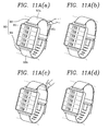
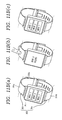
- FIGS. 11A (a) - (d) and 11 B (a) - (c) are conceptual diagrams illustrating a method for controlling screen information using the band unit.
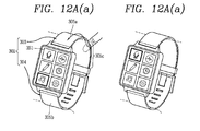
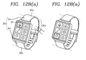
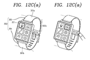
- FIGS. 12A (a) and (b) to 12D (a) and (b) are conceptual diagrams illustrating a method for performing control related to an indicator using the band unit.
- the controller processes a user input applied to the band unit as a control command with respect to the mobile terminal.
- the control related to the display unit is performed by the control command. If the user input is applied to the band unit in a state in which screen information of the display unit is output, at least one portion of the screen information may be changed.
- a list having a plurality of items may be output as an execution screen of a specific function on the display unit 351.
- the band unit In the state in which the list of the specific function is output on the display unit 351, the band unit may be in an activated state. In this state, if one end of one band (the second band in the exemplary example) covering another band, which is a boundary portion of the third area 305c, is pulled and lifted as shown in FIG. 11A (a) , the list may be scrolled toward the top as shown in FIG. 11A (b) .
- the list may be scrolled toward the bottom as shown in FIG. 11A (d) .
- the directions of the scrolling may be applied opposite to each other.
- the moving speed of the list may be changed depending on the intensity and speed of a force pulling and pressing the band unit. As the moving speed of the list is changed, the number of items newly displayed on the display unit 351 may be changed by the scrolling even through an input is applied at the same time.
- a menu having a plurality of menu items may be output as an execution screen of a specific function on the display unit 351.
- an execution screen corresponding to the selected one may be output on the display unit 351 as shown in FIG. 11B (b) .
- the position of the indicator may be moved in response to the user input.
- the user input applied to the band unit is defined to perform the function of a direction key, and accordingly, the position of the indicator is moved.
- graphic images that become objects to be selected are displayed on the display unit 351, and the indicator indicates any one of the graphic images. If a drag or swipe is applied to the band unit 302, the indicator is moved by sequentially indicating the graphic images.
- the indicator may be moved from a graphic image at the bottom to a graphic image at the top by a drag or swipe moving toward the first area 305a from the third area 305c.
- the indicator may be moved from the graphic image at the top to the graphic image at the bottom by a drag or swipe moving toward the second area 305b from the third area 305c.
- the indicator may be moved to the left/right by a drag or swipe moving along a boundary line of the third area 305c.
- the moving direction of the indicator may be determined based on a direction of the drag or swipe. Specifically, as shown in FIG. 12C (b), if the drag or swipe is applied from the left to the right, the indicator may be moved from a graphic image at the left to a graphic image at the right. Although not shown, if the drag or swipe is applied from the right to the left, the indicator may be moved from the graphic image at the right to the graphic image at the left.
- FIGS. 12D (a) and (b) if a short touch or long touch is applied to the third area in a state in which the indicator indicates any one of the graphic images, the indicated graphic image may be selected. A function linked with the indicated graphic image may be performed in response to the selection. The linked function may become an execution screen of the specific function or a response screen with respect to the selection.
- the example of FIGS. 12D (a) and (b) may be independently performed, but may be performed subsequent to the examples of FIGS. 12A (a) and (b) to 12C (a) and (b) .
- FIGS. 13 and 14 (a)-(c) are conceptual diagrams illustrating a method for controlling a notification function using the band unit.
- a user input is applied to the band unit 302, controls the alarm.
- a user input is applied to the band unit 302, thereby controlling the alarm.
- the specific event may include the reception of a message, the reception of an email, the occurrence of a specified schedule, or the like.
- the user input for controlling at least one of the alarms may be a short touch, tapping, long touch, drag, swipe or the like. If a swipe is applied in the width or length direction to the band unit, the sensing unit may sense the swipe, and the controller may release or stop the alarm in response to the sensing. The swipe may be sensed in the third area 305c (see FIG. 4 ) and the first area 305a (see FIG. 4 ).
- the controller may output information related to the alarm in various manners based on a current situation in which the terminal is placed (Here, the type of the information related to the alarm may be varied, and the information may be changed depending on a factor that generates the alarm. For example, when an alarm is generated as a message is received, information related to the alarm may be contents of the message).
- the controller may output information on the alarm using a voice, based on a current position of the terminal.
- the information related to the alarm may be converted into sound information.
- the current position of the terminal may be a vehicle interior.
- the user may have difficulty identifying a display unit through the naked eye due to safety or driving.
- the information related to the alarm is output via the voice corresponding to the user input with respect to the band unit 302, thereby improving user convenience.
- the controller may transmit the information related to the alarm to at least one external device that communicates with the terminal, in response to the user input for controlling the alarm.
- the at least one external device may be a device connected to the terminal via at least one scheme including BluetoothTM, radio frequency identification (RFID), infrared data association (IrDA), ultra wideband (UWB), ZigBeeTM, near field communication (NFC), wireless-fidelity (Wi-Fi), Wi-Fi direct and wireless universal serial bus (wireless USB).
- the external device may be a speaker located in the vehicle or a wireless earphone.
- the controller may again execute notification after a predetermined time with respect to the alarm of the alarm application.
- the controller may perform a function of selecting any of predetermined replay contents (a quick replay function) with respect to the alarms of the message application, the email application or the calendar application.
- Controls responding to alarms may be differently set based on a type of a touch input applied to the band unit.
- the control responding to the alarm may be applied to a case where a call signal is received. Specifically, if a vibration or bell rings when receiving a call signal, a user input is applied to the band unit 302, thereby controlling a function related to call connection. If a swipe is applied to the third and first areas 305c and 305a, the call connection may be rejected. If the swipe is applied to the third and second areas 305c and 305b, the quick replay function may be performed. If the user touches the display unit, the call connection may be performed.
- a control method for responding to an alarm notifying that an event has occurred using the area of the wrist contacted with the band unit may be performed.
- the portion or area of the band unit 302 contacted with the wrist is adjusted, thereby controlling a function related to call connection.
- the quick replay function may be performed in a first state in which the wrist is frequently contacted at a lower position of the band unit 302, and is not contacted with the wrist at an upper position of the band unit 302.
- the first state may be implemented when the user lifts the main body or separates the main body from skin by pressing both the upper and lower positions of the band unit.
- the quick replay function may be performed.
- a function of rejecting a call may be performed in a second state in which the band unit 302 is frequently contacted with the wrist at the upper position of the band unit 302, and is not contacted with the wrist at the lower position of the band unit 302.
- the second state may be implemented when the user lifts the main body or separates the main body from the skin by pressing both the upper and lower positions of the band unit.
- a call rejection function may be performed.
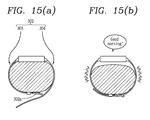
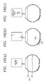
- FIGS. 15 (a) and (b) and 16 (a) - (c) are conceptual diagrams illustrating a method for activating the sensing unit. Exemplary embodiments described with reference to FIGS. 15 (a) and (b) and 16 (a) - (c) may be applied as preconditions of the previously described exemplary embodiments.
- the sensing unit may be activated.
- the band unit 302 is contacted with skin as the watch type mobile terminal is worn on the wrist, the sensing unit may be activated.
- a function of sensing a user input is activated in the band unit by the activation of the sensing unit.
- the controller may generate feedback for notifying the activation of the sensing unit.
- the feedback may be generation of vibration.
- the controller may generate, as sound notification, a predetermined notification sound such as 'Good morning!'.
- the controller may notify that the band unit starts sensing a user input using screen conversion, or the like.
- the activation of the sensing unit may be performed even when the band unit is not contacted with the skin.
- the activation of the sensing unit may be performed when the first and second bands 303 and 304 are fastened to each other by the fastener 302a.
- the sensing unit may be activated.
- the controller decides that the band unit is not wound around the wrist, thereby performing a watch function.
- a user input applied to the band unit in this state may be processed as a control command related to the watch function.
- the control command related to the watch function may be time adjustment, alarm setting, or the like.
- the terminal senses this state.
- the controller decides that the band unit is not wound around the wrist, so that both the sensing unit and the display unit can be non-activated.
- no processing is generated even though a user input is applied to the band unit.
- the sensing unit is activated. If a user input is applied to the band unit, functions except the previously described watch function are performed. If the first and second bands 303 and 304 are connected to each other without any contact of the skin with the band unit, the watch function is basically performed. In this state, the sensing unit is activated. Subsequently, if a user input is applied to the band unit, a specific function or specific application performed when the band unit is wound around the wrist is performed. For example, the sensing unit is activated in the watch function as shown in FIG. 16 (c) . If a touch is applied to the band unit, the exercise mode is executed.
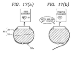
- FIGS. 17 (a) and (b) and 18 (a) and (b) are conceptual diagrams illustrating control methods based on fastening of the band unit.
- the controller processes different control commands based on when a user input is applied in a state in which the first and second bands 303 and 304 are fastened to each other and when a user input is applied in a state in which the fastening between the first and second bands 303 and 304 is released.
- the terminal is formed to sense the state in which the first and second bands 303 and 304 are fastened to each other and the state in which the fastening between the first and second bands 303 and 304 is released. If the fastening between the first and second bands 303 and 304 is released, the controller may stop a function being executed in the state in which the first and second bands 303 and 304 are fastened to each other.
- a blood pressure check mode is executed in the state in which the first and second bands 303 and 304 are fastened to each other. If the fastening between the first and second bands 303 and 304 is released while a living-body recognition sensor is being operated, the living-body recognition sensor is stopped so that the blood pressure measurement is stopped.
- notification information for notifying that the performance of the specific function is impossible may be output.
- the terminal may notify that the performance of another function is possible. For example, the terminal may notify that the measurement of body temperature is possible.
- the activation of the sensing unit is continuously maintainedsuch that a user input with respect to the band unit is possible.
- the user input applied to the band unit in the state in which the fastening is released for example, may be defined as an input for ending the specific function.
- the starting of a specific function may be changed depending on whether the band unit is contacted with or fastened to the skin. If a user input for performing a specific function (e.g., pressure measurement) is input in the state in which the band unit is not contacted with the skin, or the fastening is released, notification information for notifying that the performance of the specific function is impossible may be output.
- the notification information may be output as information using any visual, auditory or tactile manner.
- notification information may be generated based on a user's life pattern. In which the band unit is not contacted with the skin, or the fastening is released even though it is time set to measure blood pressure, notification information for notifying this may be output.
- FIGS. 18 (a) and (b) if fastening between the first and second bands 303 and 304 is released in a state in which the band unit is not contacted with skin, but the sensing unit is activated, a specific function is performed, and if the first and second bands 303 and 304 are fastened to each other, the performance of the specific function is stopped. More specifically, a watch function is performed in a state in which the band unit is not contacted with skin, but the first and second bands 303 and 304 are fastened to each other. If the fastening between the first and second bands 303 and 304 is released, the operation of the watch function is stopped so that the display unit is non-activated.
- the band unit is divided into areas for receiving different control commands, various input methods can be implemented.
- an input method when the watch type mobile terminal is worn may be different from an input method when the watch type mobile terminal is not worn.
- Various embodiments may be implemented using a machine-readable medium having instructions stored thereon for execution by a processor to perform various methods presented herein.
- Examples of possible machine-readable mediums include HDD(Hard Disk Drive), SSD(Solid State Disk), SDD(Silicon Disk Drive), ROM, RAM, CD-ROM, a magnetic tape, a floppy disk, an optical data storage device, the other types of storage mediums presented herein, and combinations thereof.
- the machine-readable medium may be realized in the form of a carrier wave (for example, a transmission over the Internet).
- the processor may include the controller 180 of the mobile terminal.
Landscapes
- Physics & Mathematics (AREA)
- General Physics & Mathematics (AREA)
- Health & Medical Sciences (AREA)
- Life Sciences & Earth Sciences (AREA)
- Biophysics (AREA)
- General Health & Medical Sciences (AREA)
- Physiology (AREA)
- User Interface Of Digital Computer (AREA)
- Telephone Function (AREA)
- Telephone Set Structure (AREA)
Applications Claiming Priority (1)
| Application Number | Priority Date | Filing Date | Title |
|---|---|---|---|
| KR1020140059892A KR101613957B1 (ko) | 2014-05-19 | 2014-05-19 | 와치 타입 이동 단말기 및 그것의 제어방법 |
Publications (3)
| Publication Number | Publication Date |
|---|---|
| EP2955594A2 true EP2955594A2 (fr) | 2015-12-16 |
| EP2955594A3 EP2955594A3 (fr) | 2016-02-17 |
| EP2955594B1 EP2955594B1 (fr) | 2018-09-12 |
Family
ID=52736946
Family Applications (1)
| Application Number | Title | Priority Date | Filing Date |
|---|---|---|---|
| EP15161063.1A Not-in-force EP2955594B1 (fr) | 2014-05-19 | 2015-03-26 | Terminal mobile de type montre et procédé de commande pour le terminal mobile |
Country Status (4)
| Country | Link |
|---|---|
| US (1) | US10180663B2 (fr) |
| EP (1) | EP2955594B1 (fr) |
| KR (1) | KR101613957B1 (fr) |
| CN (1) | CN105099483B (fr) |
Families Citing this family (13)
| Publication number | Priority date | Publication date | Assignee | Title |
|---|---|---|---|---|
| CN107203261B (zh) * | 2016-03-16 | 2022-05-24 | Lg电子株式会社 | 手表型移动终端及其控制方法 |
| JP6758922B2 (ja) * | 2016-06-01 | 2020-09-23 | キヤノン株式会社 | 電子機器及びその制御方法 |
| US10116306B2 (en) | 2016-09-19 | 2018-10-30 | Apple Inc. | Touch and force sensitive rocker switch |
| JP6961451B2 (ja) * | 2017-10-12 | 2021-11-05 | キヤノン株式会社 | 電子機器、その制御方法およびプログラム |
| CN112470103A (zh) * | 2018-07-27 | 2021-03-09 | 深圳市柔宇科技股份有限公司 | 智能手表及其界面控制方法 |
| CN110133992B (zh) * | 2018-09-29 | 2023-09-22 | 广东小天才科技有限公司 | 拍摄方向可调的智能手表 |
| CN110262748A (zh) * | 2019-06-27 | 2019-09-20 | 努比亚技术有限公司 | 可穿戴设备控制方法、可穿戴设备及计算机可读存储介质 |
| USD909369S1 (en) * | 2019-08-07 | 2021-02-02 | Shenzhen DO Intelligent Technology Co., Ltd. | Smart watch |
| JP1681586S (fr) * | 2019-09-12 | 2021-05-24 | ||
| USD1073518S1 (en) | 2021-08-18 | 2025-05-06 | Google Llc | Band connector for a wearable device |
| USD1073517S1 (en) | 2021-08-18 | 2025-05-06 | Google Llc | Band for a wearable device |
| USD1072659S1 (en) | 2021-08-18 | 2025-04-29 | Google Llc | Band with connector for a wearable device |
| CN113805471A (zh) * | 2021-09-03 | 2021-12-17 | 上海豪承信息技术有限公司 | 智能手表和智能手表控制方法 |
Family Cites Families (13)
| Publication number | Priority date | Publication date | Assignee | Title |
|---|---|---|---|---|
| AU575465B2 (en) * | 1985-02-05 | 1988-07-28 | Encrypta Electronics Limited | Apparatus for recording the opening or closing of a closure member |
| JPH11146042A (ja) | 1997-11-06 | 1999-05-28 | Matsushita Electric Ind Co Ltd | 装着型無線通信装置 |
| US20050192044A1 (en) * | 2002-09-09 | 2005-09-01 | Vertu Limited | Cellular radio telephone |
| US8098141B2 (en) * | 2009-02-27 | 2012-01-17 | Nokia Corporation | Touch sensitive wearable band apparatus and method |
| KR101595384B1 (ko) | 2009-07-20 | 2016-02-18 | 엘지전자 주식회사 | 와치형 이동 단말기 |
| KR101626621B1 (ko) | 2009-12-30 | 2016-06-01 | 엘지전자 주식회사 | 원형 디스플레이부를 구비한 이동 통신 단말기의 데이터 제어 방법 및 이를 적용한 이동 통신 단말기 |
| KR101757477B1 (ko) * | 2010-12-09 | 2017-07-12 | 삼성전자주식회사 | 휴대용 통신 장치 |
| US9176530B2 (en) * | 2011-08-17 | 2015-11-03 | Apple Inc. | Bi-stable spring with flexible display |
| US20160011663A1 (en) * | 2012-01-06 | 2016-01-14 | Google Inc. | Motion-Sensed Mechanical Interface Features |
| JP5893456B2 (ja) * | 2012-03-19 | 2016-03-23 | キヤノン株式会社 | 表示制御装置及びその制御方法、プログラム、並びに記憶媒体 |
| US9442578B2 (en) | 2012-08-06 | 2016-09-13 | Lg Electronics Inc. | Capacitive type stylus and mobile terminal comprising the same |
| CN103347111B (zh) | 2013-07-27 | 2016-12-28 | 青岛歌尔声学科技有限公司 | 具有尺寸和重量估测功能的智能移动电子设备 |
| CN103686051A (zh) | 2013-11-15 | 2014-03-26 | 青岛歌尔声学科技有限公司 | 一种便携式通信装置、一种智能手表和一种通信系统 |
-
2014
- 2014-05-19 KR KR1020140059892A patent/KR101613957B1/ko not_active Expired - Fee Related
-
2015
- 2015-02-25 US US14/631,514 patent/US10180663B2/en not_active Expired - Fee Related
- 2015-03-26 EP EP15161063.1A patent/EP2955594B1/fr not_active Not-in-force
- 2015-05-18 CN CN201510253258.7A patent/CN105099483B/zh not_active Expired - Fee Related
Non-Patent Citations (1)
| Title |
|---|
| None |
Also Published As
| Publication number | Publication date |
|---|---|
| EP2955594B1 (fr) | 2018-09-12 |
| CN105099483B (zh) | 2017-12-08 |
| US20150331394A1 (en) | 2015-11-19 |
| CN105099483A (zh) | 2015-11-25 |
| US10180663B2 (en) | 2019-01-15 |
| EP2955594A3 (fr) | 2016-02-17 |
| KR20150133047A (ko) | 2015-11-27 |
| KR101613957B1 (ko) | 2016-04-20 |
Similar Documents
| Publication | Publication Date | Title |
|---|---|---|
| EP2955594B1 (fr) | Terminal mobile de type montre et procédé de commande pour le terminal mobile | |
| EP3239812B1 (fr) | Terminal mobile de type montre | |
| EP3211509B1 (fr) | Dispositif mobile comprenant un stylet, et procédé de fonctionnement associé | |
| KR20160120103A (ko) | 이동 단말기 및 그것의 제어 방법 | |
| KR20160035948A (ko) | 이동 단말기와 그것을 포함하는 시스템 | |
| KR20160113906A (ko) | 이동 단말기 및 그것의 제어 방법 | |
| US20160018890A1 (en) | Haptic guides for a touch-sensitive display | |
| KR20170081391A (ko) | 이동단말기 및 그 제어방법 | |
| EP3133484A1 (fr) | Terminal mobile et son procédé de contrôle | |
| EP3113014B1 (fr) | Terminal mobile et son procédé de commande | |
| CN105706024A (zh) | 使用手腕移动的腕带设备输入 | |
| KR20160143338A (ko) | 이동단말기 및 그 제어방법 | |
| KR20160118803A (ko) | 이동단말기 및 그 제어방법 | |
| KR20160041557A (ko) | 이동단말기 및 그 제어방법 | |
| KR20170076452A (ko) | 이동 단말기 및 그 제어방법 | |
| KR20150112240A (ko) | 이동단말기 및 그 제어방법 | |
| KR20150098115A (ko) | 이동단말기 및 그 제어방법 | |
| US20180260064A1 (en) | Wearable device and control method therefor | |
| KR20170083403A (ko) | 스마트 워치 및 그의 근전도 신호를 이용한 제어방법 | |
| KR20170056300A (ko) | 이동 단말기 및 웨어러블 디바이스 | |
| KR20160016181A (ko) | 이동 단말기 및 그 제어방법 | |
| KR20170074372A (ko) | 이동 단말기 및 그 제어 방법 | |
| KR20170024350A (ko) | 이동단말기 및 그 제어방법 | |
| KR20170024445A (ko) | 이동단말기 및 그 제어방법 | |
| KR20160064756A (ko) | 웨어러블 디바이스 |
Legal Events
| Date | Code | Title | Description |
|---|---|---|---|
| PUAI | Public reference made under article 153(3) epc to a published international application that has entered the european phase |
Free format text: ORIGINAL CODE: 0009012 |
|
| 17P | Request for examination filed |
Effective date: 20150326 |
|
| AK | Designated contracting states |
Kind code of ref document: A2 Designated state(s): AL AT BE BG CH CY CZ DE DK EE ES FI FR GB GR HR HU IE IS IT LI LT LU LV MC MK MT NL NO PL PT RO RS SE SI SK SM TR |
|
| AX | Request for extension of the european patent |
Extension state: BA ME |
|
| PUAL | Search report despatched |
Free format text: ORIGINAL CODE: 0009013 |
|
| AK | Designated contracting states |
Kind code of ref document: A3 Designated state(s): AL AT BE BG CH CY CZ DE DK EE ES FI FR GB GR HR HU IE IS IT LI LT LU LV MC MK MT NL NO PL PT RO RS SE SI SK SM TR |
|
| AX | Request for extension of the european patent |
Extension state: BA ME |
|
| RIC1 | Information provided on ipc code assigned before grant |
Ipc: G04G 21/04 20130101ALI20160111BHEP Ipc: G04G 21/02 20100101AFI20160111BHEP |
|
| RBV | Designated contracting states (corrected) |
Designated state(s): AL AT BE BG CH CY CZ DE DK EE ES FI FR GB GR HR HU IE IS IT LI LT LU LV MC MK MT NL NO PL PT RO RS SE SI SK SM TR |
|
| GRAP | Despatch of communication of intention to grant a patent |
Free format text: ORIGINAL CODE: EPIDOSNIGR1 |
|
| STAA | Information on the status of an ep patent application or granted ep patent |
Free format text: STATUS: GRANT OF PATENT IS INTENDED |
|
| RIC1 | Information provided on ipc code assigned before grant |
Ipc: G04G 21/02 20100101AFI20180328BHEP Ipc: G04G 21/04 20130101ALI20180328BHEP Ipc: G04G 21/08 20100101ALI20180328BHEP |
|
| INTG | Intention to grant announced |
Effective date: 20180418 |
|
| GRAS | Grant fee paid |
Free format text: ORIGINAL CODE: EPIDOSNIGR3 |
|
| GRAA | (expected) grant |
Free format text: ORIGINAL CODE: 0009210 |
|
| STAA | Information on the status of an ep patent application or granted ep patent |
Free format text: STATUS: THE PATENT HAS BEEN GRANTED |
|
| AK | Designated contracting states |
Kind code of ref document: B1 Designated state(s): AL AT BE BG CH CY CZ DE DK EE ES FI FR GB GR HR HU IE IS IT LI LT LU LV MC MK MT NL NO PL PT RO RS SE SI SK SM TR |
|
| REG | Reference to a national code |
Ref country code: GB Ref legal event code: FG4D |
|
| REG | Reference to a national code |
Ref country code: CH Ref legal event code: EP |
|
| REG | Reference to a national code |
Ref country code: IE Ref legal event code: FG4D |
|
| REG | Reference to a national code |
Ref country code: AT Ref legal event code: REF Ref document number: 1041333 Country of ref document: AT Kind code of ref document: T Effective date: 20181015 |
|
| REG | Reference to a national code |
Ref country code: DE Ref legal event code: R096 Ref document number: 602015015940 Country of ref document: DE |
|
| REG | Reference to a national code |
Ref country code: NL Ref legal event code: MP Effective date: 20180912 |
|
| REG | Reference to a national code |
Ref country code: LT Ref legal event code: MG4D |
|
| PG25 | Lapsed in a contracting state [announced via postgrant information from national office to epo] |
Ref country code: LT Free format text: LAPSE BECAUSE OF FAILURE TO SUBMIT A TRANSLATION OF THE DESCRIPTION OR TO PAY THE FEE WITHIN THE PRESCRIBED TIME-LIMIT Effective date: 20180912 Ref country code: FI Free format text: LAPSE BECAUSE OF FAILURE TO SUBMIT A TRANSLATION OF THE DESCRIPTION OR TO PAY THE FEE WITHIN THE PRESCRIBED TIME-LIMIT Effective date: 20180912 Ref country code: SE Free format text: LAPSE BECAUSE OF FAILURE TO SUBMIT A TRANSLATION OF THE DESCRIPTION OR TO PAY THE FEE WITHIN THE PRESCRIBED TIME-LIMIT Effective date: 20180912 Ref country code: BG Free format text: LAPSE BECAUSE OF FAILURE TO SUBMIT A TRANSLATION OF THE DESCRIPTION OR TO PAY THE FEE WITHIN THE PRESCRIBED TIME-LIMIT Effective date: 20181212 Ref country code: RS Free format text: LAPSE BECAUSE OF FAILURE TO SUBMIT A TRANSLATION OF THE DESCRIPTION OR TO PAY THE FEE WITHIN THE PRESCRIBED TIME-LIMIT Effective date: 20180912 Ref country code: GR Free format text: LAPSE BECAUSE OF FAILURE TO SUBMIT A TRANSLATION OF THE DESCRIPTION OR TO PAY THE FEE WITHIN THE PRESCRIBED TIME-LIMIT Effective date: 20181213 Ref country code: NO Free format text: LAPSE BECAUSE OF FAILURE TO SUBMIT A TRANSLATION OF THE DESCRIPTION OR TO PAY THE FEE WITHIN THE PRESCRIBED TIME-LIMIT Effective date: 20181212 |
|
| PG25 | Lapsed in a contracting state [announced via postgrant information from national office to epo] |
Ref country code: HR Free format text: LAPSE BECAUSE OF FAILURE TO SUBMIT A TRANSLATION OF THE DESCRIPTION OR TO PAY THE FEE WITHIN THE PRESCRIBED TIME-LIMIT Effective date: 20180912 Ref country code: AL Free format text: LAPSE BECAUSE OF FAILURE TO SUBMIT A TRANSLATION OF THE DESCRIPTION OR TO PAY THE FEE WITHIN THE PRESCRIBED TIME-LIMIT Effective date: 20180912 Ref country code: LV Free format text: LAPSE BECAUSE OF FAILURE TO SUBMIT A TRANSLATION OF THE DESCRIPTION OR TO PAY THE FEE WITHIN THE PRESCRIBED TIME-LIMIT Effective date: 20180912 |
|
| REG | Reference to a national code |
Ref country code: AT Ref legal event code: MK05 Ref document number: 1041333 Country of ref document: AT Kind code of ref document: T Effective date: 20180912 |
|
| PG25 | Lapsed in a contracting state [announced via postgrant information from national office to epo] |
Ref country code: RO Free format text: LAPSE BECAUSE OF FAILURE TO SUBMIT A TRANSLATION OF THE DESCRIPTION OR TO PAY THE FEE WITHIN THE PRESCRIBED TIME-LIMIT Effective date: 20180912 Ref country code: CZ Free format text: LAPSE BECAUSE OF FAILURE TO SUBMIT A TRANSLATION OF THE DESCRIPTION OR TO PAY THE FEE WITHIN THE PRESCRIBED TIME-LIMIT Effective date: 20180912 Ref country code: AT Free format text: LAPSE BECAUSE OF FAILURE TO SUBMIT A TRANSLATION OF THE DESCRIPTION OR TO PAY THE FEE WITHIN THE PRESCRIBED TIME-LIMIT Effective date: 20180912 Ref country code: IT Free format text: LAPSE BECAUSE OF FAILURE TO SUBMIT A TRANSLATION OF THE DESCRIPTION OR TO PAY THE FEE WITHIN THE PRESCRIBED TIME-LIMIT Effective date: 20180912 Ref country code: EE Free format text: LAPSE BECAUSE OF FAILURE TO SUBMIT A TRANSLATION OF THE DESCRIPTION OR TO PAY THE FEE WITHIN THE PRESCRIBED TIME-LIMIT Effective date: 20180912 Ref country code: PL Free format text: LAPSE BECAUSE OF FAILURE TO SUBMIT A TRANSLATION OF THE DESCRIPTION OR TO PAY THE FEE WITHIN THE PRESCRIBED TIME-LIMIT Effective date: 20180912 Ref country code: NL Free format text: LAPSE BECAUSE OF FAILURE TO SUBMIT A TRANSLATION OF THE DESCRIPTION OR TO PAY THE FEE WITHIN THE PRESCRIBED TIME-LIMIT Effective date: 20180912 Ref country code: ES Free format text: LAPSE BECAUSE OF FAILURE TO SUBMIT A TRANSLATION OF THE DESCRIPTION OR TO PAY THE FEE WITHIN THE PRESCRIBED TIME-LIMIT Effective date: 20180912 Ref country code: IS Free format text: LAPSE BECAUSE OF FAILURE TO SUBMIT A TRANSLATION OF THE DESCRIPTION OR TO PAY THE FEE WITHIN THE PRESCRIBED TIME-LIMIT Effective date: 20190112 |
|
| PG25 | Lapsed in a contracting state [announced via postgrant information from national office to epo] |
Ref country code: PT Free format text: LAPSE BECAUSE OF FAILURE TO SUBMIT A TRANSLATION OF THE DESCRIPTION OR TO PAY THE FEE WITHIN THE PRESCRIBED TIME-LIMIT Effective date: 20190112 Ref country code: SK Free format text: LAPSE BECAUSE OF FAILURE TO SUBMIT A TRANSLATION OF THE DESCRIPTION OR TO PAY THE FEE WITHIN THE PRESCRIBED TIME-LIMIT Effective date: 20180912 Ref country code: SM Free format text: LAPSE BECAUSE OF FAILURE TO SUBMIT A TRANSLATION OF THE DESCRIPTION OR TO PAY THE FEE WITHIN THE PRESCRIBED TIME-LIMIT Effective date: 20180912 |
|
| REG | Reference to a national code |
Ref country code: DE Ref legal event code: R097 Ref document number: 602015015940 Country of ref document: DE |
|
| PLBE | No opposition filed within time limit |
Free format text: ORIGINAL CODE: 0009261 |
|
| STAA | Information on the status of an ep patent application or granted ep patent |
Free format text: STATUS: NO OPPOSITION FILED WITHIN TIME LIMIT |
|
| PG25 | Lapsed in a contracting state [announced via postgrant information from national office to epo] |
Ref country code: DK Free format text: LAPSE BECAUSE OF FAILURE TO SUBMIT A TRANSLATION OF THE DESCRIPTION OR TO PAY THE FEE WITHIN THE PRESCRIBED TIME-LIMIT Effective date: 20180912 |
|
| 26N | No opposition filed |
Effective date: 20190613 |
|
| PG25 | Lapsed in a contracting state [announced via postgrant information from national office to epo] |
Ref country code: SI Free format text: LAPSE BECAUSE OF FAILURE TO SUBMIT A TRANSLATION OF THE DESCRIPTION OR TO PAY THE FEE WITHIN THE PRESCRIBED TIME-LIMIT Effective date: 20180912 |
|
| PG25 | Lapsed in a contracting state [announced via postgrant information from national office to epo] |
Ref country code: MC Free format text: LAPSE BECAUSE OF FAILURE TO SUBMIT A TRANSLATION OF THE DESCRIPTION OR TO PAY THE FEE WITHIN THE PRESCRIBED TIME-LIMIT Effective date: 20180912 |
|
| REG | Reference to a national code |
Ref country code: CH Ref legal event code: PL |
|
| GBPC | Gb: european patent ceased through non-payment of renewal fee |
Effective date: 20190326 |
|
| PG25 | Lapsed in a contracting state [announced via postgrant information from national office to epo] |
Ref country code: LU Free format text: LAPSE BECAUSE OF NON-PAYMENT OF DUE FEES Effective date: 20190326 |
|
| REG | Reference to a national code |
Ref country code: BE Ref legal event code: MM Effective date: 20190331 |
|
| PG25 | Lapsed in a contracting state [announced via postgrant information from national office to epo] |
Ref country code: CH Free format text: LAPSE BECAUSE OF NON-PAYMENT OF DUE FEES Effective date: 20190331 Ref country code: LI Free format text: LAPSE BECAUSE OF NON-PAYMENT OF DUE FEES Effective date: 20190331 Ref country code: IE Free format text: LAPSE BECAUSE OF NON-PAYMENT OF DUE FEES Effective date: 20190326 Ref country code: GB Free format text: LAPSE BECAUSE OF NON-PAYMENT OF DUE FEES Effective date: 20190326 |
|
| PG25 | Lapsed in a contracting state [announced via postgrant information from national office to epo] |
Ref country code: BE Free format text: LAPSE BECAUSE OF NON-PAYMENT OF DUE FEES Effective date: 20190331 |
|
| PG25 | Lapsed in a contracting state [announced via postgrant information from national office to epo] |
Ref country code: TR Free format text: LAPSE BECAUSE OF FAILURE TO SUBMIT A TRANSLATION OF THE DESCRIPTION OR TO PAY THE FEE WITHIN THE PRESCRIBED TIME-LIMIT Effective date: 20180912 |
|
| PGFP | Annual fee paid to national office [announced via postgrant information from national office to epo] |
Ref country code: DE Payment date: 20200211 Year of fee payment: 6 |
|
| PG25 | Lapsed in a contracting state [announced via postgrant information from national office to epo] |
Ref country code: MT Free format text: LAPSE BECAUSE OF NON-PAYMENT OF DUE FEES Effective date: 20190326 |
|
| PGFP | Annual fee paid to national office [announced via postgrant information from national office to epo] |
Ref country code: FR Payment date: 20200213 Year of fee payment: 6 |
|
| PG25 | Lapsed in a contracting state [announced via postgrant information from national office to epo] |
Ref country code: CY Free format text: LAPSE BECAUSE OF FAILURE TO SUBMIT A TRANSLATION OF THE DESCRIPTION OR TO PAY THE FEE WITHIN THE PRESCRIBED TIME-LIMIT Effective date: 20180912 |
|
| PG25 | Lapsed in a contracting state [announced via postgrant information from national office to epo] |
Ref country code: HU Free format text: LAPSE BECAUSE OF FAILURE TO SUBMIT A TRANSLATION OF THE DESCRIPTION OR TO PAY THE FEE WITHIN THE PRESCRIBED TIME-LIMIT; INVALID AB INITIO Effective date: 20150326 |
|
| REG | Reference to a national code |
Ref country code: DE Ref legal event code: R119 Ref document number: 602015015940 Country of ref document: DE |
|
| PG25 | Lapsed in a contracting state [announced via postgrant information from national office to epo] |
Ref country code: DE Free format text: LAPSE BECAUSE OF NON-PAYMENT OF DUE FEES Effective date: 20211001 Ref country code: FR Free format text: LAPSE BECAUSE OF NON-PAYMENT OF DUE FEES Effective date: 20210331 |
|
| PG25 | Lapsed in a contracting state [announced via postgrant information from national office to epo] |
Ref country code: MK Free format text: LAPSE BECAUSE OF FAILURE TO SUBMIT A TRANSLATION OF THE DESCRIPTION OR TO PAY THE FEE WITHIN THE PRESCRIBED TIME-LIMIT Effective date: 20180912 |