EP2955810A1 - Batteriesteuerungsvorrichtung, batteriesteuerungassistenzvorrichtung, batteriesteuerungssystem, batteriesteuerungsverfahren, batteriesteuerungassistenzverfahren und aufzeichnungsmedium - Google Patents
Batteriesteuerungsvorrichtung, batteriesteuerungassistenzvorrichtung, batteriesteuerungssystem, batteriesteuerungsverfahren, batteriesteuerungassistenzverfahren und aufzeichnungsmedium Download PDFInfo
- Publication number
- EP2955810A1 EP2955810A1 EP14748508.0A EP14748508A EP2955810A1 EP 2955810 A1 EP2955810 A1 EP 2955810A1 EP 14748508 A EP14748508 A EP 14748508A EP 2955810 A1 EP2955810 A1 EP 2955810A1
- Authority
- EP
- European Patent Office
- Prior art keywords
- battery
- information
- control
- state
- power system
- Prior art date
- Legal status (The legal status is an assumption and is not a legal conclusion. Google has not performed a legal analysis and makes no representation as to the accuracy of the status listed.)
- Withdrawn
Links
Images







Classifications
-
- G—PHYSICS
- G05—CONTROLLING; REGULATING
- G05F—SYSTEMS FOR REGULATING ELECTRIC OR MAGNETIC VARIABLES
- G05F1/00—Automatic systems in which deviations of an electric quantity from one or more predetermined values are detected at the output of the system and fed back to a device within the system to restore the detected quantity to its predetermined value or values, i.e. retroactive systems
- G05F1/66—Regulating electric power
-
- G—PHYSICS
- G05—CONTROLLING; REGULATING
- G05F—SYSTEMS FOR REGULATING ELECTRIC OR MAGNETIC VARIABLES
- G05F1/00—Automatic systems in which deviations of an electric quantity from one or more predetermined values are detected at the output of the system and fed back to a device within the system to restore the detected quantity to its predetermined value or values, i.e. retroactive systems
- G05F1/10—Regulating voltage or current
- G05F1/625—Regulating voltage or current wherein it is irrelevant whether the variable actually regulated is AC or DC
-
- H—ELECTRICITY
- H02—GENERATION; CONVERSION OR DISTRIBUTION OF ELECTRIC POWER
- H02J—ELECTRIC POWER NETWORKS; CIRCUIT ARRANGEMENTS OR SYSTEMS FOR SUPPLYING OR DISTRIBUTING ELECTRIC POWER; SYSTEMS FOR STORING ELECTRIC ENERGY
- H02J13/00—Circuit arrangements for providing remote monitoring or remote control of equipment in a power distribution network
- H02J13/12—Monitoring network conditions, e.g. electrical magnitudes or operational status
-
- H—ELECTRICITY
- H02—GENERATION; CONVERSION OR DISTRIBUTION OF ELECTRIC POWER
- H02J—ELECTRIC POWER NETWORKS; CIRCUIT ARRANGEMENTS OR SYSTEMS FOR SUPPLYING OR DISTRIBUTING ELECTRIC POWER; SYSTEMS FOR STORING ELECTRIC ENERGY
- H02J13/00—Circuit arrangements for providing remote monitoring or remote control of equipment in a power distribution network
- H02J13/18—Circuit arrangements for providing remote monitoring or remote control of equipment in a power distribution network characterised by the remotely-controlled equipment, e.g. converters or transformers
- H02J13/333—Circuit arrangements for providing remote monitoring or remote control of equipment in a power distribution network characterised by the remotely-controlled equipment, e.g. converters or transformers the equipment forming part of substations
-
- H—ELECTRICITY
- H02—GENERATION; CONVERSION OR DISTRIBUTION OF ELECTRIC POWER
- H02J—ELECTRIC POWER NETWORKS; CIRCUIT ARRANGEMENTS OR SYSTEMS FOR SUPPLYING OR DISTRIBUTING ELECTRIC POWER; SYSTEMS FOR STORING ELECTRIC ENERGY
- H02J3/00—Circuit arrangements for AC mains or AC distribution networks
- H02J3/28—Arrangements for balancing of the load in networks by storage of energy
- H02J3/32—Arrangements for balancing of the load in networks by storage of energy using batteries or super capacitors with converting means
-
- H—ELECTRICITY
- H02—GENERATION; CONVERSION OR DISTRIBUTION OF ELECTRIC POWER
- H02J—ELECTRIC POWER NETWORKS; CIRCUIT ARRANGEMENTS OR SYSTEMS FOR SUPPLYING OR DISTRIBUTING ELECTRIC POWER; SYSTEMS FOR STORING ELECTRIC ENERGY
- H02J3/00—Circuit arrangements for AC mains or AC distribution networks
- H02J3/38—Arrangements for feeding a single network from two or more generators or sources in parallel; Arrangements for feeding already energised networks from additional generators or sources in parallel
- H02J3/381—Dispersed generators
-
- H—ELECTRICITY
- H02—GENERATION; CONVERSION OR DISTRIBUTION OF ELECTRIC POWER
- H02J—ELECTRIC POWER NETWORKS; CIRCUIT ARRANGEMENTS OR SYSTEMS FOR SUPPLYING OR DISTRIBUTING ELECTRIC POWER; SYSTEMS FOR STORING ELECTRIC ENERGY
- H02J7/00—Circuit arrangements for charging or discharging batteries or for supplying loads from batteries
- H02J7/865—Battery or charger load switching, e.g. concurrent charging and load supply
-
- H—ELECTRICITY
- H02—GENERATION; CONVERSION OR DISTRIBUTION OF ELECTRIC POWER
- H02J—ELECTRIC POWER NETWORKS; CIRCUIT ARRANGEMENTS OR SYSTEMS FOR SUPPLYING OR DISTRIBUTING ELECTRIC POWER; SYSTEMS FOR STORING ELECTRIC ENERGY
- H02J2101/00—Supply or distribution of decentralised, dispersed or local electric power generation
- H02J2101/20—Dispersed power generation using renewable energy sources
-
- H—ELECTRICITY
- H02—GENERATION; CONVERSION OR DISTRIBUTION OF ELECTRIC POWER
- H02J—ELECTRIC POWER NETWORKS; CIRCUIT ARRANGEMENTS OR SYSTEMS FOR SUPPLYING OR DISTRIBUTING ELECTRIC POWER; SYSTEMS FOR STORING ELECTRIC ENERGY
- H02J2101/00—Supply or distribution of decentralised, dispersed or local electric power generation
- H02J2101/20—Dispersed power generation using renewable energy sources
- H02J2101/22—Solar energy
-
- Y—GENERAL TAGGING OF NEW TECHNOLOGICAL DEVELOPMENTS; GENERAL TAGGING OF CROSS-SECTIONAL TECHNOLOGIES SPANNING OVER SEVERAL SECTIONS OF THE IPC; TECHNICAL SUBJECTS COVERED BY FORMER USPC CROSS-REFERENCE ART COLLECTIONS [XRACs] AND DIGESTS
- Y02—TECHNOLOGIES OR APPLICATIONS FOR MITIGATION OR ADAPTATION AGAINST CLIMATE CHANGE
- Y02E—REDUCTION OF GREENHOUSE GAS [GHG] EMISSIONS, RELATED TO ENERGY GENERATION, TRANSMISSION OR DISTRIBUTION
- Y02E10/00—Energy generation through renewable energy sources
- Y02E10/50—Photovoltaic [PV] energy
- Y02E10/56—Power conversion systems, e.g. maximum power point trackers
-
- Y—GENERAL TAGGING OF NEW TECHNOLOGICAL DEVELOPMENTS; GENERAL TAGGING OF CROSS-SECTIONAL TECHNOLOGIES SPANNING OVER SEVERAL SECTIONS OF THE IPC; TECHNICAL SUBJECTS COVERED BY FORMER USPC CROSS-REFERENCE ART COLLECTIONS [XRACs] AND DIGESTS
- Y02—TECHNOLOGIES OR APPLICATIONS FOR MITIGATION OR ADAPTATION AGAINST CLIMATE CHANGE
- Y02E—REDUCTION OF GREENHOUSE GAS [GHG] EMISSIONS, RELATED TO ENERGY GENERATION, TRANSMISSION OR DISTRIBUTION
- Y02E10/00—Energy generation through renewable energy sources
- Y02E10/70—Wind energy
- Y02E10/76—Power conversion electric or electronic aspects
-
- Y—GENERAL TAGGING OF NEW TECHNOLOGICAL DEVELOPMENTS; GENERAL TAGGING OF CROSS-SECTIONAL TECHNOLOGIES SPANNING OVER SEVERAL SECTIONS OF THE IPC; TECHNICAL SUBJECTS COVERED BY FORMER USPC CROSS-REFERENCE ART COLLECTIONS [XRACs] AND DIGESTS
- Y02—TECHNOLOGIES OR APPLICATIONS FOR MITIGATION OR ADAPTATION AGAINST CLIMATE CHANGE
- Y02E—REDUCTION OF GREENHOUSE GAS [GHG] EMISSIONS, RELATED TO ENERGY GENERATION, TRANSMISSION OR DISTRIBUTION
- Y02E40/00—Technologies for an efficient electrical power generation, transmission or distribution
- Y02E40/70—Smart grids as climate change mitigation technology in the energy generation sector
-
- Y—GENERAL TAGGING OF NEW TECHNOLOGICAL DEVELOPMENTS; GENERAL TAGGING OF CROSS-SECTIONAL TECHNOLOGIES SPANNING OVER SEVERAL SECTIONS OF THE IPC; TECHNICAL SUBJECTS COVERED BY FORMER USPC CROSS-REFERENCE ART COLLECTIONS [XRACs] AND DIGESTS
- Y02—TECHNOLOGIES OR APPLICATIONS FOR MITIGATION OR ADAPTATION AGAINST CLIMATE CHANGE
- Y02E—REDUCTION OF GREENHOUSE GAS [GHG] EMISSIONS, RELATED TO ENERGY GENERATION, TRANSMISSION OR DISTRIBUTION
- Y02E60/00—Enabling technologies; Technologies with a potential or indirect contribution to GHG emissions mitigation
-
- Y—GENERAL TAGGING OF NEW TECHNOLOGICAL DEVELOPMENTS; GENERAL TAGGING OF CROSS-SECTIONAL TECHNOLOGIES SPANNING OVER SEVERAL SECTIONS OF THE IPC; TECHNICAL SUBJECTS COVERED BY FORMER USPC CROSS-REFERENCE ART COLLECTIONS [XRACs] AND DIGESTS
- Y02—TECHNOLOGIES OR APPLICATIONS FOR MITIGATION OR ADAPTATION AGAINST CLIMATE CHANGE
- Y02E—REDUCTION OF GREENHOUSE GAS [GHG] EMISSIONS, RELATED TO ENERGY GENERATION, TRANSMISSION OR DISTRIBUTION
- Y02E70/00—Other energy conversion or management systems reducing GHG emissions
- Y02E70/30—Systems combining energy storage with energy generation of non-fossil origin
-
- Y—GENERAL TAGGING OF NEW TECHNOLOGICAL DEVELOPMENTS; GENERAL TAGGING OF CROSS-SECTIONAL TECHNOLOGIES SPANNING OVER SEVERAL SECTIONS OF THE IPC; TECHNICAL SUBJECTS COVERED BY FORMER USPC CROSS-REFERENCE ART COLLECTIONS [XRACs] AND DIGESTS
- Y04—INFORMATION OR COMMUNICATION TECHNOLOGIES HAVING AN IMPACT ON OTHER TECHNOLOGY AREAS
- Y04S—SYSTEMS INTEGRATING TECHNOLOGIES RELATED TO POWER NETWORK OPERATION, COMMUNICATION OR INFORMATION TECHNOLOGIES FOR IMPROVING THE ELECTRICAL POWER GENERATION, TRANSMISSION, DISTRIBUTION, MANAGEMENT OR USAGE, i.e. SMART GRIDS
- Y04S10/00—Systems supporting electrical power generation, transmission or distribution
- Y04S10/12—Monitoring or controlling equipment for energy generation units, e.g. distributed energy generation [DER] or load-side generation
- Y04S10/123—Monitoring or controlling equipment for energy generation units, e.g. distributed energy generation [DER] or load-side generation the energy generation units being or involving renewable energy sources
-
- Y—GENERAL TAGGING OF NEW TECHNOLOGICAL DEVELOPMENTS; GENERAL TAGGING OF CROSS-SECTIONAL TECHNOLOGIES SPANNING OVER SEVERAL SECTIONS OF THE IPC; TECHNICAL SUBJECTS COVERED BY FORMER USPC CROSS-REFERENCE ART COLLECTIONS [XRACs] AND DIGESTS
- Y04—INFORMATION OR COMMUNICATION TECHNOLOGIES HAVING AN IMPACT ON OTHER TECHNOLOGY AREAS
- Y04S—SYSTEMS INTEGRATING TECHNOLOGIES RELATED TO POWER NETWORK OPERATION, COMMUNICATION OR INFORMATION TECHNOLOGIES FOR IMPROVING THE ELECTRICAL POWER GENERATION, TRANSMISSION, DISTRIBUTION, MANAGEMENT OR USAGE, i.e. SMART GRIDS
- Y04S10/00—Systems supporting electrical power generation, transmission or distribution
- Y04S10/14—Energy storage units
-
- Y—GENERAL TAGGING OF NEW TECHNOLOGICAL DEVELOPMENTS; GENERAL TAGGING OF CROSS-SECTIONAL TECHNOLOGIES SPANNING OVER SEVERAL SECTIONS OF THE IPC; TECHNICAL SUBJECTS COVERED BY FORMER USPC CROSS-REFERENCE ART COLLECTIONS [XRACs] AND DIGESTS
- Y04—INFORMATION OR COMMUNICATION TECHNOLOGIES HAVING AN IMPACT ON OTHER TECHNOLOGY AREAS
- Y04S—SYSTEMS INTEGRATING TECHNOLOGIES RELATED TO POWER NETWORK OPERATION, COMMUNICATION OR INFORMATION TECHNOLOGIES FOR IMPROVING THE ELECTRICAL POWER GENERATION, TRANSMISSION, DISTRIBUTION, MANAGEMENT OR USAGE, i.e. SMART GRIDS
- Y04S10/00—Systems supporting electrical power generation, transmission or distribution
- Y04S10/30—State monitoring, e.g. fault, temperature monitoring, insulator monitoring, corona discharge
Definitions
- the present invention relates to a battery control system, a battery control device, a battery control support device, a battery control method, a battery control support method, and a program, and particularly relates to a battery control system, a battery control device, a battery control support device, a battery control method, a battery control support method, and a program that control discharge or charge of a battery connected to a power system.
- a method for adjusting power demand and supply a method has been adopted, which mainly uses the output control function of thermal power generation equipment of a thermal electric power plant, and properly combines an output adjustment function of pumping-up hydraulic power generation.
- an energy storage such as “a storage battery” that interconnects to the distribution network of a power system, and is expected to come into widespread use from now on.
- Patent Literature 1 describes a power system control method that adjusts power demand and supply by using a secondary battery (ES) in a consumer side.
- ES secondary battery
- a power system control device acquires an amount of charge in a secondary battery, and further acquires a schedule of power supply to a power system that is generated based on a power demand forecast from a central power supply instruction office or the like.
- the power system control device determines an operation schedule of the secondary battery based on the amount of charge in the secondary battery and the power supply schedule.
- the power system control device determines the operation schedule of the secondary battery
- the power system control device transmits the operation schedule to a secondary battery control system that controls the operation of the secondary battery.
- the secondary battery control system When the secondary battery control system receives the operation schedule from the power system control device, the secondary battery control system controls charge and discharge of the secondary battery in accordance with the operation schedule, irrespective of the actual state of the power system.
- Patent Literature 2 describes a system in which a central controller acquires state of charge information of a plurality of battery cells sampled at the same point of time via a local monitor and an upper controller.
- the amount of power supplied from a renewable power sourse to a power system varies according to charges, over a short period of time, in the weather conditions.
- the amount of power that is supplied varies as a result of small clouds that pass in front of the sun.
- Patent Literature 1 it is difficult, in practice, to have the operation schedule (control information) of the secondary battery that is created by the power system control device that is an upper device, reflect chandes, in the amount of supplied power, that will occur due to changes, over a short period of time, in weather conditions.
- Patent Literature 1 has the problem of being unable to cope with the actual variation state of the power system, in which the control information from the upper device is not reflected.
- An object of the present invention is to provide a battery control system, a battery control device, a battery control support device, a battery control method, a battery control support method and a program that can solve the above-described problem.
- a battery control device is a battery control device controlling an operation of a battery connected to a power system, the device includes:
- a battery control support device is a battery control support device communicating with a battery control device controlling an operation of a battery connected to a power system, the device includes:
- a battery control system is a battery control system including a first control device that controls an operation of a battery connected to a power system, and a second control device that communicates with the first control device,
- a battery control method is a battery control method that is performed by a battery control device that controls an operation of a battery connected to a power system, wherein the method includes;
- a battery control support method is a battery control support method performed by a battery control support device that communicates with a battery control device that controls an operation of a battery connected to a power system, wherein the method includes;
- a battery control method is a battery control method that is performed by a battery control system including a first control device that controls an operation of a battery connected to a power system, and a second control device that communicates with the first control device, wherein
- a recording medium of the present invention is a computer-readable recording medium recording a program for causing a computer to execute:
- a recording medium of the present invention is a computer-readable recording medium recording a program for causing a computer to execute:
- the first control device controls the operation of the battery based on the operation control information provided from the second control device (the battery control support device) and the state of the power system, and thereby it becomes possible to adjust the operation of the battery in response to an actual change in the state of the power system while following the operation control information.
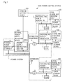
- Figure 1 is a diagram showing power control system 1000 that adopts a battery control system of a first exemplary embodiment of the present invention.
- power control system 1000 includes power system 1, photovoltaic power generator 2, N (N is an integer that is 1 or larger) power storage devices 3, N local charge and discharge devices 100, storage battery SCADA (Supervisory Control And Data Acquisition) 200, and power supply instruction section 300A in central power supply instruction office 300.
- the power system 1 includes thermal power generation equipment 4, distribution transformer 5 and distribution line 6. Note that photovoltaic power generator 2 may be included in power system 1.
- the battery control system includes N of local charge and discharge devices 100, and storage battery SCADA 200.
- Power control system 1000 limits variation in system frequency that result from changes in the amount of power generated by photovoltaic power generator 2, due to whether conditions, which is of concern to power system 1, to which photovoltaic power generator 2 is interconnected, by controlling a power generation operation of thermal power generation equipment 4 and charge and discharge operations of N of power storage devices 3.
- Power system 1 is a system for supplying power to load 7 for use by consumers.
- Power system 1 also includes other devices (for example, a switch, an upper electric transformer, an SVR (Step Voltage Regulator) and a pole transformer), but for simplification of explanation, these devices are omitted.
- Photovoltaic power generator 2 is an example of a renewable power source.
- the renewable power sources are not limited to a photovoltaic power generator and alternative renewable power sources can be used.
- a wind power generator a hydroelectric generator (including a small hydroelectric generator that generates power of 1,000 kilowatts or less), a geothermal power generator, or a power source in which these power generators coexist may be used.
- Power storage device 3 is an example of a battery (a storage battery), and can be, for example, a lithium ion battery, a nickel-metal hydride battery, a sodium-sulfur battery, or a redox flow battery.
- N power storage devices 3 are in one-to-one correspondence with N local charge and discharge devices 100.
- Power storage device 3 may be contained in corresponding local charge and discharge device 100, or does not have to be contained in corresponding local charge and discharge device 100.
- respective power storage devices 3 are contained in corresponding local charge and discharge devices 100 (see Figure 2 ).
- Respective local charge and discharge devices 100 control charge and discharge operations of corresponding power storage devices 3.
- Storage battery SCADA 200 manages respective local charge and discharge devices 100 and respective power storage devices 3.
- Power supply instruction section 300A adjusts a power generation operation of thermal power generation equipment 4, and charge and discharge operations of N of power storage devices 3, and thereby limits a variation in the system frequency.
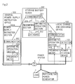
- Figure 2 is a diagram showing examples of local charge and discharge device 100, storage battery SCADA 200 and power supply instruction section 300A.
- Figure 2 those having the same configurations as those shown in Figure 1 are assigned with the same reference signs.
- Figure 2 shows one local charge and discharge device 100 containing one power storage device 3 among N of power storage devices 3 and N of local charge and discharge devices 100.
- Local charge and discharge device 100 is an example of a first control device or a battery control device. Local charge and discharge device 100 controls an operation of power storage device 3 that is connected to power system 1. Local charge and discharge device 100 includes detector 101, communicator 102, frequency meter 103 and arithmetic operation section 104.
- Detector 101 is an example of first detection means (detection means). Detector 101 detects SOC (State of Charge) of power storage device 3.
- SOC State of Charge
- the SOC of power storage device 3 takes a value within a range of 0 to 1.
- the SOC of power storage device 3 is an example of battery-related information that indicates a state of power storage device 3 or state information, or battery information for determining a chargeable and dischargeable capacity of power storage device 3. Note that the battery-related information, the state information and the battery information are not limited to the SOC of power storage device 3 and alternative information can be used. For example, a cell temperature, a current amount and a voltage of power storage device 3 may be used.
- Communicator 102 is an example of first communicating means. Communicator 102 communicates with storage battery SCADA 200.
- Frequency meter 103 is an example of second detection means.
- Frequency meter 103 detects a system frequency (a system frequency of power system 1). The system frequency varies in accordance with a power demand and supply balance state. The system frequency is an example of a state of the power system. Note that frequency meter 103 may be inside or outside local charge and discharge device 100.
- Arithmetic operation section 104 is an example of control means.
- Arithmetic operation section 104 executes an information acquiring operation (transmission and reception processing) of obtaining allotment information that shows allotment for controlling the balance between power demand and supply from storage battery SCADA 200, and a control operation (battery operation control processing) to control a charge and discharge operation of power storage device 3 by using the allotment information.
- the allotment information is information that relates to the charge and discharge operation of power storage device 3 and that is allotted to local charge and discharge device 100 and power storage device 3 in order to limit a variation in the system frequency.
- Arithmetic operation section 104 repeatedly executes the information acquiring operation at time intervals, and repeatedly executes the control operation at time intervals shorter than the time intervals of the information acquiring operation.
- Period T is an example of a predetermined time interval.
- period T and period T 1 are not limited to one minute and 0.1 seconds, and period T can be longer than period T 1 .
- both or any one of the operation time intervals of the information acquiring operation and the operation time interval of the control operation do not have to be fixed, and the shortest time among the respective operation time intervals of the information acquiring operation can be longer than the longest time among the respective operation time intervals of the control operation.
- arithmetic operation section 104 may execute the information acquiring operation in response to the information request that requests SOC from storage battery SCADA 200, or may autonomously execute the information acquiring operation.
- Arithmetic operation section 104 transmits the SOC of power storage device 3 detected by detector 101 to storage battery SCADA 200 from communicator 102, together with identification information (hereinafter, called "ID") of power storage device 3.
- ID identification information
- Storage battery SCADA 200 identifies power storage device 3, from which the SOC is reported, by using the ID transmitted with the SOC of power storage device 3.
- Communicator 102 transmits the SOC and ID of power storage device 3 to storage battery SCADA 200, and thereafter receives allotment information from storage battery SCADA 200.
- the allotment information is set in accordance with the SOC of power storage device 3 and an imbalance state of demand and supply in power.
- allotment coefficient K, and maximum value ⁇ f max of an integral value of a frequency deviation are used, as the allotment information.
- Allotment coefficient K is an example of operation control information, and becomes larger as an allotment ratio to power storage device 3 becomes higher.
- Maximum value ⁇ f max of the integral value of the frequency deviation is used as a threshold value of a deviation amount with respect to a reference frequency (for example, 50 Hz) of a system frequency. Note that the reference frequency of the system frequency is stored in arithmetic operation section 104.
- Arithmetic operation section 104 controls the charge and discharge operation of power storage device 3 based on the system frequency of power system 1 detected by frequency meter 103, and based on the allotment information received by communicator 102.
- arithmetic operation section 104 may control the charge and discharge operation of power storage device 3 based on the SOC of power storage device 3, in addition to the system frequency of power system 1 detected by frequency meter 103, and the allotment information received by communicator 102.
- arithmetic operation section 104 may use the system frequency of power system 1 received from outside instead of the system frequency of power system 1 detected by frequency meter 103. In this case, arithmetic operation section 104 also functions as second detection means.
- Arithmetic operation section 104 obtains integral value ⁇ f of a frequency deviation that is the deviation amount of the system frequency of power system 1 with respect to the reference frequency of the system frequency. Arithmetic operation section 104 controls the charge and discharge operation of power storage device 3 by using allotment coefficient K and integral value ⁇ f of the frequency deviation, when an absolute value of integral value ⁇ f of the frequency deviation is maximum value ⁇ f max of the integral values of the frequency deviations, or smaller.
- arithmetic operation section 104 controls the charge and discharge operation of power storage device 3 by using allotment coefficient K and maximum value ⁇ f max of the integral values of the frequency deviations.
- Storage battery SCADA 200 is an example of a second control device or a battery control support device.
- Storage battery SCADA 200 has N of local charge and discharge devices 100 and N of power storage devices 3 under control.
- Storage battery SCADA 200 includes communicator 201, database 202, recognition section 203, and arithmetic operation section 204.
- Communicator 201 is an example of second communication means. Communicator 201 communicates with respective local charge and discharge devices 100 and power supply instruction section 300A. For example, communicator 201 receives the SOC and ID of power storage device 3 from each of local charge and discharge devices 100.
- Database 202 retains a storage battery distribution factor curve that is used to determine a chargeable and dischargeable capacity of power storage device 3 from the SOC of power storage device 3 received by communicator 201. Furthermore, database 202 also retains rated output P(n) of each of power storage devices 3 that is used to determine the chargeable and dischargeable capacity. Note that as rated output P(n) of power storage device 3, the rated output of an unillustrated power convertor (an AC/DC converter) that is connected to power storage device 3 is used.
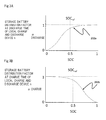
- Figures 3A and 3B each show an example of the storage battery distribution factor curve.
- Figure 3A shows an example of storage battery distribution factor curve 202a at the time of discharge
- Figure 3B shows an example of storage battery distribution factor curve 202b at the time of charge.
- Recognition section 203 is an example of recognition means. Recognition section 203 recognizes power amounts (hereinafter, called “allotted power amounts") that are allotted to power storage devices 3 under control of storage battery SCADA 200 in order to adjust the power amount in power system 1. The allotted power amount is an example of a situation of the power system.
- Recognition section 203 derives total adjustable capacity P ES showing the chargeable and dischargeable capacity of a storage battery group formed by N of power storage devices 3 from the SOC of N of power storage devices 3 by using the storage battery distribution factor curves in database 202.
- Total adjustable capacity P ES is an example of notification information.
- Recognition section 203 transmits total adjustable capacity P ES to power supply instruction section 300A from communicator 201, and thereafter, receives allotted power amount information showing the allotted power amount reflecting total adjustable capacity P ES from power dispatching instruction section 300A via communicator 201. Recognition section 203 recognizes the allotted power amount in the allotted power amount information.
- a charge and discharge gain line that shows the LFC (load frequency control) allotted capacity LFC ES that shows the maximum allotted power amount, and maximum value ⁇ f max of the integral values of the frequency deviation are used.
- the maximum value of the integral values of the frequency deviations means "a maximum deflection amount of the integral value of the frequency deviation” that can be handled with the output amount of LFC ES , with respect to the total output LFC ES of the number of storage batteries under control, and if the integral value becomes the maximum value or larger, handling with LFC ES becomes difficult.
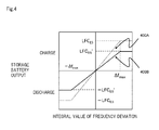
- FIG. 4 is a diagram showing an example of the charge and discharge gain line. Details of the charge and discharge gain line will be described later.
- Arithmetic operation section 204 is an example of processing means. Arithmetic operation section 204 generates allotment information (allotment coefficient K and maximum value ⁇ f max of the integral values of frequency deviations) based on the SOC of power storage device 3 received by communicator 201, and the charge and discharge gain line recognized by recognition section 203. Arithmetic operation section 204 transmits the allotment information (allotment coefficient K and maximum value ⁇ f max of the integral values of the frequency deviations) to respective local charge and discharge devices 100 from communicator 201.
- Power supply instruction section 300A is an example of an external control device.
- Power supply instruction section 300A includes frequency meter 301, communicator 302 and arithmetic operation section 303.
- Frequency meter 301 detects a system frequency of power system 1.
- Communicator 302 communicates with storage battery SCADA 200.
- communicator 302 receives total adjustable capacity P ES from storage battery SCADA 200.
- Arithmetic operation section 303 controls the operation of power supply instruction section 300A.
- arithmetic operation section 303 calculates area requirement (Area Requirement: AR) that is an output correction amount of a power station by using the system frequency detected by frequency meter 301.
- Arithmetic operation section 303 derives the LFC capacity by using area requirement AR, the LFC adjustment capacity of thermal power generation equipment 4 that is to be a control target, and total adjustable capacity P ES of the storage battery group that is to be a control target.
- Arithmetic operation section 303 acquires the LFC adjustment capacity of thermal power generation equipment 4 from a thermal power generation equipment control section not illustrated, and total adjustable capacity P ES is supplied to arithmetic operation section 303 from communicator 302.
- arithmetic operation section 303 allocates the LFC capacity to thermal power generation equipment 4 and the storage battery group in accordance with a ratio at which the LFC capacity is allocated to thermal power generation equipment 4 and the storage battery group.
- Arithmetic operation section 303 deals capacity LFC ES as LFC assignment capacity LFC ES , and generates a charge and discharge gain line (see Figure 4 ) that shows LFC assignment capacity LFC ES , and maximum value ⁇ f max of the integral values of the frequency deviations that are fixed in advance.
- Arithmetic operation section 303 transmits the charge and discharge gain line to storage battery SCADA 200 from communicator 302.
- P ES deriving operation an operation of storage battery SCADA 200 deriving total adjustable capacity P ES based on SOC of power storage device 3 (hereinafter, called a "P ES deriving operation") will be described.
- P ES deriving operation information of rated output P(n) and the like of the storage battery of each ID (the kWh of the battery, the usable SOC range, for example, the range of 30% to 90% and the like) is needed.
- the information thereof is basically stationary information, and therefore, in the present exemplary embodiment, storage battery SCADA 200 is assumed to acquire the information thereof from each of local charge and discharge devices 100 in advance.
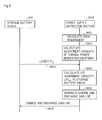
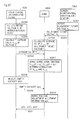
- Figure 5 is a sequence diagram for explaining the P ES deriving operation.
- the number of local charge and discharge devices 100 is set at one to simplify explanation.
- Communicator 201 of storage battery SCADA 200 transmits an information request that requests SOC from each of local charge and discharge devices 100 (step S501).
- arithmetic operation section 104 causes detector 101 to detect SOC of power storage device 3 when arithmetic operation section 104 receives the information request requesting SOC via communicator 102 (step S502).
- arithmetic operation section 104 transmits SOC detected by detector 101 together with ID, to storage battery SCADA 200 from communicator 102 (step S503).
- ID is assumed to be a consecutive number (n) from “1" to "N”.
- storage battery SCADA 200 When storage battery SCADA 200 receives SOC (hereinafter, called “SOC(n)”) that is assigned with ID from each of local charge and discharge devices 100, storage battery SCADA 200 derives total adjustable capacity P ES (step S504).
- SOC(n) SOC
- P ES total adjustable capacity
- Storage battery SCADA 200 and each of local charge and discharge devices 100 repeat the operation of steps S501 to S504, namely, the P ES deriving operation at periods T.
- Communicator 201 of storage battery SCADA 200 collects real-time SOC(n) from each of local charge and discharge devices 100.
- recognition section 203 of storage battery SCADA 200 derives storage battery distribution factor ⁇ discharge (n) at the time of discharge and storage battery distribution factor ⁇ charge (n) at the time of charge, for each of power storage devices 3, by using SOC(n) and storage battery distribution factor curves 202a and 202b (see Figures 3A and 3B ) that are retained in database 202.
- recognition section 203 derives P ES,discharge and P ES,charge by using storage battery distribution factor discharge (n) at the time of discharge, storage battery distribution factor ⁇ charge (n) at the time of charge, respective rated outputs P(n) of N of power storage devices 3 in total, and formulas shown in formula 1 and formula 2.
- recognition section 203 adopts a smaller value out of P ES,discharge and P ES,charge , as total adjustable capacity P ES . This is because in order to adjust the system frequency, charge and discharge in power storage device 3 is required with about the same frequency, and the total adjustable capacity with which both charge and discharge can be performed is needed. Note that the total adjustable capacity is the value with which charge and discharge are considered to be able to be continued at least during the time period of period T.
- Figure 6 is a sequence diagram for explaining the recognition operation.
- Arithmetic operation section 303 of power supply instruction section 300A calculates area requirement AR by using the system frequency detected by frequency meter 301 (step S601).
- arithmetic operation section 303 collects the LFC adjustment capacity of thermal power generation equipment 4 from a thermal power generation equipment controller not illustrated (step S602).
- communicator 201 of storage battery SCADA 200 transmits the newest total adjustable capacity P ES among calculated total adjustable capacities P ES to power supply instruction section 300A (step S603).
- Communicator 302 of power supply instruction section 300A receives the newest total adjustable capacity P ES transmitted from communicator 201 of storage battery SCADA 200, and outputs the newest total adjustable capacity P ES to arithmetic operation section 303.
- arithmetic operation section 303 determines a ratio of assignment of the LFC capacity to thermal power generation equipment 4 and assignment of the LFC capacity to the storage battery group (LFC assignment capacity LFC ES ), with an eye to economy while considering assignment amounts of EDC (Economic power supply control) component.
- arithmetic operation section 303 generates a charge and discharge gain line (see Figure 4 ) showing LFC assignment capacity LFC ES , and maximum value ⁇ f max of the integral values of the frequency deviations set in advance (step S605).
- the charge and discharge gain line shown in Figure 4 shows the charge and discharge amount of the storage battery group with respect to integral value ⁇ f of the frequency deviation.
- a charge and discharge gain line with use of a frequency deviation may be used, other than the charge and discharge gain line shown in Figure 4 . In this case, the operation becomes a governor free operation, rather than an LFC operation.
- the integral values of the frequency deviations that are used in the present exemplary embodiment for example, the integral value of the frequency deviation that is used in the allotment information and allotment power amount information, and arithmetic operation section 104, power supply instruction section 300A and local charge and discharge device 100 is replaced with a frequency deviation.
- arithmetic operation section 303 transmits the charge and discharge gain line to storage battery SCADA 200 from communicator 302 (step S606).
- recognition section 203 of storage battery SCADA 200 receives charge and discharge gain lines via communicator 201, and retains only the newest charge and discharge gain line among the charge and discharge gain lines.
- Figure 7 is a sequence diagram for describing the allotment operation.
- the number of local charge and discharge devices 100 is set at one in order to simplify explanation.
- Arithmetic operation section 204 of storage battery SCADA derives allotment coefficient K by using LFC assignment capacity LFC ES shown in the newest charge and discharge gain line retained by recognition section 203, the newest total adjustable capacity P ES which recognition section 203 has, and mathematical expression shown in formula 3 (step S701).
- K LFC ES P ES
- arithmetic operation section 204 transmits allotment information showing allotment coefficient K and maximum value ⁇ f max of the integral values of the frequency deviations shown in the newest charge and discharge gain line to each of local charge and discharge devices 100 from communicator 201 (step S702).
- formula 3 is used as allotment coefficient K in the present exemplary embodiment, but besides the above, a flexible operation can be performed such as an operation of instructing the individual storage batteries to forcibly issue outputs that is close to a limit as the value of allotment coefficient K or the like at the time of a desperate situation.
- step S702 the following processing is executed in step S702.
- Arithmetic operation section 204 determines a smaller value out of the newest storage battery distribution factor ⁇ discharge (n) at the time of discharge and storage battery distribution factor ⁇ charge (n) at the time of charge that are derived by recognition section 203 as storage battery distribution factor ⁇ (n), for each of power storage devices 3.
- arithmetic operation section 204 generates operation-related information showing storage battery distribution factor ⁇ (n) and rated output P(n) that is retained in database 202, for each of power storage devices 3.
- arithmetic operation section 204 adds allotment information to each operation-related information, and transmits the allotment information to which the operation-related information is added from communicator 201 to local charge and discharge device 100 corresponding to power storage device 3 corresponding to the operation-related information.
- arithmetic operation section 104 receives the allotment information with the operation-related information via communicator 102.
- Arithmetic operation section 104 derives local charge and discharge gain coefficient G(n) by using the allotment information with the operation-related information and the mathematical expression shown in formula 4 (step S703).
- G n K ⁇ ⁇ n ⁇ P n ⁇ ⁇ f max
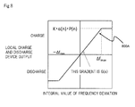
- arithmetic operation section 104 derives local charge and discharge gain line 800A shown in Figure 8 by using local charge and discharge gain coefficient G(n), and maximum value ⁇ f max of the integral values of the frequency deviations shown in the allotment information with the operation-related information (step S704).
- Local charge and discharge gain line 800A shown in Figure 8 becomes a straight line that passes through origin 0, and has a gradient that is local charge and discharge gain coefficient G(n) when integral value ⁇ f of the frequency deviation is in a range of- ⁇ f max ⁇ ⁇ f ⁇ ⁇ f max , takes a constant value of "-K ⁇ (n) ⁇ P(n)" (the minus sign represents discharge) when integral value ⁇ f of the frequency deviation is in a range of ⁇ f ⁇ - ⁇ f max , and takes a constant value of "K ⁇ (n) ⁇ P(n)" when integral value ⁇ f of the frequency deviation is in a range of ⁇ f max ⁇ ⁇ f.
- arithmetic operation section 104 receives pieces of allotment information together with the operation-related information via communicator 102, and retains only the newest piece of allotment information with the operation-related information from among the pieces of allotment information together with the operation-related information.
- charge and discharge control operation the operation of local charge and discharge device 100 controlling charge and discharge of power storage device 3 based on the allotment information with the operation-related information and the system frequency (hereinafter, called a “charge and discharge control operation") will be described.
- Figure 9 is a sequence diagram for describing the charge and discharge control operation.
- arithmetic operation section 104 causes frequency meter 103 to detect a system frequency (step S901).
- arithmetic operation section 104 calculates integral value ⁇ f of the frequency deviation by subtracting the reference frequency of the system frequency from the detection result of the frequency meter 103 and integrating the subtracted result (step S902).
- arithmetic operation section 104 calculates a charge amount or a discharge amount of power storage device 3 in accordance with integral value ⁇ f of the frequency deviation and the local charge and discharge gain line (step S903).
- arithmetic operation section 104 calculates an absolute value of a value (G(n) ⁇ f) that is obtained by multiplying local charge and discharge gain coefficient G(n) by integral value ⁇ f of the frequency deviation as an adjustment power amount.
- arithmetic operation section 104 calculates a value (K ⁇ (n) ⁇ P(n)) obtained by multiplying allotment coefficient K, storage battery distribution factor ⁇ (n) and rated output P(n) by one another as the adjustment power amount.
- K ⁇ (n) ⁇ P(n) a value obtained by multiplying allotment coefficient K, storage battery distribution factor ⁇ (n) and rated output P(n) by one another as the adjustment power amount.
- arithmetic operation section 104 causes power storage device 3 to execute a charge operation by an adjustment power amount, and causes power storage device 3 to execute a discharge operation by an adjustment power amount when integral value ⁇ f of the frequency deviation is a negative value (step S904).
- the LFC capacity takes values in both a charge direction and a discharge direction, and therefore, it is not desirable that SOC of power storage device (battery) 3 be deviated to zero or one. If a deviation occurs, power that can be charged or discharged becomes small, and total adjustable capacity P ES becomes small, as also shown in the examples of the storage battery distribution factor curves shown in Figures 3A and 3B .
- local charge and discharge device 100 may control charge and discharge of power storage device 3 by adding a charge and discharge amount for correcting SOC (SOC correction offset), in addition to the charge and discharge amount that is calculated from the information showing the demand and supply state of the entire power system 1 measured at short periods (measurement value of the system frequency in the present exemplary embodiment) and the allotment information that is distributed from storage battery SCADA 200 at long periods.
- SOC correction offset a charge and discharge amount for correcting SOC
- arithmetic operation section 104 accepts information necessary to determine the SOC correction offset value (SOC correction offset-related information) from storage battery SCADA 200 via communicator 102, and arithmetic operation section 104 determines the SOC correction offset value in accordance with the SOC correction offset-related information.
- storage battery SCADA 200 may transmit the SOC correction offset-related information simultaneously with transmitting the allotment information.
- the SOC correction offset-related information is an example of correction information.
- the SOC correction offset-related information showing the SOC correction offset value itself is cited, and storage battery SCADA 200 distributes the SOC correction offset-related information to each of local charge and discharge devices 100.
- arithmetic operation section 204 of storage battery SCADA 200 refers to SOC received from each of local charge and discharge devices 100, and distributes the SOC correction offset-related information showing the SOC correction offset value for charge to power storage device 3 in which SOC is deviated to zero out of power storage devices 3, and distributes the SOC correction offset-related information showing the SOC correction offset value for discharge to power storage device 3 in which SOC is deviated to one out of power storage devices 3.
- power storage device 3 in which the SOC is deviated to zero is a power storage device in which the value of SOC is a first threshold value which is larger than zero and smaller than 0.5, or smaller, for example.
- power storage device 30 in which SOC is deviated to one is a power storage device in which the value of SOC is a second threshold value that is larger than 0.5 and smaller than one, or larger, for example.
- Arithmetic operation section 104 of local charge and discharge device 100 calculates a correction power amount by adding the SOC correction offset value to the adjustment power amount when integral value ⁇ f of the frequency deviation is a positive value.
- arithmetic operation section 104 of local charge and discharge device 100 calculates the correction power amount by adding the SOC correction offset value to the multiplication result of multiplying the adjustment power amount by -1 when integral value ⁇ f of the frequency deviation is a negative value.
- arithmetic operation section 104 When the correction power amount is a positive value, arithmetic operation section 104 causes power storage device 3 to execute a charge operation by the correction power amount, and when the correction power amount is a negative value, arithmetic operation section 104 causes power storage device 3 to execute a discharge operation by the correction power amount. When the correction power amount is zero, arithmetic operation section 104 does not execute charge and discharge of power storage device 3.
- arithmetic operation section 204 may determine each SOC correction offset-related information so that the total sum of the SOC correction offset values of all power storage devices 3 at the same time point (hereinafter, called an "offset total sum") becomes zero. In this case, the SOC correction offset does not influence capacity LFC ES .
- arithmetic operation section 204 may determine each SOC correction offset-related information so that the speed of change of the offset total sum (speed of change of the offset total sum with a lapse of time) becomes a speed threshold value or less (the speed threshold value is, for example, total adjustable capacity P ES /30 minutes.), instead of always making the offset total sum zero.
- the speed threshold value the upper limit of the response speed of a power stabilizing operation (an LFC operation) performed by an external power stabilizing device (for example, thermal power generation equipment 4) connected to power system 1 is used.
- a slow change of power demand and supply at a period longer than 30 minutes, for example, is allotted as a change of power demand and supply that is absorbed by the power stabilizing operation of thermal power generation equipment 4 by EDC. Therefore, a change of power demand and supply due to a change in the offset total sum is highly likely to be absorbed by the external power stabilizing device. Accordingly, the change of power demand and supply due to the SOC correction offset value does not influence a relatively high-speed change of demand and supply accompanying charge and discharge of power storage device 3.
- arithmetic operation section 104 refers to SOC via detector 101, and when SOC becomes a target value (for example, reference SOC that is 0.5), arithmetic operation section 104 may autonomously invalidate an SOC correction offset and control charge and discharge of power storage device 3.
- a target value for example, reference SOC that is 0.5
- arithmetic operation section 104 does not have to execute the processing of calculating the SOC correction offset value, and an increase in the processing load of arithmetic operation section 104 can be reduced.
- SOC correction offset-related information there is a method in which storage battery SCADA 200 distributes parameters that are needed when each of local charge and discharge devices 100 determines the SOC correction offset value to each of local charge and discharge devices 100.
- the n th local charge and discharge device 100 determines SOC correction offset value P offset,n (t) by using the following formula 5.
- P offset , n t SOC target , n - SOCn t / Tn
- SOC target,n is an SOC value (a reference state of power storage device 3)
- SOCn (t) is an SOC value of power storage device 3 of n th local charge and discharge device 100 at a time point t
- Tn is a time constant (speed-related information).
- Arithmetic operation section 104 of local charge and discharge device 100 acquires the SOC value of power storage device 3 via detector 101, acquires SOC target,n and Tn from storage battery SCADA 200 via communicator 102, and calculates SOC correction offset value P offset,n (t) from formula 5.
- SOC correction offset value P offset,n (t) can be changed in accordance with an actual change of SOC. Furthermore, for example, when a communication trouble occurs and SOC target,n and Tn are not newly received, SOC correction offset value P offset,n (t) can continue to be calculated by using SOC target,n and Tn that are already received.
- arithmetic operation section 204 of storage battery SCADA 200 determines SOC target,n of each of power storage devices
- SOC target,n 0.5
- Tn represents the speed at which SOC is corrected
- arithmetic operation section 204 sets Tn so that change of the total sum of the values of the SOC correction offsets of respective power storage devices 3 becomes a change at a period longer than 30 minutes, in order that the change of power demand and supply due to the SOC correction offset value is absorbed by EDC.
- each of arithmetic operation sections 104 may calculate SOC correction offset value P offset,n (t) by using registered SOC target,n and Tn.
- arithmetic operation section 104 of local charge and discharge device 100 calculates the correction power amount by adding the SOC correction offset value to the adjustment power amount when integral value ⁇ f of the frequency deviation is a positive value, and when integral value ⁇ f of the frequency deviation is a negative value, arithmetic operation section 104 calculates the correction power amount by adding the SOC correction offset value to a multiplication result of multiplying the adjustment power amount by -1.
- arithmetic operation section 104 When the correction power amount is a positive value, arithmetic operation section 104 causes power storage device 3 to execute a charge operation by the correction power amount. When the correction power amount is a negative value, arithmetic operation section 104 causes power storage device 3 to execute a discharge operation by the correction power amount. When the correction power amount is zero, arithmetic operation section 104 does not execute charge and discharge of power storage device 3.
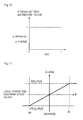
- the storage battery distribution factor curve the storage battery distribution factor is kept at one irrespective of the value of SOC as shown in Figure 10 .
- arithmetic operation section 204 of storage battery SCADA 200 determines a local charge and discharge gain line (hereinafter called a "reference local charge and discharge gain line”) of each of local charge and discharge devices 100 at the time when a local charge and discharge gain line of each of local charge and discharge devices 100 at a time of distribution coefficient K being one, namely, at a time of distribution coefficient K being not taken into consideration.
- a local charge and discharge gain line hereinafter called a "reference local charge and discharge gain line"
- Figure 11 is a diagram showing the reference local charge and discharge gain line before the SOC correction offset is applied to each of power storage devices 3.
- the axis of ordinates represents the local charge and discharge device output that is the charge and discharge amount of each of power storage devices 3
- axis of abscissa represents value X showing a state of a total demand and supply balance of power system 1. While integral value ⁇ f of the frequency deviation is used in the present exemplary embodiment as an example of X, a frequency deviation (Hz), a total demand and supply adjustment amount (W) and the like are cited, besides integral value ⁇ f of the frequency deviation.
- the local charge and discharge device output is proportional to X with a gradient of local charge and discharge gain coefficient G(n) in a region in which X is from -Xr to Xr inclusive. Furthermore, since power storage device 3 cannot issue output of rated output P(n) or more, in a region other than the region in which X is from -Xr to Xr inclusive, the local charge and discharge device output is the rated output.
- a value of Xr is the value of X at the time of the local charge and discharge device output being rated output P(n). Note that here, the rated output of charge and the rated output of discharge are set as the same values as the positive and negative signs being inverted, but the case does not have to be always the same.
- Arithmetic operation section 204 of storage battery SCADA 200 calculates an SOC correction offset amount of each of power storage devices 3 after acquiring the value of SOC of each of power storage devices 3. Note that a method for calculating the SOC correction offset amount will be described later. Arithmetic operation section 204 corrects the reference local charge and discharge gain line so that the total sum of the charge and discharge amounts of respective power storage devices 3 to which the SOC correction offset amounts are further added is in a target function shape in the region of-Xr ⁇ X ⁇ Xr (for example, the total sum of the charge and discharge amounts becomes linear with respect to X in the region of-Xr ⁇ X ⁇ Xr). Subsequently, arithmetic operation section 204 transmits the corrected reference local charge and discharge gain line to respective local charge and discharge devices 100.
- Figure 12 is a diagram showing an example of the corrected reference local charge and discharge gain line.
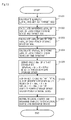
- arithmetic operation section 204 calculates target SOC by using collected SOC of each of power storage device 3 (step S1301).
- target SOC ⁇ n WH n (t)/ ⁇ n WHr n .
- WH n (t) and WHr n represent a charge power amount (Wh) at a time point t of power storage device 3n, and a maximum charge power amount (Wh) that is the rated output.
- ⁇ n means formula 6.
- arithmetic operation section 204 obtains a difference ⁇ SOC n of the SOC value and target SOC of each of power storage devices 3 (step S1302).
- arithmetic operation section 204 divides ⁇ WHn by time constant T (for example, five minutes) set in advance and calculates offset ⁇ Poffset n (W) for each of power storage devices 3 (step S1304).
- Time constant T is changeable without being limited to five minutes.
- arithmetic operation section 204 sets T so that the change of the total sum of offsets ⁇ Poffset n of respective power storage devices 3 occurs a change at a period longer than 30 minutes.
- Arithmetic operation section 204 firstly adds the value (offset ⁇ Poffset n ) to the reference local charge and discharge gain line shown in Figure 11 .
- arithmetic operation section 204 adds additional correction to the reference local charge and discharge gain line to which offset ⁇ Poffset n is added, in steps S1305 and S1306, so that even if each of power storage devices 3 performs charge and discharge by adding offset ⁇ Poffset n , the total sum of the charge and discharge amounts of all power storage devices 3 at the same time point becomes linear with respect to X in the region of - Xr ⁇ X ⁇ Xr.
- step S1305 arithmetic operation section 204 obtains value Xlim n of X with which the reference local charge and discharge gain line after ⁇ Poffset n is added thereto has a rated output within a range of
- ⁇ Xr a range of
- arithmetic operation section 204 adds an offset to the gradient of the reference local charge and discharge gain line of another power storage device, and brings the total sum of the charge and discharge amounts of respective power storage devices 3 into a linear relation with respect to X in the region of - Xr ⁇ X ⁇ Xr, in step S1306.
- the total charge and discharge amount of respective power storage devices 3 is in a linear relation with respect to X in the region of - Xr ⁇ X ⁇ Xr, and therefore, bringing the total charge and discharge amount of respective power storage devices 3 into a linear relation with respect to X in the region of - Xr ⁇ X ⁇ Xr means bringing the total sum of the offsets of respective power storage devices 3 into a linear relation with respect to X in the region of - Xr ⁇ X ⁇ Xr.
- arithmetic operation section 204 brings the total charge and discharge amount of respective power storage devices 3 (power storage devices 31 and 32) into a linear relation with respect to X in the region of Xlim 1 ⁇ X ⁇ Xr by adding an offset to the gradient of the reference local charge and discharge gain line of power storage device 32, in the region of Xlim 1 ⁇ X ⁇ Xr. Further in the example shown in Figure 12 , the output of power storage device 32 is saturated to the rated output in a region of -Xr ⁇ X ⁇ Xlim 2 .
- arithmetic operation section 204 brings the total charge and discharge amount of respective power storage devices 3 (power storage devices 31 and 32) into a linear relation with respect to X in the region of - Xr ⁇ X ⁇ Xlim 2 by adding an offset to the gradient of the reference local charge and discharge gain line of power storage device 31, in the region of - Xr ⁇ X ⁇ Xlim 2 .
- arithmetic operation section 204 transmits the corrected reference charge and discharge gain lines to respective local charge and discharge devices 100 (step S1307). Note that the transmission timing may be synchronized with the timing of transmitting the allotment information.
- the corrected reference local charge and discharge gain lines are examples of the operation information, and each shows a relation of a value obtained by adding the offset value and the local charge and discharge device output at the time when the offset is not added (information showing the operation content of the power storage device) and X.
- arithmetic operation section 104 determines the power amount and an operation (a charge operation or a discharge operation) of power storage device 3 corresponding to integral value ⁇ f of the frequency deviation by using the corrected reference local charge and discharge gain line, and causes power storage device 3 to execute the determined operation by the power amount of the multiplication result of multiplying the power amount corresponding to integral value ⁇ f of the frequency deviation by allotment coefficient K.
- the total charge and discharge amount of all power storage devices 3 can be brought into a linear relation with respect to X in the region of-Xr ⁇ X ⁇ Xr similarly to the case where the SOC correction operation is not executed. Consequently, the total charge and discharge amount of power storage device 3 can be controlled with high precision based on X.
- Figure 14 is a diagram for explaining a way of giving an offset that is different from the aforementioned example.
- an offset is given to G(n).
- arithmetic operation section 204 makes G(n) on the charge side small and makes G(n) on the discharge side large in the reference local charge and discharge gain line, and when SOC of power storage device 3 is lower than target SOC, arithmetic operation section 204 makes G(n) on the charge side large and makes G(n) on the discharge side small.
- the output of power storage device 31 is saturated to the rated output in the region of Xlim 1 ⁇ X ⁇ Xr. Therefore, arithmetic operation section 204 brings the total charge and discharge amount of respective power storage devices 3 (power storage devices 31 and 32) into a linear relation with respect to X in the region of Xlim 1 ⁇ X ⁇ Xr by adding an offset to the gradient of the reference local charge and discharge gain line of power storage device 32. Furthermore, in the example shown in Figure 14 , the output of power storage device 32 is saturated to the rated output in a region of - Xr ⁇ X ⁇ Xlim 2 .
- arithmetic operation section 204 brings the total charge and discharge amount of respective power storage devices 3 (power storage devices 31 and 32) into a linear relation with respect to X in the region of - Xr ⁇ X ⁇ Xlim 2 by adding an offset to the gradient of the reference local charge and discharge gain line of power storage device 31.
- control allotment with consideration given to economic efficiency and response speed of the thermal power generation equipment can be given to the distributed storage battery group.
- arithmetic operation section 104 controls the operation of power storage device 3 based on the allotment information provided by storage battery SCADA 200 and the system frequency. Therefore, the operation of power storage device 3 can be adjusted in response to not only the allotment information but also an actual change in the state of the power system.
- the above-described effect is also brought about with local charge and discharge device 100 including detector 101, communicator 102 and arithmetic operation section 104. Furthermore, the above-described effect is also brought about with storage battery SCADA 200 including communicator 201, recognition section 203 and arithmetic operation section 204. Furthermore, the above-described effect is also brought about with the battery control system including local charge and discharge device 100 including detector 101, communicator 102 and arithmetic operation section 104, and storage battery SCADA 200 including communicator 201, recognition section 203 and arithmetic operation section 204.
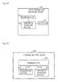
- Figure 15 is a diagram showing the local charge and discharge device including detector 101, communicator 102 and arithmetic operation section 104.
- Figure 16 is a diagram showing storage battery SCADA 200 including communicator 201, recognition section 203 and arithmetic operation section 204.
- storage battery SCADA 200 accepts the charge and discharge gain line that is used to generate allotment information from power supply instruction section 300A that controls power system 1. Therefore, it is possible to acquire the charge and discharge gain line with consideration given to the operation of thermal power generation equipment 4 on the system side, for example. Therefore, power demand and supply balance control by the thermal power generation equipment 4 on the system side and power storage device 3 can be carried out with high precision.
- storage battery SCADA 200 accepts the charge and discharge gain line in which total adjustable capacity P ES is reflected from power supply instruction section 300A. Therefore, the load of power storage device 3 can be adjusted in accordance with the total adjustable capacity of power storage device 3.
- local charge and discharge device 100 controls the operation of power storage device 3 based on integral value ⁇ f of the frequency deviation and the allotment information (the allotment coefficient K and maximum value ⁇ f max of the integral values of the frequency deviations). Therefore, the operation of power storage device 3 can be adjusted in response to not only the allotment information but also the actual change of the system frequency.
- the time interval at which local charge and discharge device 100 acquires allotment information from storage battery SCADA 200 is longer than the operation interval at which local charge and discharge device 100 controls the operation of power storage device 3 by using the allotment information. Therefore, as compared with the case in which the time interval at which allotment information is acquired is the operation time interval of power storage device 3 or less, the processing of acquiring the allotment information becomes less susceptible to a communication problem that is likely to occur between local charge and discharge device 100 and storage battery SCADA 200.
- arithmetic operation section 104 controls the operation of power storage device 3 based on SOC and the SOC correction offset value of power storage device 3. Therefore, SOC of power storage device 3 can be prevented from being deviated to zero or one, and total adjustable capacity P ES can be prevented from being small as a result of power that can be charged or discharged with use of power storage device 3 becoming small.
- arithmetic operation section 104 determines the correction power amount that is the result of adjusting the power amount for stabilizing the power of power system 1 which is determined in accordance with integral value ⁇ f of the frequency deviation based on allotment coefficient K and SOC, and executes charge or discharge with the correction power amount for power storage device 3. Therefore, while SOC of power storage device 3 is prevented from being deviated to zero or one, the operation of power storage device 3 can be adjusted in accordance with not only the allotment information but also an actual change of the state of the power system.
- arithmetic operation section 204 may generate SOC correction offset-related information showing the charge amount or the discharge amount that brings SOC of power storage device 3 close to reference SOC based on SOC of power storage device 3, and arithmetic operation section 104 may control power storage device 3 by using the charge amount or the discharge amount shown in the SOC correction offset-related information. In this case, arithmetic operation section 104 does not have to execute processing to calculate the SOC correction offset value, and the load of arithmetic operation section 104 can be reduced.
- arithmetic operation section 204 may generate each SOC correction offset-related information so that the total sum of the SOC correction offset value for charge and the SOC correction offset value for discharge becomes zero. In this case, the SOC correction offset can be prevented from influencing capacity LFC ES .
- arithmetic operation section 204 may generate each SOC correction offset-related information so that the speed of change of the offset total sum with the lapse of time becomes the upper limit of the response time of the power stabilizing operation that is performed by thermal power generation equipment 4 or lower.
- change of power demand and supply due to change in the offset total sum is highly likely to be absorbed by the power stabilizing operation of thermal power generation equipment 4. Therefore, the change in power demand and supply due to the SOC correction offset value is highly unlikely to influence a relatively high-speed change in demand and supply that accompanies charge and discharge of power storage device 3.
- arithmetic operation section 204 may determine the charge amount or the discharge amount that brings the SOC close to target SOC, for each of power storage devices 3, and may correct the charge amount or the discharge amount so that the total sum of the charge amounts or the discharge amounts of respective power storage devices 3 is in a linear relation with respect to integral value ⁇ f of the frequency deviation in the situation in which integral value ⁇ f of the frequency deviation is within a predetermined range. Furthermore, arithmetic operation section 204 may generate the corrected reference local charge and discharge gain line by using the charge amount or the discharge amount after correction. Subsequently, arithmetic operation section 104 may control the operation of power storage device 3 based on the corrected reference local charge and discharge gain line. In this case, the total charge and discharge amount of power storage device 3 can be controlled with high precision based on X.
- arithmetic operation section 104 may generate the SOC correction offset value based on the difference between SOC target,n received from storage battery SCADA 200 and SOC of power storage device 3.
- the SOC correction offset value can be properly changed in response to the actual change of SOC of power storage device 3.
- the SOC correction offset value can continue to be calculated with use of SOC target,n that has already been received.
- arithmetic operation section 104 may generate the value of the SOC correction offset that indicates the charge amount or the discharge amount that brings SOC of power storage device 3 close to SOC target,n by correcting the difference between SOC target,n and SOC of power storage device 3 with Tn received from storage battery SCADA 200.
- the speed of change of the offset total sum can be adjusted with Tn. Therefore, the change in power demand and supply due to the change in the offset total sum can be absorbed by the power stabilizing operation of thermal power generation equipment 4.
- the maximum value of the output amount of power storage device 3 that is assigned to control of reactive power P may be used instead of rated output P(n).
- storage battery SCADA 200, local control device 100 and the like properly collect and distribute time synchronization information in the process of information communication, and time synchronization is performed among the devices.
- local charge and discharge device 100 may be realized by a computer.
- the computer reads and executes the program recorded in a recording medium such as computer-readable CD-ROM (Compact Disk Read Only Memory), and executes the respective functions that local charge and discharge device 100 has.
- a recording medium such as computer-readable CD-ROM (Compact Disk Read Only Memory), and executes the respective functions that local charge and discharge device 100 has.
- the recording medium is not limited to a CD-ROM and other recording media can be used.
- storage battery SCADA 200 may be realized by a computer.
- the computer reads and executes the program recorded in a computer-readable recording medium, and executes each of the functions that storage battery SCADA 200 has.
- EMS Electronicgy Management System
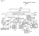
- Figure 17 is a diagram showing power control system 1000A that adopts a battery control system of a second exemplary embodiment of the present invention.
- the components that have the same configurations as shown in Figure 1 or 2 are assigned the same reference signs.
- power control system 1000A includes power system 1A, photovoltaic power generator (solar battery) 2, power storage devices (storage batteries) 3(1) to 3(n), load 7, local charge and discharge devices 100A(1) to 100A(n), ESMS (Energy Storage Management System) 200A, sensor-incorporating switch slave station 700A, SVR slave station 700B, and LRT (Load Ratio Transformer) slave station 700C.
- Local charge and discharge devices 100A(1) to 100A(n) are in one-to-one correspondence with power storage devices (storage batteries) 3(1) to 3(n). Note that Figure 17 shows local charge and discharge device 100A(i) from among local charge and discharge devices 100A(1) to 100A(n) in order to simplify the explanation.
- Each of local charge and discharge devices 100A, ESMS 200A, sensor-incorporating switch slave station 700A, SVR slave station 700B and LRT slave station 700C are connected to communication network 800.
- Power system 1A includes distribution substation LRT 1A1, breakers 1A2, switch 1A3, sensor-incorporating switch 1A4, SVR 1A5 and pole transformer 1A6.
- Power control system 1000A limits variation in system frequency that result from changes in the amount of power generated by photovoltaic power generator 2, due to weather conditions, which is of concern to power system 1A, to which photovoltaic power generator 2 is interconnected, by a voltage adjusting operation of SVR 1A5 and charge and discharge operations of respective power storage devices 3.
- Power system 1A is a system for supplying power to load 7 on the customer side. While power system 1A also includes other devices (for example, thermal power generation equipment), these devices are omitted to simplify the explanation.
- LRT 1A1, SVR 1A5 and pole transformer 1A6 are voltage adjustors.
- Breaker 1A2, switch 1 A3 and sensor-incorporating switch 1A4 are used to disconnect a specific part of power system 1A (for example, a part where a trouble occurs) from power system 1A.
- Each local charge and discharge device 100A is an example of a first control device or a battery control device. Each local charge and discharge device 100A also bears the function of a slave station provided in corresponding power storage device 3. Note that the number of local charge and discharge devices 100A and the number of power storage devices 3 are each one or more.
- Figure 18 is a diagram showing an example of local charge and discharge device 100A(i).
- local charge and discharge device 100A(i) includes voltage detector 101A1, empty capacity detector 101A2, communicator 101A3, and arithmetic operation section 101A4.
- Empty capacity detector 101A2 detects empty capacity Q i of power storage device 3(i) at periods Tg.
- empty capacity Q i of power storage device 3(i) refers to capacity that can be used by power storage device 3(i) to adjust the voltage of power system 1 A at the point of time, is calculated based on SOC, for example, and is ensured for the time period T g .
- Communicator 101A3 is an example of first communication means. Communicator 101A3 communicates with ESMS 200A.
- Arithmetic operation section 101A4 executes a control information acquiring operation of obtaining operation control information to control the operation of power storage device 3(i) from ESMS 200A (transmission and reception processing), and a charge and discharge control operation to control a charge and discharge operation of power storage device 3(i) based on the operation control information and voltage V i at interconnection point i (battery operation control processing).
- Arithmetic operation section 101A4 intermittently executes the control information acquiring operation, and executes the charge and discharge control operation at time intervals shorter than the time intervals of the control information acquiring operation.
- period T g and Period T h are not limited to 10 minutes and 0.1 seconds, and period T g can be longer than period T h .
- both or any one of the operation time intervals of the control information acquiring operation and the operation time interval of the charge and discharge control operation do not or does not have to be constant, and the shortest time interval from among the respective operation time intervals of the control information acquiring operation can be longer than the longest time from among the respective operation time intervals of the charge and discharge control operation.
- arithmetic operation section 101A4 may execute the control information acquiring operation in response to the voltage request that requests voltage V i of interconnection point i sent from ESMS 200A, or may execute the control information acquiring operation autonomously.
- Arithmetic operation section 101A4 transmits voltage V i of interconnection point i detected by voltage detector 101A1, and empty capacity Q i of power storage device 3(i) detected by empty capacity detector 101A2 to ESMS 200A from communicator 101A3.
- Communicator 101A3 transmits voltage V i of interconnection point i and empty capacity Q i of power storage device 3(i) to ESMS 200A, and thereafter, receives operation control information from ESMS 200A.
- Arithmetic operation section 101A4 controls the charge and discharge operation of power storage device 3(i) based on the operation control information received by communicator 101A3, and voltage V i of interconnection point i detected by voltage detector 101A1.
- Figure 19 is a diagram showing an example of sensor-incorporating switch slave station 700A.
- Sensor-incorporating switch slave station 700A is an example of an external control device.
- Sensor-incorporating switch slave station 700A includes voltage detector 700A1, communicator 700A2 and arithmetic operation section 700A3.
- Voltage detector 700A1 detects adjustment target voltage V T that is a voltage of voltage adjustment target spot T (see Figure 17 ) in power system 1A.
- Communicator 700A2 communicates with ESMS 200A.
- Arithmetic operation section 700A3 transmits adjustment target voltage V T detected by voltage detector 700A1 to ESMS 200A from communicator 700A2 at periods T g .
- SVR slave station 700B communicates with ESMS 200A. For example, SVR slave station 700B notifies ESMS 200A of an output voltage of SVR 1A5 at periods Tg, and further, receives an SVR settling constant from ESMS 200A at periods Tg.
- the SVR settling constant is information for determining the output range of the output voltage of SVR 1A5 (hereinafter, called the "conversion output range") at the time of adjustment-target voltage V T falling within a proper voltage range.
- the SVR settling constant center value Vref(t) of the conversion output range, upper limit value Vref_high(t) of the conversion output range, and lower limit value Vref_low(t) of the conversion output range are used. Note that Vref(t) that expresses the center value of the conversion output range may be omitted.
- SVR slave station 700B sets the newest SVR settling constant to SVR 1A5.
- SVR 1A5 is an example of the voltage adjustment device.
- SVR 1A5 switches a tap (not illustrated) of SVR 1A5 and changes adjustment target voltage V T to be within a proper voltage range, when adjustment target voltage V T is continuously outside the proper voltage range for settling time period Ts, namely, when the output voltage of SVR 1A5 is continuously outside the conversion output range for the settling time period Ts.
- the control method of SVR 1A5 described above is a known technique.
- settling time period Ts is an example of a specific time period.
- Figure 20 is a diagram showing an example of ESMS 200A.
- ESMS 200A is an example of a second control device or a battery control support device.
- ESMS 200A includes communicator 200A1, recognition section 200A2 and arithmetic operation section 200A3.
- Communicator 200A1 is an example of second communication means. Communicator 200A1 communicates with respective local charge and discharge devices 100A and sensor-incorporating switch slave station 700A. For example, communicator 200A1 receives voltages V of respective interconnection points and empty capacities Q of corresponding power storage devices 3 from respective local charge and discharge devices 100A. Furthermore, communicator 200A1 receives adjustment target voltage V T from sensor-incorporating switch slave station 700A.
- Recognition section 200A2 is an example of recognition means. Recognition section 200A2 recognizes (stores) the information (voltages V of the respective interconnection points, empty capacities Q of respective power storage devices 3 and adjustment target voltage V T ) received by communicator 200A1 by associating the information with reception time points. Note that adjustment target voltage V T is an example of the situation of power system 1A.
- Arithmetic operation section 200A3 is an example of processing means. Arithmetic operation section 200A3 generates correlation information showing the correlation of voltage V of the interconnection point and adjustment target voltage V T for each of the interconnection points based on voltage V of each of the interconnection points received by communicator 200A1, and adjustment target voltage V T recognized by recognition section 200A2.
- arithmetic operation section 200A3 derives voltage adjustment allotment information ⁇ based on the newest empty capacity Q of each of power storage devices 3. For example, when arithmetic operation section 200A3 is notified of respective empty capacities Q of a plurality of power storage devices 3, arithmetic operation section 200A3 derives voltage adjustment allotment information ⁇ that makes the ratio of allotments higher for larger empty capacities Q among the empty capacities Q whose arithmetic operation section 200A3 is notified, for each of power storage devices 3.
- Arithmetic operation section 200A3 generates the operation control information including the correlation information and voltage adjustment allotment information ⁇ , for each of power storage devices 3, and transmits each piece of the operation control information to local charge and discharge device 100A corresponding to power storage device 3 that corresponds to the operation control information, from communicator 200A1.
- arithmetic operation section 200A3 generates SVR settling constants (Vref(t), Vref_high(t) and Vref_low(t)) based on adjustment target voltage V T , and the output voltage of SVR 1A5 whose arithmetic operation section 200A3 is notified from SVR slave station 700B. Note that a method for generating the SVR settling constants is a known technique, and therefore, a detailed explanation will be dropped. Arithmetic operation section 200A3 transmits the SVR settling constants (Vref(t), Vref_high(t) and Vref_low(t)) to SVR slave station 700B from communicator 200A1.
- Figure 21 is a sequence diagram for describing the setting operation.
- arithmetic operation section 700A3 causes voltage detector 700A1 to detect adjustment target voltage V T (step S2101), and transmits adjustment target voltage V T detected by voltage detector 700A1 to ESMS 200A from communicator 700A2 (step S2102).
- SVR slave station 700B detects the output voltage of SVR 1A5, and transmits the output voltage of SVR 1A5 to ESMS 200A (step S2103).
- recognition section 200A2 stores adjustment target voltage V T received by communicator 200A1 and the output voltage of SVR 1A5 by associating adjustment target voltage V T and the output voltage with each other.
- arithmetic operation section 200A3 derives the SVR settling constants (Vref(t), Vref_high(t) and Vref_low(t)) based on adjustment target voltage V T and the output voltage of SVR 1A5 in recognition section 200A2 (step S2104).
- arithmetic operation section 200A3 transmits the SVR settling constants to SVR slave station 700B from communicator 200A1 (step S2105).
- SVR slave station 700B When SVR slave station 700B receives SVR settling constants, SVR slave station 700B sets the SVR settling constants to SVR 1A5 (step S2106). Note that when SVR settling constants are already set to SVR 1A5, SVR slave station 700B updates the SVR settling constants set to SVR 1A5 to the newest SVR settling constants.
- Sensor-incorporating switch slave station 700A, SVR slave station 700B and ESMS 200A repeat steps S2101 to S2106 at periods Tg.
- SVR 1A5 switches the tap of SVR 1A5 to lower the output voltage of SVR 1A5, and changes the output voltage of SVR 1A5 to a voltage within the conversion output range.
- SVR 1A5 switches the tap of SVR 1A5 to raise the output voltage of SVR 1A5, and changes the output voltage of SVR 1A5 to a voltage within the conversion output range.
- settling time period Ts may be the value set in advance or may be changed with the lapse of time with consideration given to extending the life of SVR 1A5 and a secular change of SVR 1A5.
- the voltage of power system 1A is adjusted by the operation of SVR 1A5, high-speed variation components from among the variation components of the system voltage, for example, the components that result from output of a renewable power supply the power generation amount of which changes irregularly in accordance with the weather, cannot be handled with only the voltage adjustment by SVR 1A5.
- the voltage variation components that cannot be handled with the voltage adjustment by SVR 1A5 are reduced by the charge and discharge operations of respective power storage devices 3.
- ESMS 200A that generates operation control information that is required to perform the charge and discharge operations of power storage devices 3, and that transmits the operation control information to respective local charge and discharge devices 100A (hereinafter, called a "generation operation") will be described.
- Figure 22 is a sequence diagram for describing the generation operation.
- arithmetic operation section 700A3 causes voltage detector 700A1 to detect adjustment target voltage V T (step S2201), and transmits adjustment target voltage V T detected by voltage detector 700A1 to ESMS 200A from communicator 700A2 (step S2202).
- recognition section 200A2 stores adjustment target voltage V T received by communicator 200A1.
- arithmetic operation section 200A3 of ESMS 200A calculates average value V T,AVE of adjustment target voltage V T in recognition section 200A2 (step S2203).
- Recognition section 200A2 retains average value V T,AVE that is the calculation result.
- arithmetic operation section 101A4 causes voltage detector 101A1 to detect voltage V of the interconnection point, and retains voltage V (step S2204).
- voltage V i of interconnection point i will be cited as an example and described in order to simplify the explanation.
- arithmetic operation section 101A4 calculates average value V i,AVE of retained voltages V i (step S2205).
- arithmetic operation section 101A4 transmits average value V i,AVE to ESMS 200A from communicator 101A3 (step S2206).
- recognition section 200A2 stores average value V i,AVE received by communicator 200A1.
- arithmetic operation section 200A3 of ESMS 200A derives a correlation function at a time point t of average value V i,AVE and average value V T,AVE in recognition section 200A2 as follows by using a mechanical learning method or the like, for example, for each interconnection point (step S2207).
- arithmetic operation section 200A3 derives a correlation function by using a plurality of average values V i,AVE (10 average values V i,AVE in sequence from the newest one, for example) in the interconnection point, and a plurality of average value V i,AVE (10 average values V T,AVE in sequence from the newest one, for example), for each of the interconnection points.
- arithmetic operation section 101A4 causes empty capacity detector 101A2 to detect empty capacity Q(t) of power storage device 3 (step S2208), and transmits empty capacity Q(t) of power storage device 3, which is detected by empty capacity detector 101A2 (for example, empty capacity Q i (t) of power storage device 3(i)) to ESMS 200A from communicator 101A3 (step S2209).
- arithmetic operation section 200A3 of ESMS 200A derives voltage adjustment allotment information ⁇ (t) of each of power storage devices 3 (for example, voltage adjustment allotment information ⁇ i (t) of power storage device 3(i)) based on the latest empty capacity Q(t) of each of power storage devices 3 (step S2210).
- arithmetic operation section 200A3 generates operation control information including coefficients a i (t) and b i (t) of the correlation function and voltage adjustment allotment ⁇ i (t) for each of power storage devices 3, and transmits the operation control information to local charge and discharge device 100A corresponding to power storage device 3 that corresponds to the operation control information, from communicator 200A1 (step S2211).
- coefficients a i (t) and b i (t) of the correlation function are examples of correlation information.
- arithmetic operation section 101A4 receives the operation control information (coefficients a i (t) and b i (t) of the correlation function and voltage adjustment allotment ⁇ i(t)) via communicator 101A3, arithmetic operation section 101A4 retains the operation control information. Note that when arithmetic operation section 101A4 already retains the operation control information, arithmetic operation section 101A4 updates the operation control information already retained to the latest operation control information.
- Sensor-incorporating switch slave station 700A, local charge and discharge device 100A and ESMS 200A repeat steps S2201 to S2211 at periods T g .
- adjustment target voltage V T that is used in calculation of the average values in step S2203
- adjustment target voltage V T provided in step S2102 of Figure 21 may be used.
- steps S2201 and S2202 can be omitted.
- each of local charge and discharge devices 100A that control reactive power output Q of power storage device 3 based on the operation control information and the voltage of the interconnection point (hereinafter, called a "power control operation") will be described.
- the power control operations in respective local charge and discharge devices 100A are common, and therefore, for simplification of explanation, the power control operation in local charge and discharge device 100A(i) will be described hereinafter.
- Figure 23 is a sequence diagram for describing the power control operation.
- Arithmetic operation section 101A4 causes voltage detector 101A1 to detect voltage V i of interconnection point i (step S2301).
- arithmetic operation section 101A4 determines the magnitude relation of the calculated adjustment target voltage V T , and upper limit threshold value V mu and lower limit threshold V ml that are set in arithmetic operation section 101A4 in advance.
- upper limit threshold value V mu is a value larger than the upper limit value of the voltage range without requiring switching with respect to adjustment target voltage V T
- lower limit threshold value V ml is a value smaller than the lower limit value of the voltage range without requiring switching with respect to adjustment target voltage V T .
- arithmetic operation section 101A4 determines that adjustment is not necessary, and does not control charge and discharge of power storage device 3(i).
- Local charge and discharge device 100 repeats steps S2301 to S2303 at periods T 1 .
- arithmetic operation section 101A4 controls the operation of power storage device 3 based on operation control information provided from ESMS 200A, and the voltage of the interconnection point measured by voltage detector 101A1. Therefore, it becomes possible to adjust the operation of power storage device 3 in response to an actual change in the state of the power system while following the operation control information.
- ESMS 200A generates the correlation information showing the correlation of the voltage of the interconnection point detected by local charge and discharge device 100A and the adjustment target voltage.
- Local charge and discharge device 100A calculates the adjustment target voltage from the voltage of the interconnection point detected by local charge and discharge device 100A by using the correlation information, and when the calculated result is outside the voltage range (the predetermined voltage range) defined by upper limit threshold value V mu and lower limit threshold value V ml , local charge and discharge device 100A controls the operation of power storage device 3 by using the correlation information so that the adjustment target voltage is within the voltage range.
- local charge and discharge device 100A controls the operation of power storage device 3 by using the correlation information so that the adjustment target voltage is included in the range between upper limit threshold value V mu and the upper limit value of the proper voltage range of adjustment target voltage V T . Furthermore, when the calculated result of the adjustment target voltage is smaller than lower limit threshold value V ml , local charge and discharge device 100A controls the operation of power storage device 3 by using the correlation information so that the adjustment target voltage is included in the range between lower limit threshold value V ml and the lower limit value of the proper voltage range of adjustment target voltage V T .
- a deviation from the proper voltage range of the voltage of the voltage adjustment target spot, namely, the adjustment target voltage can be reduced regardless of whether it is a low-speed component or a high-speed component, by using SVR 1A5 and power storage device 3.
- voltage adjustment using power storage device 3 does not hinder the operation of SVR 1A5, and therefore, switching the tap of SVR 1A5 can be effectively executed. Therefore, voltage adjustment that can be realized by switching the tap of SVR 1A5 does not have to be realized by charge and discharge of power storage device 3, and the reactive power output of power storage device 3 can also be reduced.
- period T g of communication between local charge and discharge device 100A and ESMS 200A is longer than execution period T 1 of charge and discharge control of power storage device 3 that is executed by local charge and discharge device 100A, and therefore, resistance to interruption and problems in communication between local charge and discharge device 100A and ESMS 200A can be increased.
- reactive power Q of power storage device 3 is controlled for the purpose of voltage adjustment
- effective power P may be controlled instead of reactive power Q, or reactive power Q and effective power P may be controlled.
- power storage device 3 may be interconnected under the pole transformer, or may be directly interconnected to the distribution line (however, in the case of power storage device 3 owned by a customer, reactive power output having a power factor of 0.85 or more acts as a constraint).
- interconnection is desirably made at a point at which coefficient dV T /dQ becomes large, between voltage V T of the power adjustment target spot and reactive power output Q of power storage device 3.
- interconnection is desirably made at a point where dV T /dP becomes large.
- the method that is used to derive the correction is not limited to the mechanical learning method and other methods can be used.
- the average values are used to derive the correlation function, the average values do not have to be always used.
- local charge and discharge device 100A may be realized by a computer.
- the computer executes each of the functions of local charge and discharge device 100A by reading and executing a program recorded in a computer-readable recording medium.
- ESMS 200A may be realized by a computer.
- the computer executes each of the functions of ESMS 200A has by reading and executing a program recorded in a computer-readable recording medium.
Landscapes
- Engineering & Computer Science (AREA)
- Power Engineering (AREA)
- Physics & Mathematics (AREA)
- Electromagnetism (AREA)
- General Physics & Mathematics (AREA)
- Radar, Positioning & Navigation (AREA)
- Automation & Control Theory (AREA)
- Supply And Distribution Of Alternating Current (AREA)
- Charge And Discharge Circuits For Batteries Or The Like (AREA)
- Remote Monitoring And Control Of Power-Distribution Networks (AREA)
- Management, Administration, Business Operations System, And Electronic Commerce (AREA)
- Secondary Cells (AREA)
Applications Claiming Priority (3)
| Application Number | Priority Date | Filing Date | Title |
|---|---|---|---|
| JP2013023210 | 2013-02-08 | ||
| JP2013168560 | 2013-08-14 | ||
| PCT/JP2014/052766 WO2014123188A1 (ja) | 2013-02-08 | 2014-02-06 | 電池制御装置、電池制御支援装置、電池制御システム、電池制御方法、電池制御支援方法、および記録媒体 |
Publications (2)
| Publication Number | Publication Date |
|---|---|
| EP2955810A1 true EP2955810A1 (de) | 2015-12-16 |
| EP2955810A4 EP2955810A4 (de) | 2016-10-26 |
Family
ID=51299779
Family Applications (1)
| Application Number | Title | Priority Date | Filing Date |
|---|---|---|---|
| EP14748508.0A Withdrawn EP2955810A4 (de) | 2013-02-08 | 2014-02-06 | Batteriesteuerungsvorrichtung, batteriesteuerungassistenzvorrichtung, batteriesteuerungssystem, batteriesteuerungsverfahren, batteriesteuerungassistenzverfahren und aufzeichnungsmedium |
Country Status (8)
| Country | Link |
|---|---|
| US (1) | US10365675B2 (de) |
| EP (1) | EP2955810A4 (de) |
| JP (3) | JP5633871B1 (de) |
| CN (1) | CN105075052A (de) |
| BR (1) | BR112015018781A2 (de) |
| CA (1) | CA2898189A1 (de) |
| SG (1) | SG11201506121UA (de) |
| WO (1) | WO2014123188A1 (de) |
Families Citing this family (48)
| Publication number | Priority date | Publication date | Assignee | Title |
|---|---|---|---|---|
| WO2015037654A1 (ja) * | 2013-09-12 | 2015-03-19 | 日本電気株式会社 | 制御装置、蓄電装置、電池制御システム、電池制御装置、制御方法、電池制御方法および記録媒体 |
| EP3065248A4 (de) * | 2013-10-31 | 2017-11-01 | Nec Corporation | Stromregelungssystem, stromregelungsverfahren und aufzeichnungsmedium |
| KR101553451B1 (ko) * | 2013-12-30 | 2015-09-16 | 주식회사 효성 | 에너지 저장 시스템에서 전력 분배 방법 및 장치 |
| JP6456651B2 (ja) * | 2014-10-15 | 2019-01-23 | 三菱重工業株式会社 | 電力系統の周波数制御装置、それを備えた周波数制御システム、及び周波数制御方法並びに周波数制御プログラム |
| WO2016111087A1 (ja) * | 2015-01-07 | 2016-07-14 | 日本電気株式会社 | 制御装置、需給調整制御装置、電力需給調整システム、制御方法、需給調整制御方法およびプログラム |
| KR101809787B1 (ko) * | 2015-03-10 | 2017-12-15 | 엘에스산전 주식회사 | 배터리 전력 공급 시스템을 포함하는 전력 공급 시스템 |
| US20180062389A1 (en) * | 2015-03-30 | 2018-03-01 | Nec Corporation | Control device, apparatus control device, control system, control method, and program |
| JP6669164B2 (ja) * | 2015-03-30 | 2020-03-18 | 日本電気株式会社 | 制御装置および制御システム |
| JP6587336B2 (ja) * | 2015-05-08 | 2019-10-09 | 秀一 石原田 | 再生可能エネルギー電力の分散型蓄電システム |
| JP6569977B2 (ja) * | 2015-06-12 | 2019-09-04 | パナソニックIpマネジメント株式会社 | 系統電圧管理システム |
| JP6419977B2 (ja) | 2015-09-03 | 2018-11-14 | 株式会社東芝 | 電圧変動抑制装置及び方法 |
| WO2017149617A1 (ja) * | 2016-02-29 | 2017-09-08 | 日本電気株式会社 | 制御装置、需給調整制御装置、蓄電装置、出力制御装置、需給調整システム、制御方法、需給調整方法及びプログラム |
| JP2018014545A (ja) * | 2016-07-19 | 2018-01-25 | セイコーエプソン株式会社 | 無線通信装置、無線通信方法、無線通信端末及びプログラム |
| JP6903882B2 (ja) * | 2016-09-06 | 2021-07-14 | 日本電気株式会社 | 制御装置、制御方法、およびプログラム |
| CN119401675A (zh) | 2017-04-14 | 2025-02-07 | 通用电气公司 | 无线电力收发设备及其相关方法 |
| CN110945735B (zh) * | 2017-06-01 | 2021-01-05 | Abb瑞士股份有限公司 | 微电网中多个能量储存器的控制 |
| US10181739B1 (en) | 2017-06-23 | 2019-01-15 | Dell Products L.P. | Power storage adapter using high efficiency charging for low power states |
| US10381844B2 (en) | 2017-06-23 | 2019-08-13 | Dell Products L.P. | Sourcing power from a battery or AC-DC converter of a power storage adapter |
| US10181731B1 (en) | 2017-06-23 | 2019-01-15 | Dell Products L.P. | Combining power from a battery and an AC-DC converter of a power storage adapter |
| US10452102B2 (en) | 2017-06-23 | 2019-10-22 | Dell Products L.P. | Power delivery contract establishment in a power storage adapter |
| US9887571B1 (en) * | 2017-06-23 | 2018-02-06 | Dell Products L.P. | Combining power from an internal battery and an external power storage adapter |
| US10389154B2 (en) | 2017-06-23 | 2019-08-20 | Dell Products L.P. | Power storage adapter using a high efficiency charging method |
| US10476288B2 (en) | 2017-06-23 | 2019-11-12 | Dell Products L.P. | Power storage adapter for peak shift operation with a portable information handling system |
| US10978896B2 (en) | 2017-06-23 | 2021-04-13 | Dell Products L.P. | High efficiency power storage adapter |
| US10928880B2 (en) | 2017-06-23 | 2021-02-23 | Dell Products L.P. | Power storage adapter for communicating battery data with a portable information handling system |
| US10608443B2 (en) | 2017-08-15 | 2020-03-31 | Dell Products L.P. | Battery management using battery temperature distribution |
| US10642333B2 (en) | 2017-08-24 | 2020-05-05 | Dell Products L.P. | Power storage adapter for efficient supply of power of multiple portable information handling systems |
| US10620679B2 (en) | 2017-09-01 | 2020-04-14 | Dell Products L.P. | Prioritizing supplying electrical power by a power storage adapter to connected devices |
| US10673271B2 (en) | 2017-09-01 | 2020-06-02 | Dell Products L.P. | Efficient charging of multiple portable information handling systems based on learned charging characteristics |
| US10404105B2 (en) | 2017-09-14 | 2019-09-03 | Dell Products L.P. | Power storage adapter for wireless power transmission |
| US11513928B2 (en) | 2017-09-18 | 2022-11-29 | Dell Products L.P. | Power storage adapter with power cable validation |
| US10714797B2 (en) | 2017-09-18 | 2020-07-14 | Dell Products L.P. | Multilayer thermal laminate with aerogel for battery cell enclosures |
| US10488906B2 (en) | 2017-09-26 | 2019-11-26 | Dell Products L.P. | Power delivery based on temperature and other factors in a power storage adapter |
| JP7120600B2 (ja) * | 2018-03-13 | 2022-08-17 | 日本電気株式会社 | 処理装置、処理方法及びプログラム |
| FR3089711A1 (fr) * | 2018-12-05 | 2020-06-12 | Nw Joules | Équipement d’équilibrage d’un réseau de transport électrique haute tension HTA |
| FR3109847B1 (fr) * | 2020-04-30 | 2023-06-16 | Energy Pool Dev | Système et procédé de gestion d’énergie |
| JP2021191095A (ja) * | 2020-05-29 | 2021-12-13 | 株式会社日立製作所 | 蓄電システム制御装置、蓄電システムおよびプログラム |
| KR102792727B1 (ko) * | 2020-07-13 | 2025-04-11 | 엘에스일렉트릭(주) | 발전기의 출력 제어 장치 및 방법 |
| US11056912B1 (en) * | 2021-01-25 | 2021-07-06 | PXiSE Energy Solutions, LLC | Power system optimization using hierarchical clusters |
| WO2022172045A1 (ja) * | 2021-02-10 | 2022-08-18 | 日産自動車株式会社 | 充放電要素の充放電制御方法、及び充放電要素の充放電制御装置 |
| CN116745796B (zh) | 2021-02-10 | 2024-10-18 | 日产自动车株式会社 | 充放电控制方法以及充放电控制装置 |
| WO2022172043A1 (ja) | 2021-02-10 | 2022-08-18 | 日産自動車株式会社 | 充放電損失低減方法及び充放電損失低減装置 |
| EP4293795B1 (de) | 2021-02-10 | 2026-03-25 | Nissan Motor Co., Ltd. | Lade-/entladesteuerungssystem und lade-/entladesteuerungsverfahren |
| JP7532311B2 (ja) * | 2021-05-10 | 2024-08-13 | 株式会社東芝 | 制御装置、電力システム、および制御方法 |
| US12500436B2 (en) * | 2021-10-20 | 2025-12-16 | China Energy Investment Corporation Limited | Controller, system, and method for managing discharge or charge of heterogeneous battery packs |
| JP7661269B2 (ja) * | 2022-03-25 | 2025-04-14 | 京セラ株式会社 | 電力管理装置及び電力管理方法 |
| JP7840801B2 (ja) * | 2022-07-01 | 2026-04-06 | 株式会社東芝 | 計算機、電力システム、蓄電池システム、電力制御方法、および、プログラム |
| TWI911859B (zh) * | 2024-08-19 | 2026-01-11 | 亞福儲能股份有限公司 | 電能調度方法以及電能調度系統 |
Family Cites Families (50)
| Publication number | Priority date | Publication date | Assignee | Title |
|---|---|---|---|---|
| JP3044640B2 (ja) | 1993-03-12 | 2000-05-22 | 株式会社日立製作所 | 電圧調整装置の監視制御システム |
| JPH11206019A (ja) | 1998-01-19 | 1999-07-30 | Toshiba Corp | 電力系統安定化機器の制御装置及び制御方法並びに電力系統安定化機器制御プログラムを記録した記録媒体 |
| JP4155674B2 (ja) * | 1999-07-22 | 2008-09-24 | 関西電力株式会社 | 二次電池を含む電力系統の周波数制御装置 |
| JP3352662B2 (ja) | 2000-02-03 | 2002-12-03 | 関西電力株式会社 | 二次電池システムを用いた電力系統安定化装置および電力系統安定化方法 |
| JP3809861B2 (ja) | 2002-01-11 | 2006-08-16 | 関西電力株式会社 | 配電系統における電圧制御機器の最適整定方法 |
| JP3738227B2 (ja) | 2002-03-20 | 2006-01-25 | 関西電力株式会社 | 二次電池を用いたアンシラリーサービス提供方法およびシステム |
| JP2005020916A (ja) | 2003-06-26 | 2005-01-20 | Tm T & D Kk | 周波数調整システム、方法及びプログラム |
| US8234876B2 (en) | 2003-10-15 | 2012-08-07 | Ice Energy, Inc. | Utility managed virtual power plant utilizing aggregated thermal energy storage |
| US20050083018A1 (en) * | 2003-10-20 | 2005-04-21 | Morrow James S. | Battery charge regulator |
| JP4019150B2 (ja) | 2004-03-17 | 2007-12-12 | 独立行政法人産業技術総合研究所 | 配電系統情報監視システム |
| JP4445361B2 (ja) | 2004-09-24 | 2010-04-07 | 関西電力株式会社 | 二次電池を用いた電力系統制御方法及び電力系統制御装置 |
| JP4192131B2 (ja) | 2004-09-24 | 2008-12-03 | 関西電力株式会社 | 二次電池を用いた発電計画方法および発電計画装置 |
| WO2006047715A2 (en) | 2004-10-27 | 2006-05-04 | Nextek Power Systems, Inc. | Portable hybrid applications for ac/dc load sharing |
| JP2007287063A (ja) | 2006-04-20 | 2007-11-01 | Hitachi Ltd | 最適制御方法、最適制御システム、統括制御装置およびローカル制御装置 |
| JP4905300B2 (ja) | 2006-09-28 | 2012-03-28 | トヨタ自動車株式会社 | 電源システムおよびそれを備えた車両、電源システムの制御方法ならびにその制御方法をコンピュータに実行させるためのプログラムを記録したコンピュータ読取可能な記録媒体 |
| JP2008199752A (ja) * | 2007-02-09 | 2008-08-28 | Kyushu Electric Power Co Inc | 充電装置 |
| US8054048B2 (en) * | 2007-10-04 | 2011-11-08 | GM Global Technology Operations LLC | Power grid load management for plug-in vehicles |
| EP2352214B1 (de) | 2008-11-19 | 2018-04-11 | Toshiba Mitsubishi-Electric Industrial Systems Corporation | Ausgangsleistungs-regelvorrichtung |
| US8417472B2 (en) | 2008-12-19 | 2013-04-09 | 02Micro Inc. | Synchronized data sampling systems and methods |
| JP5377515B2 (ja) | 2008-12-26 | 2013-12-25 | 日本風力開発株式会社 | 蓄電池併設型の風力発電システムおよび蓄電池の充放電制御装置 |
| JP5350011B2 (ja) * | 2009-02-26 | 2013-11-27 | 三洋電機株式会社 | 系統連系装置及び配電システム |
| JP2010226942A (ja) | 2009-02-26 | 2010-10-07 | Sanyo Electric Co Ltd | 系統連系装置、系統連系システム及び配電システム |
| EP2463981A4 (de) | 2009-08-04 | 2017-09-20 | Nec Corporation | Energiesystem |
| JP5042369B2 (ja) | 2009-09-10 | 2012-10-03 | 株式会社日立エンジニアリング・アンド・サービス | 発電システムの電力貯蔵装置およびその電力貯蔵装置の運用方法 |
| CN102640458B (zh) | 2009-11-26 | 2015-09-30 | Lg电子株式会社 | 用于组件的网络系统 |
| WO2011087860A2 (en) * | 2009-12-22 | 2011-07-21 | G2 Llc | Battery charging and management systems and related methods |
| JP5659506B2 (ja) * | 2010-03-03 | 2015-01-28 | 富士通株式会社 | 電力平準化制御装置、電力平準化制御方法、及びプログラム |
| JPWO2011118766A1 (ja) | 2010-03-25 | 2013-07-04 | 三洋電機株式会社 | 電力供給システム、集中管理装置、系統安定化システム、集中管理装置の制御方法および集中管理装置の制御プログラム |
| US20130015713A1 (en) * | 2010-03-30 | 2013-01-17 | Sanyo Electric Co., Ltd. | System stabilization system, electric power supply and demand adjustment device, control device for electric power supply and demand adjustment device, electric power supply and demand adjustment method, and electric power supply and demand adjustment method using storage battery |
| US20120030627A1 (en) * | 2010-07-30 | 2012-02-02 | Nokia Corporation | Execution and display of applications |
| JP5842179B2 (ja) | 2010-08-23 | 2016-01-13 | パナソニックIpマネジメント株式会社 | 電力管理システム |
| CN102598468A (zh) | 2010-09-10 | 2012-07-18 | 松下电器产业株式会社 | 电力控制装置、电力控制方法及电力供给系统 |
| JP5561058B2 (ja) * | 2010-09-15 | 2014-07-30 | マツダ株式会社 | 電力安定化方法、充電制御方法、充電装置及び電動車両 |
| WO2012043134A1 (ja) * | 2010-09-30 | 2012-04-05 | 三洋電機株式会社 | 蓄電池充放電制御装置および蓄電池充放電制御方法 |
| JP5651424B2 (ja) | 2010-10-14 | 2015-01-14 | 株式会社東芝 | 電力安定化システムおよび電力安定化方法 |
| CN103081280B (zh) | 2010-10-15 | 2015-07-29 | 三洋电机株式会社 | 电源系统 |
| JP5786330B2 (ja) | 2010-12-24 | 2015-09-30 | ソニー株式会社 | 放電制御装置及び放電制御方法 |
| US10778008B2 (en) * | 2011-03-28 | 2020-09-15 | Paul S. Levy | Method and process for acquiring and delivering electric vehicle owner-operator preference data which is used to schedule and regulate the charging of multiple electric vehicle batteries within a shared local power distribution network |
| JP5677161B2 (ja) * | 2011-03-28 | 2015-02-25 | 株式会社東芝 | 充放電判定装置及びプログラム |
| JP5520256B2 (ja) | 2011-05-26 | 2014-06-11 | 川崎重工業株式会社 | マイクログリッドとその制御装置及びその制御方法 |
| JP5662877B2 (ja) | 2011-06-03 | 2015-02-04 | ルネサスエレクトロニクス株式会社 | 蓄電池システム |
| BR112013032742B1 (pt) | 2011-06-20 | 2021-10-13 | The Aes Corporation | Método, aparelho e sistema para controlar a energia suprida para uma rede elétrica e meio de armazenamento legível por computador não transitório |
| JP5802463B2 (ja) | 2011-07-22 | 2015-10-28 | 株式会社東芝 | 電気量調整装置、電気量調整方法、電気量調整プログラム及び電力供給システム |
| US9178354B2 (en) * | 2011-08-24 | 2015-11-03 | 3Dfs L.L.C. | Multipurpose, universal converter with battery control and real-time power factor correction |
| JP5701730B2 (ja) * | 2011-09-30 | 2015-04-15 | 株式会社東芝 | 充放電判定装置、充放電判定方法、及び充放電判定プログラム |
| US20130108898A1 (en) * | 2011-10-26 | 2013-05-02 | Eetrex, Inc. | Modular battery control system architecture |
| US8946929B2 (en) * | 2011-11-04 | 2015-02-03 | Honeywell International Inc. | Method and apparatus for effective utilization of energy storage components within a microgid |
| JP5606484B2 (ja) * | 2012-03-29 | 2014-10-15 | 株式会社東芝 | 充放電制御装置、充放電制御システム及び充放電制御プログラム |
| WO2013157209A1 (ja) | 2012-04-19 | 2013-10-24 | パナソニック株式会社 | 電圧制御装置、電圧制御方法、及び電力調整装置 |
| JP5675727B2 (ja) * | 2012-08-10 | 2015-02-25 | 株式会社東芝 | 充放電指示装置、プログラム |
-
2014
- 2014-02-06 WO PCT/JP2014/052766 patent/WO2014123188A1/ja not_active Ceased
- 2014-02-06 EP EP14748508.0A patent/EP2955810A4/de not_active Withdrawn
- 2014-02-06 SG SG11201506121UA patent/SG11201506121UA/en unknown
- 2014-02-06 CN CN201480008089.4A patent/CN105075052A/zh active Pending
- 2014-02-06 CA CA2898189A patent/CA2898189A1/en not_active Abandoned
- 2014-02-06 BR BR112015018781A patent/BR112015018781A2/pt not_active IP Right Cessation
- 2014-02-06 JP JP2014519113A patent/JP5633871B1/ja active Active
- 2014-02-06 US US14/375,870 patent/US10365675B2/en active Active
- 2014-06-13 JP JP2014122367A patent/JP6361304B2/ja active Active
-
2018
- 2018-06-25 JP JP2018120035A patent/JP6551581B2/ja active Active
Also Published As
| Publication number | Publication date |
|---|---|
| CN105075052A (zh) | 2015-11-18 |
| US20160274607A1 (en) | 2016-09-22 |
| WO2014123188A1 (ja) | 2014-08-14 |
| US10365675B2 (en) | 2019-07-30 |
| SG11201506121UA (en) | 2015-09-29 |
| EP2955810A4 (de) | 2016-10-26 |
| JP6361304B2 (ja) | 2018-07-25 |
| JP2018164399A (ja) | 2018-10-18 |
| JP5633871B1 (ja) | 2014-12-03 |
| BR112015018781A2 (pt) | 2017-07-18 |
| AU2014215083A1 (en) | 2015-08-06 |
| JP6551581B2 (ja) | 2019-07-31 |
| JPWO2014123188A1 (ja) | 2017-02-02 |
| CA2898189A1 (en) | 2014-08-14 |
| JP2015057936A (ja) | 2015-03-26 |
Similar Documents
| Publication | Publication Date | Title |
|---|---|---|
| EP2955810A1 (de) | Batteriesteuerungsvorrichtung, batteriesteuerungassistenzvorrichtung, batteriesteuerungssystem, batteriesteuerungsverfahren, batteriesteuerungassistenzverfahren und aufzeichnungsmedium | |
| AU2014215084B2 (en) | Battery control device, battery control system, battery control method, and recording medium | |
| US9147909B2 (en) | Battery management system and method for synchronizing voltage and current of battery | |
| JP6304392B2 (ja) | 充放電管理装置 | |
| KR101212200B1 (ko) | 배터리 관리 시스템, 배터리 분극 전압 제거 방법 및 배터리 충전 상태 추정 방법 | |
| EP3046200A1 (de) | Steuerungsvorrichtung, elektrizitätsspeichervorrichtung, batteriesteuerungssystem, batteriesteuerungsvorrichtung, steuerungsverfahren, batteriesteuerungsverfahren und aufzeichnungsmedium | |
| KR20160023865A (ko) | 전기화학 에너지 축전기들에 전기 에너지를 저장하기 위한 방법 및 장치 | |
| US12107426B2 (en) | Power conversion device | |
| KR20190057716A (ko) | 태양광 발전 연계형 전기 에너지 저장 시스템, 및 그 충/방전 제어 방법 | |
| Maroufi et al. | Power management of hybrid flywheel-battery energy storage systems considering the state of charge and power ramp rate | |
| CN107078514A (zh) | 蓄电池系统 | |
| WO2016063351A1 (ja) | 充放電管理装置 | |
| Király et al. | Vehicle-to-Grid (V2G) Charging of Electric Vehicles and its Influence on Microgrid Operations, from the Perspective of Electric Vehicle Utilization | |
| KR101522859B1 (ko) | 건물의 목표전력 관리기능을 갖는 에너지관리시스템 및 그 제어방법 | |
| KR20150094407A (ko) | 에너지 저장 시스템과 그의 구동방법 | |
| KR20210010753A (ko) | 직류 공통 방식을 이용한 하이브리드 신재생 에너지 시스템 | |
| Saravanan et al. | An electric vehicle solar PV case studies based demand response modernization | |
| Salimbeni | Development of an Integrated Battery Management System for Improving Power Quality in Microgrids. |
Legal Events
| Date | Code | Title | Description |
|---|---|---|---|
| PUAI | Public reference made under article 153(3) epc to a published international application that has entered the european phase |
Free format text: ORIGINAL CODE: 0009012 |
|
| 17P | Request for examination filed |
Effective date: 20150815 |
|
| AK | Designated contracting states |
Kind code of ref document: A1 Designated state(s): AL AT BE BG CH CY CZ DE DK EE ES FI FR GB GR HR HU IE IS IT LI LT LU LV MC MK MT NL NO PL PT RO RS SE SI SK SM TR |
|
| AX | Request for extension of the european patent |
Extension state: BA ME |
|
| DAX | Request for extension of the european patent (deleted) | ||
| A4 | Supplementary search report drawn up and despatched |
Effective date: 20160926 |
|
| RIC1 | Information provided on ipc code assigned before grant |
Ipc: H02J 3/32 20060101AFI20160920BHEP |
|
| RIC1 | Information provided on ipc code assigned before grant |
Ipc: H02J 3/38 20060101ALI20170831BHEP Ipc: G05F 1/66 20060101ALI20170831BHEP Ipc: H02J 3/32 20060101ALI20170831BHEP Ipc: G05F 1/625 20060101AFI20170831BHEP Ipc: H02J 7/00 20060101ALI20170831BHEP |
|
| 17Q | First examination report despatched |
Effective date: 20170919 |
|
| STAA | Information on the status of an ep patent application or granted ep patent |
Free format text: STATUS: THE APPLICATION HAS BEEN WITHDRAWN |
|
| 18W | Application withdrawn |
Effective date: 20171018 |