EP2955824A1 - Élément secondaire d'un moteur synchrone doté d'un dispositif de protection pour aimants - Google Patents
Élément secondaire d'un moteur synchrone doté d'un dispositif de protection pour aimants Download PDFInfo
- Publication number
- EP2955824A1 EP2955824A1 EP14171949.2A EP14171949A EP2955824A1 EP 2955824 A1 EP2955824 A1 EP 2955824A1 EP 14171949 A EP14171949 A EP 14171949A EP 2955824 A1 EP2955824 A1 EP 2955824A1
- Authority
- EP
- European Patent Office
- Prior art keywords
- magnets
- secondary part
- web
- flanges
- part according
- Prior art date
- Legal status (The legal status is an assumption and is not a legal conclusion. Google has not performed a legal analysis and makes no representation as to the accuracy of the status listed.)
- Granted
Links
Images


Classifications
-
- H—ELECTRICITY
- H02—GENERATION; CONVERSION OR DISTRIBUTION OF ELECTRIC POWER
- H02K—DYNAMO-ELECTRIC MACHINES
- H02K5/00—Casings; Enclosures; Supports
- H02K5/04—Casings or enclosures characterised by the shape, form or construction thereof
- H02K5/10—Casings or enclosures characterised by the shape, form or construction thereof with arrangements for protection from ingress, e.g. water or fingers
-
- H—ELECTRICITY
- H02—GENERATION; CONVERSION OR DISTRIBUTION OF ELECTRIC POWER
- H02K—DYNAMO-ELECTRIC MACHINES
- H02K41/00—Propulsion systems in which a rigid body is moved along a path due to dynamo-electric interaction between the body and a magnetic field travelling along the path
- H02K41/02—Linear motors; Sectional motors
- H02K41/03—Synchronous motors; Motors moving step by step; Reluctance motors
- H02K41/031—Synchronous motors; Motors moving step by step; Reluctance motors of the permanent magnet type
-
- H—ELECTRICITY
- H02—GENERATION; CONVERSION OR DISTRIBUTION OF ELECTRIC POWER
- H02K—DYNAMO-ELECTRIC MACHINES
- H02K1/00—Details of the magnetic circuit
- H02K1/06—Details of the magnetic circuit characterised by the shape, form or construction
- H02K1/12—Stationary parts of the magnetic circuit
- H02K1/17—Stator cores with permanent magnets
-
- H—ELECTRICITY
- H02—GENERATION; CONVERSION OR DISTRIBUTION OF ELECTRIC POWER
- H02K—DYNAMO-ELECTRIC MACHINES
- H02K2201/00—Specific aspects not provided for in the other groups of this subclass relating to the magnetic circuits
- H02K2201/03—Machines characterised by aspects of the air-gap between rotor and stator
Definitions
- the present invention relates to a secondary part of a synchronous motor with a protective device for magnets. Such protections serve to protect the magnets of the magnetic train of a synchronous motor from damage caused by external influences.
- Synchronous motors consisting of a primary part with coils and a secondary part with permanent magnets have long been known. So are in the US 5642013 Synchronous motors described in which magnets are arranged at regular intervals and with alternating polarity on a magnetic track. This magnetic track opposite is a primary part on the teeth coils are wound. With a suitable energization of the coils can be generated between the primary and the secondary part of a force that drives the synchronous motor.
- the magnetic tracks may be arranged on the lateral surface of a cylinder to form a rotary motor, or along a Straight line to form a linear motor.
- the magnetic paths can also run along curved paths in order, for example, to move movable carriages with an integrated primary part along arbitrary paths in a transport system.
- the magnetic paths of such synchronous motors are very sensitive.
- the magnets may corrode, e.g. when in contact with liquids. They are also susceptible to mechanical damage. This is a problem, especially in machine tools, where ferromagnetic particles are generated in large quantities, which can be attracted by the magnets and block the air gap between the primary and the secondary part of the engine.
- the JP 2009038869 A discloses spacers arranged between the magnets of a magnetic track. These spacers prevent direct contact between the magnets. They also carry a cover plate, which thanks to the spacers not directly with the Magnets in contact. Forces on the cover do not affect the magnets.
- the object of the invention is to further simplify the protection of the magnets of a secondary part of a synchronous motor and to carry out inexpensively.
- the secondary part has a plurality of magnets arranged at regular intervals on a magnet carrier.
- the protective device has a web for insertion into a gap between adjacent magnets.
- the ridge has first and second flanges at both ends thereof so that the ridge and the flanges form a double-T structure and the flanges lie at outer edges of the adjacent magnets.
- the protective device described here is simple and inexpensive to manufacture, and can be easily assembled, maintained or replaced on site at the customer. It stabilizes the magnet arrangement, protects the often brittle magnets from the effects of lateral forces and from the ingress of dirt. It also provides a secure grip for a cover. Thanks to its design, the protective device can be used for a wide range of shapes of the gap between two magnets, so that less specially made components are needed.
- the protective device is suitable for linear motors with straight or curved tracks as well as for rotary motors.
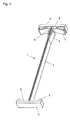
- FIG. 1 shows a protective device 1 for the magnetic train of a synchronous motor
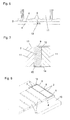
- FIG. 2 shows this protection device 1 in a typical installation situation in a linear motor.
- This protection device in the form of a double-T structure, which can be produced as an injection-molded part, is inserted between the magnets 11, which form the magnetic path of the linear motor on a magnetic carrier 10.
- the protective device 1 has a web 2 which is inserted into the gap between two magnets 11. At both ends of the web 2 are located on both sides of the web 2 at right angles projecting two flanges 3, 4. These flanges are applied to the outer edges of the magnets 11 which are exposed on both sides of the magnetic track.
- first spring elements 6 Formed on the web 2 are found first spring elements 6, the task of which is to center the web 2 in the gap between two magnets 11.
- the protective device 1 can be used in magnetic tracks whose magnets 11 have different distances, in which the gap between two magnets 11 is therefore different in size.
- the magnetic track is curved in its plane, that is to say the gap between the magnets 11 is V-shaped.
- the web 2 must then be so thin that it fits at the narrowest point (ie at the inner radius of a curved magnetic path) between the magnets 11, in the wider areas of the gap then center the first spring elements 6 the web.
- the function of the first spring elements 6 can alternatively be taken over by the web 2 itself if it consists of an elastic, compressible material, and thereby itself becomes a spring element.
- additional spring elements 6 may be useful, which are distributed along the web 2.
- the first flange 3 has second spring elements 7 on its side facing the outer edge of the magnets 11. These second spring elements 7 ensure a secure hold of the protective device 1 to the magnet 11 and compensate for small fluctuations in the dimensions of the magnets 11 transverse to the magnetic field direction.
- projections 5 are formed, which face the outer edges of the magnets 11. These projections 5 ensure a defined contact between the second flange 4 and the magnets 11, which is in particular independent of the radius of curvature of the magnetic track.
- First and second flange 3, 4 each have an edge 8, which together serve a channel for receiving a cover, as is known in the prior art, and as shown in the Figures 3 . 5 and 7 will be shown.
- the edge 8 is in each case formed such that the protective device 1 is formed lower on the side of the edge 8 facing the magnets 11 than beyond the edge 8. The cover is thus guided, and injuries to sharp edges of the cover are avoided.
- a ridge 9 is formed on the top of the web 2, which ensures a defined stop for the impact of two covers of the magnetic train. This is related below with the FIG. 7 shown again in more detail.
- FIG. 2 It is shown that a protective device between two magnets 11 is arranged, which sit on both sides of a joint at the two magnetic carrier 10 abut each other.
- the magnets 11 are otherwise protected by a laterally arranged cover strip known from the prior art.
- the magnets 11 are then covered with a cover 12, such as a thin ferromagnetic sheet, which is held by the attraction of the magnets 11.
- a cover 12 such as a thin ferromagnetic sheet, which is held by the attraction of the magnets 11.
- the ridge 9 of the protection device 1 can be seen between the two covers.
- the protective device 1 is made of a compressible material, it may be slightly higher than the magnets 11. Due to the force with which the cover 12 is pulled to the magnets 11, the protective device 1 is then compressed to the correct, the magnet 11 corresponding height.
- FIGS. 2 and 3 is a slight curvature of the magnetic path in the plane of the magnetic path to recognize, resulting in a V-shaped formation of the gap between two magnets 11, as described above.
- the magnetic path may also be curved as in a rotary synchronous motor, where the magnets 11 are arranged on the inside or outside of a cylinder. Again, arise V-shaped gaps between the magnets, wherein the distance between the magnets 11 now varies perpendicular to the plane of the magnetic track.
- I can use the protection device, if it is made of a sufficiently compressible material.
- FIG. 4 shows a magnetic track in which a protective device is inserted between all magnets 11.
- a protective device By the abutting flanges 3, 4 creates a continuous, lateral protection for the magnets 11. A separate mounting as a protection as in the prior art is therefore no longer necessary.
- the edges 8 on the flanges 3, 4 and a channel is formed, in which the cover 12 can be inserted, as in the FIG. 5 shown.
- the ridge 9, which serves as a joint between two covers 12, is only necessary in this arrangement where two covers 12 abut each other.
- FIG. 6 Fig. 3 illustrates the area of the second flange 4 enlarged, showing preferred embodiments.
- the second flanges 4 in an overlap region 13 have corresponding areas in which the individual flange is formed thinner, wherein the two overlapping regions complement each other to a thickness that each flange also outside the overlap region 13 has.
- the illustrated shape of the overlapping portions of the second flanges is an example, other shapes are possible, such as corresponding bevels or tongue and groove structures.
- the example shown has the particular advantage that the distance between the flanges 3, 4 of individual protection elements 1 can change (in particular: increase) without a gap being created. This is advantageous for curved magnetic paths at the outer radius.
- FIG. 7 shows a section through the protective device 1, which is inserted between two magnets 11. It can be seen a recess 15 in the form of a chamfer on both sides of the web 2, on the magnetic carrier 10 facing bottom. Other shapes than a simple bevel are also possible. Thus, space is created for excess adhesive 14, which emerges when attaching the magnets 11 on the carrier 10 side of the magnets 11.
- An end piece 16 completely encloses the edges of a magnet 11, that is, instead of a web 2, it has two. These webs also have on the sides facing the magnets 11 first and second spring-end elements 6, 7, and a first and second flange 3, 4, each of which protects the neighboring magnet in part. Overlap areas 13 with the adjacent protective devices 1 are also provided.
- edges 8 of the flanges 3, 4 are continued on the outer, additional web 2, which protects the last magnet 11 on the end face of the magnetic path, so that there is a cover 12 after the last magnet 11 on and can rest. A bending of the cover 12 around the edge of the last magnet is therefore superfluous. The cover 12 also can not slip.
Landscapes
- Engineering & Computer Science (AREA)
- Power Engineering (AREA)
- Physics & Mathematics (AREA)
- Chemical & Material Sciences (AREA)
- Combustion & Propulsion (AREA)
- Electromagnetism (AREA)
- Linear Motors (AREA)
Priority Applications (3)
| Application Number | Priority Date | Filing Date | Title |
|---|---|---|---|
| EP14171949.2A EP2955824B1 (fr) | 2014-06-11 | 2014-06-11 | Élément secondaire d'un moteur synchrone doté d'un dispositif de protection pour aimants |
| IL238830A IL238830B (en) | 2014-06-11 | 2015-05-14 | Secondary part of a synchronous motor having a protective device for magnets |
| US14/735,551 US9768659B2 (en) | 2014-06-11 | 2015-06-10 | Secondary part of a synchronous motor having a protective device for magnets |
Applications Claiming Priority (1)
| Application Number | Priority Date | Filing Date | Title |
|---|---|---|---|
| EP14171949.2A EP2955824B1 (fr) | 2014-06-11 | 2014-06-11 | Élément secondaire d'un moteur synchrone doté d'un dispositif de protection pour aimants |
Publications (2)
| Publication Number | Publication Date |
|---|---|
| EP2955824A1 true EP2955824A1 (fr) | 2015-12-16 |
| EP2955824B1 EP2955824B1 (fr) | 2017-05-31 |
Family
ID=50927976
Family Applications (1)
| Application Number | Title | Priority Date | Filing Date |
|---|---|---|---|
| EP14171949.2A Active EP2955824B1 (fr) | 2014-06-11 | 2014-06-11 | Élément secondaire d'un moteur synchrone doté d'un dispositif de protection pour aimants |
Country Status (3)
| Country | Link |
|---|---|
| US (1) | US9768659B2 (fr) |
| EP (1) | EP2955824B1 (fr) |
| IL (1) | IL238830B (fr) |
Families Citing this family (2)
| Publication number | Priority date | Publication date | Assignee | Title |
|---|---|---|---|---|
| JP6378276B2 (ja) | 2016-09-30 | 2018-08-22 | ファナック株式会社 | 磁石板を覆うカバー部材を備えたリニアモータ用磁石アセンブリ |
| DE102018118814B4 (de) | 2018-08-02 | 2024-07-18 | Beckhoff Automation Gmbh | Verfahren zum Identifizieren eines Schlittens eines linearen Transportsystems |
Citations (5)
| Publication number | Priority date | Publication date | Assignee | Title |
|---|---|---|---|---|
| US5642013A (en) | 1994-11-16 | 1997-06-24 | Wavre; Nicolas | Permanent-magnet synchronous motor |
| US5952742A (en) | 1995-02-03 | 1999-09-14 | Krauss-Maffei Ag | Synchronous linear motor with improved means for positioning and fastening permanent magnets |
| US6882065B2 (en) | 2000-08-31 | 2005-04-19 | Etel Sa | Linear motor assembly and method for mounting a linear motor assembly |
| JP2009038869A (ja) | 2007-07-31 | 2009-02-19 | Hitachi Ltd | リニアモータ |
| US20140062223A1 (en) * | 2012-09-03 | 2014-03-06 | Industry-Academic Cooperation Foundation, Yonsei University | Linear generator and method for generating power using the same |
Family Cites Families (6)
| Publication number | Priority date | Publication date | Assignee | Title |
|---|---|---|---|---|
| US4827163A (en) * | 1986-03-04 | 1989-05-02 | Mechanical Technology Incorporated | Monocoil reciprocating permanent magnet electric machine with self-centering force |
| FI113308B (fi) * | 2001-06-14 | 2004-03-31 | Abb Oy | Kestomagneettielementti ja sähkökone |
| CA2620345A1 (fr) * | 2005-08-25 | 2007-03-01 | Power Group International, Inc. | Dispositif et procede de blocage et de verrouillage d'aimants permanents et d'amelioration du refroidissement dans une machine electrique rotative |
| DE102006049825B4 (de) * | 2006-10-21 | 2012-10-25 | Esw Gmbh | Anordnung zur Befestigung von Permanentmagneten an schnell drehenden Rotoren von elektrischen Maschinen |
| US8541923B2 (en) * | 2009-03-05 | 2013-09-24 | Cpm Compact Power Motors Gmbh | Dual-rotor motor having heat dissipation |
| JP5877777B2 (ja) * | 2012-09-26 | 2016-03-08 | 日立オートモティブシステムズ株式会社 | 回転電機、磁極ピース製造方法 |
-
2014
- 2014-06-11 EP EP14171949.2A patent/EP2955824B1/fr active Active
-
2015
- 2015-05-14 IL IL238830A patent/IL238830B/en active IP Right Grant
- 2015-06-10 US US14/735,551 patent/US9768659B2/en active Active
Patent Citations (5)
| Publication number | Priority date | Publication date | Assignee | Title |
|---|---|---|---|---|
| US5642013A (en) | 1994-11-16 | 1997-06-24 | Wavre; Nicolas | Permanent-magnet synchronous motor |
| US5952742A (en) | 1995-02-03 | 1999-09-14 | Krauss-Maffei Ag | Synchronous linear motor with improved means for positioning and fastening permanent magnets |
| US6882065B2 (en) | 2000-08-31 | 2005-04-19 | Etel Sa | Linear motor assembly and method for mounting a linear motor assembly |
| JP2009038869A (ja) | 2007-07-31 | 2009-02-19 | Hitachi Ltd | リニアモータ |
| US20140062223A1 (en) * | 2012-09-03 | 2014-03-06 | Industry-Academic Cooperation Foundation, Yonsei University | Linear generator and method for generating power using the same |
Also Published As
| Publication number | Publication date |
|---|---|
| US9768659B2 (en) | 2017-09-19 |
| EP2955824B1 (fr) | 2017-05-31 |
| IL238830B (en) | 2020-01-30 |
| US20150364965A1 (en) | 2015-12-17 |
Similar Documents
| Publication | Publication Date | Title |
|---|---|---|
| WO2000008270A1 (fr) | Cloison mobile | |
| EP0329843A1 (fr) | Boîtier pour appareil électrique | |
| EP2955824B1 (fr) | Élément secondaire d'un moteur synchrone doté d'un dispositif de protection pour aimants | |
| EP2377791A2 (fr) | Unité de transport | |
| EP2334887B1 (fr) | Connecteur à fiche | |
| DE102012206288A1 (de) | Verkleidung einer Innenseite einer Seitenwand eines Schienenfahrzeugs | |
| DE19524810A1 (de) | Anordnung zum Verschließen von Bohrungen in einer Führungsschiene | |
| EP0054177B1 (fr) | Dispositif de liaison de deux éléments de construction | |
| DE102015225259A1 (de) | Segmentwälzlager und Scheibenbremsenvorrichtung | |
| EP3197031B1 (fr) | Bande magnetique pour un dispositif de transport | |
| EP1569312A2 (fr) | Element de construction pour une canalisation de cables | |
| DE2951225C2 (de) | Federsatz eines Relais mit biegungsgeschwächten Kontaktfedern | |
| DE102016000396A1 (de) | Positioniervorrichtung zum positionierten Festlegen von strangförmigen Komponenten | |
| EP2630708B1 (fr) | Système d'aide au montage | |
| EP2515440A2 (fr) | Capteur de proximité ou de rapprochement inductif | |
| EP0525661A1 (fr) | Coffrage pour construction en béton ainsi que proocédé pour la fabrication du coffrage | |
| DE19609480B4 (de) | Kabelkanaldeckel | |
| DE102024122819A1 (de) | Explosionsgeschütztes Gehäuse | |
| EP3318385B1 (fr) | Utilisation d'un dispositif et procédé de fixation des conduits dans les canaux d'outils | |
| DE29522090U1 (de) | Anordnung zum Verschließen von Bohrungen in einer Führungsschiene | |
| DE102016103316B4 (de) | Schienenbefestigungssystem | |
| AT400873B (de) | Türpfosten-steckwinkel | |
| DE102013007674A1 (de) | Austauschbare Schutzabdeckung für Linearmotor-Sekundärteil | |
| DE202005006411U1 (de) | Metallische Flachdichtung mit Halterungslaschen | |
| DE102013005703A1 (de) | Bauplatte |
Legal Events
| Date | Code | Title | Description |
|---|---|---|---|
| PUAI | Public reference made under article 153(3) epc to a published international application that has entered the european phase |
Free format text: ORIGINAL CODE: 0009012 |
|
| AK | Designated contracting states |
Kind code of ref document: A1 Designated state(s): AL AT BE BG CH CY CZ DE DK EE ES FI FR GB GR HR HU IE IS IT LI LT LU LV MC MK MT NL NO PL PT RO RS SE SI SK SM TR |
|
| AX | Request for extension of the european patent |
Extension state: BA ME |
|
| 17P | Request for examination filed |
Effective date: 20160616 |
|
| RBV | Designated contracting states (corrected) |
Designated state(s): AL AT BE BG CH CY CZ DE DK EE ES FI FR GB GR HR HU IE IS IT LI LT LU LV MC MK MT NL NO PL PT RO RS SE SI SK SM TR |
|
| GRAP | Despatch of communication of intention to grant a patent |
Free format text: ORIGINAL CODE: EPIDOSNIGR1 |
|
| STAA | Information on the status of an ep patent application or granted ep patent |
Free format text: STATUS: GRANT OF PATENT IS INTENDED |
|
| RIC1 | Information provided on ipc code assigned before grant |
Ipc: H02K 41/03 20060101AFI20170126BHEP Ipc: H02K 1/17 20060101ALN20170126BHEP |
|
| INTG | Intention to grant announced |
Effective date: 20170217 |
|
| GRAS | Grant fee paid |
Free format text: ORIGINAL CODE: EPIDOSNIGR3 |
|
| GRAA | (expected) grant |
Free format text: ORIGINAL CODE: 0009210 |
|
| STAA | Information on the status of an ep patent application or granted ep patent |
Free format text: STATUS: THE PATENT HAS BEEN GRANTED |
|
| AK | Designated contracting states |
Kind code of ref document: B1 Designated state(s): AL AT BE BG CH CY CZ DE DK EE ES FI FR GB GR HR HU IE IS IT LI LT LU LV MC MK MT NL NO PL PT RO RS SE SI SK SM TR |
|
| REG | Reference to a national code |
Ref country code: CH Ref legal event code: EP Ref country code: GB Ref legal event code: FG4D Free format text: NOT ENGLISH |
|
| REG | Reference to a national code |
Ref country code: AT Ref legal event code: REF Ref document number: 898257 Country of ref document: AT Kind code of ref document: T Effective date: 20170615 |
|
| REG | Reference to a national code |
Ref country code: FR Ref legal event code: PLFP Year of fee payment: 4 |
|
| REG | Reference to a national code |
Ref country code: IE Ref legal event code: FG4D Free format text: LANGUAGE OF EP DOCUMENT: GERMAN |
|
| REG | Reference to a national code |
Ref country code: DE Ref legal event code: R096 Ref document number: 502014003982 Country of ref document: DE |
|
| REG | Reference to a national code |
Ref country code: CH Ref legal event code: NV Representative=s name: ICB INGENIEURS CONSEILS EN BREVETS SA, CH |
|
| REG | Reference to a national code |
Ref country code: NL Ref legal event code: FP |
|
| REG | Reference to a national code |
Ref country code: LT Ref legal event code: MG4D |
|
| PG25 | Lapsed in a contracting state [announced via postgrant information from national office to epo] |
Ref country code: FI Free format text: LAPSE BECAUSE OF FAILURE TO SUBMIT A TRANSLATION OF THE DESCRIPTION OR TO PAY THE FEE WITHIN THE PRESCRIBED TIME-LIMIT Effective date: 20170531 Ref country code: NO Free format text: LAPSE BECAUSE OF FAILURE TO SUBMIT A TRANSLATION OF THE DESCRIPTION OR TO PAY THE FEE WITHIN THE PRESCRIBED TIME-LIMIT Effective date: 20170831 Ref country code: HR Free format text: LAPSE BECAUSE OF FAILURE TO SUBMIT A TRANSLATION OF THE DESCRIPTION OR TO PAY THE FEE WITHIN THE PRESCRIBED TIME-LIMIT Effective date: 20170531 Ref country code: GR Free format text: LAPSE BECAUSE OF FAILURE TO SUBMIT A TRANSLATION OF THE DESCRIPTION OR TO PAY THE FEE WITHIN THE PRESCRIBED TIME-LIMIT Effective date: 20170901 Ref country code: LT Free format text: LAPSE BECAUSE OF FAILURE TO SUBMIT A TRANSLATION OF THE DESCRIPTION OR TO PAY THE FEE WITHIN THE PRESCRIBED TIME-LIMIT Effective date: 20170531 Ref country code: ES Free format text: LAPSE BECAUSE OF FAILURE TO SUBMIT A TRANSLATION OF THE DESCRIPTION OR TO PAY THE FEE WITHIN THE PRESCRIBED TIME-LIMIT Effective date: 20170531 |
|
| PG25 | Lapsed in a contracting state [announced via postgrant information from national office to epo] |
Ref country code: BG Free format text: LAPSE BECAUSE OF FAILURE TO SUBMIT A TRANSLATION OF THE DESCRIPTION OR TO PAY THE FEE WITHIN THE PRESCRIBED TIME-LIMIT Effective date: 20170831 Ref country code: SE Free format text: LAPSE BECAUSE OF FAILURE TO SUBMIT A TRANSLATION OF THE DESCRIPTION OR TO PAY THE FEE WITHIN THE PRESCRIBED TIME-LIMIT Effective date: 20170531 Ref country code: IS Free format text: LAPSE BECAUSE OF FAILURE TO SUBMIT A TRANSLATION OF THE DESCRIPTION OR TO PAY THE FEE WITHIN THE PRESCRIBED TIME-LIMIT Effective date: 20170930 Ref country code: RS Free format text: LAPSE BECAUSE OF FAILURE TO SUBMIT A TRANSLATION OF THE DESCRIPTION OR TO PAY THE FEE WITHIN THE PRESCRIBED TIME-LIMIT Effective date: 20170531 Ref country code: LV Free format text: LAPSE BECAUSE OF FAILURE TO SUBMIT A TRANSLATION OF THE DESCRIPTION OR TO PAY THE FEE WITHIN THE PRESCRIBED TIME-LIMIT Effective date: 20170531 |
|
| PG25 | Lapsed in a contracting state [announced via postgrant information from national office to epo] |
Ref country code: RO Free format text: LAPSE BECAUSE OF FAILURE TO SUBMIT A TRANSLATION OF THE DESCRIPTION OR TO PAY THE FEE WITHIN THE PRESCRIBED TIME-LIMIT Effective date: 20170531 Ref country code: DK Free format text: LAPSE BECAUSE OF FAILURE TO SUBMIT A TRANSLATION OF THE DESCRIPTION OR TO PAY THE FEE WITHIN THE PRESCRIBED TIME-LIMIT Effective date: 20170531 Ref country code: CZ Free format text: LAPSE BECAUSE OF FAILURE TO SUBMIT A TRANSLATION OF THE DESCRIPTION OR TO PAY THE FEE WITHIN THE PRESCRIBED TIME-LIMIT Effective date: 20170531 Ref country code: SK Free format text: LAPSE BECAUSE OF FAILURE TO SUBMIT A TRANSLATION OF THE DESCRIPTION OR TO PAY THE FEE WITHIN THE PRESCRIBED TIME-LIMIT Effective date: 20170531 Ref country code: EE Free format text: LAPSE BECAUSE OF FAILURE TO SUBMIT A TRANSLATION OF THE DESCRIPTION OR TO PAY THE FEE WITHIN THE PRESCRIBED TIME-LIMIT Effective date: 20170531 |
|
| PG25 | Lapsed in a contracting state [announced via postgrant information from national office to epo] |
Ref country code: PL Free format text: LAPSE BECAUSE OF FAILURE TO SUBMIT A TRANSLATION OF THE DESCRIPTION OR TO PAY THE FEE WITHIN THE PRESCRIBED TIME-LIMIT Effective date: 20170531 Ref country code: SM Free format text: LAPSE BECAUSE OF FAILURE TO SUBMIT A TRANSLATION OF THE DESCRIPTION OR TO PAY THE FEE WITHIN THE PRESCRIBED TIME-LIMIT Effective date: 20170531 |
|
| REG | Reference to a national code |
Ref country code: DE Ref legal event code: R097 Ref document number: 502014003982 Country of ref document: DE |
|
| REG | Reference to a national code |
Ref country code: IE Ref legal event code: MM4A |
|
| PLBE | No opposition filed within time limit |
Free format text: ORIGINAL CODE: 0009261 |
|
| STAA | Information on the status of an ep patent application or granted ep patent |
Free format text: STATUS: NO OPPOSITION FILED WITHIN TIME LIMIT |
|
| PG25 | Lapsed in a contracting state [announced via postgrant information from national office to epo] |
Ref country code: IE Free format text: LAPSE BECAUSE OF NON-PAYMENT OF DUE FEES Effective date: 20170611 Ref country code: LU Free format text: LAPSE BECAUSE OF NON-PAYMENT OF DUE FEES Effective date: 20170611 |
|
| REG | Reference to a national code |
Ref country code: BE Ref legal event code: MM Effective date: 20170630 |
|
| 26N | No opposition filed |
Effective date: 20180301 |
|
| PG25 | Lapsed in a contracting state [announced via postgrant information from national office to epo] |
Ref country code: SI Free format text: LAPSE BECAUSE OF FAILURE TO SUBMIT A TRANSLATION OF THE DESCRIPTION OR TO PAY THE FEE WITHIN THE PRESCRIBED TIME-LIMIT Effective date: 20170531 |
|
| REG | Reference to a national code |
Ref country code: FR Ref legal event code: PLFP Year of fee payment: 5 |
|
| PG25 | Lapsed in a contracting state [announced via postgrant information from national office to epo] |
Ref country code: BE Free format text: LAPSE BECAUSE OF NON-PAYMENT OF DUE FEES Effective date: 20170630 |
|
| PG25 | Lapsed in a contracting state [announced via postgrant information from national office to epo] |
Ref country code: MT Free format text: LAPSE BECAUSE OF FAILURE TO SUBMIT A TRANSLATION OF THE DESCRIPTION OR TO PAY THE FEE WITHIN THE PRESCRIBED TIME-LIMIT Effective date: 20170531 |
|
| GBPC | Gb: european patent ceased through non-payment of renewal fee |
Effective date: 20180611 |
|
| PG25 | Lapsed in a contracting state [announced via postgrant information from national office to epo] |
Ref country code: GB Free format text: LAPSE BECAUSE OF NON-PAYMENT OF DUE FEES Effective date: 20180611 |
|
| PG25 | Lapsed in a contracting state [announced via postgrant information from national office to epo] |
Ref country code: MC Free format text: LAPSE BECAUSE OF FAILURE TO SUBMIT A TRANSLATION OF THE DESCRIPTION OR TO PAY THE FEE WITHIN THE PRESCRIBED TIME-LIMIT Effective date: 20170531 Ref country code: HU Free format text: LAPSE BECAUSE OF FAILURE TO SUBMIT A TRANSLATION OF THE DESCRIPTION OR TO PAY THE FEE WITHIN THE PRESCRIBED TIME-LIMIT; INVALID AB INITIO Effective date: 20140611 |
|
| PG25 | Lapsed in a contracting state [announced via postgrant information from national office to epo] |
Ref country code: CY Free format text: LAPSE BECAUSE OF FAILURE TO SUBMIT A TRANSLATION OF THE DESCRIPTION OR TO PAY THE FEE WITHIN THE PRESCRIBED TIME-LIMIT Effective date: 20170531 |
|
| PG25 | Lapsed in a contracting state [announced via postgrant information from national office to epo] |
Ref country code: MK Free format text: LAPSE BECAUSE OF FAILURE TO SUBMIT A TRANSLATION OF THE DESCRIPTION OR TO PAY THE FEE WITHIN THE PRESCRIBED TIME-LIMIT Effective date: 20170531 |
|
| PG25 | Lapsed in a contracting state [announced via postgrant information from national office to epo] |
Ref country code: TR Free format text: LAPSE BECAUSE OF FAILURE TO SUBMIT A TRANSLATION OF THE DESCRIPTION OR TO PAY THE FEE WITHIN THE PRESCRIBED TIME-LIMIT Effective date: 20170531 |
|
| PG25 | Lapsed in a contracting state [announced via postgrant information from national office to epo] |
Ref country code: PT Free format text: LAPSE BECAUSE OF FAILURE TO SUBMIT A TRANSLATION OF THE DESCRIPTION OR TO PAY THE FEE WITHIN THE PRESCRIBED TIME-LIMIT Effective date: 20170531 |
|
| PG25 | Lapsed in a contracting state [announced via postgrant information from national office to epo] |
Ref country code: AL Free format text: LAPSE BECAUSE OF FAILURE TO SUBMIT A TRANSLATION OF THE DESCRIPTION OR TO PAY THE FEE WITHIN THE PRESCRIBED TIME-LIMIT Effective date: 20170531 |
|
| PGFP | Annual fee paid to national office [announced via postgrant information from national office to epo] |
Ref country code: DE Payment date: 20250618 Year of fee payment: 12 |
|
| PGFP | Annual fee paid to national office [announced via postgrant information from national office to epo] |
Ref country code: NL Payment date: 20250618 Year of fee payment: 12 |
|
| PGFP | Annual fee paid to national office [announced via postgrant information from national office to epo] |
Ref country code: FR Payment date: 20250625 Year of fee payment: 12 |
|
| PGFP | Annual fee paid to national office [announced via postgrant information from national office to epo] |
Ref country code: AT Payment date: 20250620 Year of fee payment: 12 |
|
| PGFP | Annual fee paid to national office [announced via postgrant information from national office to epo] |
Ref country code: IT Payment date: 20250624 Year of fee payment: 12 |
|
| PGFP | Annual fee paid to national office [announced via postgrant information from national office to epo] |
Ref country code: CH Payment date: 20250701 Year of fee payment: 12 |
|
| REG | Reference to a national code |
Ref country code: CH Ref legal event code: R17 Free format text: ST27 STATUS EVENT CODE: U-0-0-R10-R17 (AS PROVIDED BY THE NATIONAL OFFICE) Effective date: 20260108 |