EP2955856A1 - Nouvelle(s) technique(s) de rssi à bande étroite pour l'atténuation d'interférence de satellites adjacents - Google Patents
Nouvelle(s) technique(s) de rssi à bande étroite pour l'atténuation d'interférence de satellites adjacents Download PDFInfo
- Publication number
- EP2955856A1 EP2955856A1 EP15170496.2A EP15170496A EP2955856A1 EP 2955856 A1 EP2955856 A1 EP 2955856A1 EP 15170496 A EP15170496 A EP 15170496A EP 2955856 A1 EP2955856 A1 EP 2955856A1
- Authority
- EP
- European Patent Office
- Prior art keywords
- signal
- band
- interest
- antenna
- filter
- Prior art date
- Legal status (The legal status is an assumption and is not a legal conclusion. Google has not performed a legal analysis and makes no representation as to the accuracy of the status listed.)
- Granted
Links
Images

Classifications
-
- H—ELECTRICITY
- H04—ELECTRIC COMMUNICATION TECHNIQUE
- H04B—TRANSMISSION
- H04B1/00—Details of transmission systems, not covered by a single one of groups H04B3/00 - H04B13/00; Details of transmission systems not characterised by the medium used for transmission
- H04B1/06—Receivers
- H04B1/10—Means associated with receiver for limiting or suppressing noise or interference
- H04B1/1027—Means associated with receiver for limiting or suppressing noise or interference assessing signal quality or detecting noise/interference for the received signal
- H04B1/1036—Means associated with receiver for limiting or suppressing noise or interference assessing signal quality or detecting noise/interference for the received signal with automatic suppression of narrow band noise or interference, e.g. by using tuneable notch filters
-
- G—PHYSICS
- G01—MEASURING; TESTING
- G01S—RADIO DIRECTION-FINDING; RADIO NAVIGATION; DETERMINING DISTANCE OR VELOCITY BY USE OF RADIO WAVES; LOCATING OR PRESENCE-DETECTING BY USE OF THE REFLECTION OR RERADIATION OF RADIO WAVES; ANALOGOUS ARRANGEMENTS USING OTHER WAVES
- G01S3/00—Direction-finders for determining the direction from which infrasonic, sonic, ultrasonic or electromagnetic waves, or particle emission, not having a directional significance, are being received
- G01S3/02—Direction-finders for determining the direction from which infrasonic, sonic, ultrasonic or electromagnetic waves, or particle emission, not having a directional significance, are being received using radio waves
- G01S3/04—Details
-
- G—PHYSICS
- G01—MEASURING; TESTING
- G01S—RADIO DIRECTION-FINDING; RADIO NAVIGATION; DETERMINING DISTANCE OR VELOCITY BY USE OF RADIO WAVES; LOCATING OR PRESENCE-DETECTING BY USE OF THE REFLECTION OR RERADIATION OF RADIO WAVES; ANALOGOUS ARRANGEMENTS USING OTHER WAVES
- G01S3/00—Direction-finders for determining the direction from which infrasonic, sonic, ultrasonic or electromagnetic waves, or particle emission, not having a directional significance, are being received
- G01S3/02—Direction-finders for determining the direction from which infrasonic, sonic, ultrasonic or electromagnetic waves, or particle emission, not having a directional significance, are being received using radio waves
- G01S3/14—Systems for determining direction or deviation from predetermined direction
- G01S3/38—Systems for determining direction or deviation from predetermined direction using adjustment of real or effective orientation of directivity characteristic of an antenna or an antenna system to give a desired condition of signal derived from that antenna or antenna system, e.g. to give a maximum or minimum signal
-
- H—ELECTRICITY
- H04—ELECTRIC COMMUNICATION TECHNIQUE
- H04B—TRANSMISSION
- H04B7/00—Radio transmission systems, i.e. using radiation field
- H04B7/14—Relay systems
- H04B7/15—Active relay systems
- H04B7/185—Space-based or airborne stations; Stations for satellite systems
- H04B7/1851—Systems using a satellite or space-based relay
-
- H—ELECTRICITY
- H04—ELECTRIC COMMUNICATION TECHNIQUE
- H04B—TRANSMISSION
- H04B1/00—Details of transmission systems, not covered by a single one of groups H04B3/00 - H04B13/00; Details of transmission systems not characterised by the medium used for transmission
- H04B1/06—Receivers
- H04B1/10—Means associated with receiver for limiting or suppressing noise or interference
- H04B1/1027—Means associated with receiver for limiting or suppressing noise or interference assessing signal quality or detecting noise/interference for the received signal
- H04B2001/1063—Means associated with receiver for limiting or suppressing noise or interference assessing signal quality or detecting noise/interference for the received signal using a notch filter
Definitions
- INSs Inertial Navigation Systems
- INSs Inertial Navigation Systems
- Such geo-location and attitude information coupled with angular position sensors (which describe the angular relationship between an antenna Line-of-Sight (LOS)) and detailed ephemeris information (which describes the location and inclination of the satellite of interest), can be used to compute pointing angles needed to point the earth-station antenna at the satellite of interest.
- LOS Line-of-Sight
- ephemeris information which describes the location and inclination of the satellite of interest
- RSSI Received Signal Strength Indicator
- RSSIs measure a power level that a Radio Frequency (RF) device is receiving from a radio infrastructure at a given location and time.
- RSSIs often employ a broad-spectrum envelope power detector to sense the RF energy from a whole satellite transponder or from all the transponders on a particular satellite. Based on the received signal strength, the pointing angles for the antenna can be calculated.
- Yet another option for determining the pointing angles is to use an envelope power detector to first find a certain, particularly strong satellite signal on a Direct Broadcast Satellite (DBS) service. Pointing then can be offset from the found signal to find the actual satellite of interest.
- DBS Direct Broadcast Satellite
- beacon receivers Another class of systems use beacon receivers to help solve the problem of properly pointing the earth-station antenna. This often introduces considerable cost and complexity to the system since beacon receivers operate on very low power satellite signals which, in turn, require that the beacon receiver have an exceptionally narrow bandwidth (on the order of a few hundred Hz for a small aperture antenna). This makes such systems extremely vulnerable to clock drift and Doppler frequency shift, and usually requires the use of Phase Lock Loop Low Noise Blocks (LNBs) along with a precision, temperature compensated ten MHz reference.
- LNBs Phase Lock Loop Low Noise Blocks
- the beacon to be tracked is usually found on one of the two possible polarizations, and is often located on the satellite transponder band edge. Further, not all satellites of interest are equipped or even provisioned to provide a suitable beacon signal.
- some systems require the use of costly, large and heavy, narrow beamwidth antennas, which have beamwidths less than the angular spacing of the geo-stationary satellites.
- Use of such narrow-beam antennas can introduce significant challenges in the acquisition and tracking of satellites, especially for on-the-move systems.
- NbRSSI narrow-band RSSI
- the device and method in accordance with the present disclosure can solve the problem of optimally pointing an earth-station antenna and specifically the locating of, pointing to, and tracking of a Radio Frequency or Intermediate Frequency (IF) signal from an earth-orbiting satellite.
- the device and method in accordance with the present disclosure are useful with wide beamwidth antennas, which have beamwidths greater than the angular spacing of geo-stationary satel-lites. In this regard, interference that comes from the presence of adjacent satellites transmitting in the same RF band can be suppressed.
- the components required to realize the design in accordance with the present disclosure are small, low-cost, and low-power. This allows narrow- band RSSI features to be incorporated into a wide variety of embedded systems where size, weight, power and cost are critical design parameters.
- a method for tracking a signal of interest from a signal transmitting device is provided, the method being performed using an antenna to scan for the signal of interest.
- the method includes selecting a filter from a filter bank including a plurality of filters having at least two filters with different bandwidths, wherein the selected filter is a filter having a largest bandwidth of the plurality of filters that is equal to or less than a bandwidth of the signal of interest.
- the method includes determining the presence of other transmitting devices within a beamwidth of the antenna, and when other transmitting devices are not within the beamwidth of the antenna selecting includes selecting a filter having a largest bandwidth of the plurality of filters that is equal to or less than a carrier signal of the signal of interest.
- the method includes determining the presence of other transmitting devices within a beamwidth of the antenna, and when other transmitting devices are within the beamwidth of the antenna, determining if the additional transmitting devices have signals present within a band of interest.
- selecting a filter includes selecting a filter of the plurality of filters having a largest bandwidth that is equal to or less than a null-band of the signal of interest.
- the method includes using a narrow-band null search methodology to track the null-band on the signal of interest.
- the method when the additional transmitting devices do not have signals present within a band of interest, the method includes determining if the transmitting device has a signal at a center transponder band.
- the method includes using a narrow band null search to track the signal at the center transponder band.
- the method when the transmitting device does not have a signal at a center transponder band, the method includes requesting a satellite service operator create a pseudo-beacon signal at a band unused by other transmitting devices within the antenna beam width.
- selecting a filter includes selecting a filter of the plurality of filters having a largest bandwidth that is equal to or less than the pseudo-beacon signal.
- the method includes using a narrow band pseudo-beacon receiver methodology to track the pseudo-beacon signal on the signal of interest.
- the method includes using an antenna having a beamwidth greater than an angular spacing of geo-stationary transmitting devices.
- the controller is configured to determine the presence of other transmitting devices within a beamwidth of the antenna, and when other transmitting devices are not within the beam width of the antenna, select a filter having a largest bandwidth of the plurality of filters that is equal to or less than a carrier signal of the signal of interest.
- the controller is configured to determine the presence of other transmitting devices within a beamwidth of the antenna, and when other transmitting devices are within the beam width of the antenna, determine if the additional transmitting devices have signals present within a band of interest.
- the controller is configured to request a satellite service operator to creates a null-band on the signal of interest when the additional transmitting devices have signals present within a band of interest.
- the controller is configured to select a filter of the plurality of filters having a largest bandwidth that is equal to or less than the null-band of the signal of interest.
- the controller is configured to use a narrow-band null search methodology to track the null-band on the signal of interest.
- the controller is configured to select a filter of the plurality of filters having a largest bandwidth that is equal to or less than a transponder stop-band of the signal of interest when the transmitting device has a signal at a center transponder band.
- the controller is configured to use a narrow-band null search to track the signal at the center transponder band.
- the controller is configured to select a filter of the plurality of filters having a largest bandwidth that is equal to or less than the pseudo-beacon signal.
- the controller is configured to use a narrow-band pseudo-beacon receiver methodology to track the pseudo-beacon signal on the signal of interest.
- the receiver circuit comprises: a mixer for mixing a plurality of signals; a local oscillator circuit having an output electrically connected to a first input of the mixer; and a clock circuit electrically connected to the local oscillator output.
- the clock circuit comprises: an oscillator; a global positioning system (GPS) receiver; and a counter including a count input for counting a number of pulses and a reset input for resetting the counted number of pulses, wherein an output of the local oscillator is operatively coupled to the count input, and the output of the GPS receiver is operatively coupled to the reset input.
- GPS global positioning system
- an antenna acquisition and tracking positioning system for communicating with a satellite of a plurality of satellites includes: an antenna including an output for outputting a received a signal; the NbRSSI circuit as described herein operatively coupled to the antenna output; and positioning circuitry operatively coupled to an output of the NbRSSI circuit, the circuitry operative to command a position of the antenna based on data received from the NbRSSI circuit.
- the positioning circuitry comprises a processor and memory, and positioning logic stored in the memory and executable by the processor, wherein when executed by the processor the positioning logic causes the processor to control a position of the antenna based on the output of the NbRSSI circuit.
- a beamwidth of the antenna is greater than an angular spacing of the plurality of satellites.
- the actuator comprises a motor and a motor controller.
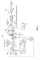
- the circuit 30 enables an antenna acquisition and tracking system to find and track a particular carrier frequency.
- the circuit 30 uses a simple, low cost receiver 32 to convert the incoming Intermediate Frequency signal 12 down to baseband, which is typically 4 MHz and below, via mixer 14.
- the receiver 32 can be set to look at a particular frequency band via a software-controlled Local Oscillator 16 that is tied to a high frequency stability clock source 34, which may be formed by a Global Positioning System (GPS) receiver 34a, an inexpensive oscillator 34c and a counter 34b.
- GPS Global Positioning System
- circuitry will be understood to refer to both hardware circuits (e.g., circuits formed from discrete components and/or ASICs) as well as micro-processor based circuits that execute logic in the form of code stored in memory.
- a suitably fast Analog-to-Digital Converter can be used at any point along the path of the circuit and all subsequent steps can be performed in software.
- ADC Analog-to-Digital Converter
- Selectable filters 36a-36n of various bandwidths allow maximization of Signal to Noise Ratio. Signals out of band are rejected, which improves pointing accuracy. Sources of frequency drift such as Doppler shift and clock drift are compensated for using the clock source 34 or alternative methodology, which enables the use of tighter filters and in turn allows for higher Signal to Noise Ratio.
- the described invention can provide interference suppression benefits when employed in non-geo-stationary (NGSO) satellite systems as well where interference with adjacent NGSO and adjacent GSO satellites is of increased concern due to the relative movement of NGSO satellites as observed from earth.
- GSO geo-stationary orbit
- FIG. 3 illustrated is a block diagram of an antenna pointing and tracking system 50 that incorporates a narrow-band RSSI circuit 30 in accordance with the present disclosure.
- An input of the RSSI circuit 30 in accordance with the present disclosure is coupled to a signal output of antenna 52.
- An output of the RSSI circuit 30 is operatively coupled to a processor 54 and memory 54a, which may be a PLC or other smart controller.
- Stored in the memory 54a and executable by the processor 54 may be logic for carrying various operations, including selection of the one or more filters 36a-36n, positioning the antenna 52 and tracking a signal of interest.
- the processor 54 can include positioning circuitry that, based on the data from the RSSI circuit 30, determines whether or not the antenna 52 should be repositioned in order to obtain an improved signal. Positioning of the antenna 52 can be based on the signal strength, as described below with respect to Figure 4 . Should the antenna 52 require repositioning, the processor 54 can provide a position command to an actuator, which may be embodied as a motor controller 56 and motor (or motors) 58, so as to alter a position of the antenna 52 to correspond to the commanded position.
- an actuator which may be embodied as a motor controller 56 and motor (or motors) 58, so as to alter a position of the antenna 52 to correspond to the commanded position.
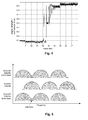
- an exemplary (time) profile of a narrow-band RSSI signal is illustrated during find, acquire, peak-up and track of a satellite signal of interest.
- the x-axis represents time (seconds) and the y-axis represents signal strength in normalized units. From time 0 to approximately 22 seconds, the antenna beam is swept in azimuth while the processor 54 monitors the narrow-band RSSI signal provided by the NbRSSI circuit 30. The sharp peak observed at approximately 21 seconds is caused by the antenna 52 sweeping past the signal of interest.
- the device and method in accordance with the present disclosure allow an antenna pointing and tracking system to operate with a satellite that has only partially populated transponders, meaning satellite transponders which are lightly-loaded, with much of the allocated frequency bandwidth of the transponder unused (not modulated.) Additionally, since systems which rely on a wide-band RSSI signal respond to a broad range of frequencies, these systems tend to have an increased susceptibility to interference from adjacent satellites as compared to the approach in accordance with the present disclosure, which utilizes a much more selective narrow-band RSSI signal.
- the RSSI approach is useful for antenna pointing calibration for both mechanically steered and Electronically Scanned Arrays (ESAs).
- the device and method in accordance with the present disclosure will aid in satellite acquisition, antenna pointing and satellite tracking while stationary or on-the-move (ground mobile, marine, as well as airborne) for antennas across a multiplicity of RF bands.
- the device and method in accordance with the present disclosure are particularly useful for wide beamwidth antennas, which have beamwidths greater than the angular spacing of geo-stationary satellites.
- the device and method in accordance with the present disclosure can avoid interference that comes from the presence of adjacent satellites transmitting in the same RF frequency band.
- NbNSs can also be used to implement a Narrow-band Null Search (NbNS).
- NbNSs is advantageous in that it allows wide beam width antennas (which have beam widths greater than the angular spacing of geo-stationary satellites) to avoid interference that comes from the presence of adjacent satellites transmitting in the same RF band.
- the antenna system 50 tracks on a narrow frequency band on the satellite of interest where no energy is being transmitted as long as both adjacent satellites contain energy in this band.
- the system 50 can first use a wide band filter 36a-36n to make sure it sees the adjacent satellite energy and peak up the antenna pointing using a con-scan approach.
- the system 50 can quickly switch to using a narrower filter 36a-36n, selected so that it is narrower than the null band of the satellite of interest.
- the system 50 then can conical scan the antenna 52 and, using inverse logic based on signal minimization, steer the antenna 52 so that it peaks up this null band and thus avoid being pulled-off by the adjacent satellites.
- the system 50 can switch to the wider filter 36a-36n to make sure the system is not steering away from the entire satellite cluster.
- the device and method in accordance with the present disclosure can also be used to implement a Narrow-band Pseudo-Beacon Receiver (NbPBR) mode, which allows wide beamwidth antennas (which have beamwidths greater than the angular spacing of geo-stationary satellites) avoid interference that comes from the presence of adjacent satellites transmitting in the same RF band.
- NbPBR Narrow-band Pseudo-Beacon Receiver
- the satellite system operator hosts a narrow bandwidth signal on the satellite of interest at a band that is not being used by the two adjacent neighbors (i.e. a pseudo-beacon signal).
- the earth-station antenna system 50 selects a filter 36a-36n with a bandwidth matching the narrow bandwidth signal and uses this signal to find and track the satellite of interest without interference from the adjacent satellites.
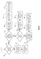
- FIG. 6 a flow diagram 70 illustrating an exemplary hierarchical method for utilizing Narrow-band Receive Signal Strength Indicator, Narrow-band Stop-Band Search, Narrow-band Null Search, and Narrow-band Pseudo-Beacon Receiver using the NbRSSI circuitry and processing in accordance with the present disclosure.
- the methodology illustrated in Fig. 6 may be implemented, for example via the circuit 50 of Fig. 3 .
- the flow diagram includes a number of process blocks arranged in a particular order.
- many alternatives and equivalents to the illustrated steps may exist and such alternatives and equivalents are intended to fall with the scope of the claims appended hereto.
- Alternatives may involve carrying out additional steps or actions not specifically recited and/or shown, carrying out steps or actions in a different order from that recited and/or shown, and/or omitting recited and/or shown steps.
- Alternatives also include carrying out steps or actions concurrently or with partial concurrence.
- the method moves to block 78 where it is determined if the two neighbors both have signals present within the band of interest.
- determination may be made, for example, by performing a scan over the band of interest while using a filter wide enough to cover the band of interest and analyzing data received during the scan. By observing the -3 dB beamwidth of the observed signal map in both azimuth and elevation and comparing it to the known -3 dB beamwidth of our own antenna, the presence of neighbors with signals within the band of interest can be determined.
- a request is made to the satellite service operator to create a narrow null-band on the satellite of interest.
- a request may be transmitted to the satellite service provider to include a null band of a certain width at a particular frequency by negotiating with the hub at the network provider's home frequency where remote users first log in and request a service assignment.
- a null band is a band of frequencies where there is no transmission from the satellite. Then at block 82 the filter 36a-36n having the largest bandwidth that is smaller than the width of the requested null-band is selected.
- the requested width of the null band can be compared to the known bandwidths of the filters 36a-36n, and the filter with the largest bandwidth that is smaller than the width of the requested null-band is selected via multiplexor 38.
- data provided by the RSSI circuit 30 is used in Narrow-band Null Search (NbNS) mode to track the narrow null-band on the satellite of interest.
- NbNS Narrow-band Null Search
- the method moves to block 86 where it is determined if the satellite of interest has signal power at the center of the transponder band.
- the presence of this signal may be determined by performing a scan over a region several times the antenna beamwidth using a filter just smaller than the transponder stop band and centered at the mid-point frequency of the transponder.
- the data collected during the scan can be analyzed to determine if the satellite of interest has a signal at the center of the transponder band - a region where the neighbors have stop bands.
- the method moves to block 88 where the filter 36a-36n having the largest bandwidth that is smaller than the width of the transponder stop band is selected.
- the width of the transponder stop band may be known or otherwise determined. The known bandwidths of the filters 36a-36n then can be compared to the transponder stop bandwidth, and the filter 36a-36n having the largest bandwidth that is smaller than the width of the transponder stop band is selected, for example, via multiplexor 38.
- the RSSI circuit 30 is used in Narrow-band Stop-Band Search (NbSBS) mode to track the signal at the center transponder band on the satellite of interest.
- NbSBS Narrow-band Stop-Band Search
- the method moves to block 92 where the satellite service provided is requested to create a narrow, pseudo-beacon signal at a band unused by both neighbors.
- a suitable band to use can be found by selecting the filter with the second narrowest bandwidth and then sweeping the frequency of the RSSI circuit across the range of frequencies on the satellite transponder while observing the received power. If a frequency band is found which has no power (i.e. the power level is comparable to that of cold sky), then that band is open and can be used for hosting and tracking a pseudo-beacon signal.
- Such requests may be made, for example, by specifying a narrow, pseudo-beacon signal of a particular width and transmitting a request to the satellite service provider. This request is typically made/negotiated with the hub at the network provider's home frequency where remote users first log in and request a service assignment. Then at block 94 the filter 36a-36n having the smallest bandwidth is selected via multiplexor 38. Next, at block 96, the RSSI circuit 30 is used in Narrow-band Pseudo-Beacon Receiver (NbPBR) mode to track the narrow, pseudo-beacon signal on the satellite of interest.
- NbPBR Narrow-band Pseudo-Beacon Receiver
Landscapes
- Engineering & Computer Science (AREA)
- Physics & Mathematics (AREA)
- General Physics & Mathematics (AREA)
- Radar, Positioning & Navigation (AREA)
- Remote Sensing (AREA)
- Computer Networks & Wireless Communication (AREA)
- Signal Processing (AREA)
- Astronomy & Astrophysics (AREA)
- Aviation & Aerospace Engineering (AREA)
- Radio Relay Systems (AREA)
- Variable-Direction Aerials And Aerial Arrays (AREA)
Applications Claiming Priority (1)
| Application Number | Priority Date | Filing Date | Title |
|---|---|---|---|
| US14/302,854 US9479207B2 (en) | 2014-06-12 | 2014-06-12 | Narrowband RSSI technique(s) for the mitigation of adjacent satellite interference |
Publications (2)
| Publication Number | Publication Date |
|---|---|
| EP2955856A1 true EP2955856A1 (fr) | 2015-12-16 |
| EP2955856B1 EP2955856B1 (fr) | 2022-08-03 |
Family
ID=53396251
Family Applications (1)
| Application Number | Title | Priority Date | Filing Date |
|---|---|---|---|
| EP15170496.2A Active EP2955856B1 (fr) | 2014-06-12 | 2015-06-03 | Procede de recherche et de suivi d'un signal d'interet a partir d'un satellite et d'un indicateur rssi a bande etroite |
Country Status (4)
| Country | Link |
|---|---|
| US (1) | US9479207B2 (fr) |
| EP (1) | EP2955856B1 (fr) |
| CA (1) | CA2894050C (fr) |
| ES (1) | ES2928701T3 (fr) |
Cited By (2)
| Publication number | Priority date | Publication date | Assignee | Title |
|---|---|---|---|---|
| CN112165350A (zh) * | 2020-08-24 | 2021-01-01 | 中国电子科技集团公司第二十九研究所 | 一种面向中低轨卫星下行相控阵捷变波束控制装置及方法 |
| RU2796219C1 (ru) * | 2022-10-31 | 2023-05-18 | Акционерное общество "Центральный научно-исследовательский радиотехнический институт имени академика А.И. Берга" | Устройство определения пеленгационных параметров узкополосных радиосигналов |
Families Citing this family (5)
| Publication number | Priority date | Publication date | Assignee | Title |
|---|---|---|---|---|
| FR3043513B1 (fr) * | 2015-11-10 | 2017-12-22 | Thales Sa | Procede de caracterisation des performances d'une charge utile d'un satellite en orbite et systeme de test iot associe |
| US10277308B1 (en) | 2016-09-22 | 2019-04-30 | Viasat, Inc. | Methods and systems of adaptive antenna pointing for mitigating interference with a nearby satellite |
| US10840998B2 (en) * | 2017-06-21 | 2020-11-17 | Blue Digs LLC | Broadband satellite terminal |
| US10871575B2 (en) | 2018-10-26 | 2020-12-22 | Viasat, Inc. | Multi-mode frequency compensation in mobile terminals |
| US10749557B1 (en) | 2019-07-12 | 2020-08-18 | Bae Systems Information And Electronic Systems Integration Inc. | Adaptive spur processing |
Citations (3)
| Publication number | Priority date | Publication date | Assignee | Title |
|---|---|---|---|---|
| US3309699A (en) * | 1964-05-21 | 1967-03-14 | Hughes Aircraft Co | Tracking system for communication satellites |
| US20020097184A1 (en) * | 2000-02-17 | 2002-07-25 | Mayersak Joseph R. | Location of radio frequency emitting targets |
| US20030078040A1 (en) * | 1998-06-26 | 2003-04-24 | William W. Mayfield | Communication system employing reuse of satellite spectrum for terrestrial communication |
Family Cites Families (3)
| Publication number | Priority date | Publication date | Assignee | Title |
|---|---|---|---|---|
| CN1659811A (zh) * | 2002-06-07 | 2005-08-24 | 皇家飞利浦电子股份有限公司 | 接收机信号强度指示 |
| WO2008077036A2 (fr) * | 2006-12-19 | 2008-06-26 | Massachusetts Institute Of Technology | Architectures pour radio universelle ou logicielle |
| US9088328B2 (en) * | 2011-05-16 | 2015-07-21 | Intel Mobile Communications GmbH | Receiver of a mobile communication device |
-
2014
- 2014-06-12 US US14/302,854 patent/US9479207B2/en active Active
-
2015
- 2015-06-03 EP EP15170496.2A patent/EP2955856B1/fr active Active
- 2015-06-03 ES ES15170496T patent/ES2928701T3/es active Active
- 2015-06-10 CA CA2894050A patent/CA2894050C/fr active Active
Patent Citations (3)
| Publication number | Priority date | Publication date | Assignee | Title |
|---|---|---|---|---|
| US3309699A (en) * | 1964-05-21 | 1967-03-14 | Hughes Aircraft Co | Tracking system for communication satellites |
| US20030078040A1 (en) * | 1998-06-26 | 2003-04-24 | William W. Mayfield | Communication system employing reuse of satellite spectrum for terrestrial communication |
| US20020097184A1 (en) * | 2000-02-17 | 2002-07-25 | Mayersak Joseph R. | Location of radio frequency emitting targets |
Cited By (3)
| Publication number | Priority date | Publication date | Assignee | Title |
|---|---|---|---|---|
| CN112165350A (zh) * | 2020-08-24 | 2021-01-01 | 中国电子科技集团公司第二十九研究所 | 一种面向中低轨卫星下行相控阵捷变波束控制装置及方法 |
| CN112165350B (zh) * | 2020-08-24 | 2022-04-12 | 中国电子科技集团公司第二十九研究所 | 一种面向中低轨卫星下行相控阵捷变波束控制装置及方法 |
| RU2796219C1 (ru) * | 2022-10-31 | 2023-05-18 | Акционерное общество "Центральный научно-исследовательский радиотехнический институт имени академика А.И. Берга" | Устройство определения пеленгационных параметров узкополосных радиосигналов |
Also Published As
| Publication number | Publication date |
|---|---|
| CA2894050C (fr) | 2021-10-26 |
| US9479207B2 (en) | 2016-10-25 |
| US20150365116A1 (en) | 2015-12-17 |
| CA2894050A1 (fr) | 2015-12-12 |
| ES2928701T3 (es) | 2022-11-22 |
| EP2955856B1 (fr) | 2022-08-03 |
Similar Documents
| Publication | Publication Date | Title |
|---|---|---|
| EP2955856B1 (fr) | Procede de recherche et de suivi d'un signal d'interet a partir d'un satellite et d'un indicateur rssi a bande etroite | |
| US9673888B2 (en) | Acquiring LEO satellites without compass | |
| Blázquez-García et al. | Experimental comparison of Starlink and OneWeb signals for passive radar | |
| EP3334060B1 (fr) | Méthode d'acquisition de satellite accélérée par elargissement du champ de vue d'une antenne réseau à commande de phase reconfigurable. | |
| AU2013354340B2 (en) | Apparatuses, systems and methods for obtaining information about electromagnetic energy emitted from the earth, such as for locating an interference source on earth | |
| US10684347B2 (en) | Systems and methods for measuring terrestrial spectrum from space | |
| Gomez-Del-Hoyo et al. | The STARLINK-based passive radar: preliminary study and first illuminator signal measurements | |
| US11472578B2 (en) | Method and system for estimating the direction of a satellite in the transfer phase from an initial orbit to a mission orbit | |
| KR101289058B1 (ko) | 멀티 위성 수신용 자동 포지셔닝 안테나 시스템 및 위성 추적 방법 | |
| Blazquez-Garcia et al. | Experimental acquisition of Starlink satellite transmissions for passive radar applications | |
| Gomez-Del-Hoyo et al. | Digital steerable antenna control system for IoO tracking in Starlink based Passive Radar applications | |
| Takahashi et al. | Four-year result of external calibration for Precipitation Radar (PR) of the Tropical Rainfall Measuring Mission (TRMM) satellite | |
| US12607756B2 (en) | Ground data transmission and fan out for a terminal of a satellite communication system | |
| Seidel et al. | High resolution DVB-S based passive radar for ISAR imaging and drone detection | |
| Zuo | Bistatic synthetic aperture radar using GNSS as transmitters of opportunity | |
| US7230569B1 (en) | Search algorithm for phased array antenna | |
| Machado et al. | The Ka-and Q-band AlphaSat ground station in Vigo | |
| US12306288B2 (en) | Radio system with multiple antenna arrays and adaptive waveforms | |
| Braun et al. | Daily monitoring of the mediterranean sea by Geosynchronous SAR | |
| US20250374253A1 (en) | Satellite communication system | |
| US20250370143A1 (en) | Ground data receipt and fan out for a satellite communication system | |
| US20260019213A1 (en) | Low data rate service for a terminal of a satellite communication system | |
| US20250373325A1 (en) | Antenna beam setup for a satellite communication system | |
| US20250374254A1 (en) | Waveform and data characteristics for a terminal of a satellite communication system | |
| Hahn | Spatial and Polarization Domain-Based GNSS Processing for Multipath Mitigation using a Dual-Polarized Antenna Array |
Legal Events
| Date | Code | Title | Description |
|---|---|---|---|
| PUAI | Public reference made under article 153(3) epc to a published international application that has entered the european phase |
Free format text: ORIGINAL CODE: 0009012 |
|
| AK | Designated contracting states |
Kind code of ref document: A1 Designated state(s): AL AT BE BG CH CY CZ DE DK EE ES FI FR GB GR HR HU IE IS IT LI LT LU LV MC MK MT NL NO PL PT RO RS SE SI SK SM TR |
|
| AX | Request for extension of the european patent |
Extension state: BA ME |
|
| 17P | Request for examination filed |
Effective date: 20160616 |
|
| RBV | Designated contracting states (corrected) |
Designated state(s): AL AT BE BG CH CY CZ DE DK EE ES FI FR GB GR HR HU IE IS IT LI LT LU LV MC MK MT NL NO PL PT RO RS SE SI SK SM TR |
|
| STAA | Information on the status of an ep patent application or granted ep patent |
Free format text: STATUS: EXAMINATION IS IN PROGRESS |
|
| 17Q | First examination report despatched |
Effective date: 20180717 |
|
| REG | Reference to a national code |
Ref country code: DE Ref legal event code: R079 Ref document number: 602015080116 Country of ref document: DE Free format text: PREVIOUS MAIN CLASS: H04B0001260000 Ipc: G01S0003040000 |
|
| GRAP | Despatch of communication of intention to grant a patent |
Free format text: ORIGINAL CODE: EPIDOSNIGR1 |
|
| STAA | Information on the status of an ep patent application or granted ep patent |
Free format text: STATUS: GRANT OF PATENT IS INTENDED |
|
| RIC1 | Information provided on ipc code assigned before grant |
Ipc: H04B 1/26 20060101ALI20220218BHEP Ipc: H04B 7/185 20060101ALI20220218BHEP Ipc: G01S 3/42 20060101ALI20220218BHEP Ipc: G01S 3/38 20060101ALI20220218BHEP Ipc: G01S 3/04 20060101AFI20220218BHEP |
|
| INTG | Intention to grant announced |
Effective date: 20220309 |
|
| GRAS | Grant fee paid |
Free format text: ORIGINAL CODE: EPIDOSNIGR3 |
|
| GRAA | (expected) grant |
Free format text: ORIGINAL CODE: 0009210 |
|
| STAA | Information on the status of an ep patent application or granted ep patent |
Free format text: STATUS: THE PATENT HAS BEEN GRANTED |
|
| AK | Designated contracting states |
Kind code of ref document: B1 Designated state(s): AL AT BE BG CH CY CZ DE DK EE ES FI FR GB GR HR HU IE IS IT LI LT LU LV MC MK MT NL NO PL PT RO RS SE SI SK SM TR |
|
| REG | Reference to a national code |
Ref country code: AT Ref legal event code: REF Ref document number: 1509173 Country of ref document: AT Kind code of ref document: T Effective date: 20220815 Ref country code: CH Ref legal event code: EP |
|
| REG | Reference to a national code |
Ref country code: DE Ref legal event code: R096 Ref document number: 602015080116 Country of ref document: DE |
|
| REG | Reference to a national code |
Ref country code: IE Ref legal event code: FG4D |
|
| REG | Reference to a national code |
Ref country code: ES Ref legal event code: FG2A Ref document number: 2928701 Country of ref document: ES Kind code of ref document: T3 Effective date: 20221122 |
|
| REG | Reference to a national code |
Ref country code: LT Ref legal event code: MG9D |
|
| REG | Reference to a national code |
Ref country code: NL Ref legal event code: MP Effective date: 20220803 |
|
| PG25 | Lapsed in a contracting state [announced via postgrant information from national office to epo] |
Ref country code: SE Free format text: LAPSE BECAUSE OF FAILURE TO SUBMIT A TRANSLATION OF THE DESCRIPTION OR TO PAY THE FEE WITHIN THE PRESCRIBED TIME-LIMIT Effective date: 20220803 Ref country code: RS Free format text: LAPSE BECAUSE OF FAILURE TO SUBMIT A TRANSLATION OF THE DESCRIPTION OR TO PAY THE FEE WITHIN THE PRESCRIBED TIME-LIMIT Effective date: 20220803 Ref country code: PT Free format text: LAPSE BECAUSE OF FAILURE TO SUBMIT A TRANSLATION OF THE DESCRIPTION OR TO PAY THE FEE WITHIN THE PRESCRIBED TIME-LIMIT Effective date: 20221205 Ref country code: NO Free format text: LAPSE BECAUSE OF FAILURE TO SUBMIT A TRANSLATION OF THE DESCRIPTION OR TO PAY THE FEE WITHIN THE PRESCRIBED TIME-LIMIT Effective date: 20221103 Ref country code: NL Free format text: LAPSE BECAUSE OF FAILURE TO SUBMIT A TRANSLATION OF THE DESCRIPTION OR TO PAY THE FEE WITHIN THE PRESCRIBED TIME-LIMIT Effective date: 20220803 Ref country code: LV Free format text: LAPSE BECAUSE OF FAILURE TO SUBMIT A TRANSLATION OF THE DESCRIPTION OR TO PAY THE FEE WITHIN THE PRESCRIBED TIME-LIMIT Effective date: 20220803 Ref country code: LT Free format text: LAPSE BECAUSE OF FAILURE TO SUBMIT A TRANSLATION OF THE DESCRIPTION OR TO PAY THE FEE WITHIN THE PRESCRIBED TIME-LIMIT Effective date: 20220803 Ref country code: FI Free format text: LAPSE BECAUSE OF FAILURE TO SUBMIT A TRANSLATION OF THE DESCRIPTION OR TO PAY THE FEE WITHIN THE PRESCRIBED TIME-LIMIT Effective date: 20220803 |
|
| REG | Reference to a national code |
Ref country code: AT Ref legal event code: MK05 Ref document number: 1509173 Country of ref document: AT Kind code of ref document: T Effective date: 20220803 |
|
| PG25 | Lapsed in a contracting state [announced via postgrant information from national office to epo] |
Ref country code: PL Free format text: LAPSE BECAUSE OF FAILURE TO SUBMIT A TRANSLATION OF THE DESCRIPTION OR TO PAY THE FEE WITHIN THE PRESCRIBED TIME-LIMIT Effective date: 20220803 Ref country code: IS Free format text: LAPSE BECAUSE OF FAILURE TO SUBMIT A TRANSLATION OF THE DESCRIPTION OR TO PAY THE FEE WITHIN THE PRESCRIBED TIME-LIMIT Effective date: 20221203 Ref country code: HR Free format text: LAPSE BECAUSE OF FAILURE TO SUBMIT A TRANSLATION OF THE DESCRIPTION OR TO PAY THE FEE WITHIN THE PRESCRIBED TIME-LIMIT Effective date: 20220803 Ref country code: GR Free format text: LAPSE BECAUSE OF FAILURE TO SUBMIT A TRANSLATION OF THE DESCRIPTION OR TO PAY THE FEE WITHIN THE PRESCRIBED TIME-LIMIT Effective date: 20221104 |
|
| PG25 | Lapsed in a contracting state [announced via postgrant information from national office to epo] |
Ref country code: SM Free format text: LAPSE BECAUSE OF FAILURE TO SUBMIT A TRANSLATION OF THE DESCRIPTION OR TO PAY THE FEE WITHIN THE PRESCRIBED TIME-LIMIT Effective date: 20220803 Ref country code: RO Free format text: LAPSE BECAUSE OF FAILURE TO SUBMIT A TRANSLATION OF THE DESCRIPTION OR TO PAY THE FEE WITHIN THE PRESCRIBED TIME-LIMIT Effective date: 20220803 Ref country code: DK Free format text: LAPSE BECAUSE OF FAILURE TO SUBMIT A TRANSLATION OF THE DESCRIPTION OR TO PAY THE FEE WITHIN THE PRESCRIBED TIME-LIMIT Effective date: 20220803 Ref country code: CZ Free format text: LAPSE BECAUSE OF FAILURE TO SUBMIT A TRANSLATION OF THE DESCRIPTION OR TO PAY THE FEE WITHIN THE PRESCRIBED TIME-LIMIT Effective date: 20220803 Ref country code: AT Free format text: LAPSE BECAUSE OF FAILURE TO SUBMIT A TRANSLATION OF THE DESCRIPTION OR TO PAY THE FEE WITHIN THE PRESCRIBED TIME-LIMIT Effective date: 20220803 |
|
| REG | Reference to a national code |
Ref country code: DE Ref legal event code: R097 Ref document number: 602015080116 Country of ref document: DE |
|
| PG25 | Lapsed in a contracting state [announced via postgrant information from national office to epo] |
Ref country code: SK Free format text: LAPSE BECAUSE OF FAILURE TO SUBMIT A TRANSLATION OF THE DESCRIPTION OR TO PAY THE FEE WITHIN THE PRESCRIBED TIME-LIMIT Effective date: 20220803 Ref country code: EE Free format text: LAPSE BECAUSE OF FAILURE TO SUBMIT A TRANSLATION OF THE DESCRIPTION OR TO PAY THE FEE WITHIN THE PRESCRIBED TIME-LIMIT Effective date: 20220803 |
|
| PLBE | No opposition filed within time limit |
Free format text: ORIGINAL CODE: 0009261 |
|
| STAA | Information on the status of an ep patent application or granted ep patent |
Free format text: STATUS: NO OPPOSITION FILED WITHIN TIME LIMIT |
|
| P01 | Opt-out of the competence of the unified patent court (upc) registered |
Effective date: 20230523 |
|
| PG25 | Lapsed in a contracting state [announced via postgrant information from national office to epo] |
Ref country code: AL Free format text: LAPSE BECAUSE OF FAILURE TO SUBMIT A TRANSLATION OF THE DESCRIPTION OR TO PAY THE FEE WITHIN THE PRESCRIBED TIME-LIMIT Effective date: 20220803 |
|
| 26N | No opposition filed |
Effective date: 20230504 |
|
| REG | Reference to a national code |
Ref country code: DE Ref legal event code: R082 Ref document number: 602015080116 Country of ref document: DE Representative=s name: MEISSNER BOLTE PATENTANWAELTE RECHTSANWAELTE P, DE |
|
| PG25 | Lapsed in a contracting state [announced via postgrant information from national office to epo] |
Ref country code: SI Free format text: LAPSE BECAUSE OF FAILURE TO SUBMIT A TRANSLATION OF THE DESCRIPTION OR TO PAY THE FEE WITHIN THE PRESCRIBED TIME-LIMIT Effective date: 20220803 |
|
| PG25 | Lapsed in a contracting state [announced via postgrant information from national office to epo] |
Ref country code: MC Free format text: LAPSE BECAUSE OF FAILURE TO SUBMIT A TRANSLATION OF THE DESCRIPTION OR TO PAY THE FEE WITHIN THE PRESCRIBED TIME-LIMIT Effective date: 20220803 |
|
| PG25 | Lapsed in a contracting state [announced via postgrant information from national office to epo] |
Ref country code: MC Free format text: LAPSE BECAUSE OF FAILURE TO SUBMIT A TRANSLATION OF THE DESCRIPTION OR TO PAY THE FEE WITHIN THE PRESCRIBED TIME-LIMIT Effective date: 20220803 |
|
| REG | Reference to a national code |
Ref country code: CH Ref legal event code: PL |
|
| REG | Reference to a national code |
Ref country code: BE Ref legal event code: MM Effective date: 20230630 |
|
| PG25 | Lapsed in a contracting state [announced via postgrant information from national office to epo] |
Ref country code: LU Free format text: LAPSE BECAUSE OF NON-PAYMENT OF DUE FEES Effective date: 20230603 |
|
| REG | Reference to a national code |
Ref country code: IE Ref legal event code: MM4A |
|
| PG25 | Lapsed in a contracting state [announced via postgrant information from national office to epo] |
Ref country code: LU Free format text: LAPSE BECAUSE OF NON-PAYMENT OF DUE FEES Effective date: 20230603 |
|
| PG25 | Lapsed in a contracting state [announced via postgrant information from national office to epo] |
Ref country code: IE Free format text: LAPSE BECAUSE OF NON-PAYMENT OF DUE FEES Effective date: 20230603 |
|
| PG25 | Lapsed in a contracting state [announced via postgrant information from national office to epo] |
Ref country code: IE Free format text: LAPSE BECAUSE OF NON-PAYMENT OF DUE FEES Effective date: 20230603 Ref country code: CH Free format text: LAPSE BECAUSE OF NON-PAYMENT OF DUE FEES Effective date: 20230630 |
|
| PG25 | Lapsed in a contracting state [announced via postgrant information from national office to epo] |
Ref country code: BE Free format text: LAPSE BECAUSE OF NON-PAYMENT OF DUE FEES Effective date: 20230630 |
|
| PG25 | Lapsed in a contracting state [announced via postgrant information from national office to epo] |
Ref country code: BG Free format text: LAPSE BECAUSE OF FAILURE TO SUBMIT A TRANSLATION OF THE DESCRIPTION OR TO PAY THE FEE WITHIN THE PRESCRIBED TIME-LIMIT Effective date: 20220803 |
|
| PG25 | Lapsed in a contracting state [announced via postgrant information from national office to epo] |
Ref country code: BG Free format text: LAPSE BECAUSE OF FAILURE TO SUBMIT A TRANSLATION OF THE DESCRIPTION OR TO PAY THE FEE WITHIN THE PRESCRIBED TIME-LIMIT Effective date: 20220803 |
|
| PGFP | Annual fee paid to national office [announced via postgrant information from national office to epo] |
Ref country code: DE Payment date: 20250520 Year of fee payment: 11 |
|
| PGFP | Annual fee paid to national office [announced via postgrant information from national office to epo] |
Ref country code: GB Payment date: 20250520 Year of fee payment: 11 |
|
| PGFP | Annual fee paid to national office [announced via postgrant information from national office to epo] |
Ref country code: IT Payment date: 20250520 Year of fee payment: 11 |
|
| PGFP | Annual fee paid to national office [announced via postgrant information from national office to epo] |
Ref country code: FR Payment date: 20250520 Year of fee payment: 11 |
|
| PG25 | Lapsed in a contracting state [announced via postgrant information from national office to epo] |
Ref country code: CY Free format text: LAPSE BECAUSE OF FAILURE TO SUBMIT A TRANSLATION OF THE DESCRIPTION OR TO PAY THE FEE WITHIN THE PRESCRIBED TIME-LIMIT; INVALID AB INITIO Effective date: 20150603 |
|
| PG25 | Lapsed in a contracting state [announced via postgrant information from national office to epo] |
Ref country code: HU Free format text: LAPSE BECAUSE OF FAILURE TO SUBMIT A TRANSLATION OF THE DESCRIPTION OR TO PAY THE FEE WITHIN THE PRESCRIBED TIME-LIMIT; INVALID AB INITIO Effective date: 20150603 |
|
| PGFP | Annual fee paid to national office [announced via postgrant information from national office to epo] |
Ref country code: ES Payment date: 20250701 Year of fee payment: 11 |
|
| PG25 | Lapsed in a contracting state [announced via postgrant information from national office to epo] |
Ref country code: TR Free format text: LAPSE BECAUSE OF FAILURE TO SUBMIT A TRANSLATION OF THE DESCRIPTION OR TO PAY THE FEE WITHIN THE PRESCRIBED TIME-LIMIT Effective date: 20220803 |