EP2955968A2 - Dispositif de gestion d'attribution de sous-trame à un dispositif mtc - Google Patents
Dispositif de gestion d'attribution de sous-trame à un dispositif mtc Download PDFInfo
- Publication number
- EP2955968A2 EP2955968A2 EP15171778.2A EP15171778A EP2955968A2 EP 2955968 A2 EP2955968 A2 EP 2955968A2 EP 15171778 A EP15171778 A EP 15171778A EP 2955968 A2 EP2955968 A2 EP 2955968A2
- Authority
- EP
- European Patent Office
- Prior art keywords
- subframe
- subframes
- mtc
- communication device
- mtc device
- Prior art date
- Legal status (The legal status is an assumption and is not a legal conclusion. Google has not performed a legal analysis and makes no representation as to the accuracy of the status listed.)
- Withdrawn
Links
- 238000004891 communication Methods 0.000 claims abstract description 59
- 238000012545 processing Methods 0.000 claims abstract description 15
- 230000005540 biological transmission Effects 0.000 claims description 20
- 230000011664 signaling Effects 0.000 claims description 10
- 238000000034 method Methods 0.000 description 51
- 230000008569 process Effects 0.000 description 43
- 238000010586 diagram Methods 0.000 description 14
- 230000006870 function Effects 0.000 description 9
- 238000013500 data storage Methods 0.000 description 3
- 230000001960 triggered effect Effects 0.000 description 3
- 230000002776 aggregation Effects 0.000 description 2
- 238000004220 aggregation Methods 0.000 description 2
- 230000004075 alteration Effects 0.000 description 2
- 239000000969 carrier Substances 0.000 description 2
- 230000006872 improvement Effects 0.000 description 2
- 230000007774 longterm Effects 0.000 description 2
- 238000007726 management method Methods 0.000 description 2
- 238000012986 modification Methods 0.000 description 2
- 230000004048 modification Effects 0.000 description 2
- 230000003287 optical effect Effects 0.000 description 2
- 238000013468 resource allocation Methods 0.000 description 2
- 238000004590 computer program Methods 0.000 description 1
- 230000002708 enhancing effect Effects 0.000 description 1
- 238000013507 mapping Methods 0.000 description 1
- 238000005457 optimization Methods 0.000 description 1
- 230000000717 retained effect Effects 0.000 description 1
Images







Classifications
-
- H—ELECTRICITY
- H04—ELECTRIC COMMUNICATION TECHNIQUE
- H04L—TRANSMISSION OF DIGITAL INFORMATION, e.g. TELEGRAPHIC COMMUNICATION
- H04L5/00—Arrangements affording multiple use of the transmission path
- H04L5/003—Arrangements for allocating sub-channels of the transmission path
- H04L5/0053—Allocation of signalling, i.e. of overhead other than pilot signals
-
- H—ELECTRICITY
- H04—ELECTRIC COMMUNICATION TECHNIQUE
- H04L—TRANSMISSION OF DIGITAL INFORMATION, e.g. TELEGRAPHIC COMMUNICATION
- H04L5/00—Arrangements affording multiple use of the transmission path
- H04L5/0091—Signalling for the administration of the divided path, e.g. signalling of configuration information
- H04L5/0092—Indication of how the channel is divided
-
- H—ELECTRICITY
- H04—ELECTRIC COMMUNICATION TECHNIQUE
- H04W—WIRELESS COMMUNICATION NETWORKS
- H04W4/00—Services specially adapted for wireless communication networks; Facilities therefor
- H04W4/70—Services for machine-to-machine communication [M2M] or machine type communication [MTC]
-
- H—ELECTRICITY
- H04—ELECTRIC COMMUNICATION TECHNIQUE
- H04W—WIRELESS COMMUNICATION NETWORKS
- H04W72/00—Local resource management
- H04W72/20—Control channels or signalling for resource management
- H04W72/23—Control channels or signalling for resource management in the downlink direction of a wireless link, i.e. towards a terminal
-
- H—ELECTRICITY
- H04—ELECTRIC COMMUNICATION TECHNIQUE
- H04W—WIRELESS COMMUNICATION NETWORKS
- H04W72/00—Local resource management
- H04W72/04—Wireless resource allocation
- H04W72/044—Wireless resource allocation based on the type of the allocated resource
- H04W72/0446—Resources in time domain, e.g. slots or frames
Definitions
- the present invention is related to a communication device used in a wireless communication system, and more particularly, to a communication device of indicating a subframe allocation in a wireless communication system.
- LTE long-term evolution
- 3GPP 3rd Generation Partnership Project
- 3GPP Rel-8 3rd Generation Partnership Project
- 3GPP Rel-9 3rd Generation Partnership Project
- UMTS universal mobile telecommunications system
- the LTE system includes a new radio interface and a new radio network architecture that provides a high data rate, low latency, packet optimization, and improved system capacity and coverage.
- a radio access network known as an evolved universal terrestrial radio access network (E-UTRAN) includes multiple evolved Node-Bs (eNBs) for communicating with multiple user equipments (UEs), and for communicating with a core network including a mobility management entity (MME), a serving gateway, etc., for Non-Access Stratum (NAS) control.
- E-UTRAN evolved universal terrestrial radio access network
- eNBs evolved Node-Bs
- MME mobility management entity
- serving gateway etc.
- NAS Non-Access Stratum
- LTE-advanced (LTE-A) system is an evolution of the LTE system.
- the LTE-A system targets faster switching between power states, improves performance at the coverage edge of an eNB, and includes advanced techniques, such as carrier aggregation (CA), coordinated multipoint (CoMP) transmission/reception, uplink multiple-input multiple-output (UL-MIMO), etc.
- CA carrier aggregation
- CoMP coordinated multipoint
- UL-MIMO uplink multiple-input multiple-output
- the UE and the eNB must support standards developed for the LTE-A system, such as the 3GPP Rel-10 standard or later versions.
- a machine type communication (MTC) device which can automatically perform predefined jobs and report corresponding results to other devices, a server, a NB or an eNB can be used in various areas, such as security, tracking and tracing, payment, healthcare, metering, etc. Further, the MTC device preferably reports the corresponding results via a wireless link such that limitation caused by environment can be removed. However, the wireless link used by the MTC device is needed to be established, and radio resource required by the wireless link is needed to be allocated (i.e., assigned). Reuse of existing infrastructures and wireless communication systems become a viable choose for operation of the MTC device. Therefore, the UMTS, the LTE system and the LTE-A system, etc., developed by the 3GPP which are widely deployed are suitable for the operation of the MTC device.
- Coverage improvement is a desirable feature for MTC devices in deep indoor environment.
- a promising technique for achieving the coverage improvement is repetition of transmissions. Proper scheduling is necessary for realizing the repetition of transmissions.
- a data channel is scheduled by a control channel in the same subframe. Considering repetition of data transmissions, since the number of repetitions may be huge and the repetition may also be applied to the control channel, the data channel may not be able to be scheduled by the control channel in the same subframe according to the legacy rule, e.g., continuous repetition of transmissions may block transmissions for non-MTC devices. In other words, more flexibility on the scheduling timing is necessary.
- a control channel only schedules a data channel in one subframe, with the emergence of repetition, an extension of downlink (DL) control information (DCI) is necessary.
- DCI downlink control information
- a cross-subframe scheduling may be suitable for the MTC transmission.
- a well-structured subframe allocation is needed to solve the cross-subframe scheduling and the repetition of transmissions.
- the present invention therefore provides a communication device for indicating a subframe allocation to solve the abovementioned problem.
- a communication device for indicating a subframe allocation to a machine type communication (MTC) device comprises a storage unit for storing instructions and a processing means coupled to the storage unit.
- the processing means is configured to execute the instructions stored in the storage unit.
- the instructions comprise selecting at least one subframe group from a plurality of subframe groups; determining a plurality of subframe allocation bits corresponding to the least one subframe group; and transmitting the plurality of subframe allocation bits to the MTC device, to indicate the at least one subframe group to the MTC device.
- a communication device for indicating a subframe allocation to a machine type communication (MTC) device comprises a storage unit for storing instructions and a processing means coupled to the storage unit.
- the processing means is configured to execute the instructions stored in the storage unit.
- the instructions comprise selecting a plurality of subframes from potential scheduled subframes; determining a starting subframe of the plurality of subframes and a length of the plurality of subframes; and transmitting an indication corresponding to the starting subframe and the length of the plurality of subframes to the MTC device, to indicate the plurality of subframes to the MTC device.
- a communication device for indicating a subframe allocation to a machine type communication (MTC) device comprises a storage unit for storing instructions and a processing means coupled to the storage unit.
- the processing means is configured to execute the instructions stored in the storage unit.
- the instructions comprise selecting at least one subframe group from potential scheduled subframes; determining at least one starting subframe of the at least one subframe group and at least one ending subframe of the at least one subframe group; and transmitting a combinatorial index corresponding to the at least one starting subframe and the length to the MTC device, to indicate the at least one subframe group to the MTC device.
- Fig. 1 is a schematic diagram of a wireless communication system 10 according to an example of the present invention.
- the wireless communication system 10 is briefly composed of a network and a plurality of communication devices.
- the wireless communication system 10 may support a time-division duplexing (TDD) mode, a frequency-division duplexing (FDD) mode or a TDD-FDD joint operation mode. That is, the network and a communication device may communicate with each other via FDD carrier (s) and/or TDD carrier (s) .
- the wireless communication system 10 may support a carrier aggregation (CA).
- TDD time-division duplexing
- FDD frequency-division duplexing
- CA carrier aggregation
- the network and a communication device may communicate with each other via multiple cells (e.g., multiple carriers) including a primary cell (e.g., primary component carrier (PCC)) and one or more secondary cells (e.g., secondary component carriers (SCCs)).
- the abovementioned cells may be operated in the same or different duplexing modes.
- each cell may be a FDD cell (or TDD cell), when the cells are operated in the same duplexing mode.
- TDD-FDD joint operation when the cells are operated in different duplexing modes (e.g. TDD-FDD joint operation).
- the primary cell may be operated on a TDD carrier, while a secondary cell may be operated on a FDD carrier.
- the primary cell may be operated on the FDD carrier, while the secondary cell may be operated on the TDD carrier.
- the network and the communication devices are simply utilized for illustrating the structure of the wireless communication system 10.
- the network may be a universal terrestrial radio access network (UTRAN) comprising a plurality of Node-Bs (NBs) in a universal mobile telecommunications system (UMTS).
- UTRAN universal terrestrial radio access network
- NBs Node-Bs
- UMTS universal mobile telecommunications system
- the network may be an evolved UTRAN (E-UTRAN) including at least one evolved NB (eNB) and/or at least one relay in a long term evolution (LTE) system, a LTE-Advanced (LTE-A) system or an evolution of the LTE-A system.
- LTE long term evolution
- LTE-A LTE-Advanced
- the network may also include both the UTRAN/E-UTRAN and a core network, wherein the core network may include network entities such as Mobility Management Entity (MME), Serving Gateway (S-GW), Packet Data Network (PDN) Gateway (P-GW), Self-Organizing Networks (SON) server and/or Radio Network Controller (RNC), etc.
- MME Mobility Management Entity
- S-GW Serving Gateway
- PDN Packet Data Network
- P-GW Packet Data Network Gateway
- SON Self-Organizing Networks
- RNC Radio Network Controller
- a communication device may be a user equipment (UE), a low cost device (e.g., machine type communication (MTC) device), a device-to-device (D2D) device, a mobile phone, a laptop, a tablet computer, an electronic book, a portable computer system, or combination thereof.
- the network and the communication device can be seen as a transmitter or a receiver according to direction (i.e., transmission direction), e.g., for an uplink (UL), the communication device is the transmitter and the network is the receiver, and for a downlink (DL), the network is the transmitter and the communication device is the receiver.
- direction i.e., transmission direction
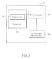
- Fig. 2 is a schematic diagram of a communication device 20 according to an example of the present invention.
- the communication device 20 may be used for realizing a communication device and/or the network shown in Fig. 1 , but is not limited herein.
- the communication device 20 may include a processing means 200 such as a microprocessor or Application Specific Integrated Circuit (ASIC), a storage unit 210 and a communication interfacing unit 220.
- the storage unit 210 may be any data storage device that may store a program code 214, accessed and executed by the processing means 200.
- Examples of the storage unit 210 include but are not limited to a subscriber identity module (SIM), read-only memory (ROM), flash memory, random-access memory (RAM), Compact Disc Read-Only Memory (CD-ROM), digital versatile disc-ROM (DVD-ROM), Blu-ray Disc-ROM (BD-ROM), magnetic tape, hard disk, optical data storage device, non-volatile storage unit, non-transitory computer-readable medium (e.g., tangible media), etc.
- SIM subscriber identity module
- ROM read-only memory
- flash memory random-access memory
- RAM Compact Disc Read-Only Memory
- DVD-ROM digital versatile disc-ROM
- BD-ROM Blu-ray Disc-ROM
- Fig. 3 is a flowchart of a process 30 according to an example of the present invention.
- the process 30 may be utilized in the network (e.g., an eNB) shown in Fig. 1 , to indicate a subframe allocation to a MTC device.
- the process 30 may be compiled into the program code 214 and includes the following steps:
- the network selects at least one subframe group from a plurality of subframe groups, and determines a plurality of subframe allocation bits corresponding to the least one subframe group. Then, the network transmits the plurality of subframe allocation bits to the MTC device, to indicate the at least one subframe group to the MTC device. That is, the at least one subframe group is allocated to the MTC device by using the subframe allocation bits, wherein a subframe group may include one or more subframes. Thus, the subframe(s) is allocated to the MTC device efficiently.
- a size of each of the plurality of subframe groups may be a first fixed value (e.g., predetermined value), may be a first function of a repetition level of MTC transmission, may be a first function of a total number of potential scheduled subframes, may be indicated by a first DL control information (DCI), or may be configured by a first radio resource control (RRC) signalling. That is, the number of subframes in a subframe group may be determined according any of the above methods, and is not limited herein.
- a first fixed value e.g., predetermined value
- DCI DL control information
- RRC radio resource control
- the total number of potential scheduled subframes may be a second fixed value (e.g., predetermined value), may be a second function of the repetition level of MTC transmission, may be a second function of the total number of potential scheduled subframes, may be indicated by a second DCI, or may be configured by a second RRC signalling. That is, the total number of subframes which may be available for the MTC may be determined according any of the above methods, and is not limited herein. It should be noted that the first DCI and the second DCI may be the same DCI, and the first RRC signalling and the second RRC signalling may be the same signalling.
- the plurality of subframe allocation bits in the process 30 may include a bitmap. That is, the subframe allocation bits may simply be a bitmap wherein each bit in the bitmap maps to a corresponding subframe group. For example, a bit "1" means that the corresponding subframe group is allocated, while a bit "0" means that the corresponding subframe group is not allocated
- each of the at least one subframe group may include consecutive subframes. That is, a subframe group may include (e.g., only) consecutive subframes.
- the plurality of subframe allocation bits may be transmitted via in a DCI to the MTC device.
- the at least one subframe group may be allocated for a physical DL shared channel (PDSCH) or a physical UL shared channel (PUSCH) . That is, the MTC device may receive the PDSCH or transmit the PUSCH via the at least one subframe group indicated by the network.
- PDSCH physical DL shared channel
- PUSCH physical UL shared channel
- the bitmap may be of a size N SG bits, where one bitmap bit per subframe group such that each subframe group is addressable. Starting at a first subframe, the subframe groups may be indexed in the order of increasing time and non-increasing subframe group sizes.
- the mapping between the subframe groups and the bitmap bits may be determined in a way that the subframe groups 0 to ( N SG -1) are mapped to a most significant bit (MSB) to a least significant bit (LSB) of the bitmap.
- the subframe group is allocated to a MTC device, if a corresponding bit in the bitmap is 1.
- the subframe group is not allocated to the MTC device, if a corresponding bit in the bitmap is 0.
- the first subframe of the potential scheduled subframes may be the subframe where a control channel is completely received or several subframes after the abovementioned subframe (e.g., the first subframe of a next radio frame after the control channel is completely received).
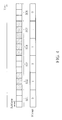
- Fig. 4 is a schematic diagram of a subframe allocation via a bitmap according to an example of the present invention.
- a size of a subframe group is 3 subframes, and at most 6 subframe groups SG1-SG6 (i.e., 18 subframes) may be indicated by the network to a MTC device.
- the network may determine to allocate the subframe groups SG2, SG4 and SG5 to the MTC device.
- the network determines a bitmap "010110" where the bits correspond to the subframe groups SG1-SG6, respectively, and transmits the bitmap to the MTC device.
- the MTC device maps the bitmap to the subframe groups SG1-SG6 in an order of increasing time, after receiving the bitmap transmitted by the network. Then, the MTC device may determine that the subframe groups SG2, SG4 and SG5 are available for receiving the PDSCH (or for transmitting the PUSCH) according to the bitmap.
- the process 50 includes the following steps:
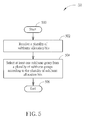
- Fig. 6 is a flowchart of a process 60 according to an example of the present invention.
- the process 60 may be utilized in the network (e.g., an eNB) shown in Fig. 1 , to indicate a subframe allocation to a MTC device.
- the process 60 may be compiled into the program code 214 and includes the following steps:
- the network selects a plurality of subframes from potential scheduled subframes, and determines a starting subframe of the plurality of subframes and a length of the plurality of subframes. Then, the network transmits an indication (e.g., subframe indication value (SIV)) corresponding to the starting subframe and the length to the MTC device, to indicate the plurality of subframes to the MTC device. That is, the starting subframe and the length are used for indicating (i.e., allocating) the plurality of subframes to the MTC device. Thus, the subframe(s) is allocated to the MTC device efficiently.
- an indication e.g., subframe indication value (SIV)
- the plurality of subframes in the process 60 may be consecutive subframes. That is, the length of the plurality of subframes is a number of the plurality of subframes indicated to the MTC device.
- the plurality of subframes may be non-consecutive subframes.
- a distance between each two neighboring subframes of the plurality of subframes may a fixed value (e.g., predetermined value), may be indicated by the indication, may be configured by a RRC signalling, or may be a function of the potential scheduled subframes. That is, the distance may be determined according any of the above methods, and is not limited herein. Further, the indication may further correspond to the distance.
- the indication may indicate the starting subframe, the length and the distance.
- the indication may be transmitted via in a DCI to the MTC device.
- the plurality of subframes may be allocated for a PDSCH or a PUSCH. That is, the MTC device may receive the PDSCH or transmit the PUSCH via the plurality of subframes indicated by the network.
- L Subframes ⁇ 1 and L Subframes ⁇ N Subframes - Subframe start should be satisfied.
- Fig. 7 is a schematic diagram of a subframe allocation via a starting subframe and a length of allocated subframes according to an example of the present invention.
- the network may determine to allocate subframes SF0-SF7 to the MTC device.
- the network determines an indication corresponding to the subframe SF0 and 8 which is the length of the allocated subframes, and transmits the indication to the MTC device.
- the MTC device determines that the subframes SF0-SF7 are available for receiving the PDSCH (or for transmitting the PUSCH) according to the indication, after receiving the indication.
- the process 80 includes the following steps :
- Fig. 9 is a flowchart of a process 90 according to an example of the present invention.
- the process 90 may be utilized in the network (e.g., an eNB) shown in Fig. 1 , to indicate a subframe allocation to a MTC device.
- the process 90 may be compiled into the program code 214 and includes the following steps:
- the network selects at least one subframe group from potential scheduled subframes, and determines at least one starting subframe (e.g., at least one index of the at least one starting subframe) of the at least one subframe group and at least one ending subframe (e.g., at least one index of the at least one ending subframe) of the at least one subframe group. Then, the network transmits a combinatorial index corresponding to the at least one starting subframe and the at least one ending subframe to the MTC device, to indicate the at least one subframe group to the MTC device. That is, the combinatorial index representing the at least one starting subframe and the at least one ending subframe is used for indicating (i.e., allocating) to the MTC device.
- the combinatorial index representing the at least one starting subframe and the at least one ending subframe is used for indicating (i.e., allocating) to the MTC device.
- a size of each of the at least one subframe group in the process 90 may be one. That is, each of the at least one subframe group may include only one subframe. In this situation, a starting subframe and an ending subframe of a subframe (i.e., subframe group with only one subframe) are the same, and the combinatorial index actually corresponds to only the starting subframe (or the ending subframe).
- each of the at least one subframe group may include consecutive subframes. That is, subframe(s) within a starting subframe and an ending subframe are all allocated to the MTC device.
- a number of the at least one subframe group in the process 90 may be a fixed value (e.g., predetermined value), or may be a function of the potential scheduled subframes. That is, the number of the at least one subframe group may be determined according any of the above methods, and is not limited herein.
- the combinatorial index may be transmitted via in a DCI to the MTC device.
- the at least one subframe group may be allocated for a PDSCH or a PUSCH. That is, the MTC device may receive the PDSCH or transmit the PUSCH via the at least one subframe group (i.e., subframes therein) indicated by the network.
- a combinatorial index c may consist of ⁇ log 2 ⁇ ⁇ N Subframe / S + 1 ⁇ 2 ⁇ X ⁇ bits, where S is a size of a subframe group, X is the number of selected subframe groups which may be a predetermined value or a function of N Subframe , the total number of potential scheduled subframes.
- the combinatorial index c corresponds to a starting index x 0 and an ending index x 1 - 1 of a subframe set 1, a starting index x 2 and an ending index x 3 - 1 of a subframe set 1, and so on.
- the number of repetition of data transmissions may be implicitly determined in the abovementioned subframe allocations.
- the number of scheduled subframes may represent the number of repetition of the data transmissions.
- the number of repetition of the data transmissions is known beforehand (e. g. , during the MTC configuration or related procedure(s)). In this situation, a MTC device may be indicated only the location information of the scheduled subframe with full scheduling flexibility by a combinatorial index d.
- the combinatorial index d may consist of ⁇ log 2 ⁇ ⁇ N Subframe / S + 1 ⁇ R / S ⁇ , where R is the number of repetition of the data transmissions, S is the subframe group size which can be 1, and N Subframe is the total number of potential scheduled subframes.
- , M R/S, and s i is the selected subframe group in the increasing time order.
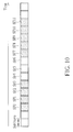
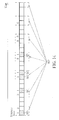
- Fig. 10 is a schematic diagram of a subframe allocation via starting subframes and ending subframes of allocated subframes according to an example of the present invention.
- subframes SF0-SF11 are available for resource allocation, and the network may determine to allocate the subframes SF0-SF3 (i.e., the first subframe group) and the subframes SF7-SF11 (i.e., the second subframe group) to the MTC device.
- the network determines starting subframes as the subframes SF0 and SF7, and determines ending subframes as the subframes SF3 and SF11.
- the network determines a combinatorial index according to the starting subframes and the ending subframes, and transmits the combinatorial index to the MTC device. Then, the MTC device determines that the subframes SF0-SF3 and SF7-SF11 are available for receiving the PDSCH (or for transmitting the PUSCH) according to the combinatorial index, after receiving the combinatorial index.
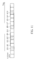
- Fig. 11 is a schematic diagram of a subframe allocation via starting subframes of allocated subframes according to an example of the present invention.
- subframes SF0-SF10 are available for resource allocation, and the network may determine to allocate the subframes SF0, SF3, SF6 and SF10 to the MTC device.
- the network determines starting subframes (i.e., ending subframes) as the subframes SF0, SF3, SF6 and SF10.
- the network determines a combinatorial index according to the starting subframes, and transmits the combinatorial index to the MTC device.
- the MTC device determines that the subframes SF0, SF3, SF6 and SF10 are available for receiving the PDSCH (or for transmitting the PUSCH) according to the combinatorial index, after receiving the combinatorial index.
- the process 120 includes the following steps:
- Fig. 13 is a flowchart of a process 130 according to an example of the present invention.
- the process 130 may be utilized in the network (e.g., an eNB) shown in Fig. 1 , to indicate a subframe allocation to a MTC device.
- the process 130 may be compiled into the program code 214 and includes the following steps:
- the network selects a subframe subset from a plurality of subframe subsets, determines a shift for the subframe subset, and determines a bitmap indicating a plurality of subframes in the subframe subset according to the shift. Then, the network transmits a plurality of bits indicating the subframe subset, the shift and the bitmap to the MTC device, to indicate the plurality of subframes to the MTC device. That is, the bitmap and the shift are used for indicating the plurality of subframes in the subframe set, after the subframe set is selected. The plurality of bits are used for representing the subframe subset, the bitmap and the shift, which may correspond to three subsets of the bits, respectively. Thus, the subframe(s) is allocated to the MTC device efficiently.
- a subframe subset (e.g., subframe group subset) s , where 0 ⁇ s ⁇ S, consists of every S th subframe subsets starting from the subframe set s.
- the network may transmit a subframe allocation information consisting of 3 fields to a MTC device, to indicate a plurality of subframes to the MTC device.
- the first field with ⁇ log 2 ( S ) ⁇ bits may be used to indicate a selected subframe subset among the S subframe subsets.
- the second field with one bit may be used to indicate a shift of subframe allocation within the selected subframe subset. For example, a bit "1" indicates the shift is triggered, and the shift is not triggered otherwise.
- the third field includes a bitmap, where each bit of the bitmap addresses a corresponding subframe in the selected subframe subset in such a way that a MSB to a LSB of the bitmap are mapped to the subframes in the increasing time order.
- a subframe in the selected subframe set is allocated to the MTC device if the corresponding bit in the bitmap is "1", and a subframe is not allocated to the MTC device otherwise.
- the addressable subframe numbers of the selected subframe subset start from an offset, ⁇ shift ( s ) to the smallest subframe number within the selected subframe subset, which is mapped to the MSB of the bitmap.
- Fig. 14 is a schematic diagram of a subframe allocation via a subframe subset, a shift and a bitmap according to an example of the present invention.
- the network selects a subframe subset SS0 from a plurality of subframe subsets.
- the network also determines that a shift is not triggered. That is, a bitmap is used from the left side of the subframe subset SSO. Accordingly, the network determines the bitmap as "10011101000", to indicating subframes SF0-SF4 in the subframe subset SS0 to a MTC device.
- the network transmits bits "0010011101000” to a MTC device, to indicate the subframes SF0-SF4 to the MTC device, wherein the first bit “0” denotes the subframe subset SS0, the second bit “0” denotes that the shift is not used, and the rest bits denote the subframe allocation in the subframe subset SS0.
- the MTC device After receiving the bits "0010011101000", the MTC device first selects the subframe subset SS0 from the subframe subsets. Then, the MTC device maps the bitmap to the subframe subset SS0 from the left side of the subframe subset SS0, and determines that the subframes SF0-SF4 are allocated.
- the process 150 includes the following steps:
- Examples of the hardware may include analog circuit(s), digital circuit (s) and/or mixed circuit(s).
- the hardware may include ASIC(s), field programmable gate array(s) (FPGA(s)), programmable logic device(s), coupled hardware components or combination thereof.
- the hardware may include general-purpose processor(s), microprocessor(s), controller(s), digital signal processor(s) (DSP(s)) or combination thereof.
- Examples of the software may include set(s) of codes, set(s) of instructions and/or set(s) of functions retained (e.g., stored) in a storage unit, e.g., a computer-readable medium.
- the computer-readable medium may include SIM, ROM, flash memory, RAM, CD-ROM/DVD-ROM/BD-ROM, magnetic tape, hard disk, optical data storage device, non-volatile storage unit, or combination thereof.
- the computer-readable medium (e.g., storage unit) may be coupled to at least one processor internally (e.g., integrated) or externally (e.g., separated).
- the at least one processor which may include one or more modules may (e.g., be configured to) execute the software in the computer-readable medium.
- the set(s) of codes, the set(s) of instructions and/or the set(s) of functions may cause the at least one processor, the module(s), the hardware and/or the electronic system to perform the related steps.
- Examples of the electronic system may include a system on chip (SoC), system in package (SiP), a computer on module (CoM), a computer program product, an apparatus, a mobile phone, a laptop, a tablet computer, an electronic book or a portable computer system, and the communication device 20.
- SoC system on chip
- SiP system in package
- CoM computer on module
- a computer program product an apparatus, a mobile phone, a laptop, a tablet computer, an electronic book or a portable computer system, and the communication device 20.
- the present invention provides a communication device (e.g., an eNB) for indicating a subframe allocation to a MTC device.
- a communication device e.g., an eNB
- flexibility of cross-subframe scheduling and repetition of transmission are achieved, while signalling overhead needed for a control channel is reduced.
Landscapes
- Engineering & Computer Science (AREA)
- Signal Processing (AREA)
- Computer Networks & Wireless Communication (AREA)
- Mobile Radio Communication Systems (AREA)
- Transceivers (AREA)
Priority Applications (1)
| Application Number | Priority Date | Filing Date | Title |
|---|---|---|---|
| EP17150478.0A EP3171654A1 (fr) | 2014-06-12 | 2015-06-12 | Dispositif de gestion d'attribution de sous-trame avec répétition pour amélioration de couverture de mtc |
Applications Claiming Priority (1)
| Application Number | Priority Date | Filing Date | Title |
|---|---|---|---|
| US201462011051P | 2014-06-12 | 2014-06-12 |
Related Child Applications (1)
| Application Number | Title | Priority Date | Filing Date |
|---|---|---|---|
| EP17150478.0A Division EP3171654A1 (fr) | 2014-06-12 | 2015-06-12 | Dispositif de gestion d'attribution de sous-trame avec répétition pour amélioration de couverture de mtc |
Publications (2)
| Publication Number | Publication Date |
|---|---|
| EP2955968A2 true EP2955968A2 (fr) | 2015-12-16 |
| EP2955968A3 EP2955968A3 (fr) | 2016-03-02 |
Family
ID=53496404
Family Applications (2)
| Application Number | Title | Priority Date | Filing Date |
|---|---|---|---|
| EP15171778.2A Withdrawn EP2955968A3 (fr) | 2014-06-12 | 2015-06-12 | Dispositif de gestion d'attribution de sous-trame à un dispositif mtc |
| EP17150478.0A Withdrawn EP3171654A1 (fr) | 2014-06-12 | 2015-06-12 | Dispositif de gestion d'attribution de sous-trame avec répétition pour amélioration de couverture de mtc |
Family Applications After (1)
| Application Number | Title | Priority Date | Filing Date |
|---|---|---|---|
| EP17150478.0A Withdrawn EP3171654A1 (fr) | 2014-06-12 | 2015-06-12 | Dispositif de gestion d'attribution de sous-trame avec répétition pour amélioration de couverture de mtc |
Country Status (2)
| Country | Link |
|---|---|
| US (1) | US20150365921A1 (fr) |
| EP (2) | EP2955968A3 (fr) |
Families Citing this family (23)
| Publication number | Priority date | Publication date | Assignee | Title |
|---|---|---|---|---|
| US9603163B2 (en) * | 2012-11-01 | 2017-03-21 | Lg Electronics Inc. | Method and apparatus for supporting scheduling groups of devices characteristics in a wireless communication system |
| CN107079446B (zh) * | 2014-09-26 | 2021-08-17 | Lg 电子株式会社 | 在无线通信系统中通过终端发送和接收信号的方法和设备 |
| US20210195586A1 (en) * | 2016-03-15 | 2021-06-24 | Lg Electronics Inc. | Method by which base station and terminal transmit/receive signal in wireless communication system, and device for supporting same |
| US11337265B2 (en) | 2017-08-10 | 2022-05-17 | Comcast Cable Communications, Llc | Beam failure recovery request transmission |
| US10887939B2 (en) | 2017-08-10 | 2021-01-05 | Comcast Cable Communications, Llc | Transmission power control for beam failure recovery requests |
| US11950287B2 (en) | 2017-08-10 | 2024-04-02 | Comcast Cable Communications, Llc | Resource configuration of beam failure recovery request transmission |
| US10855359B2 (en) | 2017-08-10 | 2020-12-01 | Comcast Cable Communications, Llc | Priority of beam failure recovery request and uplink channels |
| US11277301B2 (en) | 2017-09-07 | 2022-03-15 | Comcast Cable Communications, Llc | Unified downlink control information for beam management |
| TWI705675B (zh) * | 2017-09-08 | 2020-09-21 | 華碩電腦股份有限公司 | 無線通訊系統中在非授權頻譜中考慮波束成形傳輸的通道使用的方法和設備 |
| US11611468B2 (en) * | 2017-09-28 | 2023-03-21 | Comcast Cable Communications, Llc | Beam management with DRX configuration |
| US10660063B2 (en) | 2017-11-16 | 2020-05-19 | Comcast Cable Communications, Llc | Beam paging assistance |
| US10863570B2 (en) | 2018-01-09 | 2020-12-08 | Comcast Cable Communications, Llc | Beam selection in beam failure recovery request retransmission |
| EP3525516B1 (fr) | 2018-02-09 | 2022-08-31 | Comcast Cable Communications, LLC | Procédure de récupération d'échec de faisceau dans une agrégation de porteuses |
| CA3034014A1 (fr) | 2018-02-15 | 2019-08-15 | Comcast Cable Communications, Llc | Signalement de defaut de faisceau |
| EP4239905A3 (fr) | 2018-03-30 | 2023-10-18 | Comcast Cable Communications LLC | Configuration pour reprise après défaillance de faisceau |
| US11039350B2 (en) | 2018-04-02 | 2021-06-15 | Comcast Cable Communications, Llc | Beam failure recovery |
| EP3930237A1 (fr) | 2018-05-10 | 2021-12-29 | Comcast Cable Communications, LLC | Priorisation dans des procédures de reprise après défaillance de faisceau |
| EP3609285B1 (fr) | 2018-08-09 | 2021-10-06 | Comcast Cable Communications, LLC | Gestion de ressources pour des procédures de reprise après défaillance de faisceau |
| CA3056500A1 (fr) | 2018-09-24 | 2020-03-24 | Comcast Cable Communications, Llc | Procedures de reprise apres une defaillance de faisceau |
| EP3629492B1 (fr) | 2018-09-25 | 2026-01-07 | Ofinno, LLC | Configuration de faisceau pour des cellules secondaires |
| US11419123B2 (en) * | 2019-05-03 | 2022-08-16 | Qualcomm Incorporated | Uplink transmission cancellation |
| EP3799518A1 (fr) * | 2019-09-27 | 2021-03-31 | Apple Inc. | Transmission d'une requête de récupération d'une liaison de cellules secondaires |
| CN119893602A (zh) * | 2019-09-27 | 2025-04-25 | 苹果公司 | 辅助小区链路恢复请求传输 |
Family Cites Families (4)
| Publication number | Priority date | Publication date | Assignee | Title |
|---|---|---|---|---|
| KR20120039847A (ko) * | 2010-10-18 | 2012-04-26 | 삼성전자주식회사 | 통신 시스템에서 동적으로 자원을 할당하기 위한 장치 및 방법 |
| US8848591B2 (en) * | 2012-02-27 | 2014-09-30 | Futurewei Technologies, Inc. | System and method for message acknowledgment feedback for device-to-device communication overlaid on a cellular network |
| CN103796327A (zh) * | 2012-10-29 | 2014-05-14 | 中兴通讯股份有限公司 | 一种子帧调度方法、系统及网络设备、终端 |
| EP2936910B1 (fr) * | 2012-12-21 | 2016-10-05 | Telefonaktiebolaget LM Ericsson (publ) | Secteurs de trame non consécutifs dans des messages d'ordonnancement multi-tti |
-
2015
- 2015-06-11 US US14/737,482 patent/US20150365921A1/en not_active Abandoned
- 2015-06-12 EP EP15171778.2A patent/EP2955968A3/fr not_active Withdrawn
- 2015-06-12 EP EP17150478.0A patent/EP3171654A1/fr not_active Withdrawn
Non-Patent Citations (1)
| Title |
|---|
| NTT DOCOMO: "Views on PDSCH Coverage Enhancement", vol. RAN WG1, no. San Francisco, USA; 20131111 - 20131115, 13 November 2013 (2013-11-13), XP050735184, Retrieved from the Internet <URL:http://www.3gpp.org/ftp/Meetings_3GPP_SYNC/RAN/RAN1/Docs/> [retrieved on 20131113] * |
Also Published As
| Publication number | Publication date |
|---|---|
| US20150365921A1 (en) | 2015-12-17 |
| EP2955968A3 (fr) | 2016-03-02 |
| EP3171654A1 (fr) | 2017-05-24 |
Similar Documents
| Publication | Publication Date | Title |
|---|---|---|
| EP3171654A1 (fr) | Dispositif de gestion d'attribution de sous-trame avec répétition pour amélioration de couverture de mtc | |
| EP3939368B1 (fr) | Procédé et appareil de multiplexage d'uci | |
| JP6082121B2 (ja) | 情報送信方法、ユーザ装置及び基地局 | |
| EP2779514B1 (fr) | Transmission de signaux de référence de sondage configurés de manière adaptative pour systèmes de communication TDD | |
| EP3308593B1 (fr) | Procédé et appareil de réduction de latence de transmissions de liaison montante lte | |
| US10349391B2 (en) | Physical downlink data channel transmission method, base station, and user equipment | |
| EP3379883B1 (fr) | Procédé et station mobile permettant la transmission d'un service | |
| US20170311196A1 (en) | Method of Handling Channel Status Information and Related Communication Device | |
| CN107431605A (zh) | 在无线通信网络中传递控制数据 | |
| EP2922366A2 (fr) | Procédé de gestion de fonctionnement de dispositif à dispositif | |
| EP3349502A1 (fr) | Dispositif et procédé de traitement de rapports d'information d'état de canal pour intervalles de temps de transmission | |
| EP2953288B1 (fr) | Procédé de gestion d'état de marche-arrêt d'une cellule | |
| US11284390B2 (en) | Data communication method, terminal device, and network device | |
| EP2696529A2 (fr) | Procédé de traitement d'opération de communication dans un système TDD et appareil associé | |
| EP2983321A2 (fr) | Dispositif et procédé de gestion de communication de dispositif à cellulaire | |
| EP3190740A2 (fr) | Dispositif et procédé de gestion de transmission/réception pour cellule de desserte | |
| EP2870811B1 (fr) | Procédé et noeud de réseau permettant d'allouer des ressources d'une sous-trame de liaison montante | |
| US9929799B2 (en) | Network and user equipment of HD-FDD communication system for handling HARQ | |
| US9191938B2 (en) | Method of handling control channel and related communication device | |
| EP4131821A1 (fr) | Dispositif et procédé de gestion de transmission de demande de répétition automatique hybride | |
| US11647507B2 (en) | Device and method for handling physical uplink control channel collision | |
| US20160227568A1 (en) | Method of Handling Carrier Grouping and Related Communication Device |
Legal Events
| Date | Code | Title | Description |
|---|---|---|---|
| PUAI | Public reference made under article 153(3) epc to a published international application that has entered the european phase |
Free format text: ORIGINAL CODE: 0009012 |
|
| 17P | Request for examination filed |
Effective date: 20150612 |
|
| AK | Designated contracting states |
Kind code of ref document: A2 Designated state(s): AL AT BE BG CH CY CZ DE DK EE ES FI FR GB GR HR HU IE IS IT LI LT LU LV MC MK MT NL NO PL PT RO RS SE SI SK SM TR |
|
| AX | Request for extension of the european patent |
Extension state: BA ME |
|
| PUAL | Search report despatched |
Free format text: ORIGINAL CODE: 0009013 |
|
| AK | Designated contracting states |
Kind code of ref document: A3 Designated state(s): AL AT BE BG CH CY CZ DE DK EE ES FI FR GB GR HR HU IE IS IT LI LT LU LV MC MK MT NL NO PL PT RO RS SE SI SK SM TR |
|
| AX | Request for extension of the european patent |
Extension state: BA ME |
|
| RIC1 | Information provided on ipc code assigned before grant |
Ipc: H04W 72/04 20090101AFI20160128BHEP Ipc: H04L 5/00 20060101ALN20160128BHEP |
|
| 17Q | First examination report despatched |
Effective date: 20160222 |
|
| RBV | Designated contracting states (corrected) |
Designated state(s): AL AT BE BG CH CY CZ DE DK EE ES FI FR GB GR HR HU IE IS IT LI LT LU LV MC MK MT NL NO PL PT RO RS SE SI SK SM TR |
|
| STAA | Information on the status of an ep patent application or granted ep patent |
Free format text: STATUS: THE APPLICATION IS DEEMED TO BE WITHDRAWN |
|
| 18D | Application deemed to be withdrawn |
Effective date: 20190103 |