EP2955992B1 - Lame de tondeuse remplaçable et ensemble - Google Patents
Lame de tondeuse remplaçable et ensemble Download PDFInfo
- Publication number
- EP2955992B1 EP2955992B1 EP14711029.0A EP14711029A EP2955992B1 EP 2955992 B1 EP2955992 B1 EP 2955992B1 EP 14711029 A EP14711029 A EP 14711029A EP 2955992 B1 EP2955992 B1 EP 2955992B1
- Authority
- EP
- European Patent Office
- Prior art keywords
- mounting member
- blade
- attachment mechanism
- central portion
- replacement
- Prior art date
- Legal status (The legal status is an assumption and is not a legal conclusion. Google has not performed a legal analysis and makes no representation as to the accuracy of the status listed.)
- Active
Links
Images



Classifications
-
- A—HUMAN NECESSITIES
- A01—AGRICULTURE; FORESTRY; ANIMAL HUSBANDRY; HUNTING; TRAPPING; FISHING
- A01D—HARVESTING; MOWING
- A01D34/00—Mowers; Mowing apparatus of harvesters
- A01D34/01—Mowers; Mowing apparatus of harvesters characterised by features relating to the type of cutting apparatus
- A01D34/412—Mowers; Mowing apparatus of harvesters characterised by features relating to the type of cutting apparatus having rotating cutters
- A01D34/63—Mowers; Mowing apparatus of harvesters characterised by features relating to the type of cutting apparatus having rotating cutters having cutters rotating about a vertical axis
- A01D34/73—Cutting apparatus
- A01D34/733—Cutting-blade mounting means
Definitions
- the present invention relates to lawn and garden equipment, and more particularly, to a replaceable blade assembly for a mower.
- Lawn mowers such as walk-behind mowers, riding mowers, garden tractors, and the like include a cutting deck that includes at least one cutting blade configured to cut grass and other vegetation.
- the cutting blade often contacts rocks, tree branches, or other debris which causes the blade to dull or otherwise become ineffective.
- Typical changeable blades for rotary mowers include one-piece blades that are attached and retained using hardware which requires tools to remove and replace the blade, pivot-blades attached onto one-piece mounting plates which also require tools to remove and replace the blade, and one-piece blades that are attached and retained but do not require tools for removal and replacement. Replacement of the one-piece blades involves replacing the entire blade even though one of the sharpened edges may not need replacement.
- the one-piece blades are also typically designed for finish-cut operations, and where durability and impact strength are major concerns, damage to spindles, motors and engine crankshafts with one piece blades might not be avoidable.
- Pivot-blades are often used in rough-cut operations and typically do not produce high cutting quality. Examples of replaceable blades are provided in patent documents NL8403911A , US3958402A and US4712364A .
- the cutting blades need to be stable and solidly retained to provide the highest quality of cut and safe operation.
- Object of the present invention is to provide a replaceable blade for attachment to a mounting member of a lawn mower, which overcomes the above mentioned drawbacks; this object is achieved by the replaceable blade of the appended claims.
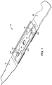
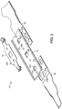
- the blade assembly 10 includes a mounting member 12, a pair of opposing replaceable blades 16, and a plurality of attachment mechanisms for releasably attaching each of the replaceable blades 16 to the mounting member 12.
- the attachment mechanisms are configured to allow each blade 16 to be attachable to any end of the mounting member 12 while also preventing the blade 16 from being attached to the mounting member 12 in an upside-down manner. Improper attachment of the blade(s) 16 to the mounting member 12 causes a rotational imbalance of the blade assembly 10 which, in turn, causes immediate wear-and-tear on the engine and rotational components thereof due to the shaking and vibrations caused by the rotational imbalance of the blade assembly 10.
- the mounting member 12 is operatively positioned within a cutting deck of any type of lawn mower, including a walk-behind style lawn mower, a garden tractor, a riding lawn mower, or the like.
- the blade assembly 10 is connected to a motor or engine crankshaft (not shown) that extends downwardly through the cutting deck.
- the blade assembly 10 is connected to a rotatable spindle (not shown) located within a cutting deck.
- the blade assembly 10 is removably connected within the deck and is rotatable about a substantially vertical rotational axis defined by the motor or engine crankshaft or the spindle to which it is attached.
- the mounting member 12 is an elongated structural member that provides a base for receiving at least one removably attachable replacement blade 16.
- the mounting member 12 includes a first end 18, a second end 20 opposite the first end 18, an upper surface 22, an opposing lower surface 24, a first side edge 26 extending between the opposing ends 18, 20, and an opposing second side edge 28.
- the upper and lower surfaces 22, 24 form a substantially planar central portion of the mounting member 12.
- the opposing side edges 26, 28 extend from the central portion in a curved manner. In an embodiment, the side edges 26, 28 are curved upwardly relative to the upper surface 22 of the mounting member 12.
- the side edges 26, 28 are curved in a corresponding direction such that the mounting member 12 has a C-shaped or channel-shaped cross-section.
- the C-shaped cross-sectional shape increases the beam strength of the mounting member 12.
- the mounting member 12 may also have any other similar cross-sectional shape that increases the beam strength.
- the curved side edges 26, 28 provide additional structural stiffness or rigidity to the mounting member 12 to resist longitudinal bending and torsional rotation while minimizing losses in efficiency due to contact with the cut grasses.
- the side edges 26, 28 are curved relative to the upper surface 22 at an angle of between about 30° to 90°.
- the opposing side edges 26, 28 of the mounting member 12 are curved downwardly toward the lower surface 24 of the mounting member 12.
- the central portion of the mounting member 12 is substantially planar between the opposing side edges 26, 28 such that the opposing side edges 26, 28 are not curved and remain substantially coplanar with the upper and lower surfaces 22, 24.
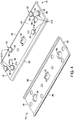
- the mounting member 12 includes a central bore 30 formed through the thickness thereof, as shown in FIGS. 1-4 .
- the central bore 30 is sized and shaped to receive a rotatable driving member such as a motor or engine crankshaft, a spindle, an adaptor, or any other rotatable member configured to be positioned within the central bore to cause the blade assembly 10 to selectively rotate about an axis substantially perpendicular to the upper surface 22.
- the central bore 30 has a generally elongated X-shape, as shown in FIG. 4 .
- the central bore 30 has a six-point star shape, as shown in FIG. 7 . It should be understood by one of ordinary skill in the art that the central bore 30 can be formed of any shape sufficient to receive a rotatable member that causes the blade assembly 10 to rotate thereabout.
- the mounting member 12 includes a first attachment mechanism 210 formed of a plurality of caps 32 extending from the mounting member 12 for providing a releasable attachment between the replacement blades 16 and the mounting member 12.
- the first attachment mechanism 210 is positioned adjacent to both the first end 18 and the opposing second end 20 thereof.
- the first attachment mechanism 210 provides a male portion of a male-female connection.
- the first attachment mechanism 210 operatively connected to the mounting member 12 may include the female portion of a male-female connection.
- Each first attachment mechanism 210 on the mounting member 12 is configured to cooperate with a corresponding attachment mechanism operatively connected to each blade 16. It should be understood by one of ordinary skill in the art that the first attachment mechanism 210 can be formed of any mechanical connection that allows for a tool-less quick-release and quick-attachment of a blade 16 to a distal end 18, 20 of the mounting member 12.
- the first attachment mechanism 210 is located adjacent to both the first end 18 and the second end 20 of the mounting member 12, wherein each first attachment mechanism 210 includes at least one cap 32 that extends perpendicularly away from the lower surface 24 of the mounting member 12.
- the illustrated exemplary embodiment of the first attachment mechanism 210 includes three caps 32 extending from the lower surface 24 of the mounting member 12, as shown in FIG. 4 . It should be understood by one of ordinary skill in the art that although the illustrated embodiment includes three (3) caps 32, the first attachment mechanism 210 can include any number of caps extending from the lower surface 24 of the mounting member 12.
- each cap 32 protrude from the mounting member 12, and each cap 32 includes a base 34 that extends substantially linearly away from the lower surface 24 and a flange 36 that extends substantially perpendicular and radially from the base 34.
- the flange 36 is spaced apart relative to the lower surface 24, thereby providing a shoulder bolt having a gap between the base 34 and the outer radial edge of the flange 36 to create a shoulder between the flange 36 and the lower surface 24 of the mounting member 12.
- the base 34 is a cylindrical member having a circular cross-sectional shape extending from the lower surface 24 of the mounting member 12.
- the cross-sectional shape of the base 34 can be oval, triangular, square, or the base 34 may include a plurality of vertically-oriented splines, a keying protrusion, half of a yin/yang, or any symmetrical or non-symmetrical shape.
- the flange 36 is a round, substantially flat plate mounted atop the end of the base 34.
- the planar shape of the flange 36 can also be square, tear-dropped, half of a yin/yang, M-shaped, oval, square, triangular, or any symmetrical or non-symmetrical shape.
- the base 34 and flange 36 can be any shape sufficient to allow the blades 16 to be releasably attachable to the mounting member 12 by way of the caps 32.
- the caps 32 can be formed of separate parts such as the bases 34 and flanges 36 formed separately and then fixedly attached to each other or they could be integrally formed together in which the bases 34 and the flanges 36 are formed as a single member.
- each cap 32 has the same size and shape.
- at least one cap 32 is sized differently than the other caps 32.
- one cap 32 may include a larger base 34, a larger flange 36, or a combination of both relative to the other caps 32.
- one cap 32 may have a square base 34, a square flange 36, or a combination of both while all other caps 32 have a circular base and circular flange 36.
- one cap 32 may have a circular base 34 and a square flange 36 while all other caps 32 have a circular base and circular flange 36.
- all of the caps 32 of the first attachment mechanism 210 positioned adjacent to each opposing distal end 18, 20 extend from the lower surface 24 of the mounting member 12.
- all of the caps 32 for the first attachment mechanism 210 for connecting the blades 16 to a respective end of the mounting member 12 extend from a surface of the blade 16 and the caps 32 are received by the mounting member 12.
- at least one of the caps 32 from a first attachment mechanism 210 extends from the lower surface 24 of the mounting member 12 and at least another cap 32 extends from the corresponding blade 16, wherein each of the caps 32 is configured to assist in attaching the blade 16 to the mounting member 12.
- caps 32 of the first attachment mechanism 210 The function of the caps 32 of the first attachment mechanism 210 is to allow the replacement blades 16 to be selectively and releasably connectable to the mounting member 12, as will be explained below.
- the caps 32 of each of the first attachment mechanism 210 positioned adjacent to the first and second ends 18, 20 of the mounting member form two opposing patterns of caps 32, wherein each pattern includes three (3) caps 32.
- Each first attachment mechanism 210 should include at least one cap 32, wherein the cap(s) form a pattern.
- the first attachment mechanism 210 may include any number of caps 32 for operatively connecting a replacement blade 16 to the mounting member 12, but a pattern having at least three caps 32 is preferable to more evenly distribute the stresses transferred to the mounting member 12 by the replacement blades 16 while utilizing the fewest number of caps 32.
- each first attachment mechanism 210 includes a pattern of three caps 32, and the pattern of caps 32 is arranged such that the linear alignment between any two of the caps 32 is not parallel to the longitudinal or transverse axes of the replacement blade 16 or the mounting member 12 to which they are attached.
- At least two of the caps 32 of a first attachment mechanism 210 are aligned such that the linear alignment of the caps 32 is parallel or perpendicular to the longitudinal axis of the mounting member 12.
- the pattern of the caps 32 of each first attachment mechanism 210 is identical such that a replacement blade 16 having a pattern of connecting mechanism that cooperates with the caps 32 can be attached to either end of the mounting member 12.
- the pattern of the caps 32 of the opposing first attachment mechanisms 210 is different such that the replacement blades 16 are configured to be attachable to only one of the ends of the mounting member 12 without being attachable to any other end of the mounting member.
- the pattern of caps 32 forming the first attachment mechanism 210 is asymmetrical about the longitudinal axis of the blade 16, as shown in FIG. 4 . In another embodiment, the pattern of caps 32 forming the first attachment mechanism 210 is symmetrical about the longitudinal axis of the blade 16.
- the caps 32 can also be arranged in a pattern that ensures proper replacement blade orientation and alignment when installed, wherein the pattern allows the blade 16 to be attached such that the tip portion of the blade 16 is properly oriented during rotation.
- the caps 32 are welded to the mounting member 12 or blade 16.
- the caps 32 are riveted to the mounting member 12 or blade. It should be understood by one of ordinary skill in the art that the caps 32 can be attached to the mounting member 12 or the blade 16 in any manner so as to provide a fixed rigid connection therebetween.
- first attachment mechanism 210 is described above as including a plurality of caps 32 for providing a male-female connection, it should be understood by one of ordinary skill in the art that the first attachment mechanism 210 can include any form of male or female connector that is receivable by a corresponding female or male connector of an attachment mechanism for connecting a blade 16 to the mounting member 12.
- a second attachment mechanism 212 for releasably connecting the blades 16 to the mounting member 12 is formed as an indexing member 14, as shown in FIGS. 1 , 3 , and 5 .
- the indexing member 14 of the second attachment mechanism 212 cooperates with a corresponding attachment mechanism included on both the mounting member 12 and each blade 16 for receiving the indexing member 14, as will be explained below.
- the attachment mechanism on the mounting member 12 configured to receive the indexing member 14 is a third attachment mechanism 214 positioned adjacent to both the first and second distal ends 18, 20 thereof.
- Each third attachment mechanism 214 included on the mounting member 12 is formed of an indexing aperture 38 formed through the thickness of the mounting member 12, as shown in FIG.
- each blade 16 is configured to receive the indexing member 14 when the respective blade 16 is properly aligned and attached to the mounting member 12.
- the indexing apertures 38 have a substantially circular shape, but it should be understood by one of ordinary skill in the art that the indexing apertures 38 can be formed as any shape that corresponds to the pins 44 of the indexing member 14.
- the second attachment mechanism 212 is formed as an indexing member 14.
- Cooperating and corresponding indexing apertures 38, 60 are formed into the mounting member 12 and replacement blades 16 for receiving the indexing member 14 when each blade 16 is positively positioned with respect to the mounting member 12.
- the indexing member 14 is fixedly attached to the mounting member 12.
- the indexing member 14 is positioned adjacent to the upper surface 22 of the mounting member 12 and is secured in a sandwiching manner between the mounting member 12 and the motor or engine crankshaft, the spindle, or an adaptor attached to the crankshaft or spindle.
- the indexing member 14 is an elongated member having a rectangular base 40, a pair of arms 42 extending from opposing ends of the base 40, and a pin 44 or tab extending from the end of each arm 42 opposite the base 40. It should be understood by one of ordinary skill in the art that the indexing member 14 may be formed of any shape.
- the pins 44 are biased toward engagement with both the mounting member 12 and the blades 16 due to the cantilever configuration of the pins 44 being positioned at the distal end of the arms 42 with the base 40 being substantially stationary or otherwise operatively secured to the mounting member 12.
- Each pin 44 is movable or actuatable for selectively releasing or engaging a replacement blade 16 and the mounting member 12, as will be explained below.
- the arms 42 are aligned with the base 40, and each arm 42 has a width that is smaller than the width of the base 40.
- the arms 42 are illustrated as having a smaller width than the base 40 in the exemplary embodiment, it should be understood by one of ordinary skill in the art that the base 40 can also include the arms 42 such that the pins 44 extend from the base 40 which has a substantially consistent width along the length thereof.
- the arms 42 and the elongated base 40 are configured to act as cantilever springs when the indexing member 14 is secured about the central aperture 46.
- the pins 44 extend away from the plane of the base 40 and arms 42, wherein the pins 44 are configured to extend through the indexing aperture 38 ( FIG. 4 ) of the mounting member 12.
- Each pin 44 is configured to be selectively engaged with a replacement blade 16.
- FIG. 6 illustrates an exemplary embodiment of a replaceable replacement blade 16 that is configured to be selectively attachable to either the first end 18 or the second end 20 of the mounting member 12.
- the replacement blade 16 includes a central portion 48 and a tip portion 50 integrally formed with and extending from the central portion 48.
- the central portion 48 is configured to be operatively connected to the mounting member 12 while the tip portion 50 extends beyond the corresponding distal end 18, 20 of the mounting member 12 for cutting grass and vegetation.
- the central portion 48 includes an upper surface 52, a lower surface 54, opposing side edges 56, and at least one attachment mechanism.
- the central portion 48 of the blade includes a fourth attachment mechanism 216 and a fifth attachment mechanism 218.
- the upper and lower surfaces 52, 54 form a substantially flat body, and the opposing sides edges 56 extend from the body in a curved or formed angular sections.
- the side edges 56 of the replacement blade 16 have a similar curvature as the first and second side edges 26, 28 of the mounting member 12 such that when the replacement blade 16 is attached to the mounting member 12, the curved edges of both the mounting member 12 and the blade 16 form a nesting arrangement.
- the matching channel shapes of the central portion 48 of the replacement blade 16 and the mounting member 12 reduce the shear loading of the caps 32 during conditions such as blade impact, whereby a majority of impact energy between the replacement blade 16 and the object being impacted is diverted from shear to tension.
- the central portion 48 includes a first end 58 extending between the opposing side edges 56.
- first and second side edges 56, 58 are substantially aligned with the upper and lower surfaces 54, 56 in a co-planar manner, thereby forming a flat central portion 48.
- first end 58 includes a notch 69 formed therein, wherein the notch 69 is configured to provide clearance between the central portion 48 of the replacement blade 16 and an adapter (not shown) which is used to attach the replacement blade 16 to an engine crankshaft.
- an exemplary embodiment of the central portion 48 of the replacement blade 16 includes the fourth attachment mechanism 216 which is an indexing aperture 60 formed into the replacement blade 16 for receiving the indexing member 14.
- the indexing aperture 60 of the replacement blade 16 is configured to be alignable with the indexing aperture 38 of the mounting member 12 when the replacement blade 16 is properly seated against and attached to the mounting member 12.
- the indexing aperture 60 can be formed as any shape, but the shape of the indexing aperture 60 should be shaped to correspond to the shape of the indexing aperture 38 of the mounting member 12 and the shape of the pin 44 of the indexing member 14.
- the indexing aperture 60 forming the fourth attachment mechanism 216 in the illustrated exemplary embodiment, is surrounded by the fifth attachment mechanism 218 which is formed as a plurality of locking apertures 62, wherein each of the locking apertures 62 is configured to receive a corresponding cap 32 extending from the mounting member 12 for selectively attaching the blade 16 to the mounting member 12.
- the locking apertures 62 are formed as keyhole apertures which include a receiving portion 64 and a channel portion 66.
- the receiving portion 64 is a rounded hole formed through the thickness of the central portion 48 of the replacement blade 16.
- the receiving portion 64 is sized to allow the flange 36 of the cap 32 to pass through.
- the channel portion 66 is an elongated channel extending from the receiving portion 64.
- the channel portion 66 is sized to be substantially the same (or slightly larger) than the outer diameter of the base 34 of the cap 32 such that the base 34 is capable of sliding along the channel portion 66.
- the end of the channel portion 66 opposite the receiving portion 64 is configured to be a stop to prevent the replacement blade 16 from sliding past the end of the mounting member 12. It should be understood by one of ordinary skill in the art that although the locking apertures 62 are described above as keyhole apertures, the locking apertures 62 can also be formed as any shape sufficient to receive the corresponding caps 32 of the mounting member for positively securing each replacement blade 16 an end of the mounting member 12.
- the fifth attachment mechanism 218 is described as locking apertures 62, or a female portion of a male-female connection, but it should be understood by one of ordinary skill in the art that the fifth attachment mechanism 218 may also be the male portion of a male-female connection or any other portion of a mechanical connection that allows the replacement blades 16 to be easily attachable and removable from the mounting member 12 without the use of tools.
- the tip portion 50 of the replacement blade 16 extends from the central portion 48 opposite the first end 58, as shown in FIGS. 1-3 and 6 .
- the tip portion 50 of the replacement blade 16 can be shaped and configured for different operational purposes, such as grass cutting, material collection, mulching, "rough cut", blowing, or the like.
- the tip portion 50 of the replacement blade 16 includes a sharpened edge configured to cut grass.
- High-quality grass cutting operations, such as "finish cutting" the replacement blades 16 need to be stable and solidly retained to provide the highest quality of cut and safe operation.
- “Rough cut” grass cutting operations may have a sharpened edge for cutting grass and other vegetation, but the replacement blade 16 may include a pivot portion that pivots during the cutting operation which produces a reduced quality of cut relative to a finish cut blade.
- the "rough cut” blade may also include a filament attachment means.
- the edge of the replacement blade 16 opposite the sharpened cutting edge may form a sail or raised portion that produces increased air pressure above the replacement blade 16 and reduced air pressure below so as to create lift for the grass and clippings.
- the tip portion 50 can be shaped like an impeller such that the air movement into and out of the cutting deck in enhanced. This blower operation can be useful in clearing walkways, driveways, or the like. In other embodiments, the tip portion 50 can be formed to perform any of these or other operations, or any combination thereof.
- the tip portion 50 of the replacement blade 16 is configured as a mulching blade for not only cutting grass and vegetation but also to circulate the cut grass and vegetation for additional contact and cutting to reduce the size of the particles for ease of assimilation into the grass.
- the tip portion 50 extends from the central portion 48 and includes a leading edge 68, a trailing edge 70, and a distal end 72 extending between the leading and trailing edges 68, 70 and located at the end of the tip portion 50 opposite the central portion 48.
- the leading edge 68 is sharpened for cutting grass and other vegetation.
- the leading edge 68 is substantially linear between the central portion 48 and the distal end 72.
- the leading edge 68 extends between the central portion 48 and the distal end 72 in a nonlinear manner, wherein the leading edge 68 includes a transition such that the portion of the leading edge 68 adjacent to the central portion 48 is substantially coplanar therewith and the portion of the leading edge 68 adjacent to the distal end 72 is vertically lower than the central portion 48.
- the leading edge 68 is sharpened the entire distance between the central portion 48 and the distal end 72 of the replacement blade 16.
- the leading edge 68 of the replacement blade 16 is sharpened only a portion of the distance between the central portion 48 and the distal end 72.
- the trailing edge 70 extending between the central portion 48 and the distal end 72 is substantially linear.
- the portion of the trailing edge 70 adjacent to the distal end 72 is curved or formed angularly upwardly, thereby forming a sail or the like.
- This sail is configured to create lift, or a pressure differential between the area above the tip portion 50 and below the tip portion 50.
- the lift generated by the sail causes the cut grass and vegetation to be lifted and recirculated such that the sharpened leading edge 68 can cut the vegetation multiple times and reduce the particle size thereof.
- the sail can be designed primarily to lift and eject the cut grass for discharge and collection purposes.
- the replacement blades 16 are formed of the same material as the mounting member 12 to which they are attached. In another embodiment, the replacement blades 16 are formed of a different material than the mounting member 12, wherein the material used for the replacement blades 16 can be chosen to optimize wear resistance properties as well as provide a high hardness for durability. In yet another embodiment, the mounting member 12 may be formed of a different material than the replacement blades 16, wherein the material used for the mounting member 12 can be chosen to optimize the energy absorption properties of the mounting member 12 to increase durability and reduce the stresses and wear-and-tear on the replacement blades 16.
- Initial assembly of the blade assembly 10 includes positioning the indexing member 14 immediately adjacent to the upper surface 22 of the mounting member 12 such that the central aperture 46 of the indexing member 14 and the central bore 30 of the mounting member 12 are substantially aligned. Then, each pin 44 of the indexing member 14 extends through a corresponding indexing aperture 38 in the mounting member 12. Once the pins 44 extend through the indexing apertures 38 and the central bore 30 receives the rotary drive mechanism, the mounting member 12 is positively secured to the rotatable engine or motor crankshaft or spindle (not shown) such that the curved first and second side edges 26, 28 are directed upwardly away from the ground.
- Securing the mounting member 12 to the motor or engine crankshaft or spindle also secures the indexing member 14 therebetween, thereby preventing movement or rotation of the indexing member 14 relative to the mounting member 12.
- a replacement blade 16 is then attached to mounting member 12 by aligning the receiving portion 64 of the locking apertures 62 of the replacement blade 16 with the flanges 36 of the caps 32 of the mounting member 12. The replacement blade 16 is then pushed against the mounting member 12 and pulled radially outward until the bases 34 of the caps 32 contact the ends of the channel portions 66 of the locking apertures 62.
- the pins 44 of the indexing member 14 are biased by the spring configuration of the indexing member 14 into engagement with the indexing apertures 60 of the replacement blade 16 such that the pins 44 extend through both the mounting member 12 as well as the indexing apertures 60 of the replacement blade 16.
- the same method is used to attach a second replacement blade 16 to the opposing end of the mounting member 12.
- the centrifugal force on the replacement blades 16 ensures a positive attachment between the replacement blades 16 and the mounting member 12 by forcing the caps 32 of the mounting member into contact with the end of each receiving portion 64 of the locking aperture 62 of the replacement blade 16.
- the replacement blades 16 and the blade assembly 10 can be configured for clockwise or counterclockwise rotation about the spindle, motor, or engine crankshaft.
- the pin 44 positioned within the indexing aperture 60 of the replacement blade 16 being removed is pressed such that the pin 44 disengages from the replacement blade 16.
- the replacement blade 16 is pushed toward the central bore 30 of the mounting member 12 in a sliding motion such that the bases 34 of the caps 32 slide into the receiving portions 64 of the locking apertures 62.
- the replacement blade 16 is then pulled downwardly away from the mounting member 12 as the flanges 36 pass through the receiving portions 64, thereby completely disengaging the replacement blade 16 from the mounting member 12.
- Replacement of the replacement blade 16 includes repeating the step described above for attaching the replacement blade 16 to the mounting member 12.
- the replacement blade 16 includes the caps 32 extending therefrom while the mounting member includes the corresponding keyhole apertures.
- the mounting member 112 of the blade assembly 10 includes a central bore 30 formed through the thickness thereof.
- the mounting member 112 further includes a first end 118, a second end 120, and a third end 121 extending radially outward relative to the central bore 30.
- each of the ends 118, 120, 121 extend radially outward and oriented at about 120° relative to each other such that they are equally spaced from each other.
- the angular orientation can be unequally spaced for noise abatement or other purposes.
- the three-end mounting member 112 allows for a replacement blade 16 to be attached to each of the ends 118, 120, 121, thereby providing a blade assembly 10 having three replacement blades 16. It should be understood by one of ordinary skill in the art that the pattern of caps 32 extending from the mounting member adjacent to each end should be the same for each end such that a single replacement blade 16 design can be used for all different variations of the mounting member.
- the indexing member 114 includes a base 140 and three arms 142 extending from the base 140.
- the arms 142 are oriented at about 120° relative to each other.
- a pin 144 is located at the end of each arm 142 opposite the base 140.
- the indexing member 114 is configured to be positioned immediately adjacent to the mounting member 112 such that each of the pins 144 engages a corresponding indexing aperture of the mounting member 112.
- any number of a plurality of ends and arms can extend from the central bore 30 provided that the blade assembly 10 remains balanced about the central bore 30 as it rotates.
- the mounting member 12, the indexing member 14, and the replacement blades 16 are all formed of the same material.
- the replacement blade 16 can be formed of a different material than the mounting member 12, thereby providing desirable properties to the replacement blade 16 which can increase the quality of cut of the sharpened edge while the material of the mounting member 12 can provide the strength and rigidity to allow for longer life of the replacement blades 16.
- the blade assembly 10 allows for replacement blades 16 to be easily attached or detached without the use of tools. Instead, the pins are actuatable, or pushable, which allows a replacement blade to be detachable from the mounting member.
- the pins also ensure proper engagement between the cutting blades and the mounting member by way of an indexing or positive locating attachment due to the biasing of the pins into engagement with the indexing apertures formed through both the mounting member and the blades.
- the replaceable replacement blades 16 are attachable to an end of the mounting member 12.
- the blade assembly 10 includes at least one attachment mechanism configured to cooperate with corresponding attachment mechanism(s) to positively position and retain each replacement blade 16 to the mounting member 12 until an operator selectively removes or otherwise disengages one or more of the replacement blades 16 from the mounting member 12.
- the first attachment mechanism 210 is a plurality of caps 32 extending from either the mounting member 12 or a blade 16
- the first attachment mechanism 210 corresponds with the fifth attachment mechanism 218 that includes a plurality of locking apertures 62 formed into the other of the mounting member 12 or replacement blade 16. This connecting mechanism allows each of the replacement blades 16 to be secured to the mounting member 12.
- Another connecting mechanism includes the second attachment mechanism 212 which is formed as the indexing member 14 that has a pin 44 positioned at a distal end of each arm 42, wherein each pin 44 is received within a corresponding third attachment mechanism 214 formed as an indexing aperture 38 through the mounting member and a corresponding fourth attachment mechanism 216 formed as an indexing aperture 60 through each replacement blade 16.
- the pin 44 is biased into both indexing apertures 38, 60 to positively locate the replacement blade 16 relative to the corresponding end of the mounting member 12.
- other attachment mechanisms can be used to positively secure and position the replacement blades 16 relative to the mounting member 12.
Landscapes
- Life Sciences & Earth Sciences (AREA)
- Environmental Sciences (AREA)
- Harvester Elements (AREA)
Claims (15)
- Lame remplaçable (16) pour la fixation à un organe de montage (12) d'une tondeuse à gazon, ladite lame (16) comprenant :une partie centrale (48) comportant une surface supérieure (52), une surface inférieure (54) et des côtés latéraux en opposition (56) ;une partie d'extrémité (50) se prolongeant de ladite partie centrale (48) ; une pluralité d'ouverture de verrouillage,caractérisée en ce que ladite pluralité d'ouvertures de verrouillage inclut trois ouvertures de verrouillage (62) formant un motif, et dans laquelle une ligne se prolongeant entre deux ouvertures quelconques desdites trois ouvertures de verrouillage (62) n'est pas parallèle à un axe longitudinal ou un axe latéral de ladite partie centrale (48).
- Lame remplaçable (16) selon la revendication 1, dans laquelle la partie centrale (48) comporte au moins une extrémité (18, 20) se prolongeant entre lesdits bords latéraux (56), et dans laquelle la partie d'extrémité (50) se prolonge de ladite partie centrale (48) opposée à ladite extrémité (18, 20) ; et dans laquelle la lame remplaçable (16) comprend au moins un mécanisme de fixation situé sur ladite partie centrale (48).
- Lame remplaçable (16) selon la revendication 2, dans laquelle un dudit au moins un mécanisme de fixation est ladite pluralité d'ouvertures de verrouillage (62) et est formé à travers ladite partie centrale (48).
- Lame remplaçable selon la revendication 2 ou 3, dans laquelle chaque ouverture de verrouillage de ladite pluralité d'ouvertures de verrouillage (62) est formée comme étant une ouverture en trou de serrure.
- Lame remplaçable (16) selon l'une quelconque des revendications 2-4, dans laquelle un autre mécanisme de fixation dudit au moins un mécanisme de fixation est une ouverture d'indexage (60) formée à travers ladite partie centrale (48), et dans laquelle ladite ouverture d'indexage (60) est entourée par ladite pluralité d'ouvertures de verrouillage (62).
- Lame remplaçable (16) selon l'une quelconque des revendications 2-5, dans laquelle un dudit au moins un mécanisme de fixation est une pluralité de bouchons (32) se prolongeant à partir de ladite surface supérieure (52) de ladite partie centrale (48).
- Lame de remplacement (16) selon les revendications 1-6, dans laquelle lesdits bords latéraux en opposition (56) sont incurvés vers le haut par rapport à ladite surface supérieure (52).
- Lame remplaçable (16) selon la revendication 1, comprenant une pluralité d'ouvertures définissant un premier mécanisme de fixation (210) et un second mécanisme de fixation (212), dans laquelle ledit premier mécanisme de fixation (210) inclut une ouverture de ladite pluralité d'ouvertures formée comme étant une ouverture d'indexage (60), et dans laquelle ledit second mécanisme de fixation (212) inclut au moins deux des trois ouvertures de verrouillage (62).
- Lame remplaçable (16) selon la revendication 1, dans laquelle ladite lame possède une épaisseur se prolongeant entre ladite surface supérieure (52) et ladite surface inférieure (54), et dans laquelle la lame remplaçable (16) comprend un premier mécanisme de fixation (210), positionné sur ladite partie centrale (48), et un second mécanisme de fixation (212) positionné sur ladite partie centrale (48).
- Lame remplaçable (16) selon la revendication 9, dans laquelle lesdits premier et second mécanismes de fixation (210, 212) relient sélectivement ladite partie centrale (48) au dit organe de montage (12).
- Lame remplaçable (16) selon la revendication 9, dans laquelle ledit second mécanisme de fixation (212) inclut une partie d'un raccord mâle-femelle.
- Lame remplaçable (16) selon la revendication 9 ou 11, dans laquelle ledit premier mécanisme de fixation (210) comprend au moins une ouverture de verrouillage formée à travers ladite épaisseur de ladite partie centrale (48).
- Lame remplaçable (16) selon l'une quelconque des revendications 1 et 9 à 12, dans laquelle chacune desdites trois ouvertures de verrouillage (62) est formée comme étant une ouverture en trou de serrure.
- Lame de remplacement (16) selon l'une quelconque des revendications 1 et 9 à 13, comprenant une pluralité d'ouvertures de verrouillage (62) formant un motif sur ladite partie centrale (48), et dans laquelle l'alignement de deux ouvertures quelconques de ladite pluralité d'ouvertures de verrouillage (62) est non-parallèle par rapport à un axe longitudinal et un axe latéral de ladite partie centrale (48).
- Lame remplaçable (16) selon la revendication 9 ou 10, dans laquelle ledit second mécanisme de fixation (212) est formé comme étant une ouverture d'indexage (60) formée à travers ladite épaisseur de ladite partie centrale (48).
Applications Claiming Priority (2)
| Application Number | Priority Date | Filing Date | Title |
|---|---|---|---|
| US13/766,824 US8935909B2 (en) | 2012-06-12 | 2013-02-14 | Replaceable mower blade and assembly |
| PCT/US2014/016436 WO2014127212A1 (fr) | 2013-02-14 | 2014-02-14 | Lame de tondeuse remplaçable et ensemble |
Publications (2)
| Publication Number | Publication Date |
|---|---|
| EP2955992A1 EP2955992A1 (fr) | 2015-12-23 |
| EP2955992B1 true EP2955992B1 (fr) | 2017-08-02 |
Family
ID=50290248
Family Applications (1)
| Application Number | Title | Priority Date | Filing Date |
|---|---|---|---|
| EP14711029.0A Active EP2955992B1 (fr) | 2013-02-14 | 2014-02-14 | Lame de tondeuse remplaçable et ensemble |
Country Status (5)
| Country | Link |
|---|---|
| EP (1) | EP2955992B1 (fr) |
| CN (1) | CN105120649A (fr) |
| CA (1) | CA2901276C (fr) |
| HU (1) | HUE037015T2 (fr) |
| WO (1) | WO2014127212A1 (fr) |
Families Citing this family (9)
| Publication number | Priority date | Publication date | Assignee | Title |
|---|---|---|---|---|
| CA2983595A1 (fr) | 2015-05-27 | 2016-12-01 | Mtd Products Inc | Ensemble lame de tondeuse a auto-nettoyage |
| USD797530S1 (en) | 2015-06-05 | 2017-09-19 | Mtd Products Inc | Blade |
| EP4245116A3 (fr) * | 2015-06-05 | 2024-02-28 | MTD Products Inc | Outil d'entretien de gazon à haute efficacité |
| USD795299S1 (en) | 2016-02-16 | 2017-08-22 | Mtd Products Inc | Blade |
| US10433480B2 (en) | 2016-04-20 | 2019-10-08 | Mtd Products Inc | Low-energy blade system having a quick-attach mechanism |
| CA3028153A1 (fr) | 2016-06-24 | 2017-12-28 | Mtd Products Inc | Systeme de coupe a haut rendement |
| USD795300S1 (en) | 2016-08-23 | 2017-08-22 | Mtd Products Inc | Blade |
| EP3691438B1 (fr) | 2017-10-06 | 2023-06-14 | MTD Products Inc | Outil d'entretien de pelouse à efficacité élevée et lame de coupe à efficacité élevée |
| WO2023060290A1 (fr) * | 2021-10-04 | 2023-04-13 | Donovan James Ritchie | Agencement de montage |
Family Cites Families (8)
| Publication number | Priority date | Publication date | Assignee | Title |
|---|---|---|---|---|
| CA1005648A (en) * | 1974-05-10 | 1977-02-22 | International Harvester Company | Cutter blade mounting for a rotary mower |
| NL8403911A (nl) * | 1984-12-21 | 1986-07-16 | Multinorm Bv | Maaiinrichting met verbeterde mesbevestiging. |
| US4712364A (en) * | 1986-06-30 | 1987-12-15 | Deere & Company | Quick attachable and detachable mower blade assembly |
| CN2361066Y (zh) * | 1998-10-26 | 2000-02-02 | 陈浩坤 | 改进型的割草机的刀具组合装置 |
| US7127877B2 (en) * | 2004-01-30 | 2006-10-31 | Briggs & Stratton Corporation | Universal mower blade |
| CN201015290Y (zh) * | 2007-03-27 | 2008-02-06 | 福建省晋江市三力机车有限公司 | 一种新型割草机 |
| CN202145747U (zh) * | 2011-07-13 | 2012-02-22 | 湖南农业大学 | 一种圆盘式切割器 |
| US8931248B2 (en) * | 2012-06-12 | 2015-01-13 | Mtd Products Inc | Replaceable mower blade assembly |
-
2014
- 2014-02-14 EP EP14711029.0A patent/EP2955992B1/fr active Active
- 2014-02-14 CN CN201480018890.7A patent/CN105120649A/zh active Pending
- 2014-02-14 WO PCT/US2014/016436 patent/WO2014127212A1/fr not_active Ceased
- 2014-02-14 HU HUE14711029A patent/HUE037015T2/hu unknown
- 2014-02-14 CA CA2901276A patent/CA2901276C/fr active Active
Non-Patent Citations (1)
| Title |
|---|
| None * |
Also Published As
| Publication number | Publication date |
|---|---|
| CA2901276C (fr) | 2017-08-15 |
| CA2901276A1 (fr) | 2014-08-21 |
| WO2014127212A1 (fr) | 2014-08-21 |
| CN105120649A (zh) | 2015-12-02 |
| EP2955992A1 (fr) | 2015-12-23 |
| HUE037015T2 (hu) | 2018-08-28 |
Similar Documents
| Publication | Publication Date | Title |
|---|---|---|
| US9338942B2 (en) | Replaceable mower blade and assembly | |
| US9307697B2 (en) | Mower blade mounting member with replaceable blades | |
| CA2901276C (fr) | Lame de tondeuse remplacable et ensemble | |
| US10674659B2 (en) | Quick change lawn mower blades | |
| US5019113A (en) | Rotary lawn mower blade assembly | |
| US11523559B2 (en) | Low-energy blade system having a quick-attach mechanism | |
| US6935095B1 (en) | Rotary lawnmower blade with reversible replaceable blades | |
| US7775026B2 (en) | Lawn mower blade assembly for quick blade replacement and associated methods | |
| CN115515415A (zh) | 机器人割草机切割组件、机器人割草机以及将割草机切割组件附接到割草机的方法 | |
| US4586257A (en) | Releasable blade, blade holder and blade-holder combination | |
| US20080277127A1 (en) | Quick change rotary mower blade | |
| US20200130219A1 (en) | Rotatable blade with replaceable cutting edges | |
| US9144196B2 (en) | Lawn care maintenance apparatus | |
| US20070163124A1 (en) | Cutting blade with replaceable cutting cartridge | |
| KR200253772Y1 (ko) | 예초기의 교체형 회전칼날 |
Legal Events
| Date | Code | Title | Description |
|---|---|---|---|
| PUAI | Public reference made under article 153(3) epc to a published international application that has entered the european phase |
Free format text: ORIGINAL CODE: 0009012 |
|
| 17P | Request for examination filed |
Effective date: 20150914 |
|
| AK | Designated contracting states |
Kind code of ref document: A1 Designated state(s): AL AT BE BG CH CY CZ DE DK EE ES FI FR GB GR HR HU IE IS IT LI LT LU LV MC MK MT NL NO PL PT RO RS SE SI SK SM TR |
|
| AX | Request for extension of the european patent |
Extension state: BA ME |
|
| DAX | Request for extension of the european patent (deleted) | ||
| GRAP | Despatch of communication of intention to grant a patent |
Free format text: ORIGINAL CODE: EPIDOSNIGR1 |
|
| INTG | Intention to grant announced |
Effective date: 20170310 |
|
| GRAS | Grant fee paid |
Free format text: ORIGINAL CODE: EPIDOSNIGR3 |
|
| GRAA | (expected) grant |
Free format text: ORIGINAL CODE: 0009210 |
|
| AK | Designated contracting states |
Kind code of ref document: B1 Designated state(s): AL AT BE BG CH CY CZ DE DK EE ES FI FR GB GR HR HU IE IS IT LI LT LU LV MC MK MT NL NO PL PT RO RS SE SI SK SM TR |
|
| REG | Reference to a national code |
Ref country code: CH Ref legal event code: EP Ref country code: AT Ref legal event code: REF Ref document number: 913408 Country of ref document: AT Kind code of ref document: T Effective date: 20170815 |
|
| REG | Reference to a national code |
Ref country code: IE Ref legal event code: FG4D |
|
| REG | Reference to a national code |
Ref country code: DE Ref legal event code: R096 Ref document number: 602014012525 Country of ref document: DE |
|
| REG | Reference to a national code |
Ref country code: CH Ref legal event code: NV Representative=s name: FELBER UND PARTNER AG, CH |
|
| REG | Reference to a national code |
Ref country code: NL Ref legal event code: FP |
|
| REG | Reference to a national code |
Ref country code: LT Ref legal event code: MG4D |
|
| PG25 | Lapsed in a contracting state [announced via postgrant information from national office to epo] |
Ref country code: HR Free format text: LAPSE BECAUSE OF FAILURE TO SUBMIT A TRANSLATION OF THE DESCRIPTION OR TO PAY THE FEE WITHIN THE PRESCRIBED TIME-LIMIT Effective date: 20170802 Ref country code: LT Free format text: LAPSE BECAUSE OF FAILURE TO SUBMIT A TRANSLATION OF THE DESCRIPTION OR TO PAY THE FEE WITHIN THE PRESCRIBED TIME-LIMIT Effective date: 20170802 Ref country code: SE Free format text: LAPSE BECAUSE OF FAILURE TO SUBMIT A TRANSLATION OF THE DESCRIPTION OR TO PAY THE FEE WITHIN THE PRESCRIBED TIME-LIMIT Effective date: 20170802 Ref country code: NO Free format text: LAPSE BECAUSE OF FAILURE TO SUBMIT A TRANSLATION OF THE DESCRIPTION OR TO PAY THE FEE WITHIN THE PRESCRIBED TIME-LIMIT Effective date: 20171102 Ref country code: FI Free format text: LAPSE BECAUSE OF FAILURE TO SUBMIT A TRANSLATION OF THE DESCRIPTION OR TO PAY THE FEE WITHIN THE PRESCRIBED TIME-LIMIT Effective date: 20170802 |
|
| REG | Reference to a national code |
Ref country code: FR Ref legal event code: PLFP Year of fee payment: 5 |
|
| PG25 | Lapsed in a contracting state [announced via postgrant information from national office to epo] |
Ref country code: PL Free format text: LAPSE BECAUSE OF FAILURE TO SUBMIT A TRANSLATION OF THE DESCRIPTION OR TO PAY THE FEE WITHIN THE PRESCRIBED TIME-LIMIT Effective date: 20170802 Ref country code: RS Free format text: LAPSE BECAUSE OF FAILURE TO SUBMIT A TRANSLATION OF THE DESCRIPTION OR TO PAY THE FEE WITHIN THE PRESCRIBED TIME-LIMIT Effective date: 20170802 Ref country code: GR Free format text: LAPSE BECAUSE OF FAILURE TO SUBMIT A TRANSLATION OF THE DESCRIPTION OR TO PAY THE FEE WITHIN THE PRESCRIBED TIME-LIMIT Effective date: 20171103 Ref country code: BG Free format text: LAPSE BECAUSE OF FAILURE TO SUBMIT A TRANSLATION OF THE DESCRIPTION OR TO PAY THE FEE WITHIN THE PRESCRIBED TIME-LIMIT Effective date: 20171102 Ref country code: LV Free format text: LAPSE BECAUSE OF FAILURE TO SUBMIT A TRANSLATION OF THE DESCRIPTION OR TO PAY THE FEE WITHIN THE PRESCRIBED TIME-LIMIT Effective date: 20170802 Ref country code: IS Free format text: LAPSE BECAUSE OF FAILURE TO SUBMIT A TRANSLATION OF THE DESCRIPTION OR TO PAY THE FEE WITHIN THE PRESCRIBED TIME-LIMIT Effective date: 20171202 Ref country code: ES Free format text: LAPSE BECAUSE OF FAILURE TO SUBMIT A TRANSLATION OF THE DESCRIPTION OR TO PAY THE FEE WITHIN THE PRESCRIBED TIME-LIMIT Effective date: 20170802 |
|
| PG25 | Lapsed in a contracting state [announced via postgrant information from national office to epo] |
Ref country code: RO Free format text: LAPSE BECAUSE OF FAILURE TO SUBMIT A TRANSLATION OF THE DESCRIPTION OR TO PAY THE FEE WITHIN THE PRESCRIBED TIME-LIMIT Effective date: 20170802 Ref country code: DK Free format text: LAPSE BECAUSE OF FAILURE TO SUBMIT A TRANSLATION OF THE DESCRIPTION OR TO PAY THE FEE WITHIN THE PRESCRIBED TIME-LIMIT Effective date: 20170802 Ref country code: CZ Free format text: LAPSE BECAUSE OF FAILURE TO SUBMIT A TRANSLATION OF THE DESCRIPTION OR TO PAY THE FEE WITHIN THE PRESCRIBED TIME-LIMIT Effective date: 20170802 |
|
| REG | Reference to a national code |
Ref country code: DE Ref legal event code: R097 Ref document number: 602014012525 Country of ref document: DE |
|
| PG25 | Lapsed in a contracting state [announced via postgrant information from national office to epo] |
Ref country code: SK Free format text: LAPSE BECAUSE OF FAILURE TO SUBMIT A TRANSLATION OF THE DESCRIPTION OR TO PAY THE FEE WITHIN THE PRESCRIBED TIME-LIMIT Effective date: 20170802 Ref country code: SM Free format text: LAPSE BECAUSE OF FAILURE TO SUBMIT A TRANSLATION OF THE DESCRIPTION OR TO PAY THE FEE WITHIN THE PRESCRIBED TIME-LIMIT Effective date: 20170802 Ref country code: EE Free format text: LAPSE BECAUSE OF FAILURE TO SUBMIT A TRANSLATION OF THE DESCRIPTION OR TO PAY THE FEE WITHIN THE PRESCRIBED TIME-LIMIT Effective date: 20170802 |
|
| PLBE | No opposition filed within time limit |
Free format text: ORIGINAL CODE: 0009261 |
|
| STAA | Information on the status of an ep patent application or granted ep patent |
Free format text: STATUS: NO OPPOSITION FILED WITHIN TIME LIMIT |
|
| 26N | No opposition filed |
Effective date: 20180503 |
|
| REG | Reference to a national code |
Ref country code: HU Ref legal event code: AG4A Ref document number: E037015 Country of ref document: HU |
|
| PG25 | Lapsed in a contracting state [announced via postgrant information from national office to epo] |
Ref country code: SI Free format text: LAPSE BECAUSE OF FAILURE TO SUBMIT A TRANSLATION OF THE DESCRIPTION OR TO PAY THE FEE WITHIN THE PRESCRIBED TIME-LIMIT Effective date: 20170802 |
|
| PG25 | Lapsed in a contracting state [announced via postgrant information from national office to epo] |
Ref country code: MC Free format text: LAPSE BECAUSE OF FAILURE TO SUBMIT A TRANSLATION OF THE DESCRIPTION OR TO PAY THE FEE WITHIN THE PRESCRIBED TIME-LIMIT Effective date: 20170802 |
|
| REG | Reference to a national code |
Ref country code: IE Ref legal event code: MM4A |
|
| PG25 | Lapsed in a contracting state [announced via postgrant information from national office to epo] |
Ref country code: LU Free format text: LAPSE BECAUSE OF NON-PAYMENT OF DUE FEES Effective date: 20180214 |
|
| PG25 | Lapsed in a contracting state [announced via postgrant information from national office to epo] |
Ref country code: IE Free format text: LAPSE BECAUSE OF NON-PAYMENT OF DUE FEES Effective date: 20180214 |
|
| PG25 | Lapsed in a contracting state [announced via postgrant information from national office to epo] |
Ref country code: MT Free format text: LAPSE BECAUSE OF NON-PAYMENT OF DUE FEES Effective date: 20180214 |
|
| PG25 | Lapsed in a contracting state [announced via postgrant information from national office to epo] |
Ref country code: TR Free format text: LAPSE BECAUSE OF FAILURE TO SUBMIT A TRANSLATION OF THE DESCRIPTION OR TO PAY THE FEE WITHIN THE PRESCRIBED TIME-LIMIT Effective date: 20170802 |
|
| REG | Reference to a national code |
Ref country code: AT Ref legal event code: UEP Ref document number: 913408 Country of ref document: AT Kind code of ref document: T Effective date: 20170802 |
|
| PG25 | Lapsed in a contracting state [announced via postgrant information from national office to epo] |
Ref country code: PT Free format text: LAPSE BECAUSE OF FAILURE TO SUBMIT A TRANSLATION OF THE DESCRIPTION OR TO PAY THE FEE WITHIN THE PRESCRIBED TIME-LIMIT Effective date: 20170802 |
|
| PG25 | Lapsed in a contracting state [announced via postgrant information from national office to epo] |
Ref country code: CY Free format text: LAPSE BECAUSE OF FAILURE TO SUBMIT A TRANSLATION OF THE DESCRIPTION OR TO PAY THE FEE WITHIN THE PRESCRIBED TIME-LIMIT Effective date: 20170802 Ref country code: MK Free format text: LAPSE BECAUSE OF NON-PAYMENT OF DUE FEES Effective date: 20170802 |
|
| PG25 | Lapsed in a contracting state [announced via postgrant information from national office to epo] |
Ref country code: AL Free format text: LAPSE BECAUSE OF FAILURE TO SUBMIT A TRANSLATION OF THE DESCRIPTION OR TO PAY THE FEE WITHIN THE PRESCRIBED TIME-LIMIT Effective date: 20170802 |
|
| PGFP | Annual fee paid to national office [announced via postgrant information from national office to epo] |
Ref country code: HU Payment date: 20220126 Year of fee payment: 9 Ref country code: CH Payment date: 20220302 Year of fee payment: 9 Ref country code: AT Payment date: 20220119 Year of fee payment: 9 |
|
| PGFP | Annual fee paid to national office [announced via postgrant information from national office to epo] |
Ref country code: NL Payment date: 20220224 Year of fee payment: 9 Ref country code: IT Payment date: 20220222 Year of fee payment: 9 Ref country code: FR Payment date: 20220223 Year of fee payment: 9 Ref country code: BE Payment date: 20220225 Year of fee payment: 9 |
|
| REG | Reference to a national code |
Ref country code: CH Ref legal event code: PL |
|
| REG | Reference to a national code |
Ref country code: NL Ref legal event code: MM Effective date: 20230301 |
|
| REG | Reference to a national code |
Ref country code: AT Ref legal event code: MM01 Ref document number: 913408 Country of ref document: AT Kind code of ref document: T Effective date: 20230214 |
|
| P01 | Opt-out of the competence of the unified patent court (upc) registered |
Effective date: 20230912 |
|
| REG | Reference to a national code |
Ref country code: BE Ref legal event code: MM Effective date: 20230228 |
|
| PG25 | Lapsed in a contracting state [announced via postgrant information from national office to epo] |
Ref country code: LI Free format text: LAPSE BECAUSE OF NON-PAYMENT OF DUE FEES Effective date: 20230228 Ref country code: CH Free format text: LAPSE BECAUSE OF NON-PAYMENT OF DUE FEES Effective date: 20230228 Ref country code: AT Free format text: LAPSE BECAUSE OF NON-PAYMENT OF DUE FEES Effective date: 20230214 |
|
| PG25 | Lapsed in a contracting state [announced via postgrant information from national office to epo] |
Ref country code: NL Free format text: LAPSE BECAUSE OF NON-PAYMENT OF DUE FEES Effective date: 20230301 Ref country code: HU Free format text: LAPSE BECAUSE OF NON-PAYMENT OF DUE FEES Effective date: 20230215 |
|
| PG25 | Lapsed in a contracting state [announced via postgrant information from national office to epo] |
Ref country code: IT Free format text: LAPSE BECAUSE OF NON-PAYMENT OF DUE FEES Effective date: 20230214 Ref country code: FR Free format text: LAPSE BECAUSE OF NON-PAYMENT OF DUE FEES Effective date: 20230228 |
|
| PG25 | Lapsed in a contracting state [announced via postgrant information from national office to epo] |
Ref country code: BE Free format text: LAPSE BECAUSE OF NON-PAYMENT OF DUE FEES Effective date: 20230228 |
|
| PGFP | Annual fee paid to national office [announced via postgrant information from national office to epo] |
Ref country code: GB Payment date: 20240222 Year of fee payment: 11 |
|
| GBPC | Gb: european patent ceased through non-payment of renewal fee |
Effective date: 20250214 |
|
| PG25 | Lapsed in a contracting state [announced via postgrant information from national office to epo] |
Ref country code: GB Free format text: LAPSE BECAUSE OF NON-PAYMENT OF DUE FEES Effective date: 20250214 |
|
| PGFP | Annual fee paid to national office [announced via postgrant information from national office to epo] |
Ref country code: DE Payment date: 20260217 Year of fee payment: 13 |