EP2956009B1 - Appareil et procédé pour sectionnement d'intestin grêle - Google Patents
Appareil et procédé pour sectionnement d'intestin grêle Download PDFInfo
- Publication number
- EP2956009B1 EP2956009B1 EP14705165.0A EP14705165A EP2956009B1 EP 2956009 B1 EP2956009 B1 EP 2956009B1 EP 14705165 A EP14705165 A EP 14705165A EP 2956009 B1 EP2956009 B1 EP 2956009B1
- Authority
- EP
- European Patent Office
- Prior art keywords
- fixation device
- intestines
- cutter head
- small intestine
- rack
- Prior art date
- Legal status (The legal status is an assumption and is not a legal conclusion. Google has not performed a legal analysis and makes no representation as to the accuracy of the status listed.)
- Active
Links
- 210000000813 small intestine Anatomy 0.000 title claims description 80
- 238000000034 method Methods 0.000 title claims description 13
- 230000007246 mechanism Effects 0.000 claims description 52
- 210000000936 intestine Anatomy 0.000 claims description 33
- 210000002784 stomach Anatomy 0.000 claims description 11
- 230000000694 effects Effects 0.000 claims description 9
- 210000002429 large intestine Anatomy 0.000 claims description 7
- 241000124008 Mammalia Species 0.000 claims description 6
- 210000004872 soft tissue Anatomy 0.000 claims description 5
- 210000003405 ileum Anatomy 0.000 claims description 4
- 210000001630 jejunum Anatomy 0.000 claims description 4
- XLYOFNOQVPJJNP-UHFFFAOYSA-N water Substances O XLYOFNOQVPJJNP-UHFFFAOYSA-N 0.000 description 5
- 239000011295 pitch Substances 0.000 description 3
- 241001654170 Caladenia catenata Species 0.000 description 2
- 239000007795 chemical reaction product Substances 0.000 description 2
- 238000010276 construction Methods 0.000 description 2
- 230000001105 regulatory effect Effects 0.000 description 2
- 208000004044 Hypesthesia Diseases 0.000 description 1
- 230000003213 activating effect Effects 0.000 description 1
- 239000000470 constituent Substances 0.000 description 1
- 230000009977 dual effect Effects 0.000 description 1
- 238000005516 engineering process Methods 0.000 description 1
- 230000001747 exhibiting effect Effects 0.000 description 1
- 210000000245 forearm Anatomy 0.000 description 1
- 208000034783 hypoesthesia Diseases 0.000 description 1
- 230000000266 injurious effect Effects 0.000 description 1
- 238000003780 insertion Methods 0.000 description 1
- 230000037431 insertion Effects 0.000 description 1
- 230000001050 lubricating effect Effects 0.000 description 1
- 231100000862 numbness Toxicity 0.000 description 1
- 239000000047 product Substances 0.000 description 1
- 230000003252 repetitive effect Effects 0.000 description 1
- 208000024891 symptom Diseases 0.000 description 1
- 208000037975 work-related injury Diseases 0.000 description 1
Images




Classifications
-
- A—HUMAN NECESSITIES
- A22—BUTCHERING; MEAT TREATMENT; PROCESSING POULTRY OR FISH
- A22C—PROCESSING MEAT, POULTRY, OR FISH
- A22C17/00—Other devices for processing meat or bones
- A22C17/14—Working-up animal intestines ; Treatment thereof for the manufacture of natural sausage casings; Apparatus for cutting intestines; Machines for pulling intestines to pieces
Definitions
- the present invention relates to an apparatus for cutting off small intestines (jejunum and ileum) and a use of said apparatus.
- the work of cutting off small intestines is straining to the operator, the operator repeating the process every 18 seconds, and thus cutting off in the order of 200 small intestines per hour.
- the vibrations from the air-powered knife may result in the phenomenon called white fingers, where white fingers are a work-related injury exhibiting the symptoms of numbness and coldness in fingers and hands.
- This work can therefore be considered repetitive strain injurious (RSI) work.
- RSI repetitive strain injurious
- US 4 063 331 A discloses an apparatus for cutting off small intestines from an isolated, unprocessed set of intestines and stomach of a mammal.
- the known apparatus comprises a charge surface, a discharger mechanism, a pull-advance mechanism for pulling a free end of a small intestine to the discharger mechanism and a cutter head, wherein the cutter head is provided on a rack such that said cutter head is movable between a loading and cutting position.
- an object of the invention to provide an apparatus capable of making the work less straining to the operator. It is also an object of the invention to avoid perforation of the small intestine which may lead to the operator being splashed with the contents of the intestine. Finally, it is an object of the invention to provide an end product of small intestines which is more uniform with the smallest possible fat stripe, and providing a higher quality than the prior art product.
- an apparatus for cutting off small intestines from an isolated, unprocessed set of intestines and stomach of a mammal comprising: a charge surface; a fixation device arranged at an edge of said charge surface, and for fixating a first end of a small intestine; a discharger mechanism; a pull-advance mechanism for pulling a second, free end of a small intestine from a position at the fixation device to the discharger mechanism; where a cutter head and said pull-advance mechanism are provided on a rack such that said cutter head is moveable at least in a direction towards/away from the fixation device.
- the cutter head comprises a pair of jaws and a rotating cutter.
- the movable rack comprises an arm arranged substantially perpendicularly to the fixation device, where the cutter head is arranged at one end of said arm.
- the cutter head can be moved towards/away from said fixation device by automatic or semi-automatic means.
- the movable rack may be a telescoping arm, which is movable by an actuator, such as a linear actuator or similar.
- the rack may be mounted on a stationary rack which is arranged in the back of apparatus, such that if the charge surface is in the front, the stationary rack is in the back opposite to the charge surface, the fixation device arranged in between, and the rack (arm) being extending forward from the stationary rack towards the fixation device and the charge surface.
- the rack is inclined relative to horizontal, so that its free end with the cutter head, closest to the fixation device, is located higher than the end connected to the stationary rack.
- the rack e.g. comprising a telescopic arm
- the rack is rotatable about a substantially vertical axis of the stationary rack.
- the telescopic arm serves the purpose of enabling correct positioning of the cutter head relative to the small intestine.
- the fixation device comprises a stationary lower part and a movable upper part cooperating with the lower part.
- the lower part and the movable upper part may be fixated to each other by means of an actuator, such as a pressure device.
- the movable upper part may be provided with serrations on the part that cooperates with (faces) the lower part.
- the lower part of the fixation device may additionally be provided with a cutter intended for disengaging the small intestine from the stomach.
- the pull-advance mechanism comprises two cylindrical toothed wheels arranged on parallelly arranged axles, the toothed wheels arranged to engage with one another, the first toothed wheel being driven by a motor, and the second toothed wheel running freely.
- a gap is provided between the jaws.
- the gap provides a distance in the inlet of the gap of 1.2 mm between the jaws, and a distance in the outlet of 0.9 mm.
- the apparatus may additionally be provided with a large-intestine rake arranged on the opposite side of the fixation device seen relative to the movable rack.
- the large intestine rake is preferably fully automated. Thereby it is possible to tear the large intestine from the ruffle fat when the cutting off is completed.
- the invention further provides a cutting off station.
- the apparatus described above may form part of a cutting-off station comprising two mirrored apparatuses separated by an operator platform. Thereby it is possible for an operator to operate two apparatuses to the effect that the operator initiates the cutting-off procedure on the one apparatus, following which the operator initiates the cutting-off on the other apparatus and vice versa.
- the invention concerns the use of the apparatus use of the apparatus for cutting off small intestines, wherein the apparatus comprises a charge surface with a fixation device according to any one of the preferred embodiments, the apparatus is employed for use in connection with processing or measuring soft-tissue parts.
- the pull-advance mechanism is used for soft-tissue parts in the form of small intestines (jejunum and ileum) from mammals.
- the invention provides a process for cutting off and processing small intestines.
- figure 1 An apparatus for cutting off small intestines according to the invention is shown in figure 1 , individual units of the invention are shown in the subsequent figures 2-7 , and, finally, figure 8 shows an apparatus for cutting off small intestines according to the invention as a part of a cutting-off station.
- the apparatus 1 for cutting off small intestines 27 comprises a charge space, in the form of a charge surface 2 which is where the unprocessed sets of intestines enter the apparatus 1.
- the set of intestines is arranged in such a way that the set of intestine is pulled over and beyond an edge 2' of the charge surface 2 to the effect that the small intestine 27 faces towards the operator 28 (not shown in figure 1 , see Fig. 8 ).
- the deployment is to be such that the set of intestines is as straightened as possible and that the lower line of the set of intestines, hanging over the edge 2', is a as horizontal as possible.
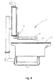
- the apparatus further comprises a fixation device 3, the details of which are shown in figure 4 .
- a set of intestines to be cut off is spread out on the charge surface 2, while it is conveyed below a movable upper part 12 of the fixation device 3, and when the set of intestines is arranged correctly, the movable upper part 12 of the fixation device 3 is activated to fixate the intestines against a stationary lower part 11 of the fixation device 3.
- The, movable upper part 12 may be activated by activating an actuator, such as a pressure device 16, thus providing a semi-automated fixation of the intestines.
- the fixation may be activated in other ways, e.g. fully automated, e.g. by sensors being activated by the presence the intestines in the correct position.
- the movable upper part 12 of the fixation device 3 moves downwards and retains the set of intestines between the movable upper part 12 and a fixed lower part 11, which is preferably a part of the charge surface 2 e.g. the edge 2' thereof facing the operator 28.
- the intestines may be fixated in other ways, e.g. by pushing the intestines under a brace (not shown) being formed along the edge 2' of the charge surface (charge space) 2.
- the cutting out procedure consists in that the small intestine 27 is cut through and separated manually at a distance of about 50 cm from the stomach end of the intestine, but it may be necessary to perform further cutting out, e.g. in case the ruffle fat is split.
- the apparatus 1 of the invention is provided with a rack 4.
- the rack 4 (or movable rack 4) is mounted on a stationary rack 14.
- the stationary rack 14 is located behind the operator 28 (see Fig. 8 ), if the charge surface is defined as being in the front.
- the rack 4 extends forward from the stationary rack 14, towards the fixation device 3, and substantially at a right angle to the edge 2' of the charge surface 2.
- the rack 4 is movable towards/away from the fixation device 3 by means of an actuator 25, which may be a hydraulic or pneumatic device, e.g. an air servo.
- a cutter head 5 is provided on said movable rack 4, (the details will appear most clearly from figures 2 and 3 ), on a free end opposite the end mounted on stationary rack 14.
- the cutter head 5 comprises a number of jaws 6 (the details will appear most clearly from Figs. 6 and 7 , see further below).
- the stomach end of the small intestine 27 is conveyed from the fixation device 3 past the cutter head 5 to the effect that the ruffle fat is caused to enter between the jaws 6, while the small intestine 27 extends on the outside of the jaws 6.
- a pull-advance mechanism 9 is further provided comprising a first toothed wheel 17 with a guide plate 29. Following conveyance of the small intestine 27 past the cutter head 5 and on the outside of the jaws 6, the small intestine 27 is subsequently arranged on the guide plate 29 on the first toothed wheel 17, following which the cutting-off procedure starts.
- the guide plate 29 ensures that the small intestine is correctly inserted into the pull-advance mechanism 9.
- a discharger mechanism 10 is further provided serving the purpose of conveying the small intestine 27 from the pull-advance mechanism 9 to one of two discharge passages 26, which are where the cut-off small intestines 27 exit the apparatus 1.
- the discharger mechanism 10 is formed by a funnel extending from the back of the apparatus 1, with and outlet into the discharge passage 26, towards the fixation device 3, and arranged substantially in parallel with the rack 4.
- the discharger mechanism 10 has an inlet opening facing towards the pull-advance mechanism 9.
- the discharger mechanism 10 When about half of the small intestine 27 has travelled through the pull-advance mechanism 9, the discharger mechanism 10, having a pivotal stud or spout (not shown) at the outlet end, will change position to the effect that the pivotal stud or spout switches from the one discharge passage 26 to the other discharge passage 26, meaning that the two halves of the small intestine 27 are caused to enter into each their discharge passage 26.
- a length counter (not shown) arranged on the pull-advance mechanism 9 (based e.g. on the number of rotations of the wheel 17).
- a large-intestine rake perforates the ruffle fat being behind the fixation device 3 (as seen relative to the charge surface 2).
- This may be a manual function or a semi- or a fully automated function, and the rake moves away from the operator 28 to the effect that the rake tears the large intestine off the ruffle fat.
- the part of the set of intestines that comprises the large intestine is conveyed down onto a belt below the charge surface 2, and when the fixation device 3 opens to release the small intestine, the ruffle fat is sucked away through a slot (not shown) in a tray in front of the charge surface 2.
- Figure 2 shows the movable rack 4 in a preferred embodiment as a telescopic arm 15 which e.g. may be servo-controlled.
- the telescopic arm 15 is capable of moving the cutter head 5 away from and toward the stationary rack 14 and from side to side. The side to side movement may be necessary in order to be able to locate the cutter head 5 correctly relative to the small intestine 27.
- the telescopic arm 15 has an elongate axis A.
- the elongate axis A preferably is formed in an angle relative to a horizontal plane, such that arm 15 has a lower end where it is connected to stationary rack 14, and such that other end with the cutter head is located above the level where it the arm 15 is connected to the stationary rack 14.
- a non right-angled, thus oblique angle of the telescopic arm 15 in respect of the charge surface (horizontal plane) enables a simultaneous movement in the vertical plane as well as in the horizontal plane.
- the side to side movement of the arm 15 (with the cutter head 5) is provided by the arm 15 being rotationally connected to the stationary rack 14, about a vertically oriented axis B.
- the rotational motion is preferably controlled by another servo mechanism, e.g. an air servo.
- the telescopic arm 15 is under constant super-atmospheric pressure in order to keep the internal components dry.
- the actuator 25 that moves the telescopic arm 15 is arranged in the lowermost part of the movable rack 4, i.e. the part closest to the stationary rack 14.
- the movable rack 4 also serves as base for a pull-advance system 9 shown in figures 1 and 8 , and it controls a supply of water through the rack 4 to faces in contact with small intestines, i.e. especially the rotatable cutter and the jaws 6.
- Figure 3 shows the cutter head 5 that comprises a set of releasable jaws 6 (the details are shown in Figs. 6 and 7 ), wherein the jaws 6 convey the small intestine 27 past a rotating cutter 31 in the cutter head 5.
- sensors (not shown) are provided that are capable of detecting differences in the light refraction when it passes through fat/intestine.
- the sensors are connected to a control unit (not shown), and in this way the control unit is capable of determining the location of the interface between fat and intestine, based on signals from the sensors, and thereby to control the operation of the cutter head 5.
- the signals from the sensors are used to control the movement of the cutter head 5 back and forth via the movable rack 4.
- the jaws 6 are releasable from the cutter head 5 and adjustably formed therein.
- An adjustable gap 6' is formed between the jaws 6.
- the size of the gap 6' located between the jaws 6 being of decisive significance to the functioning of the apparatus 1 and which therefore needs to be checked at regular intervals.
- the distance should be about 1 to 1.5 mm, e.g. about 1.2 mm and, at the top, distant from the small intestine location 27, the distance should be about 0.8 to 1 mm, e.g. about 0.9 mm, in order for the cutter head 5 to function optimally.
- a removable lid 32 is provided on the undersurface or lower surface of the cutter head 5, meaning in this context the side where the jaws 6 are arranged.
- the lid 32 serves the dual purpose of protecting against inadvertent contact with the knife 31 of the cutter head 5 and ensuring that water can hit both the knife 31 of the cutter head 5 and the small intestine 27.
- Water serves a lubricating function when the apparatus is operating, and ensures that the fat slides freely through the gap 6' located between the jaws 6.
- Water is supplied via not shown nozzles in cutter head 5.
- the removable lid 32 also makes sure that the water hits and washes the knife 31, and thereby prevents fat deposits from accumulating on the blade of the knife 31.
- a motor 22 is provided, and the motor 22 may, e.g. by means of a belt drive, drive the knife of the cutter head 5 which is, in one embodiment, of the rotating kind, i.e. a rotating cutter 31 as shown in Fig 7 .
- the construction of the cutter head 5 makes it possible to cut off the ruffle fat at a more accurate distance from the small intestine 27 and so close to the small intestine 27 that shreds and the like are minimised. Besides, a longer average length of the end product of small intestines 27 is accomplished.
- FIG 4 shows the fixation device 3 in greater detail than in Figs 1 or 8 .
- the fixation device 3 comprises a fixed lower part 11 and a movable upper part 12, wherein, on the side of the movable upper part 12 that is intended for facing towards the fixed lower part 11, serrations 13 may be provided in some embodiments.
- the fixation device 3 functions in that the operator 28 (not shown) actuates the semi-automated pressure device 16 which, in one embodiment, is located in immediate succession of the fixed end of the movable upper part 12, thereby achieving better fixation.
- the fixation device 3 opens automatically as will be described in further detail below in the context of figure 5 .
- the pull-advance mechanism 9 comprises one or more wheels 17, 18.
- Figure 5 shows one embodiment of the pull-advance mechanism 9 having two wheels 17, 18.
- the pull-advance mechanism 9 is shown without a shield/cover.
- the wheels 17, 18 are mounted, a bracket 30.
- the wheels preferably, and as shown in Fig. 5 , comprises a first cylindrical toothed wheel 17 with external toothing and a second cylindrical toothed wheel 18 - also with external toothing.
- a pull-advance mechanism 9 with two wheels provides a more even pull and also provide a more compact mechanism.
- the pull-advance mechanism 9 may comprise only one wheel.
- the wheel or wheels may not be toothed. Instead they may be provided with suitable surface properties to advance the small intestine, e.g. a grating.
- the pull-advance mechanism 9 may have means (not shown) for regulating the centre-to-centre distance between the two toothed wheels 17, 18 (i.e. the distance between the parallel rotation axes of the wheels 17, 18) that enables setting and adjustment of the centre-to-centre distance between the first toothed wheel 17 and the second toothed wheel 18.
- the pull-advance mechanism 9 may also function without such means for regulating the centre-to-centre distance between the two toothed wheels 17, 18, but in that case it is inherently not possible to set and adjust the centre-to-centre distance between the first toothed wheel 17 and the second toothed wheel 18.
- the centre-to-centre distance between the first toothed wheel 17 and the second toothed wheel 18 is closer to the largest possible centre-to-centre distance having the smallest possible degree of engagement/profile overlap than the theoretically smallest possible centre-to-centre distance between the first toothed wheel 17 and the second toothed wheel 18 having the largest possible degree of engagement.
- a larger centre-to-centre distance and hence a smaller degree of engagement minimises the risk of the small intestines 27 being damaged.
- a motor 19, is also mounted on the bracket 30.
- the motor 19 drives the pull-advance mechanism 9.
- the motor 19 may be either directly connected to the first toothed wheel 17, or the motor 19 may be indirectly connected to the first toothed wheel 17, e.g. by means of a toothed gearing.
- the second toothed wheel 18 may be arranged to be free running. Thereby it may be driven by the first toothed wheel 17. Irrespective of the way in which the motor 19 and the first toothed wheel 17 are connected, it entails that the first toothed wheel 17 becomes the driving toothed wheel of the pull-advance mechanism 9. The second toothed wheel 18 thereby becomes the following toothed wheel, driven by the first toothed wheel 17. In some embodiments the first toothed wheel 17 could acts as the following toothed wheel driven by the second toothed wheel 18. In yet other embodiments both wheels may be driven by suitable gearing.
- the axis (rotational axis) of the first toothed wheel 17 and the axis (rotational axis) of the second toothed wheel 18 are arranged in parallel to each other.
- the first toothed wheel 17 and the second toothed wheel 18 thus have a mutual and uniform engagement. The engagement will thus remain unchanged, no matter how the toothed wheels are located relative to each other and irrespective of the number of toothed wheel revolutions.
- the first toothed wheel 17 and the second toothed wheel 18 being in one embodiment straight-toothed toothed wheels, a uniform engagement is thus also ensured across the entire tooth width for the entire engagement of the tooth profile.
- the first toothed wheel 17 and the second toothed wheel 18 has different tooth profiles.
- the tooth profile of the first toothed wheel 17 has a pitch where the period to amplitude ratio is higher than that of the tooth profile of the second toothed wheel 18.
- the radius of curvature of the first tooth wheel's 17 tooth shape thereby also becomes smaller than the radius of curvature of the second tooth wheel's 17 tooth shape, whereby the system is evenly locked.
- the pull-advance mechanism 9 may have a brake (not shown) connected to the second toothed wheel 18 which may ensure friction and hence the retainment of the elongate soft-tissue parts between the first toothed wheel 17 and the second toothed wheel 18 is provided.
- a brake (not shown) connected to the second toothed wheel 18 which may ensure friction and hence the retainment of the elongate soft-tissue parts between the first toothed wheel 17 and the second toothed wheel 18 is provided.
- Such braking device may, in particular in case of a large centre-to-centre distance between the first toothed wheel 17 and the second toothed wheel 18, be adequate to ensure that the small intestines 27 are pulled forwards.
- a friction-creating surface structure on the surfaces of the toothed wheels.
- Such friction-creating surface structure could e.g. be a knurling on both the first toothed wheel 17 and the second toothed wheel 18.
- the friction-creating surface structure should be on the second toothed wheel 18 when it is the toothed wheel which is not driven and hence has a braking function.
- the first toothed wheel 17 and the second toothed wheel 18 have been found to have a suitable size on the one hand in respect of the operation of the pull-advance mechanism 9 and, on the other, in respect of the space occupied by the pull-advance mechanism 9 on the site of use.
- first toothed wheel 17 and the second toothed wheel 18 have the same external diameter and the same number of teeth selected as a number of teeth of 5 - 13, such as 7 - 11, e.g. 9, function optimally in use.
- the pull-advance mechanism 9 provides the option of many possible combinations within the given intervals, where it will be possible e.g. to scale the diameters to a desired dimension. However, it will be obvious to a person skilled in the art that there are combination options outside these intervals.
- a guide shield 29 (also called guide plate 29) is provided on one side of the first toothed wheel 17.
- the guide shield 29 is in the form of a plate having the shape of a conical surface, and with an axis that coincides with the axis of the toothed wheel 17.
- the guide shield 29 is adapted for guiding the small intestine towards the tooth wheel 17.
- the guide shield 29 has a half apex angle in relation to the axis of the wheel 17 of about 20° - 40°, such as about 25° - 35°, and e.g. about 30°.
- a trigger (not shown) is mounted on the second toothed wheel 18, the trigger enabling a revolution sensor (not shown) mounted on the bracket 30 to register the number of revolutions of the second toothed wheel 18.
- a counter/revolution sensor (not shown) begins to count revolutions on the second toothed wheel 18 in the pull-advance mechanism 9.
- the discharger mechanism 10 changes position to the effect that the intestine 27 is conveyed into the second discharge passage 26.
- the fixation device 3 When the motor 19 is no longer loaded and the predetermined length of small intestine 27 has been reached, the fixation device 3 will open.
- Figure 6 shows the jaws 6 of the cutter head 5 in one embodiment of the invention, wherein, between the jaws 6, there is a gap with a distance in the inlet 6" of about 1-1.5 mm, e.g. about 1.2 mm and a distance in the outlet 6"' of about 0.8-1 mm, e.g. about 0.9 mm.
- the front side of the jaws controls the movement of the intestine during and after the cutting-off procedure.
- the rear side controls the movement of the fat following the cutting-off procedure.
- the jaws control the distance from the intestines at which the fat is cut away.
- Fig. 7 shows how the jaws and a knife in the form of a rotating cutter 31 is interrelated to cut fat from the small intestine 27.
- Figure 8 shows a cutting-off station 23 having two apparatus 1 according to the invention.
- the cutting-off station 23 comprises an operator platform 24 arranged between the two apparatuses 1.
- the platform 24 is adjustable in height such that an optimal distance from the charge surface may be obtained, and such that an ergonomic relation is obtained between the charge surface 2 and the forearm of the operator 28.
- the construction of the cutting-off station 23 with two mirrored apparatuses 1 to each side of the operator's 28 work space makes it possible for the operator 28 to operate two apparatuses alternately.
Landscapes
- Life Sciences & Earth Sciences (AREA)
- Engineering & Computer Science (AREA)
- Wood Science & Technology (AREA)
- Zoology (AREA)
- Food Science & Technology (AREA)
- Endoscopes (AREA)
Claims (16)
- Appareil (1) de sectionnement d'intestin grêle (27) d'un ensemble isolé et non traité d'intestins et d'estomac d'un mammifère, l'appareil (1) comprenant :- une surface de charge (2) ;- un dispositif de fixation (3) agencé au niveau d'un bord (2') de ladite surface de charge (2) et destiné à fixer une première extrémité d'un intestin grêle (27) ;- un mécanisme de déchargement (10) ;- un mécanisme d'avancement par traction (9) pour tirer, depuis une position au niveau du dispositif de fixation (3), une seconde extrémité libre d'un intestin grêle vers le mécanisme de déchargement (10) ;- et une tête de découpe (5), dans lequel la tête de découpe (5) et ledit mécanisme d'avancement par traction (9) sont prévus sur un châssis (4), de sorte que ladite tête de découpe (5) soit mobile au moins dans une direction s'approchant/s'éloignant du dispositif de fixation (3).
- Appareil (1) selon la revendication 1, dans lequel ladite tête de découpe (5) comprend une paire de mâchoires (6) et un couteau rotatif.
- Appareil (1) selon la revendication 1 ou 2, dans lequel ledit dispositif de fixation (3) comprend une partie inférieure stationnaire (11) et une partie supérieure mobile (12) coopérant avec la partie inférieure (11) et un actionneur destiné à presser la partie supérieure mobile (12) vers la partie inférieure (11).
- Appareil selon la revendication 3, dans lequel des dentelures (13) sont prévues sur ladite partie supérieure mobile (12) sur une partie faisant face à ladite partie inférieure stationnaire (11).
- Appareil selon l'une quelconque des revendications 1 à 4, dans lequel ledit châssis mobile (4) comprend un bras (15) agencé de façon sensiblement perpendiculaire au dispositif de fixation (3), ladite tête de découpe (5) étant agencée au niveau d'une extrémité dudit bras (15).
- Appareil selon l'une quelconque des revendications 1 à 6, dans lequel ledit dispositif de fixation (3) est équipé d'un couteau pour désolidariser l'intestin grêle (27) de l'estomac.
- Appareil selon l'une quelconque des revendications 1 à 6, dans lequel ladite tête de découpe (5) peut être déplacée pour s'approcher/s'éloigner dudit dispositif de fixation (3) par un moyen automatique ou semi-automatique.
- Appareil selon la revendication 7, dans lequel ledit châssis mobile (4) est un bras télescopique (15) qui peut être déplacé par un actionneur (25) et dans lequel le bras télescopique (15) est monté sur un châssis stationnaire.
- Appareil selon la revendication 8, dans lequel ledit bras télescopique (15) est incliné par rapport à l'horizontale et son extrémité libre est la plus haute et la plus proche du dispositif de fixation (3).
- Appareil selon la revendication 8 ou 9, dans lequel le bras télescopique (15) peut tourner autour d'un axe sensiblement vertical du châssis stationnaire.
- Appareil selon l'une quelconque des revendications 1 à 10, dans lequel ledit mécanisme d'avancement par traction (9) comprend deux roues dentées (17, 18) avec des axes de rotation parallèles, lesdites roues dentées (17, 18) étant en prise l'une avec l'autre et dans lequel la première roue dentée (17) est entraînée par un moteur (19) et dans lequel la seconde roue dentée (18) tourne librement ou inversement.
- Appareil selon l'une quelconque des revendications 2 à 11, dans lequel il existe un espace (6') entre lesdites mâchoires (6) avec une distance dans l'entrée (6") d'environ 1-1,5 mm, par ex. environ 1,2 mm et une distance dans la sortie (6"') d'environ 0,8-1 mm, par ex. environ 0,9 mm.
- Appareil selon l'une quelconque des revendications 1 à 12, comprenant en outre un râteau pour gros intestin (20) agencé sur le côté opposé du dispositif de fixation (3) observé par rapport au châssis mobile (4).
- Poste de sectionnement (23) comprenant au moins deux appareils (1) selon l'une quelconque des revendications 1 à 13, dans lequel ledit poste de sectionnement (23) comprend une plateforme d'opérateur (24) et dans lequel le châssis (4) et les mécanismes d'avancement par traction (9) sont symétriquement opposés sur les deux côtés de ladite plateforme d'opérateur (24).
- Utilisation d'un appareil (1) selon l'une quelconque des revendications 1 à 12 pour le traitement et la mesure de parties de tissus mous, telles que les intestins grêles (jéjunum et iléon) de mammifères.
- Procédé de sectionnement et de traitement d'intestins grêles (jéjunum et iléon) d'un ensemble isolé et non traité d'intestins et d'estomac d'un mammifère, comprenant les étapes consistant àa) agencer l'ensemble d'intestins à sectionner et traiter au niveau de la surface de charge (2) d'un appareil (1) selon l'une quelconque des revendications 1 à 13, de manière telle que l'ensemble d'intestins soit tiré sur le bord de la surface de charge (2) et au-delà de celui-ci, dans une mesure telle que l'intestin grêle (27) fasse face vers un opérateur (28) de l'appareil (1) et que l'extrémité côté estomac fasse face à l'opposé dudit opérateur (28),b) transporter l'ensemble d'intestins sous une partie supérieure mobile (12) d'un dispositif de fixation (3) dudit appareil (1) et actionner, lorsque l'ensemble d'intestins est déployé correctement, la partie supérieure mobile (12) afin de fixer ladite extrémité côté estomac de l'intestin grêle (27) contre une partie inférieure (11) dudit dispositif de fixation (3),c) sectionner et séparer ledit intestin grêle (27) de l'extrémité côté estomac de l'intestin,d) transporter une extrémité libre de l'intestin grêle (27) depuis ledit dispositif de fixation (3) en passant devant une tête de découpe (5) dudit appareil (1) jusqu'à un mécanisme d'avancement par traction (9) de l'appareil (1), moyennant quoi la procédure de sectionnement est démarrée ete) transporter l'extrémité libre de l'intestin grêle sectionné vers un mécanisme de déchargement (10) dudit appareil (1).
Priority Applications (1)
| Application Number | Priority Date | Filing Date | Title |
|---|---|---|---|
| EP14705165.0A EP2956009B1 (fr) | 2013-02-18 | 2014-02-18 | Appareil et procédé pour sectionnement d'intestin grêle |
Applications Claiming Priority (3)
| Application Number | Priority Date | Filing Date | Title |
|---|---|---|---|
| EP13155656 | 2013-02-18 | ||
| EP14705165.0A EP2956009B1 (fr) | 2013-02-18 | 2014-02-18 | Appareil et procédé pour sectionnement d'intestin grêle |
| PCT/EP2014/053105 WO2014125118A1 (fr) | 2013-02-18 | 2014-02-18 | Appareil et procédé pour séparer les intestins grêles |
Publications (2)
| Publication Number | Publication Date |
|---|---|
| EP2956009A1 EP2956009A1 (fr) | 2015-12-23 |
| EP2956009B1 true EP2956009B1 (fr) | 2016-09-14 |
Family
ID=47722128
Family Applications (1)
| Application Number | Title | Priority Date | Filing Date |
|---|---|---|---|
| EP14705165.0A Active EP2956009B1 (fr) | 2013-02-18 | 2014-02-18 | Appareil et procédé pour sectionnement d'intestin grêle |
Country Status (3)
| Country | Link |
|---|---|
| US (1) | US20160021901A1 (fr) |
| EP (1) | EP2956009B1 (fr) |
| WO (1) | WO2014125118A1 (fr) |
Families Citing this family (1)
| Publication number | Priority date | Publication date | Assignee | Title |
|---|---|---|---|---|
| DK182008B1 (en) * | 2024-07-03 | 2025-05-26 | Dat Schaub As | A knife, a system and a method for separating a small intestines from a bowel package of an animal carcass |
Family Cites Families (10)
| Publication number | Priority date | Publication date | Assignee | Title |
|---|---|---|---|---|
| US2239199A (en) * | 1936-10-06 | 1941-04-22 | Ind Patents Corp | Casing machine |
| US4073040A (en) * | 1975-08-13 | 1978-02-14 | Hill Carl J | Machine for process of poultry gizzards |
| US4063331A (en) * | 1976-05-24 | 1977-12-20 | Wilson Foods Corporation | Gut puller |
| US4245372A (en) * | 1979-01-22 | 1981-01-20 | Campbell Soup Company | Apparatus for processing of poultry |
| US5041053A (en) * | 1990-08-01 | 1991-08-20 | Cantrell Machine Company, Inc. | Heart harvesting system and method |
| US5186678A (en) * | 1990-08-01 | 1993-02-16 | Cantrell Machine Company, Inc. | Heart and liver harvesting system |
| NL9101856A (nl) * | 1991-11-07 | 1993-06-01 | Meyn Maschf | Werkwijze en inrichting voor het in losse onderdelen scheiden van een uit een vogel verwijderd pakket bestaande uit darmen, lever en hart met longen. |
| NL9300815A (nl) * | 1992-09-10 | 1994-04-05 | Stork Pmt | Werkwijze en inrichting voor het verwijderen en verwerken van een organenpakket van een slachtdier. |
| NL1006580C2 (nl) * | 1997-07-14 | 1999-01-15 | Stork Pmt | Werkwijze en inrichting voor het verwerken van geslacht gevogelte, alsmede transportorgaan voor toepassing in een dergelijke werkwijze en inrichting. |
| DE69833707T2 (de) * | 1997-09-29 | 2006-08-17 | Stork Pmt B.V. | Verfahren und Vorrichtung zum Verarbeiten von geschlachteten Geflügel vor dem Entfernen von Eingeweiden aus dem Vogel |
-
2014
- 2014-02-18 EP EP14705165.0A patent/EP2956009B1/fr active Active
- 2014-02-18 WO PCT/EP2014/053105 patent/WO2014125118A1/fr not_active Ceased
- 2014-02-18 US US14/766,876 patent/US20160021901A1/en not_active Abandoned
Also Published As
| Publication number | Publication date |
|---|---|
| WO2014125118A1 (fr) | 2014-08-21 |
| EP2956009A1 (fr) | 2015-12-23 |
| US20160021901A1 (en) | 2016-01-28 |
Similar Documents
| Publication | Publication Date | Title |
|---|---|---|
| ES2988901T3 (es) | Máquina para colocar productos alimenticios en rodajas en contenedores | |
| TWI445501B (zh) | 貝類固定及打開裝置與其方法 | |
| JPH08118288A (ja) | 2つ以上の食物の塊をスライスする装置及び方法 | |
| GB2440432A (en) | Dual mode feed mechanism for a food slicing machine | |
| US5217404A (en) | Process for the calibration, length measurement and packaging of portions of intestine used in pork butchery and apparatus for carrying it out | |
| EP2522225A1 (fr) | Machine à couper de la viande, en particulier pour la coupe de la viande avec os | |
| EP3183970A1 (fr) | Machine de découpage avec accès facile | |
| CN104754948B (zh) | 用于对输送机上的鸟进行处理的方法和装置 | |
| SE502500C2 (sv) | Sätt och anordning för avlägsnande av skinnet från en korv | |
| CN109397384A (zh) | 一种板材加工自动分切分料设备 | |
| EP2956009B1 (fr) | Appareil et procédé pour sectionnement d'intestin grêle | |
| NZ226714A (en) | Poultry skinning apparatus | |
| US9895820B2 (en) | Bread slicing machine having an advancing device | |
| CN105638840B (zh) | 用以收集并填充的分离驱动装置 | |
| EP2759205A1 (fr) | Dispositif de coupe servant à couper de la viande en portions requises | |
| JP7835995B2 (ja) | 散薬包装装置 | |
| RU2737673C1 (ru) | Клипсатор с усовершенствованным выгружающим устройством | |
| CN206616398U (zh) | 开幅验布机的切刀机构及开幅验布机 | |
| JPH0484850A (ja) | 食肉の脂肪層自動計測装置 | |
| JPH0742314Y2 (ja) | 魚解体装置 | |
| EP3001908A1 (fr) | Unités d'entraînement découplées pour rassembler et répandre | |
| JP4649579B2 (ja) | 食肉スライサーの運転方法 | |
| KR102259812B1 (ko) | 골절기의 절단 안전장치 | |
| JP2015517920A (ja) | 被印刷基材用切断装置 | |
| CN119234863B (zh) | 一种ai智能柔性开嗉囊工艺方法 |
Legal Events
| Date | Code | Title | Description |
|---|---|---|---|
| PUAI | Public reference made under article 153(3) epc to a published international application that has entered the european phase |
Free format text: ORIGINAL CODE: 0009012 |
|
| 17P | Request for examination filed |
Effective date: 20150825 |
|
| AK | Designated contracting states |
Kind code of ref document: A1 Designated state(s): AL AT BE BG CH CY CZ DE DK EE ES FI FR GB GR HR HU IE IS IT LI LT LU LV MC MK MT NL NO PL PT RO RS SE SI SK SM TR |
|
| AX | Request for extension of the european patent |
Extension state: BA ME |
|
| GRAP | Despatch of communication of intention to grant a patent |
Free format text: ORIGINAL CODE: EPIDOSNIGR1 |
|
| INTG | Intention to grant announced |
Effective date: 20160408 |
|
| GRAS | Grant fee paid |
Free format text: ORIGINAL CODE: EPIDOSNIGR3 |
|
| GRAA | (expected) grant |
Free format text: ORIGINAL CODE: 0009210 |
|
| AK | Designated contracting states |
Kind code of ref document: B1 Designated state(s): AL AT BE BG CH CY CZ DE DK EE ES FI FR GB GR HR HU IE IS IT LI LT LU LV MC MK MT NL NO PL PT RO RS SE SI SK SM TR |
|
| AX | Request for extension of the european patent |
Extension state: BA ME |
|
| REG | Reference to a national code |
Ref country code: GB Ref legal event code: FG4D |
|
| REG | Reference to a national code |
Ref country code: CH Ref legal event code: EP |
|
| REG | Reference to a national code |
Ref country code: IE Ref legal event code: FG4D |
|
| REG | Reference to a national code |
Ref country code: AT Ref legal event code: REF Ref document number: 827899 Country of ref document: AT Kind code of ref document: T Effective date: 20161015 |
|
| REG | Reference to a national code |
Ref country code: DE Ref legal event code: R096 Ref document number: 602014003673 Country of ref document: DE |
|
| REG | Reference to a national code |
Ref country code: LT Ref legal event code: MG4D |
|
| REG | Reference to a national code |
Ref country code: NL Ref legal event code: MP Effective date: 20160914 |
|
| PG25 | Lapsed in a contracting state [announced via postgrant information from national office to epo] |
Ref country code: HR Free format text: LAPSE BECAUSE OF FAILURE TO SUBMIT A TRANSLATION OF THE DESCRIPTION OR TO PAY THE FEE WITHIN THE PRESCRIBED TIME-LIMIT Effective date: 20160914 Ref country code: RS Free format text: LAPSE BECAUSE OF FAILURE TO SUBMIT A TRANSLATION OF THE DESCRIPTION OR TO PAY THE FEE WITHIN THE PRESCRIBED TIME-LIMIT Effective date: 20160914 Ref country code: LT Free format text: LAPSE BECAUSE OF FAILURE TO SUBMIT A TRANSLATION OF THE DESCRIPTION OR TO PAY THE FEE WITHIN THE PRESCRIBED TIME-LIMIT Effective date: 20160914 Ref country code: NO Free format text: LAPSE BECAUSE OF FAILURE TO SUBMIT A TRANSLATION OF THE DESCRIPTION OR TO PAY THE FEE WITHIN THE PRESCRIBED TIME-LIMIT Effective date: 20161214 Ref country code: FI Free format text: LAPSE BECAUSE OF FAILURE TO SUBMIT A TRANSLATION OF THE DESCRIPTION OR TO PAY THE FEE WITHIN THE PRESCRIBED TIME-LIMIT Effective date: 20160914 |
|
| REG | Reference to a national code |
Ref country code: AT Ref legal event code: MK05 Ref document number: 827899 Country of ref document: AT Kind code of ref document: T Effective date: 20160914 |
|
| PG25 | Lapsed in a contracting state [announced via postgrant information from national office to epo] |
Ref country code: LV Free format text: LAPSE BECAUSE OF FAILURE TO SUBMIT A TRANSLATION OF THE DESCRIPTION OR TO PAY THE FEE WITHIN THE PRESCRIBED TIME-LIMIT Effective date: 20160914 Ref country code: GR Free format text: LAPSE BECAUSE OF FAILURE TO SUBMIT A TRANSLATION OF THE DESCRIPTION OR TO PAY THE FEE WITHIN THE PRESCRIBED TIME-LIMIT Effective date: 20161215 Ref country code: SE Free format text: LAPSE BECAUSE OF FAILURE TO SUBMIT A TRANSLATION OF THE DESCRIPTION OR TO PAY THE FEE WITHIN THE PRESCRIBED TIME-LIMIT Effective date: 20160914 Ref country code: NL Free format text: LAPSE BECAUSE OF FAILURE TO SUBMIT A TRANSLATION OF THE DESCRIPTION OR TO PAY THE FEE WITHIN THE PRESCRIBED TIME-LIMIT Effective date: 20160914 |
|
| PG25 | Lapsed in a contracting state [announced via postgrant information from national office to epo] |
Ref country code: RO Free format text: LAPSE BECAUSE OF FAILURE TO SUBMIT A TRANSLATION OF THE DESCRIPTION OR TO PAY THE FEE WITHIN THE PRESCRIBED TIME-LIMIT Effective date: 20160914 Ref country code: EE Free format text: LAPSE BECAUSE OF FAILURE TO SUBMIT A TRANSLATION OF THE DESCRIPTION OR TO PAY THE FEE WITHIN THE PRESCRIBED TIME-LIMIT Effective date: 20160914 |
|
| PG25 | Lapsed in a contracting state [announced via postgrant information from national office to epo] |
Ref country code: AT Free format text: LAPSE BECAUSE OF FAILURE TO SUBMIT A TRANSLATION OF THE DESCRIPTION OR TO PAY THE FEE WITHIN THE PRESCRIBED TIME-LIMIT Effective date: 20160914 Ref country code: PT Free format text: LAPSE BECAUSE OF FAILURE TO SUBMIT A TRANSLATION OF THE DESCRIPTION OR TO PAY THE FEE WITHIN THE PRESCRIBED TIME-LIMIT Effective date: 20170116 Ref country code: BG Free format text: LAPSE BECAUSE OF FAILURE TO SUBMIT A TRANSLATION OF THE DESCRIPTION OR TO PAY THE FEE WITHIN THE PRESCRIBED TIME-LIMIT Effective date: 20161214 Ref country code: ES Free format text: LAPSE BECAUSE OF FAILURE TO SUBMIT A TRANSLATION OF THE DESCRIPTION OR TO PAY THE FEE WITHIN THE PRESCRIBED TIME-LIMIT Effective date: 20160914 Ref country code: BE Free format text: LAPSE BECAUSE OF FAILURE TO SUBMIT A TRANSLATION OF THE DESCRIPTION OR TO PAY THE FEE WITHIN THE PRESCRIBED TIME-LIMIT Effective date: 20160914 Ref country code: CZ Free format text: LAPSE BECAUSE OF FAILURE TO SUBMIT A TRANSLATION OF THE DESCRIPTION OR TO PAY THE FEE WITHIN THE PRESCRIBED TIME-LIMIT Effective date: 20160914 Ref country code: PL Free format text: LAPSE BECAUSE OF FAILURE TO SUBMIT A TRANSLATION OF THE DESCRIPTION OR TO PAY THE FEE WITHIN THE PRESCRIBED TIME-LIMIT Effective date: 20160914 Ref country code: IS Free format text: LAPSE BECAUSE OF FAILURE TO SUBMIT A TRANSLATION OF THE DESCRIPTION OR TO PAY THE FEE WITHIN THE PRESCRIBED TIME-LIMIT Effective date: 20170114 Ref country code: SK Free format text: LAPSE BECAUSE OF FAILURE TO SUBMIT A TRANSLATION OF THE DESCRIPTION OR TO PAY THE FEE WITHIN THE PRESCRIBED TIME-LIMIT Effective date: 20160914 Ref country code: SM Free format text: LAPSE BECAUSE OF FAILURE TO SUBMIT A TRANSLATION OF THE DESCRIPTION OR TO PAY THE FEE WITHIN THE PRESCRIBED TIME-LIMIT Effective date: 20160914 |
|
| REG | Reference to a national code |
Ref country code: DE Ref legal event code: R097 Ref document number: 602014003673 Country of ref document: DE |
|
| PG25 | Lapsed in a contracting state [announced via postgrant information from national office to epo] |
Ref country code: IT Free format text: LAPSE BECAUSE OF FAILURE TO SUBMIT A TRANSLATION OF THE DESCRIPTION OR TO PAY THE FEE WITHIN THE PRESCRIBED TIME-LIMIT Effective date: 20160914 |
|
| PLBE | No opposition filed within time limit |
Free format text: ORIGINAL CODE: 0009261 |
|
| STAA | Information on the status of an ep patent application or granted ep patent |
Free format text: STATUS: NO OPPOSITION FILED WITHIN TIME LIMIT |
|
| PG25 | Lapsed in a contracting state [announced via postgrant information from national office to epo] |
Ref country code: DK Free format text: LAPSE BECAUSE OF FAILURE TO SUBMIT A TRANSLATION OF THE DESCRIPTION OR TO PAY THE FEE WITHIN THE PRESCRIBED TIME-LIMIT Effective date: 20160914 |
|
| 26N | No opposition filed |
Effective date: 20170615 |
|
| REG | Reference to a national code |
Ref country code: DE Ref legal event code: R119 Ref document number: 602014003673 Country of ref document: DE |
|
| PG25 | Lapsed in a contracting state [announced via postgrant information from national office to epo] |
Ref country code: MC Free format text: LAPSE BECAUSE OF FAILURE TO SUBMIT A TRANSLATION OF THE DESCRIPTION OR TO PAY THE FEE WITHIN THE PRESCRIBED TIME-LIMIT Effective date: 20160914 |
|
| REG | Reference to a national code |
Ref country code: CH Ref legal event code: PL |
|
| PG25 | Lapsed in a contracting state [announced via postgrant information from national office to epo] |
Ref country code: CH Free format text: LAPSE BECAUSE OF NON-PAYMENT OF DUE FEES Effective date: 20170228 Ref country code: LI Free format text: LAPSE BECAUSE OF NON-PAYMENT OF DUE FEES Effective date: 20170228 |
|
| REG | Reference to a national code |
Ref country code: IE Ref legal event code: MM4A |
|
| PG25 | Lapsed in a contracting state [announced via postgrant information from national office to epo] |
Ref country code: SI Free format text: LAPSE BECAUSE OF FAILURE TO SUBMIT A TRANSLATION OF THE DESCRIPTION OR TO PAY THE FEE WITHIN THE PRESCRIBED TIME-LIMIT Effective date: 20160914 |
|
| REG | Reference to a national code |
Ref country code: FR Ref legal event code: ST Effective date: 20171031 |
|
| PG25 | Lapsed in a contracting state [announced via postgrant information from national office to epo] |
Ref country code: LU Free format text: LAPSE BECAUSE OF NON-PAYMENT OF DUE FEES Effective date: 20170218 |
|
| PG25 | Lapsed in a contracting state [announced via postgrant information from national office to epo] |
Ref country code: FR Free format text: LAPSE BECAUSE OF NON-PAYMENT OF DUE FEES Effective date: 20170228 Ref country code: DE Free format text: LAPSE BECAUSE OF NON-PAYMENT OF DUE FEES Effective date: 20170901 |
|
| PG25 | Lapsed in a contracting state [announced via postgrant information from national office to epo] |
Ref country code: IE Free format text: LAPSE BECAUSE OF NON-PAYMENT OF DUE FEES Effective date: 20170218 |
|
| PG25 | Lapsed in a contracting state [announced via postgrant information from national office to epo] |
Ref country code: MT Free format text: LAPSE BECAUSE OF NON-PAYMENT OF DUE FEES Effective date: 20170218 |
|
| GBPC | Gb: european patent ceased through non-payment of renewal fee |
Effective date: 20180218 |
|
| PG25 | Lapsed in a contracting state [announced via postgrant information from national office to epo] |
Ref country code: AL Free format text: LAPSE BECAUSE OF FAILURE TO SUBMIT A TRANSLATION OF THE DESCRIPTION OR TO PAY THE FEE WITHIN THE PRESCRIBED TIME-LIMIT Effective date: 20160914 |
|
| PG25 | Lapsed in a contracting state [announced via postgrant information from national office to epo] |
Ref country code: GB Free format text: LAPSE BECAUSE OF NON-PAYMENT OF DUE FEES Effective date: 20180218 |
|
| PG25 | Lapsed in a contracting state [announced via postgrant information from national office to epo] |
Ref country code: HU Free format text: LAPSE BECAUSE OF FAILURE TO SUBMIT A TRANSLATION OF THE DESCRIPTION OR TO PAY THE FEE WITHIN THE PRESCRIBED TIME-LIMIT; INVALID AB INITIO Effective date: 20140218 |
|
| PG25 | Lapsed in a contracting state [announced via postgrant information from national office to epo] |
Ref country code: CY Free format text: LAPSE BECAUSE OF FAILURE TO SUBMIT A TRANSLATION OF THE DESCRIPTION OR TO PAY THE FEE WITHIN THE PRESCRIBED TIME-LIMIT Effective date: 20160914 |
|
| PG25 | Lapsed in a contracting state [announced via postgrant information from national office to epo] |
Ref country code: MK Free format text: LAPSE BECAUSE OF FAILURE TO SUBMIT A TRANSLATION OF THE DESCRIPTION OR TO PAY THE FEE WITHIN THE PRESCRIBED TIME-LIMIT Effective date: 20160914 |
|
| PG25 | Lapsed in a contracting state [announced via postgrant information from national office to epo] |
Ref country code: TR Free format text: LAPSE BECAUSE OF FAILURE TO SUBMIT A TRANSLATION OF THE DESCRIPTION OR TO PAY THE FEE WITHIN THE PRESCRIBED TIME-LIMIT Effective date: 20160914 |