EP2956051B1 - Améliorations de la surveillance de l'activité cardiaque pendant un exercice physique - Google Patents
Améliorations de la surveillance de l'activité cardiaque pendant un exercice physique Download PDFInfo
- Publication number
- EP2956051B1 EP2956051B1 EP13709954.5A EP13709954A EP2956051B1 EP 2956051 B1 EP2956051 B1 EP 2956051B1 EP 13709954 A EP13709954 A EP 13709954A EP 2956051 B1 EP2956051 B1 EP 2956051B1
- Authority
- EP
- European Patent Office
- Prior art keywords
- heart activity
- phase
- activity measurement
- measurement signal
- qrs complex
- Prior art date
- Legal status (The legal status is an assumption and is not a legal conclusion. Google has not performed a legal analysis and makes no representation as to the accuracy of the status listed.)
- Active
Links
Images





Classifications
-
- A—HUMAN NECESSITIES
- A61—MEDICAL OR VETERINARY SCIENCE; HYGIENE
- A61B—DIAGNOSIS; SURGERY; IDENTIFICATION
- A61B5/00—Measuring for diagnostic purposes; Identification of persons
- A61B5/02—Detecting, measuring or recording for evaluating the cardiovascular system, e.g. pulse, heart rate, blood pressure or blood flow
- A61B5/024—Measuring pulse rate or heart rate
- A61B5/0245—Measuring pulse rate or heart rate by using sensing means generating electric signals, i.e. ECG signals
-
- A—HUMAN NECESSITIES
- A61—MEDICAL OR VETERINARY SCIENCE; HYGIENE
- A61B—DIAGNOSIS; SURGERY; IDENTIFICATION
- A61B5/00—Measuring for diagnostic purposes; Identification of persons
- A61B5/08—Measuring devices for evaluating the respiratory organs
- A61B5/0816—Measuring devices for examining respiratory frequency
-
- A—HUMAN NECESSITIES
- A61—MEDICAL OR VETERINARY SCIENCE; HYGIENE
- A61B—DIAGNOSIS; SURGERY; IDENTIFICATION
- A61B5/00—Measuring for diagnostic purposes; Identification of persons
- A61B5/24—Detecting, measuring or recording bioelectric or biomagnetic signals of the body or parts thereof
- A61B5/316—Modalities, i.e. specific diagnostic methods
- A61B5/318—Heart-related electrical modalities, e.g. electrocardiography [ECG]
- A61B5/346—Analysis of electrocardiograms
- A61B5/349—Detecting specific parameters of the electrocardiograph cycle
-
- A—HUMAN NECESSITIES
- A61—MEDICAL OR VETERINARY SCIENCE; HYGIENE
- A61B—DIAGNOSIS; SURGERY; IDENTIFICATION
- A61B5/00—Measuring for diagnostic purposes; Identification of persons
- A61B5/24—Detecting, measuring or recording bioelectric or biomagnetic signals of the body or parts thereof
- A61B5/316—Modalities, i.e. specific diagnostic methods
- A61B5/318—Heart-related electrical modalities, e.g. electrocardiography [ECG]
- A61B5/346—Analysis of electrocardiograms
- A61B5/349—Detecting specific parameters of the electrocardiograph cycle
- A61B5/352—Detecting R peaks, e.g. for synchronising diagnostic apparatus; Estimating R-R interval
-
- A—HUMAN NECESSITIES
- A61—MEDICAL OR VETERINARY SCIENCE; HYGIENE
- A61B—DIAGNOSIS; SURGERY; IDENTIFICATION
- A61B5/00—Measuring for diagnostic purposes; Identification of persons
- A61B5/68—Arrangements of detecting, measuring or recording means, e.g. sensors, in relation to patient
- A61B5/6801—Arrangements of detecting, measuring or recording means, e.g. sensors, in relation to patient specially adapted to be attached to or worn on the body surface
- A61B5/6813—Specially adapted to be attached to a specific body part
- A61B5/6823—Trunk, e.g., chest, back, abdomen, hip
-
- A—HUMAN NECESSITIES
- A61—MEDICAL OR VETERINARY SCIENCE; HYGIENE
- A61B—DIAGNOSIS; SURGERY; IDENTIFICATION
- A61B5/00—Measuring for diagnostic purposes; Identification of persons
- A61B5/72—Signal processing specially adapted for physiological signals or for diagnostic purposes
- A61B5/7203—Signal processing specially adapted for physiological signals or for diagnostic purposes for noise prevention, reduction or removal
-
- A—HUMAN NECESSITIES
- A61—MEDICAL OR VETERINARY SCIENCE; HYGIENE
- A61B—DIAGNOSIS; SURGERY; IDENTIFICATION
- A61B5/00—Measuring for diagnostic purposes; Identification of persons
- A61B5/72—Signal processing specially adapted for physiological signals or for diagnostic purposes
- A61B5/7235—Details of waveform analysis
- A61B5/7253—Details of waveform analysis characterised by using transforms
- A61B5/726—Details of waveform analysis characterised by using transforms using Wavelet transforms
Definitions
- the invention relates to the field of training devices and, particularly to training devices monitoring heart activity of a user during a physical exercise.
- Such training devices typically comprise electrodes that are placed into contact with the user's skin, and they measure a heart activity signal such as an electrocardiogram (ECG) signal non-invasively from the user's skin by using electric sensors, for example.
- ECG electrocardiogram
- US 2005/0222513 A1 discloses methods for quantifying the morphology and amplitude of cardio action potential alternans.
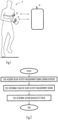
- Figure 1 illustrates a personal training system comprising a sensor device 10 configured to measure heart activity signals from a user's 11 body.
- the sensor device 10 may comprise one or a plurality of skin electrodes coupled to the user's 11 skin.
- the sensor device 10 may be based on detection of an electrocardiogram (ECG) signal from the user's 11 skin.
- ECG electrocardiogram
- the heart activity measurement signals measured from the user's body may comprise the ECG signal being detected and, possibly, noise and interference components.
- the sensor device 10 may further comprise a wireless communication circuitry configured to transmit measured heart activity measurement signals to another device, e.g. a user interface device 12, 14.
- the user interface device 12, 14 may be configured to process the received heart activity measurement signals and to illustrate training processed from the heart activity measurement signals to the user 11 via a display unit, for example.
- the user interface unit device a wrist device 12.
- the user interface device is a portable computer 14 such as a mobile phone or a tablet computer.
- Embodiments of the invention relate to monitoring properties of the heart activity measurement signals measured from the user's 11 skin.
- the embodiments may be carried out in any one of the above-described devices 10, 12, 14 or in any other device acquiring the heart activity measurement signals.
- the devices 10, 12, 14 may collectively be referred to as exercise monitoring apparatuses.
- FIG. 2 illustrates a method for processing a heart activity measurement signal in such an exercise monitoring apparatus.
- the heart activity measurement signal of a user 11 is acquired during a physical exercise performed by the user in block 200.
- the heart activity measurement signal is measured by at least one electrode in contact with the user 11.
- the heart activity measurement signal may be acquired directly from said at least one electrode.
- the heart activity measurement signal may be acquired wirelessly from the sensor device or from an internal sensor comprised in the user interface device 12, 14 and attached to the user 11.
- a phase of the heart activity measurement signal is monitored.
- a phase component of the heart activity measurement signal may be extracted from the received heart activity measurement signal as described below, for example.
- the phase of the heart activity measurement signal carries various information that may be used in improving the performance of the heart activity monitoring or even in determining other physiological parameters of the user 11.
- an action to be performed is determined on the basis of the phase of the heart activity measurement signal, and said action is carried out.
- the action comprises is an output of an instruction to be provided to the user via a user interface.
- the action comprises eliminating interfering signal components from further processing of the heart activity measurement signal.
- the action comprises determining a physiological parameter of the user other than heart activity or heart rate.
- the action comprises correcting measurement inaccuracies in the heart activity monitoring.
- the action comprises selecting a measurement configuration.
- the acquired heart activity measurement signal may be processed into a complex form by generating an in-phase (I) component and a quadrature (Q) component of the heart activity measurement signal, wherein a phase shift is provided between the I component and the Q component, as known in the art of signal processing.
- the I and Q components of the heart activity measurement signal may then be processed with a wavelet transform 300.
- a wavelet used as a basis for the wavelet transform may be selected according to design requirements by taking into account processing capabilities, for example.
- the wavelet is designed to have a bandwidth which is equal to or higher than a bandwidth of the heart activity measurement signal.
- the wavelet may be a Hanning wavelet, for example.
- the wavelet transform may be approximated with a low pass filter designed according to the characteristics of the selected wavelet.
- the phase of the heart activity measurement signal may be computed from the wavelet-transformed signal comprising the I and Q components by computing an argument of the signal (block 304).
- the computation of the argument may utilize arctangent function, as known in the art of signal processing.
- a phase component of the heart activity measurement signal is provided as an output of the argument computation in block 304.
- amplitude or power characteristics of the heart activity measurement signal may be monitored by computing a second norm of the heart activity measurement signal.
- the second norm also known as an Euclidean norm, may be computed by squaring the wavelet-transformed I and Q components of the heart activity measurement signal in block 302 and summing the squared I and Q components in block 306.
- the amplitude characteristics may be used in computation of a heart rate or R-R intervals of the heart activity measurement signal.
- An R-R interval refers to a time interval between consecutive R-wave components in the heart activity measurement signal.
- FIG. 4 illustrates a phase diagram, wherein a QRS complex waveform has been illustrated in connection with phase shifts between 0 and 360 degrees.
- phase shifts of 0 and 180 degrees result in an R wave having the highest amplitude.
- the amplitude of the R wave decreases and the amplitude of an S wave increases.
- the amplitude of the R wave decreases and the amplitude of a Q wave increases.
- the absolute value of the amplitude of the R wave again increases, and the QRS complex waveform with the phase shift of 180 degrees is a mirror image of the QRS complex waveform with the phase shift of 0 degrees. It can be deduced that a phase shift of 0 and 180 degrees provide the strongest R wave.
- Many heart activity detection procedures rely on detection of the R wave and, therefore, it is advantageous to provide a heart activity measurement signal having the strongest possible R wave in order to reduce the probability of not detecting the R wave or detecting the Q or S wave as the R wave. In this example, it would be beneficial to try to arrange the heart activity measurement signal to have a zero or 180 degree phase shift.
- the optimal phase shift(s) may be determined by the parameters of the wavelet transform or the phase shift properties of the (low-pass) filter.
- a person skilled in the art may easily find the analogy between the properties of the wavelet transform and, particularly, a phase shift of the wavelet used as a base for the transform, and the phase properties of the QRS complex waveform.
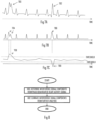
- FIG. 5A illustrates the heart activity measurement signal in the form of a continuous ECG signal.
- the heart activity measurement may be sampled and analogue-to-digital (A/D) converted into a digital signal for signal processing.
- Figure 5A illustrates the QRS complex waveforms used for determining a heart rate, for example.
- Figure 5B illustrates a norm signal, e.g. the output of block 306.
- the norm signal shows clear and distinct peaks at the same timings with the QRS complex waveforms.
- the peaks may be used for computing R-R intervals and/or the heart rate, for example.
- a detection threshold may be used to detect the peaks.
- FIG. 5C shows the phase component of the heart activity signal, e.g. the output of block 304.
- the phase component is a periodic signal.
- the dominating frequency component is directly proportional to a respiratory rate of the user.
- the respiratory rate is also known as a breathing frequency.
- the respiratory rate may be determined from the phase component of the heart activity signal by determining a dominating frequency component in the phase component.
- There are several state-of-the-art solutions for computing the dominating frequency component e.g. by detecting peaks in the phase component and an inverse of an average time interval between the peaks or by computing a fast Fourier transform (FFT) of the phase component and detecting a frequency component containing the highest amount of energy.
- FFT fast Fourier transform
- the periodicity of the phase component of the heart activity measurement signal is determined by determining the dominating frequency component.
- the respiratory rate is determined from the periodicity, wherein the respiratory rate may equal the periodicity.
- the respiratory rate may be stored in a memory unit of the exercise monitoring apparatus, it may be transmitted to another apparatus, and/or it may be output to the user 11 during the exercise (block 604).
- the exercise monitoring apparatus is the sensor device 10 with no user interface
- the sensor device 10 may transmit the respiratory rate to the user interface device 12, 14, and the user interface device 12, 14 may display or otherwise output the respiratory rate to the user 11 during the exercise.
- the exercise monitoring apparatus is the user interface device 12, 14, the exercise monitoring apparatus may output the determined respiratory rate to the user via a user interface of the user interface device 12, 14 during the exercise.
- the respiratory rate may be illustrated to the user 11 via a display screen.
- FIG. 7A illustrates the heart activity measurement signal of Figure 5A , wherein strong interference signal components 700, 702 have been summed into the ECG signal in the electrode(s), for example.
- strong interference may comprise motion artefacts resulting from the motion during the exercise (e.g. running), static electric components generated by the user 11 adjusting his/her shirt, etc.
- the interference signal components 700, 702 also show in the norm signal ( Figure 7B ) as additional peaks 704, 706 that degrade the analysis of the heart activity. It may provide false readings for the heart rate, for example.
- Figure 7C illustrates the phase behaviour of the heart activity measurement signal comprising the interference signal components 700, 702.
- the interference signal components 700, 702 create distinct peaks 708, 709 (a phase shift) to the phase component.
- the phase of the ECG signal remains substantially constant over time (it has the periodic feature illustrated in Figure 5C ), but the phase shifts caused by the interference signal components are typically strong and random in nature.
- the phase variation caused by the interference signal components may be stronger or much stronger than the phase variation caused by the respiratory rate.
- interference peaks 708, 709 in the phase component may be detected and signal components having the timing of the detected peaks of the phase component may be eliminated from the heart activity measurement signal ( Figure 7A ) and/or from the norm signal ( Figure 7B ) such that they will not affect further analysis of the signal(s).
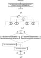
- Block 800 the interference signal components 700, 702 in the heart activity measurement signal ( Figure 7A ) are detected from the phase behaviour of the heart activity measurement signal ( Figure 7C ).
- Block 800 may comprise determining an average level of the phase of the heart activity measurement signal, determining a timing of phase samples of the heart activity measurement signal that deviate from the average level, and eliminating signal components of the heart activity measurement signal and/or the norm signal having said determined timing from further analysis (block 802).
- a signal detection circuitry detecting the QRS complex waveforms from the norm signal may be configured to disregard signal components having the timing of the phase offsets 708, 709 caused by the interference signal components 700, 702. If the detection of the QRS complex waveforms is based on peak detection, the signal detection circuitry may eliminate or disregards any peaks having the timing of the determined interference signal components, e.g. it may eliminate the peaks 704, 706.
- the average level of the phase component may first be determined. As described above, the phase of the ECG signal remains substantially constant, and the average level may be used to approximate the phase of the ECG signal.
- the average level may be computed by computing a mean or a median of the phase component within a determined sampling window. Therefore, the concept of average level represents an effective value of a plurality of successive phase values.
- a tolerance zone may be provided around the average level. The tolerance zone may be defined by a range or by an upper and a lower threshold.
- phase component falling outside the tolerance zone may be determined to be caused by an interference signal component, and the timing of such phase component samples may be stored for the elimination of the corresponding interference signal components in block 802.
- the tolerance zone may be provided around the average level, because interference signal components typically cause a phase shift that may be a positive or negative offset (see phase shifts 708, 709 in Figure 7C ).
- the phase component is used to improve accuracy of estimation of a performance metric.
- the phase component may be used to derive a correction factor that may be used to correct estimation inaccuracies in the performance metric.
- the performance metric is computed from a heart rate variability derived from the heart activity measurement signal.
- the performance metric characterizes user's physiological state before, during, or after training.
- the performance metric characterizes an exertion level of the user.
- the performance metric characterizes the status of the user's sympathetic and/or parasympathetic nervous system before, during or after training.
- the performance metric characterizes the fitness level of the user.
- the performance metric characterizes user's estimated time to recover from the training.
- the performance metric characterizes the stress level of the user.
- a signal shown in Figure 9A illustrates a deviation of R-R intervals of the heart activity measurement signal over time. As can be seen, an average level of the deviation rises at time instant T1 to a next level and stays there. This kind of behaviour may result from a change in the measurement configuration (e.g. a positioning of the electrodes) or in environmental conditions affecting the measurement of the ECG signal.
- Figure 9B illustrates the phase component of the heart activity measurement signal and it has been discovered that the deviation in the phase component increases in proportion to the increase in the deviation of the R-R intervals. Additionally, Figure 9B shows a shift in the average level of the phase component, and the shift may be caused from the change in the measurement configuration, for example.
- this embodiment utilizes the increase in the deviation (or variance or variability) of the phase component.
- a deviation of the phase component of the heart activity measurement signal is computed.
- the phase deviation may be a standard deviation of the phase within a determined observation window.
- a correction factor is computed from the phase deviation.
- the correction factor is used in computation of the performance metric based on the heart rate variability. Correlation between the deviation of the phase component and the deviation of the R-R intervals is found to be linear or at least approximately linear.
- the correction factor scales and/or offsets the computed deviation of the R-R intervals, e.g. the computed deviation of the R-R intervals may be divided by the computed deviation of the phase component.
- Factor "a” may be an inverse of the computed deviation of the phase component.
- an observation interval used for estimating the performance metric is adjusted on the basis of the deviation of the phase component.
- High deviation of the phase may increase errors in the detection of the QRS complexes (see description of Figure 4 ), and the observation interval may be adjusted such that a longer observation (or averaging) interval may be used for higher deviation of the phase component, and a shorter observation interval may be used for a lower deviation of the phase component.
- a longer observation interval for averaging an effect of erroneous or missing detections of the QRS complexes on the performance metric reduces.
- the phase of the QRS complex may affect the performance of any analysis of the heart rate measurement signal that utilizes the detection of the QRS complex waveform. Therefore, it may be advantageous to try to detect the phase of the QRS complex waveform and try to arrange it to be optimal for the detection of the QRS complex waveform.
- Figure 11 illustrates an embodiment of block 202, wherein a phase of the QRS complex waveform is detected from the phase component of the heart activity measurement signal in block 1100. In an embodiment, the phase of the QRS complex waveform is computed from the average level of the phase component.
- the computation of the average level of the phase component may be carried out when computing the average level for the interference component elimination, as described above, or it may be carried out after the interference signal components have been identified and eliminated from the phase component as well. In the latter embodiment, accuracy of the estimation of the phase of the QRS complex waveform may be improved.
- Figures 12 to 14 illustrate embodiments for adjusting the phase of the QRS complex waveform.
- Figure 12 illustrates a measurement configuration used for measuring the ECG signals from the user's body, e.g. from the skin surface.
- Figure 12 illustrates a strap comprising a plurality of electrodes 120, 122, 124, 126.
- the number of electrodes may be at least three but, in general, the number of electrodes may be selected such that at least two different electrode subsets can be arranged to measure the ECG signal.
- electrodes 120, 124 are used to provide a first measurement configuration
- electrodes 122, 126 are used to realize a second measurement configuration. Due to the different positioning of the electrodes, each configuration is tuned to measure an ECG signal vector having a certain direction different from that to the vector direction(s) to which the other configuration(s) is/are tuned.
- Figure 13 illustrates a process for determining an optimal measurement configuration by detecting the phase of the QRS complex waveforms acquired with different measurement configurations and by selecting the measurement configuration providing the most optimal phase of the QRS complex waveform.
- the phase of the QRS complex waveform is computed from a heart activity measurement signal provided by the first measurement configuration in block 1300.
- the phase of the QRS complex waveform is computed from a heart activity measurement signal provided by the second measurement configuration.
- the phase of the QRS complex waveform is computed from one or more heart activity measurement signals provided by one or more other measurement configurations may be computed.
- the sensor device comprising the electrodes 120 to 126 may comprise a switching mechanism to select the electrodes to be used and, thus, switch between the different measurement configurations. In this manner, the different measurement configurations may employ partially the same components in the measurement. Only the set of electrodes may change.
- a measurement configuration providing the most optimal phase of the QRS complex is selected for use, and the heart rate detection and other analysis of the heart activity measurement signal (block 1306) is carried out by using the selected measurement configuration.
- the measurement configuration selection procedure of Figure 13 may be repeated at determined intervals and/or upon detecting an event in the phase of the QRS complex waveform. For example, if the phase of the QRS complex waveform is detected to have shifted, the process of Figure 13 may be repeated. The process of Figure 13 may thus be used to correct the phase shift illustrated in connection with the embodiment of Figures 9A and 9B .
- the user 11 could improve the performance of the heart activity measurements by adjusting the electrode(s).
- the electrodes may need moisture in order to ensure a sufficient electric coupling between the electrodes and the user's 11 skin and, at the beginning of the exercise, the user might improve the electric coupling by moistening the electrodes.
- adjusting the positioning of the electrodes with respect to the user's 11 body might improve the quality of the QRS complex waveform and performance of the detection of the QRS complex.
- the exercise monitoring apparatus outputs, on the basis of analysing the phase component of the heart activity measurement signal, an instruction for the user to adjust at least one electrode measuring the heart activity data.
- Figures 14 to 16 illustrate embodiments for determining what type of adjustment of the electrodes is needed, and the instruction is selected accordingly.
- Figure 14 illustrates two exemplary phase components of heart activity measurement signals.
- the average level of the phase component represents the phase of the QRS complex waveform in the detection circuitry. Keeping the average level of the phase component within a determined range around at least one of the optimal phases of the QRS complex waveform causes efficient performance in the QRS complex detection. The determined range is called "optimal range" in Figure 14 .
- phase component 1400 stays within the optimal range, so no adjustment is needed. However, the phase component 1402 is not within the optimal range, and the exercise monitoring apparatus detecting that the phase component 1402 is not within the optimal range may output the instruction for the user to change the positioning of the electrodes in order to change the direction of the ECG signal vector and change the phase of the QRS complex waveform.
- Figure 15 illustrates a flow diagram of this process according to an embodiment of the invention. Figure 15 illustrates an embodiment of blocks 202 and 204.
- the exercise monitoring apparatus computes the phase of the QRS complex waveform from the phase behaviour of the heart activity measurement signal in block 1100, as described in connection with Figure 11 .
- the phase of the QRS complex waveform may be computed by determining the average level of the phase component within an observation interval. Then, the phase of the QRS complex wave form may be compared with the optimal range determined by at least one phase threshold. In block 1500 it is determined whether or not the phase of the QRS complex waveform falls within the optimal range. If the phase of the QRS complex waveform is within the optimal range, the monitoring of the phase behaviour is continued and the process may return to block 1100.
- the process proceeds to block 1502 in which the instruction to adjust the positioning of the electrodes is output to the user via the user interface.
- the output instruction may specify that the user is instructed to move the electrodes laterally with respect to the user's body, e.g. to the left or to the right.
- the monitoring of the phase of the QRS complex waveform may be continued in block 1100.
- Motion artefacts caused by the user's 11 motion during the exercise may interfere with the measurements.
- a typical interference model is caused by the motion in connection with running, wherein the signal detection circuitry attempting to detect the QRS complexes ends up detecting motion artefacts caused by stride impacts, and the heart rate measurement is distorted to show stride rate.
- the impact in connection with each stride may cause motion of the electrodes with respect to the user's body or motion of clothes the user is wearing, and the result may be a high-level electric interference component induced to the electrodes.
- Figure 16 illustrates an embodiment of a process for detecting the motion artefacts and instructing the user to adjust the electrodes to reduce the motion artefacts.
- the exercise monitoring apparatus computes the deviation in the phase component of the heart activity measurement signal in block 1600.
- FIR represents a low-pass filter
- "*" represents a convolution operation
- abs represents absolute value
- PP represent a difference between consecutive phase samples (P(n)-P(n-1)).
- the low-pass filter serves as an averaging function.
- the motion artefacts are typically strong signal components and have random phase, they dominate over the ECG signal and increase the phase deviation of the phase component. Let us remind that the average level of the phase component stays relatively constant.
- a threshold may be selected sufficiently high such that the deviation caused by the periodicity of the phase component described in connection with Figure 5C does not cause the threshold being exceeded. Equally, any other metric proportional to the deviation may be used, e.g. the variance. If the deviation is below the threshold (or within an allowed range), the monitoring of the phase deviation is continued in block 1600.
- the process proceeds to block 1604 in which an instruction is output to instruct the user to moisten the electrode(s). Moistening improves the electric contact and reduces the motion artefacts.
- This instruction may also be output via the user interface of the exercise monitoring apparatus or through a user interface of another apparatus, e.g. through the user interface device 12, 14 when the exercise monitoring apparatus is the sensor device 10.
- Figure 17 illustrates a block diagram of the exercise monitoring apparatus according to an embodiment of the invention.
- the exercise monitoring apparatus may be sensor device 10, the user interface device 12, 14, or any other apparatus configured to monitor the heart activity measurement signals measured from the user's body during the physical exercise.
- the apparatus comprises a least one processor 60 and at least one memory 70 storing a computer program code 76.
- the computer program code 76 configures the processor to carry out embodiments of the invention, e.g. any one of the embodiments described above.
- the memory 70 may further store a training database 74 in which any parameters and performance metrics measured and/or computed during the exercise may be stored.
- the memory 70 may further store any thresholds 72 and/or any other parameters or criteria used in the embodiments described above.
- the apparatus may further comprise a communication circuitry 52 providing the apparatus with communication capability.
- the communication circuitry may support any wired or wireless communication technique, e.g. Bluetooth, Bluetooth Low energy, IEEE 802.15, IEEE 802.11, W.I.N.D, ANT by Dynastream, or any other radio or induction-based communication technique.
- the apparatus may further comprise at least one sensor 50 configured to measure the heart activity of the user 11.
- the sensor(s) may comprise the above-described electrodes and appropriate circuitry to process the heart activity measurement signals.
- the apparatus may further comprise the user interface 54 for user interaction.
- the user interface 54 may comprise an output device and an input device.
- the output device may comprise a display unit (e.g. a liquid crystal display) and the input device may comprise one or more buttons or keys or a touch-sensitive display.
- the processor 60 may comprise one or more sub-circuitries 62 to 69 configured to carry out the embodiments of the invention.
- the sub-circuitries 62 to 69 may be physical circuitries in the processor 60, or they may be realized by separate computer program modules, and the at least partially the same physical circuitries of the processor may carry out the operations of different modules 62 to 69.
- the processor 60 may receive the heart activity measurement signal from the at least one sensor 50 or through the communication circuitry 52.
- the processor may comprise a phase extraction circuitry 62 configured to extract the phase component from the heart activity measurement signal and output the extracted phase component for further analysis.
- the processor 60 may further comprise a QRS detection circuitry 64 configured to detect the QRS complex waveform from the heart activity measurement signal. The operation of the QRS detection circuitry 64 may be based on detecting the R wave, for example.
- the QRS detection circuitry 64 or the processor 60 may then compute various performance metrics from the detected QRS waveforms, e.g. the heart rate, heart rate variability, energy consumption, and/or exertion level.
- the processor 60 may comprise a QRS phase detection circuitry 66 configured to monitor the phase of the QRS complex waveform from the phase component received from the phase extraction circuitry 62, as described above in connection with Figures 11 to 15 .
- the QRS phase detection circuitry 66 may be configured to carry out at least some of the actions on the basis of the detected phase of the QRS complex waveform, as described above.
- the QRS phase detection circuitry may select an optimal measurement configuration (an optimal set of electrodes to provide the heart activity measurement signal) or control the user interface 54 to output an instruction for the user to adjust the positioning of the electrodes, e.g. to adjust the strap comprising the electrodes.
- the processor 60 may comprise an interference detection circuitry 67 configured to determine the presence of the interference signal components in the heart activity measurement signal and control the elimination of the interference signal components from the analysis of the heart activity measurement signal.
- the interference detection circuitry may carry out the process described above in connection with Figures 7A to 8 , and the interference detection circuitry may output the detected timings of the interference signal components to the QRS detection circuitry 64 such that the QRS detection circuitry 64 may eliminate any signal components having the timing received from the interference detection circuitry 67.
- the interference detection circuitry may receive the heart activity measurement signal before it is input to the QRS detection circuitry 64, remove the interference signal components from the heart activity measurement signal, and output the interference-suppressed heart activity measurement signal to the QRS detection circuitry 64.
- the processor 60 may further comprise a respiratory rate detection circuitry 68 configured to determine the user's respiratory rate from the periodicity of the phase component, as described above in connection with Figures 5 and 6 .
- the processor may further comprise a phase deviation detection circuitry 69 configured to monitor the phase deviation of the phase component.
- the phase deviation detection circuitry may carry out any one of the embodiments described above in connection with Figures 9A, 9B, 10 , and 16 , and carry out a corresponding action.
- the phase deviation detection circuitry 69 may compute the correction factor for use in computation of the performance metric or the heart rate variability in the QRS detection circuitry 64, or the phase deviation detection circuitry 69 may output an instruction for the user to moisten the electrodes.
- circuitry refers to all of the following: (a) hardware-only circuit implementations such as implementations in only analog and/or digital circuitry; (b) combinations of circuits and software and/or firmware, such as (as applicable): (i) a combination of processor(s) or processor cores; or (ii) portions of processor(s)/software including digital signal processor(s), software, and at least one memory that work together to cause an apparatus to perform specific functions; and (c) circuits, such as a microprocessor(s) or a portion of a microprocessor(s), that require software or firmware for operation, even if the software or firmware is not physically present.
- circuitry would also cover an implementation of merely a processor (or multiple processors) or portion of a processor, e.g. one core of a multi-core processor, and its (or their) accompanying software and/or firmware.
- circuitry would also cover, for example and if applicable to the particular element, a baseband integrated circuit, an application-specific integrated circuit (ASIC), and/or a field-programmable grid array (FPGA) circuit for the apparatus according to an embodiment of the invention.
- ASIC application-specific integrated circuit
- FPGA field-programmable grid array
- the processes or methods described in Figures 4 to 8 may also be carried out in the form of a computer process defined by a computer program.
- the computer program may be in source code form, object code form, or in some intermediate form, and it may be stored in some sort of carrier, which may be any entity or device capable of carrying the program.
- Such carriers include transitory and/or non-transitory computer media, e.g. a record medium, computer memory, read-only memory, electrical carrier signal, telecommunications signal, and software distribution package.
- the computer program may be executed in a single electronic digital processing unit or it may be distributed amongst a number of processing units.
- the present invention is applicable to exercise monitoring systems described above but also to other suitable exercise monitoring systems.
- the technology may evolve over time and the development may require extra changes to the described embodiments. Therefore, all words and expressions should be interpreted broadly and they are intended to illustrate, not to restrict, the embodiments. It will be obvious to a person skilled in the art that, as technology advances, the inventive concept can be implemented in various ways.
- the invention and its embodiments are not limited to the examples described above but may vary within the scope of the claims.
Landscapes
- Health & Medical Sciences (AREA)
- Life Sciences & Earth Sciences (AREA)
- Engineering & Computer Science (AREA)
- Public Health (AREA)
- Molecular Biology (AREA)
- Cardiology (AREA)
- Veterinary Medicine (AREA)
- Physics & Mathematics (AREA)
- General Health & Medical Sciences (AREA)
- Biophysics (AREA)
- Pathology (AREA)
- Biomedical Technology (AREA)
- Heart & Thoracic Surgery (AREA)
- Medical Informatics (AREA)
- Animal Behavior & Ethology (AREA)
- Surgery (AREA)
- Physiology (AREA)
- Signal Processing (AREA)
- Computer Vision & Pattern Recognition (AREA)
- Artificial Intelligence (AREA)
- Pulmonology (AREA)
- Psychiatry (AREA)
- Measurement And Recording Of Electrical Phenomena And Electrical Characteristics Of The Living Body (AREA)
- Measuring Pulse, Heart Rate, Blood Pressure Or Blood Flow (AREA)
Claims (13)
- Procédé de traitement d'un signal de mesure d'activité cardiaque dans un appareil de surveillance d'exercice, le procédé comprenant :l'acquisition (200) d'un premier signal de mesure d'activité cardiaque d'un utilisateur pendant un exercice physique réalisé par l'utilisateur, dans lequel le signal de mesure d'activité cardiaque caractérise une activité électrique d'un cœur et est mesuré par une première configuration de mesure utilisant au moins une paire d'électrodes en contact avec la peau de l'utilisateur ;l'acquisition d'au moins un deuxième signal de mesure d'activité cardiaque de l'utilisateur pendant l'exercice physique, dans lequel le deuxième signal de mesure d'activité cardiaque est mesuré par une deuxième configuration de mesure utilisant au moins une paire d'électrodes non utilisées pour mesurer ledit premier signal de mesure d'activité cardiaque ;la surveillance d'une phase d'une forme d'onde de complexe QRS des premier et deuxième signaux de mesure d'activité cardiaque ;la détermination préalable d'au moins une phase d'une forme d'onde de complexe QRS des signaux de mesure d'activité cardiaque qui se traduit par une valeur absolue maximale d'une amplitude d'onde R dans les formes d'onde de complexe QRS des signaux de mesure d'activité cardiaque ;le calcul des phases des premier et deuxième signaux de mesure d'activité cardiaque et la sélection, pour analyse supplémentaire, du signal de mesure d'activité cardiaque dont la phase de la forme d'onde de complexe QRS est la plus proche de l'au moins une phase déterminée de la forme d'onde de complexe QRS qui se traduit par la valeur absolue maximale de l'amplitude d'onde R ; etla détermination d'une action à réaliser sur la base de la phase de la forme d'onde de complexe QRS du signal de mesure d'activité cardiaque sélectionné et la réalisation de ladite action.
- Procédé selon la revendication 1, comprenant en outre :
la détermination d'un paramètre physiologique de l'utilisateur à partir de la phase de la forme d'onde de complexe QRS du signal de mesure d'activité cardiaque de la configuration de mesure sélectionnée. - Procédé selon la revendication 2, où ladite détermination du paramètre physiologique comprend :la détermination d'une périodicité de la phase de la forme d'onde de complexe QRS du signal de mesure d'activité cardiaque de la configuration de mesure sélectionnée ; etla détermination d'une fréquence respiratoire de l'utilisateur à partir de la périodicité.
- Procédé selon l'une quelconque des revendications précédentes, où ladite action comprend :la détermination de composantes de signal d'interférence dans le signal de mesure d'activité cardiaque acquis sur la base de la phase du complexe QRS du signal de mesure d'activité cardiaque de la configuration de mesure sélectionnée ; etl'élimination des composantes de signal d'interférence déterminées de l'analyse supplémentaire du signal de mesure d'activité cardiaque.
- Procédé selon la revendication 4, comprenant en outre :la détermination d'un niveau moyen de la phase du complexe QRS du signal de mesure d'activité cardiaque de la configuration de mesure sélectionnée ;la détermination d'une synchronisation d'échantillons de phase du signal de mesure d'activité cardiaque qui s'écartent du niveau moyen de plus d'un seuil prédéfini ; etl'élimination de composantes de signal ayant ladite synchronisation déterminée de l'analyse supplémentaire du signal d'activité cardiaque.
- Procédé selon l'une quelconque des revendications précédentes, où ladite action comprend :le calcul d'un écart de la phase du complexe QRS du signal de mesure d'activité cardiaque de la configuration de mesure sélectionnée ;le calcul d'au moins un facteur de correction par rapport à l'écart de la phase du complexe QRS du signal de mesure d'activité cardiaque ; etle calcul d'une métrique de performance à partir du signal de mesure d'activité cardiaque en utilisant l'au moins un facteur de correction.
- Procédé selon la revendication 6, où ledit calcul de la métrique de performance comprend :le calcul de la variabilité des intervalles R-R à partir du signal de mesure d'activité cardiaque ; etle calcul de la métrique de performance à partir de la variabilité des intervalles R-R en utilisant l'au moins un facteur de correction.
- Procédé selon l'une quelconque des revendications précédentes, comprenant en outre :
la sortie d'une instruction pour que l'utilisateur règle au moins une électrode mesurant le signal de mesure d'activité cardiaque. - Procédé selon la revendication 8, où l'action comprend :le calcul d'un écart de la phase de la forme d'onde de complexe QRS du signal de mesure d'activité cardiaque ;la détection du dépassement de l'écart d'un seuil prédéterminé ;en réponse à ladite détection, la sortie de l'instruction pour que l'utilisateur règle l'au moins une électrode.
- Procédé selon la revendication 8 ou 9, comprenant en outre :la détermination préalable d'au moins une phase de la forme d'onde de complexe QRS qui se traduit par une valeur absolue maximale d'une amplitude d'onde R du signal de mesure d'activité cardiaque ;la détermination précisant si la phase du signal de mesure d'activité cardiaque se situe ou non dans une plage déterminée par rapport à une phase quelconque de la forme d'onde de complexe QRS qui se traduit par la valeur absolue maximale de l'onde R ; età la détermination du fait que la phase de la forme d'onde de complexe QRS est en dehors de la plage déterminée, la sortie de l'instruction pour que l'utilisateur règle l'au moins une électrode.
- Procédé selon l'une quelconque des revendications précédentes, comprenant en outre :le calcul d'un signal auxiliaire se rapprochant d'une transformée en ondelettes du signal de mesure d'activité cardiaque ; etle calcul de la phase du signal de mesure d'activité cardiaque en calculant un argument du signal auxiliaire.
- Appareil (10, 12, 14), comprenant au moins un processeur (60) ;
et au moins une mémoire (70) comportant un code de programme informatique (76), dans lequel l'au moins une mémoire et le code de programme informatique sont configurés, avec l'au moins un processeur, pour amener l'appareil à effectuer le procédé selon l'une quelconque des revendications précédentes 1 à 11. - Produit de programme informatique incorporé sur un support de distribution lisible par un ordinateur et comprenant des instructions de programme (76) qui, lorsqu'elles sont chargées dans un appareil (10, 12, 14) selon la revendication 12, exécutent le procédé selon l'une quelconque des revendications précédentes 1 à 11.
Priority Applications (1)
| Application Number | Priority Date | Filing Date | Title |
|---|---|---|---|
| EP22217142.3A EP4179966B1 (fr) | 2013-02-14 | 2013-02-14 | Améliorations apportées à la surveillance de l'activité cardiaque pendant un exercice physique |
Applications Claiming Priority (1)
| Application Number | Priority Date | Filing Date | Title |
|---|---|---|---|
| PCT/FI2013/050175 WO2014125159A1 (fr) | 2013-02-14 | 2013-02-14 | Améliorations de la surveillance de l'activité cardiaque pendant un exercice physique |
Related Child Applications (2)
| Application Number | Title | Priority Date | Filing Date |
|---|---|---|---|
| EP22217142.3A Division-Into EP4179966B1 (fr) | 2013-02-14 | 2013-02-14 | Améliorations apportées à la surveillance de l'activité cardiaque pendant un exercice physique |
| EP22217142.3A Division EP4179966B1 (fr) | 2013-02-14 | 2013-02-14 | Améliorations apportées à la surveillance de l'activité cardiaque pendant un exercice physique |
Publications (3)
| Publication Number | Publication Date |
|---|---|
| EP2956051A1 EP2956051A1 (fr) | 2015-12-23 |
| EP2956051B1 true EP2956051B1 (fr) | 2023-06-07 |
| EP2956051C0 EP2956051C0 (fr) | 2023-06-07 |
Family
ID=47891765
Family Applications (2)
| Application Number | Title | Priority Date | Filing Date |
|---|---|---|---|
| EP22217142.3A Active EP4179966B1 (fr) | 2013-02-14 | 2013-02-14 | Améliorations apportées à la surveillance de l'activité cardiaque pendant un exercice physique |
| EP13709954.5A Active EP2956051B1 (fr) | 2013-02-14 | 2013-02-14 | Améliorations de la surveillance de l'activité cardiaque pendant un exercice physique |
Family Applications Before (1)
| Application Number | Title | Priority Date | Filing Date |
|---|---|---|---|
| EP22217142.3A Active EP4179966B1 (fr) | 2013-02-14 | 2013-02-14 | Améliorations apportées à la surveillance de l'activité cardiaque pendant un exercice physique |
Country Status (3)
| Country | Link |
|---|---|
| US (2) | US11534075B2 (fr) |
| EP (2) | EP4179966B1 (fr) |
| WO (1) | WO2014125159A1 (fr) |
Families Citing this family (5)
| Publication number | Priority date | Publication date | Assignee | Title |
|---|---|---|---|---|
| CN107105804B (zh) * | 2014-11-19 | 2020-10-30 | 耐克创新有限合伙公司 | 具有可移除模块的运动带 |
| DK3282939T3 (da) * | 2015-04-14 | 2021-05-31 | Lifewatch Tech Ltd | Justering af en aftagelig monitoreringsindretning |
| US10456088B2 (en) | 2015-07-16 | 2019-10-29 | Samsung Electronics Company, Ltd. | Performance of biological measurements in the presence of noise |
| EP3419519B1 (fr) * | 2016-06-15 | 2020-07-15 | Samsung Electronics Co., Ltd. | Amélioration de la performance des mesures biologiques en présence de bruit |
| CN121533569A (zh) | 2017-04-12 | 2026-02-17 | 耐克创新有限合伙公司 | 具有可拆卸模块的可穿戴物品 |
Family Cites Families (9)
| Publication number | Priority date | Publication date | Assignee | Title |
|---|---|---|---|---|
| US5025795A (en) * | 1989-06-28 | 1991-06-25 | Kunig Horst E | Non-invasive cardiac performance monitoring device and method |
| AU2003263571A1 (en) * | 2002-09-19 | 2004-04-08 | Ramot At Tel Aviv University Ltd. | Method, apparatus and system for characterizing sleep |
| US7136694B2 (en) | 2004-03-30 | 2006-11-14 | Cardiac Science Corporation | Methods for quantifying the morphology and amplitude of cardiac action potential alternans |
| WO2009147279A1 (fr) * | 2008-06-02 | 2009-12-10 | Polar Electro Oy | Procédé et appareil utiles dans le cadre de l’exercice physique |
| US8805485B2 (en) * | 2008-11-21 | 2014-08-12 | Massachusetts Institute Of Technology | Extraction of fetal cardiac signals |
| US8798732B2 (en) | 2010-08-05 | 2014-08-05 | Lev-El Diagnostics of Heart Diseases Ltd. | Apparatus, system and method of determining a heart rate variability value |
| WO2012137213A1 (fr) * | 2011-04-05 | 2012-10-11 | Neurokeeper Technologies Ltd. | Système et procédé de détection d'une détérioration neurologique |
| EP2589332A1 (fr) * | 2011-11-03 | 2013-05-08 | Imec | Système et procédé pour l'analyse de signaux d'électrocardiogramme |
| WO2014021883A1 (fr) * | 2012-08-01 | 2014-02-06 | Draeger Medical Systems, Inc. | Système et procédé de mesure d'impédance de contact d'une électrode |
-
2013
- 2013-02-14 WO PCT/FI2013/050175 patent/WO2014125159A1/fr not_active Ceased
- 2013-02-14 EP EP22217142.3A patent/EP4179966B1/fr active Active
- 2013-02-14 US US14/767,225 patent/US11534075B2/en active Active
- 2013-02-14 EP EP13709954.5A patent/EP2956051B1/fr active Active
-
2022
- 2022-11-22 US US17/992,625 patent/US12433500B2/en active Active
Also Published As
| Publication number | Publication date |
|---|---|
| WO2014125159A1 (fr) | 2014-08-21 |
| EP4179966C0 (fr) | 2024-11-06 |
| EP2956051A1 (fr) | 2015-12-23 |
| US11534075B2 (en) | 2022-12-27 |
| EP4179966A1 (fr) | 2023-05-17 |
| US12433500B2 (en) | 2025-10-07 |
| EP4179966B1 (fr) | 2024-11-06 |
| EP2956051C0 (fr) | 2023-06-07 |
| US20160000336A1 (en) | 2016-01-07 |
| US20230091163A1 (en) | 2023-03-23 |
Similar Documents
| Publication | Publication Date | Title |
|---|---|---|
| US12433500B2 (en) | Heart activity monitoring during physical exercise | |
| EP4085834A1 (fr) | Procédé de traitement de données d'exercice et système de surveillance d'exercice | |
| EP2730216B1 (fr) | Émetteur de biosignaux, récepteur de biosignaux et procédé d'émission de biosignaux | |
| EP3478166B1 (fr) | Estimation à la demande de la fréquence cardiaque sur la base de mesures optiques | |
| US9936886B2 (en) | Method for the estimation of the heart-rate and corresponding system | |
| EP3048972B1 (fr) | Appareil de traitement, procédé et système de traitement pour traiter un signal physiologique | |
| US20130070792A1 (en) | Method and apparatus for denoising of physiological signals | |
| WO2016057781A1 (fr) | Procédé et appareil pour l'acquisition de signes vitaux rapide sans contact sur la base d'un signal radar | |
| EP2589332A1 (fr) | Système et procédé pour l'analyse de signaux d'électrocardiogramme | |
| US11457865B2 (en) | Wearable sports monitoring equipment for measuring heart rate or muscular activity and relating method | |
| WO2015107268A1 (fr) | Procédé et dispositif de détection d'une fréquence respiratoire | |
| US20170127960A1 (en) | Method and apparatus for estimating heart rate based on movement information | |
| EP2967392B1 (fr) | Procédé amélioré de calcul d'ecg destiné à être utilisé dans la production de mesures d'ecg à 12 dérivations à partir de dispositifs qui ont moins de 10 électrodes | |
| KR20140089897A (ko) | 저전력 생체신호 모니터링 방법 및 장치 | |
| CN108652611A (zh) | 一种心率的计算方法、装置、设备及计算机可读存储介质 | |
| JP6519344B2 (ja) | 心拍間隔特定プログラム、心拍間隔特定装置、及び心拍間隔特定方法 | |
| US20190269350A1 (en) | Respiratory state estimation apparatus, respiratory state estimation method, and program recording medium | |
| US20190231227A1 (en) | Breathing activity monitoring device, corresponding system and method | |
| US12178558B2 (en) | Biometric information processing apparatus and biometric information processing method | |
| US20180333075A1 (en) | Respiratory rate measuring method and apparatus, and wearable device | |
| He et al. | TreMo: Continuous Vital Sign Monitoring Based on Subtle Intrinsic Tremors with COTS Mobile Devices | |
| CN119622224A (zh) | 处理生物信号的装置和方法 | |
| HK40078432B (en) | Exercise data processing method and exercise monitoring system | |
| HK40078432A (en) | Exercise data processing method and exercise monitoring system | |
| HK1236786A1 (en) | System and method for heart rate monitoring of an object |
Legal Events
| Date | Code | Title | Description |
|---|---|---|---|
| PUAI | Public reference made under article 153(3) epc to a published international application that has entered the european phase |
Free format text: ORIGINAL CODE: 0009012 |
|
| 17P | Request for examination filed |
Effective date: 20150804 |
|
| AK | Designated contracting states |
Kind code of ref document: A1 Designated state(s): AL AT BE BG CH CY CZ DE DK EE ES FI FR GB GR HR HU IE IS IT LI LT LU LV MC MK MT NL NO PL PT RO RS SE SI SK SM TR |
|
| AX | Request for extension of the european patent |
Extension state: BA ME |
|
| DAX | Request for extension of the european patent (deleted) | ||
| STAA | Information on the status of an ep patent application or granted ep patent |
Free format text: STATUS: EXAMINATION IS IN PROGRESS |
|
| 17Q | First examination report despatched |
Effective date: 20190702 |
|
| RIC1 | Information provided on ipc code assigned before grant |
Ipc: A61B 5/349 20210101ALI20220819BHEP Ipc: A61B 5/08 20060101ALI20220819BHEP Ipc: A61B 5/00 20060101ALI20220819BHEP Ipc: A61B 5/0245 20060101ALI20220819BHEP Ipc: A63B 24/00 20060101ALI20220819BHEP Ipc: A61B 5/024 20060101AFI20220819BHEP |
|
| GRAP | Despatch of communication of intention to grant a patent |
Free format text: ORIGINAL CODE: EPIDOSNIGR1 |
|
| STAA | Information on the status of an ep patent application or granted ep patent |
Free format text: STATUS: GRANT OF PATENT IS INTENDED |
|
| INTG | Intention to grant announced |
Effective date: 20220930 |
|
| GRAS | Grant fee paid |
Free format text: ORIGINAL CODE: EPIDOSNIGR3 |
|
| GRAA | (expected) grant |
Free format text: ORIGINAL CODE: 0009210 |
|
| STAA | Information on the status of an ep patent application or granted ep patent |
Free format text: STATUS: THE PATENT HAS BEEN GRANTED |
|
| AK | Designated contracting states |
Kind code of ref document: B1 Designated state(s): AL AT BE BG CH CY CZ DE DK EE ES FI FR GB GR HR HU IE IS IT LI LT LU LV MC MK MT NL NO PL PT RO RS SE SI SK SM TR |
|
| REG | Reference to a national code |
Ref country code: GB Ref legal event code: FG4D |
|
| REG | Reference to a national code |
Ref country code: CH Ref legal event code: EP Ref country code: AT Ref legal event code: REF Ref document number: 1572334 Country of ref document: AT Kind code of ref document: T Effective date: 20230615 |
|
| REG | Reference to a national code |
Ref country code: DE Ref legal event code: R096 Ref document number: 602013083899 Country of ref document: DE |
|
| U01 | Request for unitary effect filed |
Effective date: 20230614 |
|
| U07 | Unitary effect registered |
Designated state(s): AT BE BG DE DK EE FI FR IT LT LU LV MT NL PT SE SI Effective date: 20230621 |
|
| REG | Reference to a national code |
Ref country code: LT Ref legal event code: MG9D |
|
| PG25 | Lapsed in a contracting state [announced via postgrant information from national office to epo] |
Ref country code: NO Free format text: LAPSE BECAUSE OF FAILURE TO SUBMIT A TRANSLATION OF THE DESCRIPTION OR TO PAY THE FEE WITHIN THE PRESCRIBED TIME-LIMIT Effective date: 20230907 Ref country code: ES Free format text: LAPSE BECAUSE OF FAILURE TO SUBMIT A TRANSLATION OF THE DESCRIPTION OR TO PAY THE FEE WITHIN THE PRESCRIBED TIME-LIMIT Effective date: 20230607 |
|
| PG25 | Lapsed in a contracting state [announced via postgrant information from national office to epo] |
Ref country code: RS Free format text: LAPSE BECAUSE OF FAILURE TO SUBMIT A TRANSLATION OF THE DESCRIPTION OR TO PAY THE FEE WITHIN THE PRESCRIBED TIME-LIMIT Effective date: 20230607 Ref country code: HR Free format text: LAPSE BECAUSE OF FAILURE TO SUBMIT A TRANSLATION OF THE DESCRIPTION OR TO PAY THE FEE WITHIN THE PRESCRIBED TIME-LIMIT Effective date: 20230607 Ref country code: GR Free format text: LAPSE BECAUSE OF FAILURE TO SUBMIT A TRANSLATION OF THE DESCRIPTION OR TO PAY THE FEE WITHIN THE PRESCRIBED TIME-LIMIT Effective date: 20230908 |
|
| PG25 | Lapsed in a contracting state [announced via postgrant information from national office to epo] |
Ref country code: SK Free format text: LAPSE BECAUSE OF FAILURE TO SUBMIT A TRANSLATION OF THE DESCRIPTION OR TO PAY THE FEE WITHIN THE PRESCRIBED TIME-LIMIT Effective date: 20230607 |
|
| PG25 | Lapsed in a contracting state [announced via postgrant information from national office to epo] |
Ref country code: IS Free format text: LAPSE BECAUSE OF FAILURE TO SUBMIT A TRANSLATION OF THE DESCRIPTION OR TO PAY THE FEE WITHIN THE PRESCRIBED TIME-LIMIT Effective date: 20231007 |
|
| PG25 | Lapsed in a contracting state [announced via postgrant information from national office to epo] |
Ref country code: SM Free format text: LAPSE BECAUSE OF FAILURE TO SUBMIT A TRANSLATION OF THE DESCRIPTION OR TO PAY THE FEE WITHIN THE PRESCRIBED TIME-LIMIT Effective date: 20230607 Ref country code: SK Free format text: LAPSE BECAUSE OF FAILURE TO SUBMIT A TRANSLATION OF THE DESCRIPTION OR TO PAY THE FEE WITHIN THE PRESCRIBED TIME-LIMIT Effective date: 20230607 Ref country code: RO Free format text: LAPSE BECAUSE OF FAILURE TO SUBMIT A TRANSLATION OF THE DESCRIPTION OR TO PAY THE FEE WITHIN THE PRESCRIBED TIME-LIMIT Effective date: 20230607 Ref country code: IS Free format text: LAPSE BECAUSE OF FAILURE TO SUBMIT A TRANSLATION OF THE DESCRIPTION OR TO PAY THE FEE WITHIN THE PRESCRIBED TIME-LIMIT Effective date: 20231007 Ref country code: CZ Free format text: LAPSE BECAUSE OF FAILURE TO SUBMIT A TRANSLATION OF THE DESCRIPTION OR TO PAY THE FEE WITHIN THE PRESCRIBED TIME-LIMIT Effective date: 20230607 |
|
| PG25 | Lapsed in a contracting state [announced via postgrant information from national office to epo] |
Ref country code: PL Free format text: LAPSE BECAUSE OF FAILURE TO SUBMIT A TRANSLATION OF THE DESCRIPTION OR TO PAY THE FEE WITHIN THE PRESCRIBED TIME-LIMIT Effective date: 20230607 |
|
| REG | Reference to a national code |
Ref country code: DE Ref legal event code: R097 Ref document number: 602013083899 Country of ref document: DE |
|
| U20 | Renewal fee for the european patent with unitary effect paid |
Year of fee payment: 12 Effective date: 20240215 |
|
| PLBE | No opposition filed within time limit |
Free format text: ORIGINAL CODE: 0009261 |
|
| STAA | Information on the status of an ep patent application or granted ep patent |
Free format text: STATUS: NO OPPOSITION FILED WITHIN TIME LIMIT |
|
| 26N | No opposition filed |
Effective date: 20240308 |
|
| PG25 | Lapsed in a contracting state [announced via postgrant information from national office to epo] |
Ref country code: MC Free format text: LAPSE BECAUSE OF FAILURE TO SUBMIT A TRANSLATION OF THE DESCRIPTION OR TO PAY THE FEE WITHIN THE PRESCRIBED TIME-LIMIT Effective date: 20230607 |
|
| REG | Reference to a national code |
Ref country code: CH Ref legal event code: PL |
|
| PG25 | Lapsed in a contracting state [announced via postgrant information from national office to epo] |
Ref country code: CH Free format text: LAPSE BECAUSE OF NON-PAYMENT OF DUE FEES Effective date: 20240229 |
|
| GBPC | Gb: european patent ceased through non-payment of renewal fee |
Effective date: 20240214 |
|
| PG25 | Lapsed in a contracting state [announced via postgrant information from national office to epo] |
Ref country code: CH Free format text: LAPSE BECAUSE OF NON-PAYMENT OF DUE FEES Effective date: 20240229 |
|
| PG25 | Lapsed in a contracting state [announced via postgrant information from national office to epo] |
Ref country code: GB Free format text: LAPSE BECAUSE OF NON-PAYMENT OF DUE FEES Effective date: 20240214 |
|
| PG25 | Lapsed in a contracting state [announced via postgrant information from national office to epo] |
Ref country code: IE Free format text: LAPSE BECAUSE OF NON-PAYMENT OF DUE FEES Effective date: 20240214 |
|
| PG25 | Lapsed in a contracting state [announced via postgrant information from national office to epo] |
Ref country code: IE Free format text: LAPSE BECAUSE OF NON-PAYMENT OF DUE FEES Effective date: 20240214 Ref country code: GB Free format text: LAPSE BECAUSE OF NON-PAYMENT OF DUE FEES Effective date: 20240214 |
|
| U20 | Renewal fee for the european patent with unitary effect paid |
Year of fee payment: 13 Effective date: 20250218 |
|
| PG25 | Lapsed in a contracting state [announced via postgrant information from national office to epo] |
Ref country code: CY Free format text: LAPSE BECAUSE OF FAILURE TO SUBMIT A TRANSLATION OF THE DESCRIPTION OR TO PAY THE FEE WITHIN THE PRESCRIBED TIME-LIMIT; INVALID AB INITIO Effective date: 20130214 |
|
| PG25 | Lapsed in a contracting state [announced via postgrant information from national office to epo] |
Ref country code: HU Free format text: LAPSE BECAUSE OF FAILURE TO SUBMIT A TRANSLATION OF THE DESCRIPTION OR TO PAY THE FEE WITHIN THE PRESCRIBED TIME-LIMIT; INVALID AB INITIO Effective date: 20130214 |
|
| PG25 | Lapsed in a contracting state [announced via postgrant information from national office to epo] |
Ref country code: TR Free format text: LAPSE BECAUSE OF FAILURE TO SUBMIT A TRANSLATION OF THE DESCRIPTION OR TO PAY THE FEE WITHIN THE PRESCRIBED TIME-LIMIT Effective date: 20230607 |
|
| U20 | Renewal fee for the european patent with unitary effect paid |
Year of fee payment: 14 Effective date: 20260216 |