EP2956094B1 - Fixations de surmoulage pour pied prothétique - Google Patents
Fixations de surmoulage pour pied prothétique Download PDFInfo
- Publication number
- EP2956094B1 EP2956094B1 EP14751312.1A EP14751312A EP2956094B1 EP 2956094 B1 EP2956094 B1 EP 2956094B1 EP 14751312 A EP14751312 A EP 14751312A EP 2956094 B1 EP2956094 B1 EP 2956094B1
- Authority
- EP
- European Patent Office
- Prior art keywords
- foot
- attachment
- prosthetic foot
- toe
- prosthetic
- Prior art date
- Legal status (The legal status is an assumption and is not a legal conclusion. Google has not performed a legal analysis and makes no representation as to the accuracy of the status listed.)
- Active
Links
Images


















Classifications
-
- A—HUMAN NECESSITIES
- A61—MEDICAL OR VETERINARY SCIENCE; HYGIENE
- A61F—FILTERS IMPLANTABLE INTO BLOOD VESSELS; PROSTHESES; DEVICES PROVIDING PATENCY TO, OR PREVENTING COLLAPSING OF, TUBULAR STRUCTURES OF THE BODY, e.g. STENTS; ORTHOPAEDIC, NURSING OR CONTRACEPTIVE DEVICES; FOMENTATION; TREATMENT OR PROTECTION OF EYES OR EARS; BANDAGES, DRESSINGS OR ABSORBENT PADS; FIRST-AID KITS
- A61F2/00—Filters implantable into blood vessels; Prostheses, i.e. artificial substitutes or replacements for parts of the body; Appliances for connecting them with the body; Devices providing patency to, or preventing collapsing of, tubular structures of the body, e.g. stents
- A61F2/50—Prostheses not implantable in the body
- A61F2/60—Artificial legs or feet or parts thereof
- A61F2/66—Feet; Ankle joints
-
- A—HUMAN NECESSITIES
- A61—MEDICAL OR VETERINARY SCIENCE; HYGIENE
- A61F—FILTERS IMPLANTABLE INTO BLOOD VESSELS; PROSTHESES; DEVICES PROVIDING PATENCY TO, OR PREVENTING COLLAPSING OF, TUBULAR STRUCTURES OF THE BODY, e.g. STENTS; ORTHOPAEDIC, NURSING OR CONTRACEPTIVE DEVICES; FOMENTATION; TREATMENT OR PROTECTION OF EYES OR EARS; BANDAGES, DRESSINGS OR ABSORBENT PADS; FIRST-AID KITS
- A61F2/00—Filters implantable into blood vessels; Prostheses, i.e. artificial substitutes or replacements for parts of the body; Appliances for connecting them with the body; Devices providing patency to, or preventing collapsing of, tubular structures of the body, e.g. stents
- A61F2/50—Prostheses not implantable in the body
- A61F2/76—Means for assembling, fitting or testing prostheses, e.g. for measuring or balancing, e.g. alignment means
-
- A—HUMAN NECESSITIES
- A61—MEDICAL OR VETERINARY SCIENCE; HYGIENE
- A61F—FILTERS IMPLANTABLE INTO BLOOD VESSELS; PROSTHESES; DEVICES PROVIDING PATENCY TO, OR PREVENTING COLLAPSING OF, TUBULAR STRUCTURES OF THE BODY, e.g. STENTS; ORTHOPAEDIC, NURSING OR CONTRACEPTIVE DEVICES; FOMENTATION; TREATMENT OR PROTECTION OF EYES OR EARS; BANDAGES, DRESSINGS OR ABSORBENT PADS; FIRST-AID KITS
- A61F2/00—Filters implantable into blood vessels; Prostheses, i.e. artificial substitutes or replacements for parts of the body; Appliances for connecting them with the body; Devices providing patency to, or preventing collapsing of, tubular structures of the body, e.g. stents
- A61F2/50—Prostheses not implantable in the body
- A61F2002/5001—Cosmetic coverings
-
- A—HUMAN NECESSITIES
- A61—MEDICAL OR VETERINARY SCIENCE; HYGIENE
- A61F—FILTERS IMPLANTABLE INTO BLOOD VESSELS; PROSTHESES; DEVICES PROVIDING PATENCY TO, OR PREVENTING COLLAPSING OF, TUBULAR STRUCTURES OF THE BODY, e.g. STENTS; ORTHOPAEDIC, NURSING OR CONTRACEPTIVE DEVICES; FOMENTATION; TREATMENT OR PROTECTION OF EYES OR EARS; BANDAGES, DRESSINGS OR ABSORBENT PADS; FIRST-AID KITS
- A61F2/00—Filters implantable into blood vessels; Prostheses, i.e. artificial substitutes or replacements for parts of the body; Appliances for connecting them with the body; Devices providing patency to, or preventing collapsing of, tubular structures of the body, e.g. stents
- A61F2/50—Prostheses not implantable in the body
- A61F2002/5016—Prostheses not implantable in the body adjustable
-
- A—HUMAN NECESSITIES
- A61—MEDICAL OR VETERINARY SCIENCE; HYGIENE
- A61F—FILTERS IMPLANTABLE INTO BLOOD VESSELS; PROSTHESES; DEVICES PROVIDING PATENCY TO, OR PREVENTING COLLAPSING OF, TUBULAR STRUCTURES OF THE BODY, e.g. STENTS; ORTHOPAEDIC, NURSING OR CONTRACEPTIVE DEVICES; FOMENTATION; TREATMENT OR PROTECTION OF EYES OR EARS; BANDAGES, DRESSINGS OR ABSORBENT PADS; FIRST-AID KITS
- A61F2/00—Filters implantable into blood vessels; Prostheses, i.e. artificial substitutes or replacements for parts of the body; Appliances for connecting them with the body; Devices providing patency to, or preventing collapsing of, tubular structures of the body, e.g. stents
- A61F2/50—Prostheses not implantable in the body
- A61F2002/5016—Prostheses not implantable in the body adjustable
- A61F2002/5024—Prostheses not implantable in the body adjustable for adjusting thickness
-
- A—HUMAN NECESSITIES
- A61—MEDICAL OR VETERINARY SCIENCE; HYGIENE
- A61F—FILTERS IMPLANTABLE INTO BLOOD VESSELS; PROSTHESES; DEVICES PROVIDING PATENCY TO, OR PREVENTING COLLAPSING OF, TUBULAR STRUCTURES OF THE BODY, e.g. STENTS; ORTHOPAEDIC, NURSING OR CONTRACEPTIVE DEVICES; FOMENTATION; TREATMENT OR PROTECTION OF EYES OR EARS; BANDAGES, DRESSINGS OR ABSORBENT PADS; FIRST-AID KITS
- A61F2/00—Filters implantable into blood vessels; Prostheses, i.e. artificial substitutes or replacements for parts of the body; Appliances for connecting them with the body; Devices providing patency to, or preventing collapsing of, tubular structures of the body, e.g. stents
- A61F2/50—Prostheses not implantable in the body
- A61F2002/5016—Prostheses not implantable in the body adjustable
- A61F2002/5027—Prostheses not implantable in the body adjustable for adjusting cross-section
-
- A—HUMAN NECESSITIES
- A61—MEDICAL OR VETERINARY SCIENCE; HYGIENE
- A61F—FILTERS IMPLANTABLE INTO BLOOD VESSELS; PROSTHESES; DEVICES PROVIDING PATENCY TO, OR PREVENTING COLLAPSING OF, TUBULAR STRUCTURES OF THE BODY, e.g. STENTS; ORTHOPAEDIC, NURSING OR CONTRACEPTIVE DEVICES; FOMENTATION; TREATMENT OR PROTECTION OF EYES OR EARS; BANDAGES, DRESSINGS OR ABSORBENT PADS; FIRST-AID KITS
- A61F2/00—Filters implantable into blood vessels; Prostheses, i.e. artificial substitutes or replacements for parts of the body; Appliances for connecting them with the body; Devices providing patency to, or preventing collapsing of, tubular structures of the body, e.g. stents
- A61F2/50—Prostheses not implantable in the body
- A61F2002/5016—Prostheses not implantable in the body adjustable
- A61F2002/503—Prostheses not implantable in the body adjustable for adjusting elasticity, flexibility, spring rate or mechanical tension
-
- A—HUMAN NECESSITIES
- A61—MEDICAL OR VETERINARY SCIENCE; HYGIENE
- A61F—FILTERS IMPLANTABLE INTO BLOOD VESSELS; PROSTHESES; DEVICES PROVIDING PATENCY TO, OR PREVENTING COLLAPSING OF, TUBULAR STRUCTURES OF THE BODY, e.g. STENTS; ORTHOPAEDIC, NURSING OR CONTRACEPTIVE DEVICES; FOMENTATION; TREATMENT OR PROTECTION OF EYES OR EARS; BANDAGES, DRESSINGS OR ABSORBENT PADS; FIRST-AID KITS
- A61F2/00—Filters implantable into blood vessels; Prostheses, i.e. artificial substitutes or replacements for parts of the body; Appliances for connecting them with the body; Devices providing patency to, or preventing collapsing of, tubular structures of the body, e.g. stents
- A61F2/50—Prostheses not implantable in the body
- A61F2002/5081—Additional features
- A61F2002/5083—Additional features modular
-
- A—HUMAN NECESSITIES
- A61—MEDICAL OR VETERINARY SCIENCE; HYGIENE
- A61F—FILTERS IMPLANTABLE INTO BLOOD VESSELS; PROSTHESES; DEVICES PROVIDING PATENCY TO, OR PREVENTING COLLAPSING OF, TUBULAR STRUCTURES OF THE BODY, e.g. STENTS; ORTHOPAEDIC, NURSING OR CONTRACEPTIVE DEVICES; FOMENTATION; TREATMENT OR PROTECTION OF EYES OR EARS; BANDAGES, DRESSINGS OR ABSORBENT PADS; FIRST-AID KITS
- A61F2/00—Filters implantable into blood vessels; Prostheses, i.e. artificial substitutes or replacements for parts of the body; Appliances for connecting them with the body; Devices providing patency to, or preventing collapsing of, tubular structures of the body, e.g. stents
- A61F2/50—Prostheses not implantable in the body
- A61F2/60—Artificial legs or feet or parts thereof
- A61F2/66—Feet; Ankle joints
- A61F2002/6614—Feet
- A61F2002/6621—Toes
-
- A—HUMAN NECESSITIES
- A61—MEDICAL OR VETERINARY SCIENCE; HYGIENE
- A61F—FILTERS IMPLANTABLE INTO BLOOD VESSELS; PROSTHESES; DEVICES PROVIDING PATENCY TO, OR PREVENTING COLLAPSING OF, TUBULAR STRUCTURES OF THE BODY, e.g. STENTS; ORTHOPAEDIC, NURSING OR CONTRACEPTIVE DEVICES; FOMENTATION; TREATMENT OR PROTECTION OF EYES OR EARS; BANDAGES, DRESSINGS OR ABSORBENT PADS; FIRST-AID KITS
- A61F2/00—Filters implantable into blood vessels; Prostheses, i.e. artificial substitutes or replacements for parts of the body; Appliances for connecting them with the body; Devices providing patency to, or preventing collapsing of, tubular structures of the body, e.g. stents
- A61F2/50—Prostheses not implantable in the body
- A61F2/60—Artificial legs or feet or parts thereof
- A61F2/66—Feet; Ankle joints
- A61F2002/6614—Feet
- A61F2002/6657—Feet having a plate-like or strip-like spring element, e.g. an energy-storing cantilever spring keel
Definitions
- Embodiments of the present invention relate to prosthetic feet and overmould attachments and cosmetic covers for prosthetic feet.
- Prosthetic feet of different designs are well known in the art.
- the various conventional designs have sought to solve various limitations associated with prosthetic feet.
- One limitation associated with prosthetic feet known in the art has to do with manufacturing prosthetic feet having foot plates with varying characteristics.
- Some of the possible variations of a foot plate include width, length, thickness, shape, and stiffness. Incorporating one or more of these variations into the design of a prosthesis can result in a prosthesis with characteristics that are desirable or beneficial for a particular user or a particular use.
- incorporating these variations directly into the foot plate during the manufacturing process can be expensive, time consuming and result in waste of the production materials.
- prosthetic feet Another limitation associated with prosthetic feet known in the art has to do with wear and tear on the prosthesis.
- Materials typically used in the art to produce prosthetic feet, such as carbon fiber, can be expensive and difficult to repair or replace.
- normal wear and tear can result in undesirable cosmetic or structural damage to the foot plate or any other element of the prosthesis. Such damage can be very difficult or expensive to repair and can require that the entire foot plate of the prosthesis be replaced.
- US20050038524 discloses a prosthetic foot with a crepe portion 16 attached to the underside of a foot member
- WO2012/009319 A2 discloses a prosthetic foot device with an attachment coupling lateral sides of the footplate and a primary forefoot spring arc.
- the attachment can be formed by wrapping the toe ends with fiber in resin matrix.
- WO 2012/009319 A2 is considered the closed prior art.
- US 2012/0271434 A1 discloses a prosthetic foot with a base spring with receiving means with insertion openings.
- a prosthetic toot comprising at least one foot plate that can be coupled to an attachment.
- the foot plate has a toe end, an ankle end, a toe surface or edge, an ankle surface or edge, medial and lateral side surfaces or edges, a top surface, and a bottom surface.
- the foot plate can be made of carbon fiber or any other material used in the art to manufacture foot plates for prosthetic feet.
- the foot plate can be generally straight, or it can be curved between the toe end and the ankle end such that the toe end is substantially horizontal while the ankle end is substantially vertical.
- the foot plate can be coupled to an attachment at the toe end, wherein the attachment extends at least partially along the length of the side surfaces from the toe end toward the ankle end.
- the attachment extends all the way along the side surfaces wherein it is also coupled to the ankle surface. In embodiments in which the foot plate is curved and the attachment extends along the sides to at least the portion where the foot plate is curved, the portion of the attachment along the side surfaces will also curve to match the side surfaces.
- the foot plate can be coupled to an attachment that can extend at least partially over the top surface and/or at least partially over the bottom surface of the foot plate.
- the prosthetic foot can have a heel plate connected to the bottom surface of the foot plate and extending away from the toe end of the foot plate.
- the foot plate can be removably coupled to the attachment.
- the foot plate can be coupled to the attachment using at least one clip mechanism, a series of clips, glue or epoxy, magnetic force, elastic properties of the attachment (e.g., press-fit connection) and/or any other coupling mechanism known in the art.
- the attachment is not coupled with or in contact with the heel plate.
- the attachment can alter the shape of the foot plate such that the altered shape of the foot plate is more similar to the shape of a natural human foot.
- the altered shape of the foot plate can provide the prosthetic foot and its user with other functional or cosmetic benefits.
- the altered shape of the foot plate can aid in fitting the prosthesis into a foot cover or shoe.
- the foot plate has a lengthwise split beginning at the toe end of the foot plate and traversing at least part of the length of the foot plate that divides the foot plate resulting in a medial portion and a lateral portion.
- the lengthwise split does not span the entire length of the foot plate, and thus the medial and lateral portions join into a singular foot plate at some point between the toe end and the ankle end of the foot plate.
- the attachment will have a corresponding split at the toe end. The split in the foot plate and the attachment allow the medial and lateral portions to flex at least somewhat independently, improving functional properties of the prosthetic foot during rollover.
- a prosthetic foot with a foot plate that can receive a coupleable toe attachment at the toe end of the foot plate.
- the foot plate has a toe end, an ankle end, a toe surface, an ankle surface, medial and lateral side surfaces, a top surface, and a bottom surfaces.
- the foot plate can be made of carbon fiber or any other material used in the art to manufacture foot plates for prosthetic feet.
- the foot plate can be straight, or it can be curved between the toe end and the ankle end such that the toe end is substantially horizontal while the ankle end is substantially vertical.
- the ankle end of the foot plate can attach to an adaptor or a residual limb.
- the foot plate has sides that are substantially straight resulting in a more economical and efficient manufacturing process.
- the foot plate is manufactured to a standard size resulting in a more economical and efficient manufacturing process.
- the foot plate can be coupled at the toe end to a toe attachment that extends at least partially over the top surface and at least partially over the bottom surface of the foot plate.
- the foot plate can be removably coupled to the toe attachment, the toe attachment having a cavity that can receive the toe end of the foot plate.
- the toe attachment alters the shape of the foot plate such that the altered shape of the foot plate is more similar to the shape of a natural human foot.
- the altered shape of the foot plate can aid in fitting the prosthesis into a foot cover or shoe.
- an overmould attachment that is coupleable to a foot plate of a prosthetic foot.
- the overmould attachment is coupled to the toe end or toe surface of the foot plate, and at least partially along the medial and lateral side surfaces of the foot plate.
- the attachment extends along the entire length of the side surfaces and at least partially onto an ankle surface of they foot plate.
- the attachment is removably coupleable to a prosthetic foot.
- the attachment is made out of polymer or a plastic-like material or a compressible materials. In other embodiments, the attachment is made of any material used in the art. The attachment can alter the stiffness or thickness characteristics of the foot plate.
- the attachment alters the cosmetic appearance of the prosthetic foot and protects the prosthetic foot from wear and tear.
- the attachment can be coupled to a prosthetic foot without altering any fit adjustments made to the prosthetic foot.
- the attachment alters the shape of the foot plate such that the altered shape of the foot plate is more similar to the shape of a natural human foot.
- the altered shape of the foot plate can provide the prosthetic foot and the user with other functional or cosmetic benefits.
- the altered shape of the foot plate can aid in fitting the prosthesis into a foot cover or shoe.
- an overmould attachment that includes an extended portion at the toe end of the foot plate.
- the extended portion includes a cutout section resulting in a medial lobe and a lateral lobe.
- the cutout is generally U-shaped.
- the respective widths of the medial and lateral lobes result in a stiffness for the medial and lateral lobes, wherein varying the widths of the medial and lateral lobes results in varying the stiffness of the medial and lateral lobes.
- the characteristics of the medial and lateral lobes can result in improved rollover during use of the prosthetic coupled to the attachment.
- the extended portion can aid in fitting the prosthesis into a foot cover or shoe.
- a prosthetic foot comprises an elongate foot member having a distal toe end with a distal toe surface, a proximal ankle end, and medial and lateral surfaces extending along a length of the elongate foot member.
- the prosthetic foot also comprises an attachment member coupleable to the elongate foot member along an entire length of the attachment member.
- the attachment member is configured to attach to at least the distal toe surface and the medial and lateral surfaces of the elongate foot member to alter a shape of the prosthetic foot by increasing one or both of a width and a length of at least a portion of the elongate foot member.
- a prosthetic foot comprises an elongate foot member having a distal toe end with a distal toe surface, a proximal ankle end, and medial and lateral surfaces extending along a length of the elongate foot member.
- the prosthetic foot also comprises an attachment member coupleable to the elongate foot member along the entire length of the attachment member.
- the attachment member is configured to attach to at least the distal toe surfaces and the medial and lateral surfaces of the elongate foot member and can alter the shape of the prosthetic foot by increasing one or both of a width and a length of at least a portion of the elongate foot member.
- the attachment member has a side profile that matches a profile of the elongate foot member.
- a coupleable toe attachment for use with a prosthetic foot.
- the toe attachment is removably coupleable to a prosthetic foot.
- the toe attachment further includes a cutout section that divides the top surface and bottom surface into a medial lobe and a lateral lobe.
- the cutout is generally U-shaped. The cutout, resulting in a medial and lateral lobe, gives the toe attachment a more anatomical or a "sandal toe" appearance.
- the respective widths of the medial and lateral lobes result in a stiffness for the medial and lateral lobes, wherein varying the widths of the medial and lateral lobes results in varying the stiffness of the medial and lateral lobes.
- the toe attachment can aid in fitting the prosthesis into a foot cover or shoe.
- the toe attachment can have a cavity that can receive the toe end of foot plate of a prosthetic foot, such that the toe end of a foot plate fits inside the cavity. In some embodiments, at least part of the cavity extends all the way through the toe attachment.
- the toe attachment is coupled to a foot plate of a prosthetic foot using clips, glue or epoxy, magnetic force, and/or any other coupling mechanism known in the art.
- a prosthetic foot comprises an elongate foot member having a toe end and an ankle end.
- the prosthetic foot also comprises a toe attachment removably coupleable solely to the toe end of the elongate foot member.
- the toe attachment has a top surface, a bottom surface, a distal end, a proximal end, the toe attachment defining a slot therein and having a length shorter than a length of the elongate foot member.
- the slot in the toe attachment extends from the top surface to the bottom surface defining a medial lobe and a lateral lobe of the toe attachment.
- the slot is configured to removably receive a strap of a sandal when said sandal is coupled to the prosthetic foot.
- a seal cover for a cosmetic cover for a prosthetic foot is provided.
- the seal cover generally has the shape of the cross-section of a human ankle or of the opening of a cosmetic cover for a prosthetic foot
- the seal cover has an outer portion and an inner portion.
- the inner portion and the outer portion are made of different materials.
- the outer portion is a frame made of a plastic or plastic-like material.
- the inner portion is a membrane made of an elastic or flexibly material.
- the top surfaces of the outer portion is substantially flat.
- the bottom surface can have two concentric lips that run substantially parallel to the perimeter of the outer surface that can removably engage the opening of a cosmetic cover for a prosthetic foot after a prosthetic foot has been inserted into the cosmetic cover, creating a substantially watertight connection between the outer portion and the cosmetic cover.
- the inner portion can include a membrane made of a flexible material, such as rubber or elastic, and has a circular O-ring opening that can engage a pyramid adaptor or foot plate or shank or pylon of a prosthetic foot system, creating a substantially watertight connection between the inner portion and the prosthetic foot system.
- a collar adaptor can be placed on the prosthetic foot system that has a groove to receive the circular opening of the inner portion of the seal cover.
- a seal cover for a cosmetic cover for a prosthetic foot generally has the shape of the cross-section of a human ankle or of the opening of a cosmetic cover for a prosthetic foot.
- the seal has an outer portion and an inner portion.
- the inner portion and the outer portion are made of differed materials.
- the outer portion is a frame made of a plastic or plastic-like material.
- the inner portion is a membrane made of an elastic or flexible material.
- the top surface of the outer portion is substantially flat.
- the bottom surface of the outer portion of the seal cover engages the rim at the opening of the cosmetic cover after a prosthetic foot has been inserted into the cosmetic cover using a series of hooked protrusions or teeth that can removably engage complementary cavities in the rim of the cosmetic cover in order to facilitate the engagement of the seal cover to the cosmetic cover. Additionally, glue or epoxy can be used along the points of attachment to further improve engagement of the seal cover to the cosmetic cover.
- the inner portion is a membrane made of a flexible material, such as rubber or elastic, and has a circular O-ring opening that can engage a pyramid adaptor or foot plate or shank or pylon of a prosthetic foot system, creating a substantially watertight connection between the inner portion and the prosthetic foot system.
- a collar adaptor can be placed on the prosthetic foot system that has a groove to receive the circular opening of the inner portion of the seal cover.
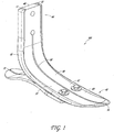
- FIGURES 1-5 illustrate one example of an overmould attachment 10 coupleable to a foot plate 40 of a prosthetic foot 100.
- the foot plate 40 generally can have a toe end 42 and an ankle end 44, as well as a toe surface or edge 46, an ankle surface or edge 48, and medial and lateral side surfaces or edges 50 extending from the toe surface 46 to the ankle surface 48.
- the medial and/or lateral side surfaces or edges 50 extend generally linearly (e.g., do not curve outward in a transverse direction to the longitudinal axis of the foot 100), or the foot plate 40 is generally planar, between the toe end 42 and the ankle end 44 along at least a portion of their length.
- the medial and or lateral side surfaces or edges 50 extend in a generally curved manner (e.g., curved in the medial-lateral direction and/or curved in the anterior-posterior direction) along at least a portion of their length between the toe end 42 and the ankle end 44.
- the foot plate 40 can also have a top surface 52 and a bottom surface 54 opposite the top surface 52.
- the overmould attachment 10 is coupled to at least the toe surface 46 of the foot plate 40 of the prosthetic foot 100.
- the overmould attachment 10 can be removably coupled to the foot plate 40 of the prosthetic foot 100.
- the overmould attachment 10 is coupled to the toe surface 46 and all along the entire length of the side surfaces 50 of the foot plate 40.
- the overmould attachment 10 has portions 12 that extend at least partially over the ankle surface 48 of the foot plate 40.
- the portions 12 of the overmould attachment 10 that extend at least partially over the ankle surface 48 help to couple the overmould attachment 10 to the foot plate 40.
- the overmould attachment 10 extends at least partially over the top surface 52 of the foot plate and at least partially over the bottom surface 54 of the foot plate.
- the overmould attachment 10 extends at least partially over the top surface 52 of the foot plate. In some examples, the overmould attachment 10 extends at least partially over the bottom surface 54 of the foot plate. In some examples, the prosthetic foot 100 can have a heel plate 70 disposed below (e.g., coupled to) the bottom surface 54 of the foot plate 40, extending away from the toe end 42. In one example, overmould attachment 10 is not coupled to the heel plate 70. In some examples, the overmould attachment 10 does not contact the heel plate 70.
- the foot plate 40 has a lengthwise split 56, beginning at the toe end 42 of the foot plate and extending at least part of the length of the foot plate 40, that divides the foot plate 40, resulting in a medial portion 58 and a lateral portion 60.
- the lengthwise split 56 does not span the entire length of the foot plate 40, resulting in an undivided foot plate at the ankle end 44 of the foot plate 40.
- the overmould attachment 10 will have a corresponding split 14 at the toe end 42.
- the splits 56 and 14 in the foot plate 40 and the overmould attachment 10 allow the medial and lateral portions 58 and 60 to flex at least somewhat independently, improving functional properties of the prosthetic foot during rollover or during use on different surfaces (e.g., on uneven terrain).
- the overmould attachment 10 advantageously changes the shape of the foot plate 40.
- the overmould attachment 10 changes the width of the foot plate 40.
- the overmould attachment 10 changes the length of the foot plate 40.
- the overmould attachment 10 advantageously changes the shape of the foot plate 40 to make it more like the shape of a natural human foot (e.g., to include a sandal toe slot).
- the overmould attachment 10 advantageously changes the shape of the foot plate 40 to improve stability characteristics of the prosthetic foot 100.
- the overmould attachment 10 advantageously changes the shape of the prosthetic foot 100 to improve functional characteristics of the prosthetic foot 100 during rallover.
- the altered shape of the foot plate 40 allows the prosthetic foot 100 to be used with a shoe or other footwear without needing a cosmetic cover over.
- the overmould attachment 10 shown in FIGURES 1-5 removably couples to a foot plate 40 of a prosthetic foot 100.
- the overmould attachment 10 is coupled or removably coupled to the foot plate 40 using at least one clip mechanism.
- the overmould attachment 10 is coupled or removably coupled to the foot plate 40 using a series of clips.
- the overmould attachment 10 is coupled or removably coupled to the foot plate 40 using glue or epoxy.
- the overmould attachment 10 is coupled or removably coupled to the foot plate 40 using magnetic force.
- the overmould attachment 10 is coupled to the foot plate 40 using a series of complementary magnets located at corresponding locations of the overmould attachment 10 and the foot plate 40. In still other examples, the overmould attachment 10 is coupled to the foot plate 40 using elastic properties of at least one part of the overmould attachment 10. In some examples, the overmould attachment 10 is coupled to the foot plate 40 using any method of coupling known in the art. In some examples, the overmould attachment 10 is coupled to the foot plate 40 using any combination of any of the aforementioned coupling mechanisms.
- the overmould attachment 10 is made of a polymer or plastic-like material or a compressible material. In some examples, the overmould attachment 10 is the same stiffness as the foot plate 40. In some examples, the overmould attachment 10 is cheaper and easier to manufacture than the foot plate 40. In some embodiments, the overmould attachment 10 protects the foot plate 40 of the prosthetic foot 100 from damage due to everyday wear and tear.
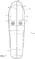
- FIGURES 6-9 illustrate another embodiment of an overmould attachment 210 coupleable to a foot plate 240 of a prosthetic foot 200.
- the foot plate 240 generally can have a toe end 242 and an ankle end 244, as well as a toe surfaces or edge 246, an ankle surface or edge 248, and medial and lateral side surfaces or edges 250 extending from the toe surface 246 to the ankle surfaces 248.
- the medial and/or lateral side surfaces or edges 250 extend generally linearly between the toe end 242 and the ankle end 244 along at least a portion of their length.
- the medial and or lateral side surfaces or edges 250 extend in a generally curved manner along at least a portion of their length between the toe end 242 and the ankle end 244.
- the foot plate 240 can also have a top surface 252 and a bottom surface 254 opposite the top surface 252.
- the overmould attachment 210 is coupled to the toe surface 246 of the foot plate 240 and along the side surfaces 250 of the foot plate 240 until about the portion 262 of the foot plate 240 where the foot plate 240 curves.
- the overmould attachment 210 would extend along the side surfaces 250 of the foot plate 240 past the curved portion 262, with the overmould attachment 210 curving to match the curve of the side surfaces 250.
- the overmould attachment would extend along the side surfaces 250 of the foot plate and stop before the curved portion 262.
- the overmould attachment 210 extends at least partially over the top surface 252 of the foot plate 240 and at least partially over the bottom surface 254 of the foot plate 240. In some examples, the overmould attachment 210 extends at least partially over the top surface 252 of the foot plate 240. In some examples, the overmould attachment 210 extends at least partially over the bottom surface 254 of the foot plate 240. In some examples, the prosthetic foot 200 can have a heel plate 270 disposed below (e.g., coupled to) the bottom surface 254 of the foot plate 240, extending away from the toe end 242. In one example, the overmould attachment 10 is not coupled to the heel plate 270. In some examples, the overmould attachment 10 does not contact the heel plate 270.
- the foot plate 240 has a lengthwise split 256, beginning at the toe end 242 of the foot plate and extending at least part of the length of the foot plate 240, that divides the foot plate 240, resulting in a medial portion 258 and a lateral portion 260.
- the lengthwise split 256 does not span the entire length of the foot plate, resulting in an undivided foot plate at the ankle end 244 of the foot plate 240.
- the attachment 210 will have a corresponding split 214 at the toe end 242.
- the splits 256 and 214 in the foot plate 240 and the overmould attachment 210 allow the medial and lateral portions 258 and 260 to flex at least somewhat independently, improving functional properties of the prosthetic foot during rollover and to accommodate use of the foot on different terrain.
- the overmould attachment 210 advantageously changes the shape of the foot plate 240.
- the overmould attachment 210 changes the width of the foot plate 240.
- the overmould attachment 210 changes the length of the foot plate 240.
- the overmould attachment 210 advantageously changes the shape (e.g., contour) of the foot plate 240 to make it more like the shape of a natural human foot (e.g., to include a sandal toe slot).
- the overmould attachment 210 advantageously changes the shape of the foot plate 240 to improve stability characteristics of the prosthetic foot 200 (e.g., by making the foot wider).
- the overmould attachment 210 advantageously changes the shape of the foot plate 240 to improve functional characteristics of the prosthetic foot 200 during rollover.
- the altered shape of the foot plate 240 allows the prosthetic foot 200 to be used with a shoe or other foot wear without needing a cosmetic cover over.
- the overmould attachment 210 shown in FIGURES 6-9 can be removably coupled to a foot plate 240 of a prosthetic foot 200.
- the overmould attachment 210 is coupled or removably coupled to the foot plate 240 using at least one clip mechanism.
- the overmould attachment 210 is coupled or removably coupled to the foot plate 240 using a series of clips.
- the overmould attachment 210 is coupled or removably coupled to the foot plate 240 using glue or epoxy.
- the overmould attachment 210 is coupled or removably coupled to the foot plate 240 using magnetic force.
- the overmould attachment 210 is coupled to the foot plate 240 using a series of complementary magnets located at corresponding locations of the overmould attachment 210 and the foot plate 240. In still other examples, the overmould attachment 210 is coupled to the foot plate 240 using elastic properties of at least one part of the overmould attachment 210. In some examples, the overmould attachment 210 is coupled to the foot plate 240 using any method of coupling known in the art. In some examples, the overmould attachment 210 is coupled to the foot plate 240 using any combination of any of the aforementioned coupling mechanisms.
- the overmould attachment 210 is made of a polymer or plastic-like material or a compressible material. In some examples, the overmould attachment 210 is the same stiffness as the foot plate 240. In some examples, the overmoutd attachment 210 is cheaper and easier to manufacture than the foot plate 240. In some examples, the overmould attachment 210 protects the foot plate 240 of the prosthetic foot 200 from damage due to everyday wear and tear.
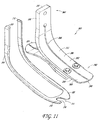
- FIGURES 10-13 illustrate another example of an overmould attachment 310 coupleable to a foot plate 340 of a prosthetic foot 300.
- the foot plate 340 generally can have a toe end 342 and an ankle end 344, as well as a toe surface 346, an ankle surface 348, and medial and lateral side surfaces 350 extending from the toe surface 346 to the ankle surface 348.
- the medial and/or lateral side surfaces or edges 350 extend generally linearly between the toe end 342 and the ankle end 344 along at least a portion of their length.
- the medial and or lateral side surfaces or edges 350 extend in a generally curved manner along at least a portion of their length between the toe end 342 and the ankle end 344.
- the foot plate 340 can have a top surface 352 and a bottom surface 354 opposite the top surface 352.
- the example of an overmould attachment 310 shown in FIGURES 10-13 is coupled or removably coupled to the toe surface 346 of foot plate 340 and along the side surfaces 350 of the foot plate 340 A of a prosthetic foot 300.
- the overmould attachment 310 is coupled or removably coupled along the entire side surfaces 350 of the foot plate 340.
- the overmould attachment 310 has portions 312 that extend at least partially over the ankle surface 348 of the foot plate 340. In some examples, the portions 312 of the overmould attachment 310 that extend at least partially over the ankle surface 348 help to couple the overmould attachment 310 to the foot plate 340. In some examples, the overmould attachment 310 extends at least partially over the top surface 352 of the foot plate 340 and at least partially over the bottom surface 354 of the foot plate 340. In some examples, the overmould attachment 310 extends at least partially over the top surface 352 of the foot plate 340.
- the overmould attachment 310 extends at least partially over the bottom surface 354 of the foot plate 340.
- the prosthetic foot 300 can have a heel plate 370, connected to the bottom surface 354 of the foot plate 340, extending away from the toe end 342.
- the overmould attachment 10 is not coupled to the heel plate 370. In some examples, the overmould attachment 10 does not contact the heel plate 370.
- the foot plate 340 has a lengthwise split, 356 beginning at the toe end 342 of the foot plate and extending at least part of the length of the foot plate 340, that divides the foot plate 340, resulting in a medial portion 358 and a lateral portion 360.
- the lengthwise split 356 does not span the entire length of the foot plate, resulting in an undivided foot plate at the ankle end 344 of the foot plate 340.
- the attachment 310 can have a corresponding split (not shown) at the toe end 342. The splits in the foot plate and the attachment can allow the medial and lateral portions 358 and 360 to flex at least somewhat independently, improving functional properties of the prosthetic foot during rollover and when used on uneven terrain.
- the overmould attachment 310 is a single piece that advantageously changes the shape of the foot plate 340.
- the overmould attachment 310 includes a portion 314 that extends the length of the toe of the foot plate 340, wherein the extended portion 314 includes a cutout section 316 that divides the extended portion 314 into a medial lobe 318 and a lateral lobe 320.
- the cutout or slot 316 is generally U-shaped and sized to receive a strap of a sandal, flip-flop or similar footwear (e.g., the slot 316 provides a sandal toe features).
- both the medial lobe 318 and lateral lobe 320 can have a width.
- the lateral lobe 320 has a width greater than the width of the medial lobe 318.
- the medial lobe 318 has a width greater than the width of the lateral lobe 320.
- the medial lobe 318 and lateral lobe 320 have equal or approximately equal widths (e.g., the slot 316 can be located generally midway along the width of the foot 300).
- the respective widths of the medial lobe 318 and lateral lobe 320 result in a stiffness for the medial lobe 318 and lateral lobe 320, wherein varying the widths of the medial lobe 318 and lateral lobe 320 results in varying the stiffness of the medial lobe 318 and lateral lobe 320.
- the characteristics of the medial lobe 318 and lateral lobe 320 result in improved rollover during use of the prosthetic foot 300 coupled to the overmould attachment 310.
- this extended portion 314 including a cutout 316 allows the user to use the prosthetic foot 300 in combination with sandal-type shoes or other types of footwear without also having to use a cosmetic foot cover.
- the overmould attachment 310 changes the width of the foot plate 340. In some examples, the overmould attachment 310 changes the length of the foot plate 340. In some examples, the overmould attachment 310 advantageously changes the shape of the foot plate 340 to make it more like the shape of a natural human foot (e.g., to include a sandal toe slot). In some examples, the overmould attachment 310 advantageously changes the shape of the foot plate 340 to improve stability characteristics of the prosthetic foot 300. In some examples, the overmould attachment 310 advantageously changes the shape of the foot plate 340 to improve functional characteristics of the prosthetic foot 300 during rollover.
- the overmould attachment 310 shown in FIGURES 10-13 can be removably coupled to a foot plate 340 of a prosthetic foot 300.
- the overmould attachment 310 is coupled or removably coupled to the foot plate 340 using at least one clip mechanism.
- the overmould attachment 310 is coupled or removably coupled to the foot plate 340 using a series of clips.
- the overmould attachment 310 is coupled or removably coupled to the foot plate 340 using glue or epoxy.
- the overmould attachment 310 is coupled or removably coupled to the foot plate 340 using magnetic force.
- the overmould attachment 310 is coupled to the foot plate 340 using a series of complementary magnets located at corresponding locations of the overmould attachment 310 and foot plate 340. In still other examples, the overmould attachment 310 is coupled to the foot plate 340 using elastic properties of at least one part of the overmould attachment 310. In some examples, the overmould attachment 310 is coupled to the foot plate 340 using any method of coupling known in the art. In some embodiments, the overmould attachment 310 is coupled to the foot plate 340 using any combination of any of the aforementioned coupling mechanisms.
- the overmould attachment 310 is made of a polymer or plastic-like material or a compressible material. In some examples, the overmould attachment 310 is the same stiffness as the foot plate 340. In some examples, the overmould attachment 310 is cheaper and easier to manufacture than the foot plate 340. In some examples, the overmould attachment 310 protects the foot plate 340 of the prosthetic foot 300 from damage due to everyday wear and tear.
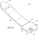
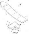
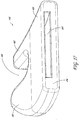
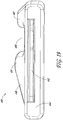
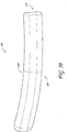
- FIGURES 14-20 illustrates one embodiment of a toe attachment 410 coupleable to a foot plate 440 of a prosthetic foot 400.
- the foot plate 440 can be generally planar (e.g., generally flat) and have a toe end 442 and an ankle end 444, as well as a toe surfaces 446, an ankle surface 448, and medial and lateral side surfaces 450 extending from the toe surface 446 to the ankle surface 448.
- the toe attachment 410 is coupled to the toe end 442 of a foot plate 440 for a prosthetic foot 400.
- the toe attachment 410 is removably coupleable to the foot plate 440.
- the toe attachment 410 can have a cavity 412 on a rear surface 414, shown in FIGURES 17-19 , wherein the cavity can receive the toe end 442 of a foot plate 440 such that the toe attachment 410 is coupled or removably coupled to the toe end 442 of the foot plate 440.
- the toe attachment 410 is coupled or removably coupled to a foot plate 440 using at least one clip.
- the toe attachment 410 is coupled or removably coupled to a foot plate 440 using glue or epoxy.
- the toe attachment 410 is coupled or removably coupled to a foot plate 440 using magnetic force.
- the toe attachment 410 is coupled to the foot plate 440 using any method of coupling known in the art.
- the toe attachment 410 is coupled to the foot plate 440 using any combination of any of the aforementioned coupling mechanisms.
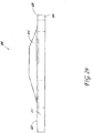
- the toe attachment 410 can have a top surface 418 and a bottom surface 420. In some embodiments, the top surface 418 and the bottom surface 420 are substantially parallel. In some embodiments, as shown in FIGURE 20 , the top surface 418 and the bottom surface 420 have a slight upward curve as they move away from rear surface 414. In some embodiments, the toe attachment 410 can have a cutout or slot 416 that extends from the top surface 418 to the bottom surfaces 420 that divides the toe attachment 410 into a medial lobe 422 and a lateral lobe 424.
- the cutout or slot 416 is generally U-shaped and sized to receive a strap of a sandal, flip-flop or similar footwear (e.g., the slot 416 can provide a sandal toe feature).
- the cutout 416 resulting in a medial lobe 422 and lateral lobe 424 gives the toe attachment 410 a more anatomical appearance.
- the more anatomical appearance is a "sandal toe" appearance.
- both the medial lobe 422 and lateral lobe 424 can have a width.
- the medial lobe 422 has a width greater than the width of the lateral lobe 424.
- the lateral lobe 424 has a width greater than the width of the medial lobe 422.
- the medial lobe 422 and lateral lobe 424 have equal or approximately equal widths (e.g., the slot 416 can be located generally midway along the width of the foot 400).
- the respective widths of the medial lobe 422 and lateral lobe 424 result in a stiffness for the medial lobe 422 and lateral lobe 424, wherein varying the widths of the medial lobe 422 and lateral, lobe 424 results in varying the stiffness of the medial lobe 422 and lateral lobe 424.
- this stiffness at the medial lobe 422 and lateral lobe 424 improve the functional characteristics of the prosthetic foot 400 during rollover. Additionally, when coupled to a foot plate 440, the toe attachment 410 facilitates use of the prosthetic foot 400 with sandal-type shoes or other footwear without the use a cosmesis.
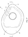
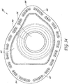
- FIGURES 21-25 illustrate one embodiment of a seal cover 500 for a cosmetic cover (e.g., cosmesis) for a prosthetic foot.
- the seal cover 500 generally has the shape of the cross-section of a human ankle.
- the seal cover 500 generally has the shape of the ankle opening of a cosmetic cover for a prosthetic foot.
- the seal cover 500 generally can have an inner portion 512 and an outer portion 514.
- the inner portion 512 and the outer portion 514 are made of different materials.
- the inner portion 512 is a membrane made of a flexible material.
- the flexible material is elastic.
- the outer portion 514 is a frame made of plastic (e.g., a hard plastic). However, other suitable materials can be used.
- the inner portion 512 and the outer portion 514 can be made of the same material.
- the inner portion 512 can have a circular opening 516 that can fit over (e.g., engage) a portion of a prosthetic foot 542 or prosthetic component (e.g., pylon) 544 or 546, resulting in a substantially watertight connection 560 between the inner portion 512 and the prosthetic foot 542 or prosthetic foot component 544 or 546.
- the circular opening 516 can have an O-ring 518.
- the opening 516 of the inner portion 12 fits over (e.g., engages) an adaptor of a prosthetic foot.
- the opening 516 of the inner portion 512 fits around (e.g., engages) a shank of a prosthetic foot.
- the opening 516 of the inner portion 512 engages a collar adaptor located on a prosthetic foot (e.g., the collar adaptor 700 shown in FIG. 31 and described below), the collar adaptor having a groove that can receive the 0-ring 518 of the opening 516.
- a prosthetic foot e.g., the collar adaptor 700 shown in FIG. 31 and described below
- the collar adaptor having a groove that can receive the 0-ring 518 of the opening 516.
- the connection 560 between the inner portion 512 and the prosthetic foot is substantially watertight.
- the outer portion 514 can have a top surface 520, a bottom surface 522, and an edge 524 defining a perimeter 526.
- the edge 524 and the top surface 520 form a corner 528 around the perimeter 526 of the outer portion 514, and, in some embodiments, this corner 528 is rounded off.
- the top surface 520 is substantially flat.
- the perimeter 526 has generally the shape of the ankle opening of a cosmetic cover 540 for a prosthetic foot 542.
- the outer portion 514 can engage a cosmetic cover 540 for a prosthetic foot 542.
- the outer portion 514 can removably engage a cosmetic cover 540 for a prosthetic foot 542.
- the bottom surface 522 can engage a cosmetic cover 540 for a prosthetic foot 542.
- the bottom surface 522 has a series of protrusions 530 that can removably engage complementary cavities on the cosmetic cover 540.
- the bottom surface 522 can engage a cosmetic cover 540 such that the connection 550 between the outer portion 514 and the cosmetic cover is substantially watertight.
- glue or epoxy can be used at the connection 550 between the outer portion 514 and the cosmetic cover to improve the seal of the connection 550.
- the series of protrusions 530 is generally located around the perimeter 526 of the outer portion 514. In some embodiments, the series of protrusions 530 generally located around the perimeter 526 of the outer portion 514 are offset in from the edge 524 of the outer portion 514 such that when the outer portion 514 is engaged with a cosmetic cover, the edge 524 of the outer portion 514 is substantially flush with an outer surface of the cosmetic cover 540. In some embodiments, the protrusions 530 mate with corresponding recess openings or slots on a surface of the opening of the cosmetic cover 540. In some embodiments, the protrusions 530 are equally spaced around the perimeter 526 of the outer portion 514.
- the spacing between the protrusions 530 can vary.
- the series of protrusions 530 can have any number of protrusions. In some embodiments, the number of protrusions 530 is between 1 and 30. In some embodiments, there are about 15-20 protrusions in the series of protrusions 530. In some embodiments, there are 18 protrusions in the series of protrusions 530.
- a protrusion 530 can have a height, a length, a width, and a first and second cross-sectional faces 532, the cross-sectional faces 532 having a shape comprising a body 534 having a rectangular cross-section and a head 536 having an inverted triangular cross-section.
- the head 536 is located on the portion of the protrusion 530 farthest away from the bottom surface 522.
- the triangular portion of the first and second cross-sectional faces 532 is angled inwards towards the opposite cross-sectional face.
- the triangular head 536 has a width greater than the width of the rectangular body 534 such that the width of the triangle extends beyond the width of the rectangle.
- the height of a protrusions 530 is defined by the distance from the bottom surface 522 to the tip of the head 534 of the protrusion 530. In some embodiments, all protrusions 530 have equal heights. In some embodiments, the protrusions 530 have varying heights. In some embodiments, the height of a single protrusion 530 can be between about 0.1 cm to about 10 cm. In some embodiments, the height of a single protrusion 530 can be between about 0.1 cm to about 3 cm. The length of a protrusion 530 is defined by the distance from the first cross-sectional face to the second cross-sectional face. The length of a single protrusion 530 can vary between about 0.1 cm to about 10 cm.
- the length of a single protrusion 530 can be between about 0.1 cm to about 3 cm. In some embodiments, all protrusions 530 have generally equal lengths. In some embodiments, protrusions 530 can have varying lengths. In some embodiments, the protrusions 530 are generally straight between the first and second cross-sectional faces 532. In some embodiments, the protrusions 530 curve between the first and second cross-sectional faces 532. In some embodiments, the protrusions 530 curve between the first and second cross-sectional faces 532 such that they run generally parallel to the perimeter 526 of the outer portion 514.
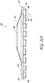
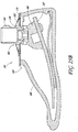
- FIGURE 25B illustrates one embodiment of a seal cover 500 engaged with a cosmetic cover 540 and fitted around (e.g., engaged with) a prosthetic foot system.
- the outer portion 514 of the seal cover 500 is engaged with the cosmetic cover 540 such that the connection 550 between the outer portion 514 and the cosmetic cover 540 is substantially watertight.
- the inner portion 512 of the seal cover 500 fits around (e.g., engages) a component 542, 544 or 546 of a prosthetic foot system such that the connection 560 between the inner portion 512 and the prosthetic foot system is substantially watertight.
- the inner portion 512 of the seal cover 500 fits around (e.g., engages) a collar adaptor (e.g., the collar adaptor 700 shown in FIG. 31 and described below) located on or around a component of a prosthetic foot system, wherein the collar adaptor can have a groove to receive the inner portion 512.
- the inner portion 512 can have varying shapes or designs.
- FIGURES 26-30 illustrate one embodiment of a seal cover 600 for a cosmetic cover for a prosthetic foot.
- the seal cover 600 generally has the shape of the cross-section of a human ankle.
- the seal cover 600 generally has the shape of the ankle opening of a cosmetic cover for a prosthetic foot.
- the seal cover 600 generally can have an inner portion 612 and an outer portion 614.
- the inner portion 612 and the outer portion 614 are made of different materials.
- the inner portion 612 is a membrane made of a flexible material.
- the flexible material is elastic.
- the outer portion 614 is a frame made of plastic (e.g., hard plastic). However, other suitable materials can be used.
- the inner portion 612 and the outer portion 614 can be made of the same material.
- the inner portion 612 can have a circular opening 616 that can fit over (e.g., engage) a portion of a prosthetic foot or prosthetic component (e.g., pylon), resulting in a substantially watertight connection between the inner portion 612 and the prosthetic foot.
- the circular opening 616 can have an O-ring 618.
- the opening 616 of the inner portion 612 fits over (e.g., engages) an adaptor of a prosthetic foot.
- the opening 616 of the inner portion 612 fits around (e.g., engages) a shank of a prosthetic foot.
- the opening 616 of the inner portion 612 engages a collar adaptor located on a prosthetic foot (e.g., the collar adaptor 700 shown in FIG. 31 and described below), the collar adaptor having a groove that can receive the O-ring 618 of the opening 616.
- a collar adaptor located on a prosthetic foot
- the collar adaptor having a groove that can receive the O-ring 618 of the opening 616.
- the connection between the inner portion 612 and the prosthetic foot is substantially watertight.
- the outer portion 614 can have a top surface 620, a bottom surface 622, and an edge 624 defining a perimeter 626.
- the edge 624 and the top surface 620 form a corner 628 around the perimeter 626 of the outer portion 614, and, in some embodiments, this corner 628 is rounded off.
- the top surface 620 is substantially flat.
- the perimeter 626 has generally the shape of the ankle opening of a cosmetic cover for a prosthetic foot.
- the outer portion 614 can engage a cosmetic cover for a prosthetic foot.
- the outer portion 614 can removably engage a cosmetic cover for a prosthetic foot.
- the bottom surface 622 can engage a cosmetic cover for a prosthetic foot.
- the bottom surface 622 can have a first lip 630 and a second lip 640, wherein the first lip 630 is closer to the perimeter 626 of the outer portion 614 than the second lip 640, and whereby the two lips 630 and 640 define a cavity or slot 650 between them.
- the first and second lips 630 and 640 can removably engage a cosmetic cover for a prosthetic foot.
- the first and second lips 630 and 640 are located generally near the perimeter 626 of the bottom surface 622.
- the first lip 630 is a continuous projection that forms a single continuous ridge that runs generally parallel to the perimeter 626 of the outer portion 614.
- the second lip 640 is a continuous projection that forms a single continuous ridge that runs generally parallel to the perimeter 626 of the outer portion 614.
- the first and second lips 630 and 640 run generally parallel to the perimeter 626 of the outer portion 614.
- the continuous first and second lips 630 and 640 define a cavity, slot or channel 650 that runs substantially parallel to the perimeter 626 of the outer portion 614 and that can removably receive at least a portion of a cosmetic cover for a prosthetic foot.
- the first lip 630 has an outer surface 632 and an inner surface 634.
- the outer surface 632 of the first lip 630 is generally perpendicular to the top surface 620 of the outer portion 614.
- the outer surface 632 is contiguous with the edge 624 of the outer portion 614 such that it is effectively a continuation of the edge 624 of the outer portion 614.
- the inner surface 634 of the first lip 630 is at an angle relative to the outer surface 632 such that the first lip 630 becomes narrower as it moves away from the bottom surface 622 of the outer portion 614.
- the second lip 640 has an outer surface 642 and an inner surface 644.
- the outer surface 642 of the second lip 640 is generally perpendicular to the top surface 620 of the outer portion 614.
- the outer surface 642 of the second lip 640 is generally parallel to the outer surface 632 of the first lip 630.
- the inner surface 644 of the second lip 640 has a semi-circle or round protrusion 646 on the portion of the surface 644 that is farthest away from the bottom surface 622 of the outer portion 614.
- the portion of the inner surface 644 closest to the bottom surface 622 of the outer portion 614 is at an angle relative to the outer surface 642 of the second lip 640.
- the semi-circle or round protrusion 646 on the inner surface 644 of the second lip 640 can removably engage a corresponding feature on a cosmetic cover for a prosthetic foot.
- the second lip 640 can deflect towards first lip 630 during the process of engaging the seal cover to the cosmetic cover, and then return to the original un-deflected position to engage the cosmetic cover.
- the connection between the outer portion 614 and the cosmetic cover is substantially watertight.
- glue or epoxy may be used at the point of attachment to achieve a greater degree of waterproofing.
- FIGURES 32-37 illustrate one embodiment of a seal cover 800 for a cosmetic cover for a prosthetic foot.
- the seal cover 800 generally has the shape of the cross-section of a human ankle.
- the seal cover 800 generally has the shape of the ankle opening of a cosmetic cover for a prosthetic foot.
- the seal cover 800 generally can have an inner portion 812 and an outer portion 814.
- the inner portion 812 and the outer portion 814 are made of different materials.
- the inner portion 812 is a membrane made of a flexible material.
- the flexible material is elastic.
- the outer portion 814 is a frame made of plastic (e.g., hard plastic).
- the inner portion 812 and the outer portion 814 can be made of the same material.
- the inner portion 812 can have a circular opening 816 that can fit over (e.g., engage) a portion of a prosthetic foot or prosthetic component (e.g., pylon), resulting in a substantially watertight connection between the inner portion 812 and the prosthetic foot.
- the circular opening 816 can have an O-ring 818.
- the opening 816 of the inner portion 812 fits over (e.g., engages) an adaptor of a prosthetic foot.
- the opening 816 of the inner portion 812 fits around (e.g., engages) a shank of a prosthetic foot.
- the opening 816 of the inner portion 812 engages a collar adaptor located on a prosthetic foot (e.g., the collar adaptor 700 shown in FIG. 31 and described below), the collar adaptor having a groove that can receive the O-ring 818 of the opening 816.
- the inner portion 812 can have excess material (e.g., be oversized) such that when the opening 816 is engaged with a portion of a prosthetic foot or prosthetic component, the inner portion 816 is not taut or rigid.
- the excess material (or oversized configuration) of the inner portion 812 can define one or more folds 870 in the inner portion 812.
- this excess material that defines one or more folds 870 allows for greater flexibility of the inner portion 812 when it is engaged with a prosthetic foot or prosthetic component. In some embodiments, when the opening 816 is engaged with the corresponding portion of a prosthetic foot, the connection between the inner portion 812 and the prosthetic foot is substantially watertight.
- the outer portion 814 can have a top surface 820, a bottom surface 822, and an edge 824 defining a perimeter 826.
- the edge 824 and the top surface 820 form a corner 828 around the perimeter 826 of the outer portion 814, and, in some embodiments, this corner 828 is rounded off.
- the top surface 820 is substantially flat, though in other embodiments it can have other suitable configurations (e.g., curved, concave, convex).
- the perimeter 826 has generally the shape of the ankle opening of a cosmetic cover 840 for a prosthetic foot 842.
- the outer portion 814 can engage a cosmetic cover 840 for a prosthetic foot 842.
- the outer portion 814 can removably engage a cosmetic cover 840 for a prosthetic foot 842.
- the bottom surface 822 can engage a cosmetic cover 840 for a prosthetic foot 842.
- the outer portion 814 can engage a cosmetic cover 840 for a prosthetic foot 842 in the manner described and shown with respect to outer portion 514 and cosmetic cover 540 in FIGURES 21-25 , via a series of protrusions 830 on the bottom surface 822 that can removably engage one or more complementary cavities, recesses or slots on the cosmetic cover 840.
- the series of protrusions 830 on seal cover 800 is substantially similar to the series of protrusions 530 on seal cover 500 as described above for FIGURES 21-25 .
- the outer portion 814 can fit over or engage a cosmetic cover 840 for a prosthetic foot 842 in the manner described and shown with respect to outer portion 614 and in FIGURES 26-30 , using a first and second lip to engage the cosmetic cover 840 (not shown for the embodiment of the seal cover 800).
- the first and second lips are substantially similar to the first lip 630 and second lip 640 on seal cover 600 described above for FIGURES 26-30 .
- FIGURE 37 illustrates one embodiment of a seal cover 800 engaged with a cosmetic cover 840 and fitted around (e.g., engaged with) a prosthetic foot system.
- the outer portion 814 of the seal cover 800 is engaged with the cosmetic cover 840 such that the connection 850 between the outer portion 814 and the cosmetic cover 840 is substantially watertight.
- the inner portion 812 of the seal cover 800 fits around (e.g., engages) a component, for example 842 or 844, of a prosthetic foot system such that the connection 860 between the inner portion 812 and the prosthetic foot system is substantially watertight.
- the inner portion 812 of the seal cover 800 fits around (e.g., engages) a collar adaptor (e.g., the collar adaptor 700 shown in FIG. 31 and described below) located on or around a component of a prosthetic foot system, wherein the collar adaptor can have a groove to receive the inner portion 812.
- the inner portions 812 has excess material (or is oversized) resulting in at least one fold 870, wherein the at least one fold 870 allows for greater flexibility in the inner portion 812 and the connection 860 between the inner portion 812 and the prosthetic foot system.
- the inner portion 812 can have varying shapes or designs, including one or more folds 870.
- FIGURE 31 illustrates one embodiment of a collar adaptor 700 for a prosthetic foot system that can receive (e.g., engage) a seal cover, such as the seal cover 500 or seal cover 600.
- the collar adaptor 700 can have a groove 710 that can receive (e.g., engage) at least a portion of a seal cover.
- the groove 710 can receive (e.g., engage) an inner portion of a seal cover.
- the groove 710 can receive (e.g., engage) an O-ring of an inner portion of a seal cover.
- the groove 710 is circumferential.
- the groove 710 can have a semi-circular cross-section.
- the collar adaptor 700 can receive (e.g., engage) at least a portion of a seal cover such that the connection between the collar adaptor 700 and the seal cover is substantially watertight.
- the collar adaptor 700 can fit on, over, or around (e.g., engage) a portion or component of a prosthetic foot system, such as a proximal portion of a foot plate of the prosthetic foot or a pylon attached to the prosthetic foot.
- the collar adaptor 700 can fit on, over, or around (e.g., engage) a portion or component of a prosthetic foot system via an aperture in the collar adaptor 700.
- the aperture can have a substantially rectangular shape. In some embodiments, the aperture can have a substantially circular shape.
- the aperture can have a shape such that the collar adaptor 700 can fit on, over, or around a portion or component of a prosthetic foot system (e.g., the shape of the aperture generally coincides with a cross-sectional shape of the component to which the adaptor is coupled).
- the collar adaptor 700 can fit on, over, or around (e.g., engage) the shank, pylon, pyramid adaptor, foot plate, or any other portion or component of a prosthetic foot system.
- the collar adaptor 700 can fit on, over, or around (e.g., engage) at least a portion or component of a prosthetic foot system such that the connection between the collar adaptor 700 and the at least a portion of the prosthetic foot system is substantially watertight.
- the collar adaptor 700 can fit on, over, or around (e.g., engage) a portion or component of a prosthetic foot system and can removably receive (e.g., engage) at least a portion (i.e., an inner portion or O-ring) of a seal cover resulting in a substantially watertight connection between the prosthetic foot system and the seal cover.
- the collar adaptor 700 can be integrated into (e.g., manufactured as a part of) at least a portion of a prosthetic foot system, such that the portion of the prosthetic foot system can have a groove 710 that can receive (e.g., engage) a portion of a seal cover.
- the terms “generally parallel” and “substantially parallel” refer to a value, amount, or characteristic that departs from exactly parallel by less than or equal to 15 degrees, 10 degrees, 5 degrees, 3 degrees, 1 degree, 0.1 degree, or otherwise.
Landscapes
- Health & Medical Sciences (AREA)
- Transplantation (AREA)
- Life Sciences & Earth Sciences (AREA)
- Animal Behavior & Ethology (AREA)
- Engineering & Computer Science (AREA)
- Biomedical Technology (AREA)
- Heart & Thoracic Surgery (AREA)
- Vascular Medicine (AREA)
- Cardiology (AREA)
- Oral & Maxillofacial Surgery (AREA)
- General Health & Medical Sciences (AREA)
- Public Health (AREA)
- Veterinary Medicine (AREA)
- Orthopedic Medicine & Surgery (AREA)
- Prostheses (AREA)
- Footwear And Its Accessory, Manufacturing Method And Apparatuses (AREA)
Claims (12)
- Pied prothétique (400, 542), comprenant :un élément de pied allongé ayant une extrémité d'orteil (442) et une extrémité de cheville (444) ; etune fixation d'orteil (410) pouvant être couplée de manière amovible à l'élément de pied allongé et ayant une surface supérieure (418), une surface inférieure (420), une extrémité distale, une extrémité proximale, la fixation d'orteil définissant une fente (416) dans celle-ci et ayant une longueur plus courte qu'une longueur de l'élément de pied allongé,dans lequel la fixation d'orteil (410) est configurée pour s'accoupler de manière amovible seulement à l'extrémité d'orteil (442) de l'élément de pied allongé,dans lequel la fente (416) dans la fixation d'orteil s'étend à partir de la surface supérieure (418) jusqu'à la surface inférieure (420) en définissant un lobe médial (422) et un lobe latéral (424) de la fixation d'orteil (410)pouvant être couplée de manière amovible, la fente (416) étant configurée pour recevoir de manière amovible une lanière d'une sandale lorsque ladite sandale est couplée au pied prothétique (400), dans lequel la fixation d'orteil (410) possède une cavité (412) sur une surface arrière (414), et la cavité (412) est configurée pour recevoir l'extrémité d'orteil (442) de l'élément de pied allongé.
- Pied prothétique selon la revendication 1, dans lequel la fente (416) est généralement en forme de U.
- Pied prothétique selon la revendication 1, dans lequel la fixation d'orteil (410) peut être fixée à au moins une surface d'orteil distale et aux surfaces médiale et latérale de l'élément de pied allongé pour modifier une forme du pied prothétique (400) en augmentant au moins l'une d'une largeur et d'une longueur d'au moins une partie de l'élément de pied allongé.
- Pied prothétique selon la revendication 1, dans lequel le lobe médial (422) et le lobe latéral (424) de la fixation d'orteil (410) ont des largeurs différentes.
- Pied prothétique selon la revendication 4, dans lequel les largeurs différentes pour le lobe médial (422) et le lobe latéral (424) fournissent une rigidité variable du lobe médial (422) et du lobe latéral (424).
- Pied prothétique selon la revendication 1, dans lequel l'élément de pied allongé est une plaque de pied plane (440).
- Pied prothétique selon la revendication 1, dans lequel la surface supérieure (418) et la surface inférieure (420) de la fixation d'orteil (410) sont parallèles.
- Pied prothétique selon la revendication 1, dans lequel la surface supérieure (418) et la surface inférieure (420) de la fixation d'orteil (410) sont incurvées vers le haut en s'écartant de l'extrémité proximale de la fixation d'orteil (410).
- Pied prothétique selon la revendication 1, comprenant en outre un produit cosmétique dans lequel le pied prothétique est reçu, et une protection d'étanchéité (500, 600) pour le produit cosmétique comprenant :une partie intérieure (512, 612) constituée d'un matériau souple ayant une ouverture circulaire (516, 616) configurée pour s'engager avec au moins une partie du pied prothétique (542) ; etune partie extérieure (514, 614) ayant une surface supérieure (520, 620) et une surface inférieure (522, 622), la surface inférieure (522, 622) étant configurée pour s'engager avec le produit cosmétique ;grâce à quoi l'engagement entre la partie intérieure (512, 612) et le pied prothétique (542) et l'engagement entre la partie extérieure (514, 614) et le produit cosmétique sont étanches à l'eau.
- Pied prothétique selon la revendication 9, dans lequel la partie intérieure (512, 612) et la partie extérieure (514, 614) sont constituées de matériaux différents.
- Pied prothétique selon la revendication 9, dans lequel la surface inférieure (522) et la partie extérieure (514) comprennent en outre une série de protubérances (530) configurées pour s'engager de manière amovible avec une protection cosmétique du pied prothétique (542).
- Pied prothétique selon la revendication 9, dans lequel la surface inférieure (622) de la partie extérieure (614) comprend en outre une première lèvre (630) contiguë avec le bord de la partie extérieure (614) et une deuxième lèvre (640) parallèle à la première lèvre (630), dans lequel les première et deuxième lèvres (630, 640) sont configurées pour s'engager de manière amovible avec une protection cosmétique pour un pied prothétique.
Applications Claiming Priority (2)
| Application Number | Priority Date | Filing Date | Title |
|---|---|---|---|
| US201361764424P | 2013-02-13 | 2013-02-13 | |
| PCT/US2014/014939 WO2014126768A1 (fr) | 2013-02-13 | 2014-02-05 | Fixations de surmoulage pour pied prothétique |
Publications (3)
| Publication Number | Publication Date |
|---|---|
| EP2956094A1 EP2956094A1 (fr) | 2015-12-23 |
| EP2956094A4 EP2956094A4 (fr) | 2016-05-11 |
| EP2956094B1 true EP2956094B1 (fr) | 2017-10-11 |
Family
ID=51298007
Family Applications (1)
| Application Number | Title | Priority Date | Filing Date |
|---|---|---|---|
| EP14751312.1A Active EP2956094B1 (fr) | 2013-02-13 | 2014-02-05 | Fixations de surmoulage pour pied prothétique |
Country Status (5)
| Country | Link |
|---|---|
| US (2) | US20140228974A1 (fr) |
| EP (1) | EP2956094B1 (fr) |
| CN (1) | CN105188615B (fr) |
| BR (1) | BR112015019266A2 (fr) |
| WO (1) | WO2014126768A1 (fr) |
Cited By (1)
| Publication number | Priority date | Publication date | Assignee | Title |
|---|---|---|---|---|
| DE102020106788A1 (de) | 2020-03-12 | 2021-09-16 | Ottobock Se & Co. Kgaa | System zum Verkleiden zumindest einer Prothese |
Families Citing this family (8)
| Publication number | Priority date | Publication date | Assignee | Title |
|---|---|---|---|---|
| US10842653B2 (en) | 2007-09-19 | 2020-11-24 | Ability Dynamics, Llc | Vacuum system for a prosthetic foot |
| EP2956094B1 (fr) | 2013-02-13 | 2017-10-11 | Össur hf | Fixations de surmoulage pour pied prothétique |
| US9968467B2 (en) | 2015-04-27 | 2018-05-15 | Össur Iceland Ehf | Tapered flex plate for prosthetic foot |
| US10485680B2 (en) * | 2016-03-31 | 2019-11-26 | Nike, Inc. | Prosthetic blade attachment system |
| RU2751560C1 (ru) * | 2020-06-29 | 2021-07-14 | Общество с ограниченной ответственностью «МЕТИЗ ПРОИЗВОДСТВО» | Протез стопы с упругим соединением с адаптером |
| WO2023031637A1 (fr) * | 2021-09-01 | 2023-03-09 | Chabloz Orthopédie | Semelle interchangeable pour chaussures à talons hauts |
| EP4493128A1 (fr) * | 2022-03-17 | 2025-01-22 | Össur Iceland ehf | Protège-pied pour pied prothétique |
| WO2023237994A1 (fr) * | 2022-06-06 | 2023-12-14 | Össur Iceland Ehf | Ensemble protège-pied pour pied prothétique |
Family Cites Families (27)
| Publication number | Priority date | Publication date | Assignee | Title |
|---|---|---|---|---|
| US1452302A (en) * | 1922-02-16 | 1923-04-17 | Loven Carl | Stocking |
| US3062557A (en) | 1959-07-06 | 1962-11-06 | Dowty Seals Ltd | Sealing rings |
| GB2249939A (en) * | 1990-11-23 | 1992-05-27 | Clive Hollinshead | Shoe and shoe sole |
| US6071313A (en) * | 1991-02-28 | 2000-06-06 | Phillips; Van L. | Split foot prosthesis |
| US5653767A (en) * | 1992-11-17 | 1997-08-05 | Medonics, Llc | Prosthetic foot |
| US5653768A (en) * | 1994-01-21 | 1997-08-05 | Bruce Kania | Dual cantilevered leaf spring structure |
| DE19521147C1 (de) * | 1995-06-09 | 1996-12-05 | Bock Orthopaed Ind | Gelenkloses Prothesenfußteil |
| SE511893C2 (sv) | 1996-07-05 | 1999-12-13 | Pro Pel Ab | Anpassningsbar framfotsdel för en fotprotes; användning av en sådan framfotsdel i en inställbar fotprotes samt system avsett för individuellt anpassningsbara fotproteser |
| SE514554C2 (sv) | 1999-07-09 | 2001-03-12 | Gramtec Innovation Ab | Fotprotes |
| US6811571B1 (en) | 2000-05-02 | 2004-11-02 | Van L. Phillips | Universal prosthesis with cushioned ankle |
| US7029500B2 (en) * | 2002-04-12 | 2006-04-18 | James Jay Martin | Electronically controlled prosthetic system |
| EP1542624A2 (fr) | 2002-09-20 | 2005-06-22 | Impliant Ltd. | Couvercle elastomere a fixation mecanique pour prothese |
| US8007544B2 (en) | 2003-08-15 | 2011-08-30 | Ossur Hf | Low profile prosthetic foot |
| US20050107889A1 (en) * | 2003-11-18 | 2005-05-19 | Stephane Bedard | Instrumented prosthetic foot |
| US7828856B2 (en) * | 2004-09-30 | 2010-11-09 | Brian Bartlett | Leg prosthesis system and method |
| US9895239B2 (en) * | 2005-09-30 | 2018-02-20 | Brian Bartlett | Limb prosthesis system and method |
| CA2595895C (fr) * | 2005-02-02 | 2016-06-14 | Ossur Hf | Systemes et procedes de detection pour la surveillance de la dynamique de marche |
| US7310894B1 (en) * | 2005-05-12 | 2007-12-25 | Schwarzman John L | Footwear for use in shower |
| US7727285B2 (en) * | 2007-01-30 | 2010-06-01 | Freedom Innovations, Llc | Prosthetic foot with variable medial/lateral stiffness |
| DE102009051441B4 (de) | 2009-10-30 | 2017-11-23 | Otto Bock Healthcare Gmbh | Kunstgliedhülle und Verfahren zu deren Herstellung |
| WO2011066354A2 (fr) * | 2009-11-25 | 2011-06-03 | Otto Bock Healthcare Gmbh | Pied prothétique |
| US20120179274A1 (en) * | 2010-07-13 | 2012-07-12 | Christensen Roland J | Bifurcated, multi-purpose prosthetic foot |
| TWM409061U (en) * | 2011-02-16 | 2011-08-11 | Teh Lin Prosthetic & Orthopaedic Inc | Foot palm device of prosthetic leg |
| US8870968B2 (en) * | 2011-05-26 | 2014-10-28 | The Corporation Of Mercer University | Prosthetic devices and methods of making and using the same |
| US20130024008A1 (en) * | 2011-07-22 | 2013-01-24 | Treger Elisabeth A | Shoe for prosthetic feet |
| US8535390B1 (en) * | 2011-09-16 | 2013-09-17 | össur hf | Traction device and associated attachment device for a prosthetic running foot |
| EP2956094B1 (fr) | 2013-02-13 | 2017-10-11 | Össur hf | Fixations de surmoulage pour pied prothétique |
-
2014
- 2014-02-05 EP EP14751312.1A patent/EP2956094B1/fr active Active
- 2014-02-05 BR BR112015019266A patent/BR112015019266A2/pt not_active Application Discontinuation
- 2014-02-05 CN CN201480019457.5A patent/CN105188615B/zh active Active
- 2014-02-05 WO PCT/US2014/014939 patent/WO2014126768A1/fr not_active Ceased
- 2014-02-06 US US14/174,654 patent/US20140228974A1/en not_active Abandoned
-
2017
- 2017-08-11 US US15/675,116 patent/US10864092B2/en active Active
Non-Patent Citations (1)
| Title |
|---|
| None * |
Cited By (2)
| Publication number | Priority date | Publication date | Assignee | Title |
|---|---|---|---|---|
| DE102020106788A1 (de) | 2020-03-12 | 2021-09-16 | Ottobock Se & Co. Kgaa | System zum Verkleiden zumindest einer Prothese |
| WO2021180855A1 (fr) | 2020-03-12 | 2021-09-16 | Ottobock Se & Co. Kgaa | Système de recouvrement d'au moins une prothèse |
Also Published As
| Publication number | Publication date |
|---|---|
| EP2956094A4 (fr) | 2016-05-11 |
| BR112015019266A2 (pt) | 2017-07-18 |
| EP2956094A1 (fr) | 2015-12-23 |
| WO2014126768A1 (fr) | 2014-08-21 |
| CN105188615B (zh) | 2017-07-14 |
| US20170333221A1 (en) | 2017-11-23 |
| US10864092B2 (en) | 2020-12-15 |
| CN105188615A (zh) | 2015-12-23 |
| US20140228974A1 (en) | 2014-08-14 |
Similar Documents
| Publication | Publication Date | Title |
|---|---|---|
| EP2956094B1 (fr) | Fixations de surmoulage pour pied prothétique | |
| US9999524B2 (en) | Prosthetic feet and foot covers | |
| US9763808B2 (en) | Adjustable prosthetic device | |
| US11540929B2 (en) | Tapered flex plate for prosthetic foot | |
| EP2194938B1 (fr) | Cadre de marche orthopédique polyvalent monté sur les jambes | |
| KR101826077B1 (ko) | 슬리퍼 기능용 신발 | |
| EP2538890B1 (fr) | Forme d'articulation métatarsophalangienne pour pied prothétique, et mécanisme et système de commande pour celle-ci | |
| CA3174621A1 (fr) | Botte et fermeture a languette | |
| US10602796B2 (en) | Footwear attachment assembly | |
| US11547923B2 (en) | Skate and skate boot | |
| RU2009132545A (ru) | Складная обувь | |
| US20170135828A1 (en) | Prosthetic foot | |
| US11638462B2 (en) | Modular outsole for article of footwear | |
| US20160249596A1 (en) | Flip-flop glued-on horse shoe | |
| KR102413990B1 (ko) | 스플린트 세트 | |
| TW200740389A (en) | Shoe for infants | |
| KR20150082108A (ko) | 신축가능한 개구를 포함하는 오버슈 및 그 제조 방법 | |
| EP2777415B1 (fr) | Chaussure de patin ayant un protège-tendon avec un évidement | |
| KR102413983B1 (ko) | 스플린트 | |
| IT202000011854A1 (it) | Calzatura perfezionata | |
| EP1259132B1 (fr) | Chaussure possedant une coque en plastique moulee par injection | |
| GB2379592A (en) | Shoe cover | |
| US20250089854A1 (en) | Shoe Crease Remover Insert | |
| KR20160002454U (ko) | 두께 조절 및 원형 복원이 가능한 신발용 백카운터 | |
| KR200242134Y1 (ko) | 슬리퍼 겸용 샌달 |
Legal Events
| Date | Code | Title | Description |
|---|---|---|---|
| PUAI | Public reference made under article 153(3) epc to a published international application that has entered the european phase |
Free format text: ORIGINAL CODE: 0009012 |
|
| 17P | Request for examination filed |
Effective date: 20150904 |
|
| AK | Designated contracting states |
Kind code of ref document: A1 Designated state(s): AL AT BE BG CH CY CZ DE DK EE ES FI FR GB GR HR HU IE IS IT LI LT LU LV MC MK MT NL NO PL PT RO RS SE SI SK SM TR |
|
| AX | Request for extension of the european patent |
Extension state: BA ME |
|
| RIC1 | Information provided on ipc code assigned before grant |
Ipc: A61F 2/68 20060101AFI20151204BHEP |
|
| A4 | Supplementary search report drawn up and despatched |
Effective date: 20160411 |
|
| RIC1 | Information provided on ipc code assigned before grant |
Ipc: A61F 2/68 20060101AFI20160405BHEP |
|
| DAX | Request for extension of the european patent (deleted) | ||
| GRAP | Despatch of communication of intention to grant a patent |
Free format text: ORIGINAL CODE: EPIDOSNIGR1 |
|
| INTG | Intention to grant announced |
Effective date: 20170504 |
|
| GRAS | Grant fee paid |
Free format text: ORIGINAL CODE: EPIDOSNIGR3 |
|
| GRAA | (expected) grant |
Free format text: ORIGINAL CODE: 0009210 |
|
| AK | Designated contracting states |
Kind code of ref document: B1 Designated state(s): AL AT BE BG CH CY CZ DE DK EE ES FI FR GB GR HR HU IE IS IT LI LT LU LV MC MK MT NL NO PL PT RO RS SE SI SK SM TR |
|
| REG | Reference to a national code |
Ref country code: GB Ref legal event code: FG4D |
|
| REG | Reference to a national code |
Ref country code: CH Ref legal event code: EP |
|
| REG | Reference to a national code |
Ref country code: IE Ref legal event code: FG4D |
|
| REG | Reference to a national code |
Ref country code: AT Ref legal event code: REF Ref document number: 935366 Country of ref document: AT Kind code of ref document: T Effective date: 20171115 |
|
| REG | Reference to a national code |
Ref country code: DE Ref legal event code: R096 Ref document number: 602014015711 Country of ref document: DE |
|
| REG | Reference to a national code |
Ref country code: NL Ref legal event code: MP Effective date: 20171011 |
|
| REG | Reference to a national code |
Ref country code: LT Ref legal event code: MG4D |
|
| REG | Reference to a national code |
Ref country code: AT Ref legal event code: MK05 Ref document number: 935366 Country of ref document: AT Kind code of ref document: T Effective date: 20171011 |
|
| PG25 | Lapsed in a contracting state [announced via postgrant information from national office to epo] |
Ref country code: NL Free format text: LAPSE BECAUSE OF FAILURE TO SUBMIT A TRANSLATION OF THE DESCRIPTION OR TO PAY THE FEE WITHIN THE PRESCRIBED TIME-LIMIT Effective date: 20171011 |
|
| PG25 | Lapsed in a contracting state [announced via postgrant information from national office to epo] |
Ref country code: NO Free format text: LAPSE BECAUSE OF FAILURE TO SUBMIT A TRANSLATION OF THE DESCRIPTION OR TO PAY THE FEE WITHIN THE PRESCRIBED TIME-LIMIT Effective date: 20180111 Ref country code: SE Free format text: LAPSE BECAUSE OF FAILURE TO SUBMIT A TRANSLATION OF THE DESCRIPTION OR TO PAY THE FEE WITHIN THE PRESCRIBED TIME-LIMIT Effective date: 20171011 Ref country code: LT Free format text: LAPSE BECAUSE OF FAILURE TO SUBMIT A TRANSLATION OF THE DESCRIPTION OR TO PAY THE FEE WITHIN THE PRESCRIBED TIME-LIMIT Effective date: 20171011 Ref country code: FI Free format text: LAPSE BECAUSE OF FAILURE TO SUBMIT A TRANSLATION OF THE DESCRIPTION OR TO PAY THE FEE WITHIN THE PRESCRIBED TIME-LIMIT Effective date: 20171011 Ref country code: ES Free format text: LAPSE BECAUSE OF FAILURE TO SUBMIT A TRANSLATION OF THE DESCRIPTION OR TO PAY THE FEE WITHIN THE PRESCRIBED TIME-LIMIT Effective date: 20171011 |
|
| PG25 | Lapsed in a contracting state [announced via postgrant information from national office to epo] |
Ref country code: AT Free format text: LAPSE BECAUSE OF FAILURE TO SUBMIT A TRANSLATION OF THE DESCRIPTION OR TO PAY THE FEE WITHIN THE PRESCRIBED TIME-LIMIT Effective date: 20171011 Ref country code: RS Free format text: LAPSE BECAUSE OF FAILURE TO SUBMIT A TRANSLATION OF THE DESCRIPTION OR TO PAY THE FEE WITHIN THE PRESCRIBED TIME-LIMIT Effective date: 20171011 Ref country code: IS Free format text: LAPSE BECAUSE OF FAILURE TO SUBMIT A TRANSLATION OF THE DESCRIPTION OR TO PAY THE FEE WITHIN THE PRESCRIBED TIME-LIMIT Effective date: 20180211 Ref country code: HR Free format text: LAPSE BECAUSE OF FAILURE TO SUBMIT A TRANSLATION OF THE DESCRIPTION OR TO PAY THE FEE WITHIN THE PRESCRIBED TIME-LIMIT Effective date: 20171011 Ref country code: LV Free format text: LAPSE BECAUSE OF FAILURE TO SUBMIT A TRANSLATION OF THE DESCRIPTION OR TO PAY THE FEE WITHIN THE PRESCRIBED TIME-LIMIT Effective date: 20171011 Ref country code: BG Free format text: LAPSE BECAUSE OF FAILURE TO SUBMIT A TRANSLATION OF THE DESCRIPTION OR TO PAY THE FEE WITHIN THE PRESCRIBED TIME-LIMIT Effective date: 20180111 Ref country code: GR Free format text: LAPSE BECAUSE OF FAILURE TO SUBMIT A TRANSLATION OF THE DESCRIPTION OR TO PAY THE FEE WITHIN THE PRESCRIBED TIME-LIMIT Effective date: 20180112 |
|
| REG | Reference to a national code |
Ref country code: DE Ref legal event code: R097 Ref document number: 602014015711 Country of ref document: DE |
|
| PG25 | Lapsed in a contracting state [announced via postgrant information from national office to epo] |
Ref country code: SK Free format text: LAPSE BECAUSE OF FAILURE TO SUBMIT A TRANSLATION OF THE DESCRIPTION OR TO PAY THE FEE WITHIN THE PRESCRIBED TIME-LIMIT Effective date: 20171011 Ref country code: DK Free format text: LAPSE BECAUSE OF FAILURE TO SUBMIT A TRANSLATION OF THE DESCRIPTION OR TO PAY THE FEE WITHIN THE PRESCRIBED TIME-LIMIT Effective date: 20171011 Ref country code: EE Free format text: LAPSE BECAUSE OF FAILURE TO SUBMIT A TRANSLATION OF THE DESCRIPTION OR TO PAY THE FEE WITHIN THE PRESCRIBED TIME-LIMIT Effective date: 20171011 Ref country code: CZ Free format text: LAPSE BECAUSE OF FAILURE TO SUBMIT A TRANSLATION OF THE DESCRIPTION OR TO PAY THE FEE WITHIN THE PRESCRIBED TIME-LIMIT Effective date: 20171011 |
|
| PLBE | No opposition filed within time limit |
Free format text: ORIGINAL CODE: 0009261 |
|
| STAA | Information on the status of an ep patent application or granted ep patent |
Free format text: STATUS: NO OPPOSITION FILED WITHIN TIME LIMIT |
|
| PG25 | Lapsed in a contracting state [announced via postgrant information from national office to epo] |
Ref country code: IT Free format text: LAPSE BECAUSE OF FAILURE TO SUBMIT A TRANSLATION OF THE DESCRIPTION OR TO PAY THE FEE WITHIN THE PRESCRIBED TIME-LIMIT Effective date: 20171011 Ref country code: SM Free format text: LAPSE BECAUSE OF FAILURE TO SUBMIT A TRANSLATION OF THE DESCRIPTION OR TO PAY THE FEE WITHIN THE PRESCRIBED TIME-LIMIT Effective date: 20171011 Ref country code: PL Free format text: LAPSE BECAUSE OF FAILURE TO SUBMIT A TRANSLATION OF THE DESCRIPTION OR TO PAY THE FEE WITHIN THE PRESCRIBED TIME-LIMIT Effective date: 20171011 Ref country code: RO Free format text: LAPSE BECAUSE OF FAILURE TO SUBMIT A TRANSLATION OF THE DESCRIPTION OR TO PAY THE FEE WITHIN THE PRESCRIBED TIME-LIMIT Effective date: 20171011 |
|
| REG | Reference to a national code |
Ref country code: CH Ref legal event code: PL |
|
| 26N | No opposition filed |
Effective date: 20180712 |
|
| PG25 | Lapsed in a contracting state [announced via postgrant information from national office to epo] |
Ref country code: MC Free format text: LAPSE BECAUSE OF FAILURE TO SUBMIT A TRANSLATION OF THE DESCRIPTION OR TO PAY THE FEE WITHIN THE PRESCRIBED TIME-LIMIT Effective date: 20171011 |
|
| GBPC | Gb: european patent ceased through non-payment of renewal fee |
Effective date: 20180205 |
|
| REG | Reference to a national code |
Ref country code: IE Ref legal event code: MM4A |
|
| REG | Reference to a national code |
Ref country code: BE Ref legal event code: MM Effective date: 20180228 |
|
| PG25 | Lapsed in a contracting state [announced via postgrant information from national office to epo] |
Ref country code: SI Free format text: LAPSE BECAUSE OF FAILURE TO SUBMIT A TRANSLATION OF THE DESCRIPTION OR TO PAY THE FEE WITHIN THE PRESCRIBED TIME-LIMIT Effective date: 20171011 Ref country code: CH Free format text: LAPSE BECAUSE OF NON-PAYMENT OF DUE FEES Effective date: 20180228 Ref country code: LI Free format text: LAPSE BECAUSE OF NON-PAYMENT OF DUE FEES Effective date: 20180228 Ref country code: LU Free format text: LAPSE BECAUSE OF NON-PAYMENT OF DUE FEES Effective date: 20180205 |
|
| REG | Reference to a national code |
Ref country code: FR Ref legal event code: ST Effective date: 20181031 |
|
| PG25 | Lapsed in a contracting state [announced via postgrant information from national office to epo] |
Ref country code: IE Free format text: LAPSE BECAUSE OF NON-PAYMENT OF DUE FEES Effective date: 20180205 |
|
| PG25 | Lapsed in a contracting state [announced via postgrant information from national office to epo] |
Ref country code: GB Free format text: LAPSE BECAUSE OF NON-PAYMENT OF DUE FEES Effective date: 20180205 Ref country code: FR Free format text: LAPSE BECAUSE OF NON-PAYMENT OF DUE FEES Effective date: 20180228 Ref country code: BE Free format text: LAPSE BECAUSE OF NON-PAYMENT OF DUE FEES Effective date: 20180228 |
|
| PG25 | Lapsed in a contracting state [announced via postgrant information from national office to epo] |
Ref country code: MT Free format text: LAPSE BECAUSE OF NON-PAYMENT OF DUE FEES Effective date: 20180205 |
|
| PG25 | Lapsed in a contracting state [announced via postgrant information from national office to epo] |
Ref country code: PT Free format text: LAPSE BECAUSE OF FAILURE TO SUBMIT A TRANSLATION OF THE DESCRIPTION OR TO PAY THE FEE WITHIN THE PRESCRIBED TIME-LIMIT Effective date: 20171011 |
|
| PG25 | Lapsed in a contracting state [announced via postgrant information from national office to epo] |
Ref country code: CY Free format text: LAPSE BECAUSE OF FAILURE TO SUBMIT A TRANSLATION OF THE DESCRIPTION OR TO PAY THE FEE WITHIN THE PRESCRIBED TIME-LIMIT Effective date: 20171011 Ref country code: MK Free format text: LAPSE BECAUSE OF NON-PAYMENT OF DUE FEES Effective date: 20171011 Ref country code: HU Free format text: LAPSE BECAUSE OF FAILURE TO SUBMIT A TRANSLATION OF THE DESCRIPTION OR TO PAY THE FEE WITHIN THE PRESCRIBED TIME-LIMIT; INVALID AB INITIO Effective date: 20140205 |
|
| PG25 | Lapsed in a contracting state [announced via postgrant information from national office to epo] |
Ref country code: AL Free format text: LAPSE BECAUSE OF FAILURE TO SUBMIT A TRANSLATION OF THE DESCRIPTION OR TO PAY THE FEE WITHIN THE PRESCRIBED TIME-LIMIT Effective date: 20171011 |
|
| P01 | Opt-out of the competence of the unified patent court (upc) registered |
Effective date: 20230513 |
|
| PGFP | Annual fee paid to national office [announced via postgrant information from national office to epo] |
Ref country code: DE Payment date: 20260217 Year of fee payment: 13 |
|
| PGFP | Annual fee paid to national office [announced via postgrant information from national office to epo] |
Ref country code: TR Payment date: 20260112 Year of fee payment: 13 |