EP2956098B1 - Einstufige tympanotomieröhre - Google Patents
Einstufige tympanotomieröhre Download PDFInfo
- Publication number
- EP2956098B1 EP2956098B1 EP13875015.3A EP13875015A EP2956098B1 EP 2956098 B1 EP2956098 B1 EP 2956098B1 EP 13875015 A EP13875015 A EP 13875015A EP 2956098 B1 EP2956098 B1 EP 2956098B1
- Authority
- EP
- European Patent Office
- Prior art keywords
- tube
- tympanostomy tube
- tympanic membrane
- flange
- distal
- Prior art date
- Legal status (The legal status is an assumption and is not a legal conclusion. Google has not performed a legal analysis and makes no representation as to the accuracy of the status listed.)
- Active
Links
Images








Classifications
-
- A—HUMAN NECESSITIES
- A61—MEDICAL OR VETERINARY SCIENCE; HYGIENE
- A61F—FILTERS IMPLANTABLE INTO BLOOD VESSELS; PROSTHESES; DEVICES PROVIDING PATENCY TO, OR PREVENTING COLLAPSING OF, TUBULAR STRUCTURES OF THE BODY, e.g. STENTS; ORTHOPAEDIC, NURSING OR CONTRACEPTIVE DEVICES; FOMENTATION; TREATMENT OR PROTECTION OF EYES OR EARS; BANDAGES, DRESSINGS OR ABSORBENT PADS; FIRST-AID KITS
- A61F11/00—Methods or devices for treatment of the ears or hearing sense; Non-electric hearing aids; Methods or devices for enabling ear patients to achieve auditory perception through physiological senses other than hearing sense; Protective devices for the ears, carried on the body or in the hand
- A61F11/20—Ear surgery
- A61F11/202—Surgical middle-ear ventilation or drainage, e.g. permanent; Implants therefor
-
- A—HUMAN NECESSITIES
- A61—MEDICAL OR VETERINARY SCIENCE; HYGIENE
- A61F—FILTERS IMPLANTABLE INTO BLOOD VESSELS; PROSTHESES; DEVICES PROVIDING PATENCY TO, OR PREVENTING COLLAPSING OF, TUBULAR STRUCTURES OF THE BODY, e.g. STENTS; ORTHOPAEDIC, NURSING OR CONTRACEPTIVE DEVICES; FOMENTATION; TREATMENT OR PROTECTION OF EYES OR EARS; BANDAGES, DRESSINGS OR ABSORBENT PADS; FIRST-AID KITS
- A61F11/00—Methods or devices for treatment of the ears or hearing sense; Non-electric hearing aids; Methods or devices for enabling ear patients to achieve auditory perception through physiological senses other than hearing sense; Protective devices for the ears, carried on the body or in the hand
Definitions
- the present invention relates to medical devices, and more particularly, to a tympanostomy tube device used in connection with the insertion of a tympanastomy tube into a patient.
- carache is caused by a build up of fluid in the middle car that leads to an infection in the ear.
- carache can be treated by giving the child an antibiotic that will help to treat this middle ear infection.
- antibiotics do not work well with all patients, for although the antibiotic helps to cure the infection, some patients accumulate fluid frequently enough within their middle ears so that it is necessary to take steps to aerate the middle ear to thereby help prevent the accumulation of fluid. This aeration helps to reduce the fluid and likelihood that bacteria will cause an infection in the accumulated fluid, and helps to reduce or eliminate the recurrence of caraches,
- a tympanostomy tube is often inserted into the eardrum to extend through the eardrum in order to keep the middle ear aerated for a prolonged period of time, and to prevent the accumulation of fluid in the inner car.
- a tympanostomy tube is also know as a grommet, ear tube, pressure equalization tube, PE tube, or a myringotomy tube.
- a myringotomy is a surgical procedure in which a tiny incision is created in the eardrum, so as to relieve pressure caused by the excessive build up of fluid, or to drain puss, wherein a tube is inserted in the eardrum for residence over an extended period of time.
- the most commonly used type of ear tube is shaped like a grommet. If a medical practitioner decides that the ear needs to be kept open and ventilated for a long period of time, a "T" shaped tube may be used, as these "T” tubes can stay in place two to four years or so.
- the materials of choice for creating such tubes are plastic materials such as silicone or teflon. Formerly, stainless steel tubes and other materials were popular, but are no longer used frequently.
- Ear tubes (tympanostomy tubes) generally remain within the eardrum for an extended period of time, usually lasting between six months and two years, although "T" tubes can last for four years or longer. Ear tubes generally spontaneously fall out of the eardrum as the skin of the eardrum slowly migrates out toward the ear canal wall over time. The ear drum usually closes without a residual hole at the tube site, but in a small number of cases, a perforation can exist.
- a myringotomy incision is made by inserting a needle-like knife into the ear canal to make the incision.
- the grommet-shaped ear tube is grasped with forceps and half of the grommet is inserted through the incision to finally rest suspended within the eardrum, so that the passageway in the grommet creates an air passage between the auditory canal and tympanic cavity.
- a typical ear tube grommet is shaped similarly to a thread spool or wire spool.
- the grommet generally includes a reduced diameter central portion having a cylindrical radially outwardly facing surface.
- a first relatively enlarged diameter flange having a cylindrical radially outwardly facing perimetral edge is placed at one end of the reduced diameter portion, and a second, similarly configured enlarged diameter portion is placed at the second end of the reduced diameter portion.
- An axially extending passageway extends between a first end and a second end of the spool, which also includes generally planar upper and lower surfaces that have a generally round shape.
- the first enlarged diameter portion When inserted in the eardrum, the first enlarged diameter portion is disposed externally of the eardrum, with the second enlarged diameter portion disposed interiorly of the eardrum.
- the reduced diameter central portion extends through the eardrum.
- the first and second enlarged diameter portions prevent the grommet-shaped tube from becoming disconnected from the eardrum, to thus hold the grommet suspended within its position within the eardrum.
- the axially extending passageway of the tube can pass between the inner and outer surfaces of the eardrum, to thereby provide aeration to the middle ear, which comprises that portion of the ear that is disposed just interiorly of the eardrum.
- ear tubes and insertion devices serve their intended purposes, room for improvement exists.
- the generally small size of an ear tube makes it very difficult and tricky to manipulate the tube properly to insert it into the eardrum.
- the doctor must move the knife into and out of the ear to make the incision, and then follow it up with an insertion of the grommet into the ear, within the same incision that was just made by the knife.
- US 5,466,239 discloses a tympanic ventilation tube including a tapered tubular member with proximal and distal flanges at opposite ends. A blade member is removably inserted in the proximal flange to facilitate incising the tympanic membrane during insertion of the tubular member.
- a tympanostomy tube for insertion into and residence in a tympanic membrane of a mammal, as defined in any one of the appended claims.
- the tympanostomy tube comprises a body including a first end portion, a second end portion, and a central portion disposed between the first and second end portions.
- An axially extending passageway has a first open end disposed adjacent the first end portion, and a second open end disposed adjacent the second end portion, and an axis extending between the first open end and second open end.
- the first end portion includes a relatively enlarged diameter, generally radially extending flange.
- the central portion includes a reduced diameter portion sized for extending through and residing in tissue of the tympanic membrane.
- the second end portion includes a relatively enlarged diameter second flange disposed adjacent the second end portion.
- the second flange includes a perimetral edge having a cutting portion sufficiently sharp to cut through the tympanic membrane during insertion of the tympanostomy tube through the tympanic membrane.
- the cutting portion has a rounded leading edge, the rounded leading edge being a serrated edge for cutting through the tympanic membrane.
- the second flange portion is eccentrically coupled to the shaft portion, so as to include a relatively elongated portion and a relatively shortened portion.
- the elongated portion and relatively shortened portion are disposed on generally opposite sides of the shaft portion.
- the relatively elongated portion includes a the cutting portion that is configured to be capable of cutting an incision into an eardrum, to facilitate insertion of the tympanostomy tube in an eardrum.
- the second flange is disposed at an oblique angle of between about 110 and 150 degrees relative to the axis of the shaft portion, to better position the cutting edge of the elongated portion to cut through an eardrum.
- the tube is first grasped with an appropriate instrument, such as forceps.
- the forceps are then employed to place the cutting edge of the tympanostomy tube adjacent to and in contact with an eardrum.
- the tympanostomy tube is pushed medially with the foreceps with micro-back-and-forth, knife-like cutting movements to cause the leading edge of the second flange to slice through the eardrum.
- the tympanostomy tube continues to be moved medially, to a point wherein the second flange is disposed in the middle ear medially of the ear drum, the shaft portion extends through the eardrum, and the first flange is disposed externally of the eardrum.
- the proximally-facing surface of the distal, second, flange is positioned to rest against the medial (interior) surface of the eardrum, to thereby anchor the tympanostomy tube in its position, to help prevent the tympanostomy tube from being removed from the eardrum prematurely.
- the cutting edge may have micro-serrations in order to better cut into the eardrum tissue without tearing or rupturing the eardrum.
- This feature has the advantage of enabling the tube itself to make the incision, to thereby make the placement of a tympanostomy tube in an eardrum more easily accomplished.
- the tympanostomy tube includes a tympanostomy tube and an insertion device.
- the insertion device includes a generally cylindrical member having an axially-extending interior passageway that is sized for receiving a tympanostomy tube.
- the insertion device has an outer diameter generally small enough to enable the medical practitioner to insert the insertion device into an ear canal to a point wherein a distal end of the insertion device can engage an exteriorly disposed surface of an eardrum.
- the alternate "T" tympanostomy tube includes a proximal portion and a distal portion.
- the proximal portion is generally tubular in nature, and includes an axially-extending interior passageway.
- the proximal portion has an exterior diameter sized for being received within the interior axially-extending passageway of the insertion device.
- the tympanostomy tube also includes a distal portion having at least a first leg and a second leg.
- Each of the first and second legs include a proximal end that couples the particular leg to the distal end of the proximal portion of the tympanostomy tube, and a distal end.
- the distal ends of the respective at least first and second distally disposed legs are configured to comprise cutting surfaces capable of incising the eardrum to permit the tympanostomy tube to be passed at least partially through the eardrum.
- the distal legs of the tympanostomy tube are movable between an insertion position wherein the first and second legs are disposed generally coaxially with the proximal portion, and a maintenance position, wherein the first and second legs are disposed at an oblique angle to the proximal portion of the tube.
- the at least first and second distal legs can be placed in their insertion position against the eardrum. Then, the distal tip of the first and second distal legs can be employed to pierce and incise the eardrum. This allows the distal legs to be passed through the eardrum to a point wherein the first and second distal legs are disposed generally interiorly of the eardrum and within the tympanic cavity without needing a prior incision and knife blade.
- a portion of the proximal portion of the tympanostomy tube extends through the eardrum, and the proximal end of the proximal portion is positioned generally exteriorly of the eardrum. When so positioned, the distal legs of the tympanostomy tube move from their insertion position to their maintenance position to help anchor the tube to the eardrum, to prevent the tube from being removed from the ear.
- the first and second legs are formed to be biased to normally move from their insertion position to their maintenance position.
- the distal legs should be formed from a plastic having a memory so that when in the maintenance position, the distal legs extend along a line generally perpendicular to the axis of the central passageway of the proximal portion of the tympanostomy tube.
- One feature of the alternate embodiment tympanostomy tube includes distal legs having surfaces that are configured to serve and operate as a knife for incising the eardrum.
- This feature has the advantage of simplifying the incision process, as it converts what was formerly a two-step process into a single step process.
- the prior art generally employs a knife to make an incision into the eardrum in the first step.
- the second step in the prior art is to then insert the grommet into the incision just made, after the knife is withdrawn from the ear canal.
- the insertion tube is preferably placed against the exterior surface out of the eardrum.
- the tympanostomy tube has been inserted into the central passageway of the insertion device, with the distal legs placed in their insertion position, such that they are disposed generally coaxially with the proximal portion.
- the knife-like distal edge of the legs is then used as a knife to create an incision in the eardrum.
- the distal legs By continuously pushing the tympanostomy tube in an axial direction, such as through the action of a piston or plunger, the distal legs can be moved through the eardrum, to a point wherein the distal legs are disposed fully within the middle ear portion of the ear (tympanic cavity).
- the outward biasing of the distal legs then causes the distal legs to move from an insertion position wherein they are axially aligned with the proximal portion, to a maintenance position wherein they are preferably almost fully perpendicular to the axis of the proximal portion and forming a generally "T" shape.
- the distal legs When the distal legs are disposed at this generally perpendicular maintenance position, the distal legs can engage the interior surface of the eardrum, to thereby make the tube resistant to removal or extrusion from the ear, or becoming dislodged from the eardrum.
- a method which has not been claimed is provided for inserting a tympanastomy tube into a tympanic membrane for continued residence in a tympanic membrane having an interiorly facing surface in the tympanic cavity and an exteriorly facing surface in the auditory canal.
- the method comprises providing a tympanostomy tube comprising a body including a first end portion, a second end portion, a central portion disposed between the first and second end portions, and an axially extending passageway having a first open end disposed adjacent the first end portion, a second open end disposed adjacent the second end portion, and an axis extending between the first open end and second open end.
- the first end portion includes a relatively enlarged diameter, generally radially extending flange.
- the central portion includes a reduced diameter portion sized for extending through and residing in tissue of the tympanic membrane, and the second end portion includes a relatively enlarged diameter second flange disposed adjacent the second end portion.
- the first end is intended to remain disposed exteriorly of the drum while the second end is disposed interiorly of the drum.
- the second flange includes a perimetral edge having a sharp incising portion for cutting through the tympanic membrane during insertion of the tympanostomy tube in the tympanic membrane.
- a forceps is provided having first and second opposed blades operable to grasp an object. The forceps are used to grasp the tympanostomy tube wherein the first blade is disposed in the axially extending cavity and the second blade is disposed exteriorly of the central portion.
- the forceps are used to position the sharp incising portion of the second flange at an oblique angle to the exteriorly facing surface of the tympanic membrane.
- the tympanostomy tube is urged in a medial direction to cause the sharp incising portion to engage the tympanic membrane and to cut through the tympanic membrane.
- the tympanostomy tube is positioned in the tympanic membrane so that the tympanostomy tube resides in the tympanic membrane with the passageway operable to conduct air between the tympanic cavity and the auditory canal.
- FIG. 21 diagrammatic representation of the ear and its component parts is shown. This drawing is provided for reference to help provide context for the description of the tympanic tube of the present invention, and its placement within the ear.
- the tympanic tube is inserted through the external auditory canal.
- the tube is positioned adjacent to the lateral (exterior) surface of the tympanic membrane, and then pushed through the tympanic membrane into the tympanic cavity.
- the tympanic cavity is also known as the middle ear.
- the tympanic tube When fully inserted and resident in the tympanic membrane, the tympanic tube will include a distal portion that is disposed adjacent to the medial (interior) surface of the tympanic membrane, and a proximal end that will be disposed adjacent to the exterior surface of the tympanic membrane, and reside in the external auditory canal.
- the tympanostomy tube also includes a generally cylindrical central portion that extends through the tympanic membrane, to couple the distal and proximal ends of the tympanic ends of the tympanostomy tube.
- the tympanostomy tube of the present invention provides for aeration of the middle ear by providing a venting passageway between the external auditory canal and the tympanic cavity. This aeration helps to reduce the amount of fluid buildup in the tympanic cavity, which thereby helps to reduce the likelihood of an infection occurring in the tympanic cavity.
- infections in the middle ear often result in earaches to the patient, reducing the severity and/or number of middle ear infections leads to a reduction in ear aches for the patient.
- FIG. 1 A prior known tympanostomy tube is shown in Figs. 1 and 2 .
- the prior tympanostomy tube 10 includes a proximal portion 12, and a distal portion 14.
- the tube 10 also includes a proximal end 16 that is located at the proximal end of the proximal portion 12, and a distal end 18 that is located at the distal end of the distal portion 14.
- a central portion 20 comprises the area of the tube 10 where the proximal portion joins the distal portion 18.
- An axially-extending passageway 22 extends through the proximal portion 12, and terminates at an open end in the central portion 20.
- the axially-extending passageway 22 extends all the way between the proximal end 16 and the distal end 18.
- the distal portion 14 includes a first axially extending distal leg member 24, and a second axially extending distal leg member 26.
- the first and second distal legs 24, 26 are disposed generally co-axially with the proximal portion 12, and that they have the same general dispositions and configurations as the proximal portion 12. However, the distal legs 24, 26 are moveable between an insertion position 14, as shown in Fig. 2 , and a maintenance position as shown in Fig. 1 . When in the maintenance position, the distal legs 24, 26 are disposed at generally an oblique angle, and preferably perpendicular to the axis of the axially-extending passageway 22 that extends through the proximal portion 12.
- the insertion of the prior art tube 10 occurs by first employing a knife to make an incision in the tympanic membrane. The prior art tube 10 is then inserted through the freshly cut incision within the tympanic membrane to a point wherein the distal legs 24, 26 of the distal portion 14 are fully inserted into the tympanic cavity. As discussed above, this insertion procedure is a very tricky two-step procedure requiring the insertion and removal of the knife, that is followed by the insertion instrument that is used to grip and manipulate the tube, into the tympanic membrane. Once the tube 10 is successfully inserted, the instrument is removed from the ear canal.
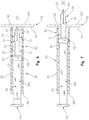
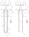
- the tympanostomy tube 30 includes a proximal portion 32, a distal portion 34, and a central portion 36.
- the central portion 36 comprises that portion wherein the distal portion 34 joins the proximal portion 32.
- An axially-extending passageway 40 extends axially through the proximal portion 32. When the tube 30 is in its insertion position, as shown in Fig. 4 , the axially-extending passageway 40 also extends through the distal portion 34.
- the tube 30 also includes a proximal end 42 that is disposed at the proximal end of the proximal portion 32, and a distal end 43 that is disposed at the distal end of the distal portion 34.
- a radially outwardly-extending flange 44 is formed at the proximal end 42 of the ear tube 30.
- the radially outwardly-extending flange includes a proximally-facing end surface 46, and a radially outwardly facing perimetral edge 48.
- An axially distally-facing surface 50 is disposed in an opposed relationship to the proximally-facing end surface 46.
- the radially extending flange 44 is designed to have a diameter larger than the incision made by the tympanostomy tube 30.
- the purpose of this larger diameter is to ensure that the tympanostomy tube 30 remains in its appropriate place on the tympanic membrane after insertion.
- the relatively enlarged diameter flange 44 helps to ensure that the tympanostomy tube is not moved medially out of its engagement with the incision in the tympanic membrane, and through the tympanic membrane into the tympanic cavity.
- the proximal portion 32 includes an axially-extending radially outwardly-facing generally cylindrical surface 52, which extends generally from the proximal end to the distal end of the proximal portion 32.
- the distal portion 34 includes at least two distally disposed legs including a first distal leg 56 and a second distal leg 58.
- the first and second distal legs 56, 58 include, respectively first and second distal ends 60. 62.
- the first and second distal ends 60, 62 are beveled or otherwise configured to have knife like sharp edge surfaces, that comprise cutting surfaces.
- the first and second distal legs 60, 62 should have distal ends 60, 62 that are designed to be sharp enough to easily penetrate the tympanic membrane 98, upon the exertion of an axially and medially directed force on the tympanostomy tube 30, such as an axially-directed force that is applied to the proximally facing surface 46 of the proximal flange 42 in a manner to move the tube 30 medially toward the tympanic cavity.
- the distal ends 60, 62 can be formed with micro-sized teeth or serrations to improve the cutting characteristics of the device and to prevent ripping or rupturing of the ear drum.
- the need for using a knife to make a separate incision is thereby obviated.
- the insertion goes from two steps (i.e. (1) an incision followed by (2) the tube insertion, to one step (i.e. incise and insert, all in one).
- the distal legs 56, 58 are moveable between an insertion position ( Fig. 4 ) and a maintenance position ( Fig. 3 ).
- the insertion position Fig. 4
- the distal legs 56, 58 assume a position wherein they are disposed generally co-axially to the long axis of the passageway 40.
- the cutting edges 60,62 are positioned to cut into a membrane, such as the tympanic membrane, upon an axially, medially exerted force upon the tympanostomy tube 30.
- the distal legs 56, 58 can be moved into a maintenance position as shown in Fig. 3 .
- the long axes of each of the first and second distal legs 56, 58 are disposed at least at an oblique angle to the long axis of the passageway 40.
- the first and second legs 56, 58 are disposed generally co-axially to each other, and along an axis that is generally perpendicular to the long axis of the passageway 40.
- the distal legs 56, 58 each include laterally (exteriorly) facing surfaces 68, 70 and medially (interiorly) facing surfaces 72, 74.
- the designations "medial and lateral" are used to describe these surfaces because, when in the maintenance position and inserted into an ear, the laterally-facing surfaces 68. 70 face laterally, and are disposed against the medially-facing surface of the eardrum 98.
- the medially-facing surfaces 56, 58 face medially inwardly in the middle ear. It will be noted that the medially/lateral designations do not necessarily apply when a device is in the insertion position ( Fig. 4 ) as in the insertion position, the laterally-facing surfaces 68, 70 become radially outwardly-facing surfaces, and the medially-facing surfaces 56, 58 become a radially inwardly-facing surfaces.
- the insertion tool set 80 includes a guide tube member 82, and a plunger or piston 84.
- the insertion tool tube member 82 is generally tube-like in configuration, and preferably has a cylindrical radially outwardly-facing exterior surface 85.
- a generally cylindrical radially inwardly-facing surface 86 defines an axially- extending interior passageway 87 ( Fig. 9 ) which extends between the proximal end 88 and the distal end 90 and is open at both the proximal end 88 and the distal end 90.
- the passageway accommodates the interiorly positioned plunger 84.
- the insertion tool 80 is sized and positioned so that it can be inserted into the external auditory canal, with the proximal end 88 being disposed exteriorly outwardly of the external auditory canal by a sufficient distance so they it can be grabbed and manipulated by the surgeon.
- the distal end 90 when the insertion tube 80 is fully inserted, should be placeable up against, and in contact with the laterally (exteriorly) facing surface 94 of the tympanic membrane 98.
- the tympanic membrane 98 generally includes a laterally (exteriorly) facing surface 94, and a medially (interiorly) facing surface 100.
- the laterally facing surface 94 of the tympanic membrane 98 serves as the interior terminus of the external auditory canal, and the medial surface 100 serves as a wall of the tympanic cavity 102.
- the tympanic membrane 98 stretches across the external auditory canal.
- a plunger member 84 is provided for axially moving the tympanostomy tube 30 in an axially medially direction down the insertion tube 80.
- the plunger 84 may comprise something as simple as a cylindrical rod.
- the rod or plunger 84 may be formed as a plunger-type mechanism that is constructed similarly to a plunger of a syringe.
- the plunger 84 is that it be sized appropriately.
- the plunger should have a flange or head member 110 that has a diameter wider than the interior diameter of the insertion tube 80. This should be done so as to enable the plunger 84 to be inserted only to a certain depth in the insertion tube 80.
- the length of the plunger 84 and the length of the tympanostomy tube 80 should be complementarily sized so that at full insertion of the plunger 84, the tympanostomy tube 30 has been moved axially in a direction and to a point where the tympanostomy tube 30 is appropriately seated within the tympanic membrane 98.
- the plunger 84 includes a cylindrical body portion 108, a proximal end 110 that includes enlarged diameter head 110, and a distal end 112.
- tympanostomy tube 30 and plunger 84 are shown in a position wherein the insertion tube 80 is inserted into the auditory canal, to a point wherein the distal end 90 of the insertion tube 80 rests against the lateral surface 94 of the tympanic membrane 98.
- the tympanostomy tube 30 is shown in its insertion position wherein the distal legs 56, 58 are disposed at a generally co-axially relationship with the axis of the axially-extending passageway 40.
- the plunger has its distal end 112 disposed on and engaged with the upper surface of the radially outwardly extending flange 44 of the tympanostomy tube 200, with the proximal end 110 of the plunger 84 being disposed exteriorly of the insertion tube 80.
- Figs. 6 and 7 do not show the length of the plunger 84 at full scale, due to space limitations. Had these space limitations not existed, the head 110 of the plunger would be shown as extending out further from the proximal end 88 of the insertion tube 80.
- Fig. 7 is a progressive view that shows that the insertion procedure has progressed to the point wherein the plunger 84 has been moved axially medially, to push the tympanostomy tube 30 axially medially.
- This axially medial (distal) movement of the tympanostomy tube 30 has permitted the cutting edge distal ends 60, 62 to pierce and incise the tympanic membrane 98.
- the distal legs 56, 58 are in their insertion position, and the distal ends 60, 62 just barely extend through the tympanic membrane 98, so that only the cutting edges 60, 62 have emerged into the tympanic cavity 102.
- Fig. 8 it will be noted that the plunger 84 is fully extended (to its permissible position) into the interior passageway 87 of the insertion tube 80. such that the distal end 112 of the plunger 84 is adjacent to the distal end 90 of the insertion tube 80. Note also that the distal facing surface of the plunger head 110 rests against the proximal end 88 of insertion tube 80. In this position, the radially outwardly extending flange 44 should rest against, or be close to resting against, the lateral surface 94 of the tympanic membrane 98. Additionally, the proximal portion 32 of the plunger 84 is positioned so that it is generally co-extensive with, and interiorly-disposed within the insertion tube 80.
- the central portion, and the distal portion 34 of the tympanostomy tube 30 are disposed in the tympanic cavity, so that the laterally-facing surfaces 68, 70 ( Fig. 3 ) of the distal legs 56, 58 are disposed adjacent to, and possibly resting against, the medially facing surface 100 of the tympanic membrane 98. It also should be noted that the distal legs 56, 58 have moved from their insertion position to their maintenance position. In the maintenance position, the first and second distal legs 56, 58 are disposed at an oblique angle to the axis of the central passageway 40, and preferably, are disposed generally perpendicularly to the axis of the central passageway 40.
- Fig. 9 is similar generally to Fig. 8 .
- the plunger 84 is removed.
- the insertion tube 80 is also removed, and the final resting place of the tympanostomy tube 30 is shown, with the distal legs 56, 58 being moved into their maintenance position. It will be noted that because of the relatively enlarged radial diameter of the proximal end flange 44, and the relatively enlarged radial diameter of the legs 56. 58, the tympanostomy tube 30 (when in the maintenance position) is prevented from moving axially within the incision in the tympanic membrane 98.
- the flange 44 and the legs 56, 58 thereby help to prevent the tympanostomy tube 30 from being dislodged from the tympanic membrane 98, either by sliding laterally outwardly or medially inwardly.
- the axially extending passageway 40 provides a vent tube between the external auditory canal and the tympanic cavity 102, to help prevent the buildup of fluid therein.
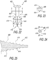
- the first alternate embodiment T type tube 400 is shown in Figs. 22-25 .
- the first alternate embodiment T type tube 400 is constructed generally similarly to the T type tympanostomy tube 30 discussed above in connection with Figs. 3-10 . except for the fact that tube 400 has a serrated distal edge to facilitate the tube 400 incising the tympanic membrane without causing tearing of the membrane. Employing the serrated edges requires certain other modifications of the tube 400 that will be discussed in more detail below.
- the first alternate embodiment T type tube 400 includes an enlarged diameter proximal end 402, and a central portion 404.
- Central portion 404 includes a hollow central passageway 408 that extends generally axially through the central portion 404.
- the distal portion of the tube 400 includes first and second distal legs 408, 410. As illustrated in Figs. 23-25 , the first and second distal legs 408, 410 are not hollow, but rather solid to enhance their structural rigidity, to better adapt them to piercing through the tympanic membrane.
- the first and second distal legs 408, 410 each terminate in a pronged end 412 wherein the radius of the pronged end 412 decreases as one moves distally, so that the end has a shape remeniscent of the end of sa Phillips screwdriver.
- the pronged end 412 includes a pair of generally axially extending serrated fins 414 having radially outwardly facing cutting surfaces.
- the two distal legs 408, 410 are divided along a plane that extends generally from the distal end of the central portion 404, to the distal end of the pronged end 412. This planar cut results in the pronged end 412 being created from the two end portions of the respective first and second distal legs 408, 410.
- FIG. 26-28A A second alternate embodiment T type tympanostomy tube 430 is shown in Figs. 26-28A as also including an enlarged diameter proximal end 432, and a central portion 434. Central portion 434 has a hollow, central passageway 436. It will be noted that a section call out is shown on Fig. 26 that suggests that the user view Fig. 5 , for the section view taken along Figs. 5-5 . This use of Fig. 5 to illustrate tympanostomy tube 430 indicates that tympanostomy tube 430 is generally identical in this view with tympanostomy tube 30.
- First 440 and second 442 distal legs are coupled to the distal portion of the central portion 434.
- the distal legs 440, 442 extend generally axially when the tympanostomy tube 430 is in its insertion portion, and are movable to extend to about a 90 degree angle when the tympanostomy tube 430 is in its inserted maintenance position.
- the first distal leg 440 does not terminate at the distal end of the tympanostomy tube 430. Rather, the first distal leg 440 has a truncated, blunt cut end 441, that terminates the first distal leg 440 at a position just proximal of the four-pronged distal end 444 of the tympanostomy tube 430.
- This truncated blunt end 441 results in the four pronged tapered distal end 444 being formed of a single, unitary member, as it illustrated in Fig. 28 and has a shape similar to a Phillips screwdriver with four prongs.
- the pronged tapered distal end 440 is formed wholly out of the second distal leg 442.
- the unbroken, tapered pronged distal end 444 is believed by the Applicant to enable the use of a greater number of serrated fins 446, due to the absence of a cut line.
- the serrated fins 446 extend generally axially along the tapered outer surface of the tapered, four pronged distal end 444, and have serrations that extend radially outwardly to form a radially outward extending cutting surface. As with the first alternate embodiment, the plurality of serrated fins 446 promote the cutting of the tympanic membrane by the distal conical end 444 as it incises the tympanic membrane, and reduces the likelihood of tearing of the tympanic membrane.
- a third alternate embodiment T type tympanostomy tube 460 is shown in Figs. 29-32 .
- the embodiment shown in Figs. 29-32 includes an enlarged diameter proximal end 462 and a central portion 464.
- the central portion 464 includes an axially extending, central passageway 466 that extends all the way from the opening at the proximal end 462 of the tube 460. to the distal end of the tube 460.
- the third alternate embodiment 460 does not include a solid distal end.
- First and second distal legs 468, 480 extend distally from the generally distal end of the central portion 464.
- the first distal leg 468 and second distal leg 480 terminate at the distal cutting portions 470, 482 of the respective first and second distal legs 468, 480.
- the distal cutting portion 470 of the first distal leg has a generally inverted conical shape, that includes a hemi-cylindrical outer surface 477 and an angled serrated inner surface 478.
- the distal end 482 also includes a generally hemi-cylindrical outer surface 484 and angled, serrated inner portion 486. ⁇ s with the first and second alternate embodiments, the serrated inner surfaces 478, 486 help to better cut through the meadis of the tympanic membrane, to help reduce tearing of the tympanic membrane.
- a fourth embodiment T-type tube is shown.
- T-tube 500 shown in Fig. 33 includes a proximal flange portion 502, a relatively reduced diameter tubular central portion 504 that includes an axially extending central passageway 506.
- the fourth embodiment T-tube 500 also includes a first leg portion and a second leg portion that are moveable between an insertion position as shown in Fig. 33 and a maintenance position wherein the legs extend along a line generally perpendicular to the long axis of the central passageway 506.
- a cutting tip portion 512 is coupled to the second leg 510.
- the cutting tip portion 512 can be coupled in either a removable coupling or a fixed coupling manner.
- the cutting tip portion 512 includes serrated edges.
- the cutting tip portion 512 is made from a dissolvable or absorbable material.
- absorbable material is a material that the body will naturally degrade and absorb over time.
- absorbable suture materials include materials such as cat gut, as well as synthetic materials such as polyglycolic acid, polylactic acid, polydioxanone and caprolactone. These absorbable materials are broken down by various processes including hydrolysis, proteolytic enzymatic degradation and others.
- an absorbable cutting tip The purpose of employing an absorbable cutting tip is that over time, the cutting tip will become absorbed, and no longer be present within the inner ear to cause any cuts, abrasions and the like.
- a tympanostomy tube 516 with an absorbable cutting surface is shown in Fig. 34 .
- the tube 516 of Fig. 34 is not a T-type tube tympanostomy tube, but rather is more of a standard grommet-shaped tympanostomy tube 516.
- Tympanostomy tube 516 includes a proximal flange 518 and a reduced diameter tubular central portion 520 that includes a central passageway 522 having an axis.
- a distal flange 524 has a relatively enlarged diameter when compared to the relatively reduced central portion 520 and is disposed at the distal end of the tympanostomy tube 516.
- An absorbable serraied edge cutting tip 526 includes a proximal portion 528 that is shaft-like, and is insertable into the central passageway 522 for coupling the distal cutting member 526 to the tympanostomy tube 516.
- the cutting edge 530 is generally tapered in shape, and includes serrated edge cutting surfaces for better cutting through the tympanic membrane, in a manner that does not tear the tympanic membrane.
- the cutting heads 512, 530 of the tubes 500, 516 shown in Figs. 33 and 34 are shown as being conical in configuration, they can be shaped similar to a Phillips screwdriver, so that their cross-sectional shape would appear generally similar to that shown in Figs. 27 and 28 .
- the first, second and third alternate embodiments operate generally similarly to the manner discussed above in connection with the first embodiment 30 of the T shaped tympanic tube.
- a grommet tympanostomy tube 200 according to an embodiment of the invention is shown in Figs. 11-20 .
- the tympanostomy tube 200 includes an enlarged diameter proximal end 202, an enlarged diameter distal end 204, and a reduced diameter central portion 206.
- the central portion 206 is preferably generally cylindrical in configuration and is tubular in nature.
- the cylindrical reduced diameter central portion 206 includes a generally cylindrical outer wall 210 and a generally cylindrical inner wall 216.
- Cylindrical inner wall 216 defines an axially-extending passageway 218 that has a proximal opening 220 adjacent the proximal end 202 of the tube 200, and a distal opening 222 disposed adjacent to the distal end 204.
- the axially-extending passageway 218 defines a long axis of the tympanostomy tube 200.
- the proximal and distal openings 220, 222 and passageway 18 all open so that air can flow between the outer ear, and in particular, the external auditory canal, and the middle ear, and in particular, the tympanic cavity 102. This flow of air helps to reduce the buildup of liquid mucus and fluid in the inner ear (tympanic cavity), and thus helps to combat infections and resultant ear aches.
- the proximal portion 202 includes a radially-extending flange 226 that includes a proximally-facing radially-extending surface 228, and an opposed, distally-facing radially-extending surface 230 ( Figs. 11 , 14 ).
- the enlarged diameter radially-extending flange 226 performs a function similar to a nail head, as it helps to prevent the tympanostomy tube 200 from moving medially through the incision in which the tympanostomy tube 200 is placed.
- the radially-extending flange 226 also includes a radially outwardly-facing edge surface 232. Although the edge surface 232 is shown as being squared off, it can be a rounded-end surface 232 in the final device.
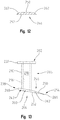
- the distal portion 204 of the tympanostomy tube 202 includes an eccentric distal flange 238, that is generally ovaloid shaped in configuration.
- the eccentric distal flange 238 is placed in an eccentric relation relative to the axially-extending passageway 218, and central portion 206, so that the distal flange 238 includes a relatively shorter rear portion 242, and a relatively elongated forward incising portion 246 that includes an incising edge 262 of the tympanostomy tube 202 that cuts through the tympanic membrane 98, to form an incision in the tympanic membrane 98.
- the cutting (incising) edge 262 extends to the widest part of the ovoid distal forward incising portion 246 ( Fig. 11 , 13A and 15 ).
- the tympanostomy tube 200 will simultaneously cut through and be passed through the incision to insert the tympanostomy tube 200 into the tympanic membrane 98 in one step.
- the tympanostomy tube's eccentric distal flange 238 is also placed at an oblique angle to the axis of the axially-extending passageway 218.
- the eccentric distal flange 238 disposed at an angle up between about 110° and 150° relative to the long axis of the tympanostomy tube 200. This angled placement of the distal flange 238 helps to better position the tympanostomy tube 200 cutting edge 262 visually and economically for incising and cutting through the tympanic membrane 98.
- the eccentric distal flange 238 includes an upper proximally-facing surface 250, and a lower distally-facing surface 252.
- the distal flange 238 includes a perimetrat surface 260 that includes a forward portion 246 having a cutting edge 262, and a non-cutting edge rearward portion 268.
- the thickness of a distal flange 238 varies in different areas of the flange 238.
- the flange 238 is designed to be generally thinner in the forward portion 246, adjacent to the knife-shaped leading edge 266, and more relatively blunted and thicker at the trailing edge 268 of the smaller rear portion 242.
- the flange 238 is knife edge like, such that the distal flange 238 is thickest at the rearward edge 268, and is beveled, such that the thickness decreases as one moves forward to the forward portion 242, with the flange 238 being at its thinnest at forward leading edge 266.
- the eccentric flange 238 should be made from material than can be designed to be sufficiently rigid, and sharp at the leading edge 266. and along the entire cutting edge 262 so as to be able to cut through the tympanic membrane 98.
- This toughness and sharpness can be achieved with either a plastic, composite or a metal distal edge flange 238.
- the cutting edge 262 may extend along the flange 238 edge 260 from the leading edge 266 to the widest point 259 ( Fig. 15 ) of the flange 238 to ensure better cutting characteristics.
- the edge 262 can be formed with micro-sized teeth or serrations to improve the cutting characteristics of the device and prevent ripping or rupturing the eardrum by puncture.
- the leading edge 266 should be rounded, rather then pointed, so that the leading edge 266 performs a controlled cut rather than a pressure puncture, rupture or shred through the tympanic membrane 98.
- Fig. 17 the tube 200 is shown as being inserted in an ear canal (not shown).
- the proximal end 202 of the tube is gripped by forceps for so that the surgeon can manipulate the tympanostomy tube 200 into its appropriate position within the ear canal so that the distal flange 238 is placed adjacent to the lateral surface of the tympanic membrane 98.
- a thin forceps such as an alligator type.
- Miltex micro ear forceps is employed wherein the first and second blades of the forceps are thin enough to enable the first blade to be inserted into passageway 218 to grip inner cylindrical surface 216, while the second blade is disposed exteriorly of the central portion to grip the exterior cylindrical surface 210.
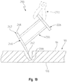
- the surgeon can easily position the tube so that the long axis 218 of the tube 200 is disposed at an oblique angle, and preferably almost generally perpendicular to the plane of the laterally facing surface of the ear drum 98.
- the cutting distal edge incising portion 266 is placed adjacent to the laterally-facing outer surface 94 of the tympanic membrane 98.
- the axis of the tube 200 (and its axially extending passageway) is held at an angle from perpendicular to the plane of the lateral surface of membrane 98, such that the axis of the axially-extending passageway 218 is disposed at an angle to the tympanic membrane 98 of approximately 45 degrees.
- the forceps 273 are then manipulated by the surgeon to be moved in an axial, medial direction with micro-back-and-forth, knife-like cutting movements, toward the laterally outwardly facing surface 94 of the tympanic membrane 98, so that the leading edge 266 can cut into and cut through laterally outwardly-facing surface 94 the tympanic membrane 98.
- the remainder of the trailing cutting edge 262 follows and cuts its way through the incised opening of tympanic membrane 98.
- the leading edge 266 of the incising edge 262 of the tube is designed to not "pierce” or “puncture” the tympanic membrane 87 since piercing or puncturing an ear drum 98 can lead to a fracture, shred or rupture of the eardrum 98.
- Eardrum damage that has occurred in prior art designs has caused the current preferred approach to comprise the "two-step” approach of using a knife to incise an opening into the eardrum followed by a secondary step of placing the tube in portion.
- the leading edge 266 generally provides the primary knife-like cutting surface, through the membrane 98. However, the entire cutting surface 262 also serves to cut the tympanic membrane in those areas of the tympanic membrane that are engaged by other areas of the cutting surface 262, as shown in Fig. 18 .
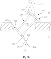
- Fig. 19 the next progression shows that the forceps 273 have moved the tympanostomy tube 200 axially forwardly (and medially) to a point wherein the leading edge 266 has emerged into the tympanic cavity, TC where as the proximal edge 202 still resides in the external auditory canal, AC.
- the shown width of the incision is not indicative of a high volume of tympanic material being cut away.
- leading edge 266 will make a slit-like incision in the tympanic membrane 98 tissue, with the tissue being cut wide enough radially outwardly to allow the flange 238 to pass through the membrane 98, and then, to permit the tissue of the tympanic membrane 98 to engage the outer cylindrical surface 210 of the central portion 206 of the tympanostomy tube 200.
- the incision heals, it will snugly engage the cylindrical surface 210 to help hold the tympanostomy tube 206 in its place in the tympanic membrane 98.
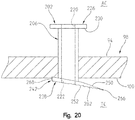
- tympanostomy tube 200 is shown in its final position. It will be noted that the proximal portion 202 of the tympanostomy tube 200 is disposed within the external auditory canal.
- the proximal (first) flange 226, and in particular, the distal, medially-facing surface 230 of the proximal flange 226 rests against the lateral, outwardly-facing surface 94 of the tympanic membrane 98.
- the diameter of the first flange 226 is generally greater than the diameter of the incision cut through the tympanic membrane 98. the width and diameter of the flange 226 will help to prevent the tympanostomy tube 200 from migrating in a medial direction into the tympanic cavity.
- the distal flange 238 is inserted into the tympanic cavity 102. As the diameter of the distal second flange 238 is greater than the diameter of the incision, the distal flange 238 will help to prevent the tympanostomy tube 200 from migrating in a lateral direction out of the tympanic cavity TC, and into the external auditory canal AC.
- the proximal facing surface 250 engages and is placed against the medially-facing surface 100 of the tympanic membrane 98. Due to the oblique angle of the eccentric flange 238, the foreshortened rear portion 242 will more tightly and closely engage the medial surface 100 of the eardrum 98, than the more distally disposed forward leading edge portion 246.
Landscapes
- Health & Medical Sciences (AREA)
- Life Sciences & Earth Sciences (AREA)
- Biomedical Technology (AREA)
- Acoustics & Sound (AREA)
- Biophysics (AREA)
- Otolaryngology (AREA)
- Psychology (AREA)
- Engineering & Computer Science (AREA)
- Physics & Mathematics (AREA)
- Heart & Thoracic Surgery (AREA)
- Vascular Medicine (AREA)
- Animal Behavior & Ethology (AREA)
- General Health & Medical Sciences (AREA)
- Public Health (AREA)
- Veterinary Medicine (AREA)
- Surgery (AREA)
- Prostheses (AREA)
Claims (8)
- Ein Paukenröhrchen (200) zum Einführen und Verbleib in einem Trommelfell eines Mittelohrs, wobei das Paukenröhrchen (200) aus- einem Körper besteht, der ein erstes Endteil (202), ein zweites Endteil (204), ein Mittelteil (206), das zwischen dem ersten (202) und dem zweiten Endteil (204) angeordnet ist, und einen sich axial erstreckenden Durchgang (218) mit einem ersten offenen Ende (220), das angrenzend an das erste Endteil (202) angeordnet ist, und ein zweites offenes Ende (222), das angrenzend an das zweite Endteil (204) angeordnet ist, und eine Achse, die sich zwischen dem ersten offenen Ende und dem zweiten offenen Ende erstreckt, beinhaltet;dem ersten Endteil (202) besteht, das eine sich allgemein radial erstreckende Kante (226) mit einem relativ vergrößertem Durchmesser beinhaltet;einem Mittelteil (206) besteht, das einen verminderten Durchmesserteil beinhaltet, der so bemessen ist, dass er sich durch das Gewebe des Trommelfells erstreckt und darin verbleibt;dem zweiten Endteil (204) besteht, das eine zweite Kante (238) mit einem relativ vergrößerten Durchmesser beinhaltet, die angrenzend an das zweite Endteil (204) angeordnet ist, wobei die zweite Kante (238) einen perimetrischen Rand (260) mit einem Schneideteil (262) beinhaltet, das ausreichend scharf ist, um während des Einführens des Paukenröhrchens (200) durch das Trommelfell das Trommelfell zu durchschneidendadurch gekennzeichnet, dass das Schneideteil (262) eine abgerundete Vorderkante (262) aufweist, wobei die abgerundete Vorderkante (262) eine gezackte Kante (262) zum Schneiden durch des Trommelfells ist.
- Das Paukenröhrchen gemäß Anspruch 1, wobei die zweite sich radial erstreckende Kante (238) ein relativ größeres Vorderteil (246) beinhaltet, das die abgerundete Vorderkante (262) und einen relativ kleineren hinteren Teil (242) aufweist.
- Das Paukenröhrchen gemäß Anspruch 2, wobei die zweite Kante (238) eine verjüngte Dicke aufweist, so dass das hintere Teil (242) allgemein dicker als das Vorderteil (246) ist.
- Das Paukenröhrchen gemäß der Ansprüche 1, 2 oder 3, wobei die zweite Kante (238) in einer Ebene angeordnet ist, die in einem schiefen Winkel zur Achse des sich axial erstreckenden Durchgangs angeordnet ist.
- Das Paukenröhrchen gemäß Anspruch 4, wobei die zweite Kante (238) in einem schiefen Winkel angeordnet ist, so dass -wenn das Paukenröhrchen (200) gegen eine außenliegende Fläche eines Trommelfells angesetzt ist, so dass die außenliegende Fläche in einer Ebene angeordnet ist, die sich allgemein senkrecht zur Achse des sich axial erstreckenden Durchgangs befindet- das Vorderteil (246) in einer Ebene in einem Schnittwinkel von weniger als ungefähr 90 Grad relativ zur außenliegenden Fläche des Trommelfells angeordnet ist.
- Das Paukenröhrchen gemäß Anspruch 5, wobei der Schnittwinkel des Vorderteils (246) zwischen ungefähr 30 Grad und 70 Grad liegt, wenn die Achse des sich axial erstreckenden Durchgangs (218) im allgemeinen senkrecht zu einer außenliegenden Fläche eines Trommelfells gehalten wird.
- Das Paukenröhrchen gemäß Anspruch 1, wobei die zweite sich radial erstreckende Kante (238) einen relativ größeren Vorderteil (246) beinhaltet, der eine abgerundete Vorderkante (262), einen relativ kleineren hinteren Teil (242) aufweist, und wobei die zweite Kante (238) eine verjüngte Dicke aufweist, so dass der hintere Teil (242) allgemein dicker als der Schneideteil (262) der Vorderkante (246) ist.
- Das Paukenröhrchen gemäß Anspruch 1, wobei die zweite Kante (238) in einem schiefen Winkel zur Achse des sich axial erstreckenden Durchgangs (218) angeordnet ist, so dass -wenn das Paukenröhrchen (200) gegen eine außenliegende Fläche eines Trommelfells angesetzt wird, so dass die außenliegende Fläche in einer Ebene angeordnet wird, die sich allgemein senkrecht zur Achse des sich axial erstreckenden Durchgangs (218) befindet- die gezackte Kante (262) in einem Schnittwinkel von weniger als ungefähr 90 Grad relativ zur außenliegenden Fläche des Trommelfells angeordnet ist.
Priority Applications (2)
| Application Number | Priority Date | Filing Date | Title |
|---|---|---|---|
| PL13875015T PL2956098T4 (pl) | 2013-02-12 | 2013-07-17 | Jednoetapowa rurka tympanostomijna |
| EP19203097.1A EP3620140B1 (de) | 2013-02-12 | 2013-07-17 | Einstufige tympanostomiekanüle |
Applications Claiming Priority (2)
| Application Number | Priority Date | Filing Date | Title |
|---|---|---|---|
| US13/764,875 US9907699B2 (en) | 2012-07-05 | 2013-02-12 | One step tympanostomy tube and method of inserting same |
| PCT/US2013/050931 WO2014126609A1 (en) | 2013-02-12 | 2013-07-17 | One step tympanostomy tube and insertion method |
Related Child Applications (1)
| Application Number | Title | Priority Date | Filing Date |
|---|---|---|---|
| EP19203097.1A Division EP3620140B1 (de) | 2013-02-12 | 2013-07-17 | Einstufige tympanostomiekanüle |
Publications (3)
| Publication Number | Publication Date |
|---|---|
| EP2956098A1 EP2956098A1 (de) | 2015-12-23 |
| EP2956098A4 EP2956098A4 (de) | 2016-11-16 |
| EP2956098B1 true EP2956098B1 (de) | 2019-10-23 |
Family
ID=49879092
Family Applications (2)
| Application Number | Title | Priority Date | Filing Date |
|---|---|---|---|
| EP19203097.1A Active EP3620140B1 (de) | 2013-02-12 | 2013-07-17 | Einstufige tympanostomiekanüle |
| EP13875015.3A Active EP2956098B1 (de) | 2013-02-12 | 2013-07-17 | Einstufige tympanotomieröhre |
Family Applications Before (1)
| Application Number | Title | Priority Date | Filing Date |
|---|---|---|---|
| EP19203097.1A Active EP3620140B1 (de) | 2013-02-12 | 2013-07-17 | Einstufige tympanostomiekanüle |
Country Status (7)
| Country | Link |
|---|---|
| US (2) | US9907699B2 (de) |
| EP (2) | EP3620140B1 (de) |
| JP (1) | JP6141457B2 (de) |
| CA (1) | CA2900823C (de) |
| ES (2) | ES2768424T3 (de) |
| PL (2) | PL3620140T3 (de) |
| WO (1) | WO2014126609A1 (de) |
Families Citing this family (20)
| Publication number | Priority date | Publication date | Assignee | Title |
|---|---|---|---|---|
| US10365835B2 (en) * | 2014-05-28 | 2019-07-30 | Micron Technology, Inc. | Apparatuses and methods for performing write count threshold wear leveling operations |
| CA2980504C (en) | 2015-03-20 | 2024-01-30 | Massachusetts Eye And Ear Infirmary | Artificial tympanic membrane devices and uses |
| US10484802B2 (en) | 2015-09-17 | 2019-11-19 | Domestic Legacy Limited Partnership | Hearing aid for people having asymmetric hearing loss |
| DE102016209871A1 (de) * | 2016-06-06 | 2017-12-07 | Robert Bosch Gmbh | Stanzvorrichtung und Verfahren zum Stanzen eines Lumens und Implantieren einer Implantateinrichtung |
| US10799341B2 (en) | 2016-09-16 | 2020-10-13 | Massachusetts Eye And Ear Infirmary | Ear canal grafts |
| KR200488434Y1 (ko) * | 2017-06-01 | 2019-01-30 | 임동혁 | 중이염 환기관 |
| EP3681450B1 (de) * | 2017-09-13 | 2024-09-04 | National University of Singapore | Vorrichtung für einschnitt und insertion eines beatmungsschlauches |
| DE102018201030B4 (de) | 2018-01-24 | 2025-10-16 | Kardion Gmbh | Magnetkuppelelement mit magnetischer Lagerungsfunktion |
| DE102018206725A1 (de) | 2018-05-02 | 2019-11-07 | Kardion Gmbh | Empfangseinheit, Sendeeinheit, Energieübertragungssystem und Verfahren zur drahtlosen Energieübertragung |
| DE102018206754A1 (de) | 2018-05-02 | 2019-11-07 | Kardion Gmbh | Verfahren und Vorrichtung zur Bestimmung der Temperatur an einer Oberfläche sowie Verwendung des Verfahrens |
| DE102018206724A1 (de) | 2018-05-02 | 2019-11-07 | Kardion Gmbh | Energieübertragungssystem und Verfahren zur drahtlosen Energieübertragung |
| DE102018206727A1 (de) | 2018-05-02 | 2019-11-07 | Kardion Gmbh | Energieübertragungssystem und Empfangseinheit zur drahtlosen transkutanen Energieübertragung |
| DE102018206731A1 (de) | 2018-05-02 | 2019-11-07 | Kardion Gmbh | Vorrichtung zur induktiven Energieübertragung in einen menschlichen Körper und Verwendung der Vorrichtung |
| DE102018206750A1 (de) | 2018-05-02 | 2019-11-07 | Kardion Gmbh | Vorrichtung zur induktiven Energieübertragung in einen menschlichen Körper und deren Verwendung |
| DE102018208555A1 (de) | 2018-05-30 | 2019-12-05 | Kardion Gmbh | Vorrichtung zum Verankern eines Herzunterstützungssystems in einem Blutgefäß, Verfahren zum Betreiben und Herstellverfahren zum Herstellen einer Vorrichtung und Herzunterstützungssystem |
| US12569334B2 (en) | 2019-05-02 | 2026-03-10 | Massachusetts Eye And Ear Infirmary | Winged grafts for tympanic membrane repair and augmentation |
| US11116668B1 (en) | 2020-05-04 | 2021-09-14 | Roger D. Haring | Cross-flange tympanostomy tube |
| CN114081720B (zh) * | 2020-08-06 | 2025-01-24 | 合肥启灏医疗科技有限公司 | 耳部手术装置 |
| US11699551B2 (en) | 2020-11-05 | 2023-07-11 | Kardion Gmbh | Device for inductive energy transmission in a human body and use of the device |
| CN120114253B (zh) * | 2025-03-21 | 2026-04-03 | 柏为(武汉)医疗科技股份有限公司 | 鼓膜通气管置入装置 |
Family Cites Families (45)
| Publication number | Priority date | Publication date | Assignee | Title |
|---|---|---|---|---|
| US2670738A (en) | 1952-03-14 | 1954-03-02 | Gibbons Thomas | Ear protector |
| US3636943A (en) * | 1967-10-27 | 1972-01-25 | Ultrasonic Systems | Ultrasonic cauterization |
| US3897786A (en) | 1971-02-05 | 1975-08-05 | Richards Mfg Co | Disposable myringotomy apparatus |
| US3807409A (en) | 1972-08-31 | 1974-04-30 | Medical Prod Corp | Medical ventilation tube |
| US4695275A (en) | 1983-12-16 | 1987-09-22 | Donald Bruce | Middle ear ventilation tube |
| US4650488A (en) * | 1984-05-16 | 1987-03-17 | Richards Medical Company | Biodegradable prosthetic device |
| US5443493A (en) | 1989-09-22 | 1995-08-22 | Alfred E. Mann Foundation For Scientific Research | Cochlea stimulating electrode assembly, insertion tool, holder and method of implantation |
| US5053040A (en) | 1989-11-09 | 1991-10-01 | Goldsmith Iii Manning M | Method of performing a myringotomy |
| US5047053A (en) | 1990-02-27 | 1991-09-10 | Smith & Nephew Richards Inc. | Permanent middle ear vent tube and method of insertion |
| US5137523A (en) | 1991-06-10 | 1992-08-11 | Peerless Sidney A | Otological drain tube |
| NL9101898A (nl) | 1991-11-14 | 1993-06-01 | Marinus Johannes Hageman | Trommelvliesbuisje. |
| US5317938A (en) * | 1992-01-16 | 1994-06-07 | Duke University | Method for making microstructural surgical instruments |
| US5207685A (en) * | 1992-02-11 | 1993-05-04 | Cinberg James Z | Tympanic ventilation tube and related technique |
| US5254120A (en) | 1992-02-11 | 1993-10-19 | Cinberg James Z | Myringotomy ventilliation tube, method, applicator and kit |
| US5178623A (en) | 1992-02-11 | 1993-01-12 | Cinberg James Z | Tympanic ventilation tube, applicator, and related technique |
| US5466239A (en) * | 1992-07-28 | 1995-11-14 | Cinberg; James Z. | Myringotomy ventilation tube and associated method |
| US5489286A (en) | 1992-07-28 | 1996-02-06 | Cinberg; James Z. | Antibiotic impregnated myringotomy ventilation tube |
| US6361526B1 (en) | 1993-11-01 | 2002-03-26 | Medtronic Xomed, Inc. | Antimicrobial tympanostomy tube |
| US6406453B1 (en) | 1995-04-26 | 2002-06-18 | Medtronic Xomed, Inc. | Composite ventilation tube |
| US5643280A (en) | 1995-12-07 | 1997-07-01 | The Anspach Effort, Inc. | Integral myringotomy tube and inserter |
| US5645584A (en) | 1996-02-21 | 1997-07-08 | Suyama Dental Laboratory Inc. | Tympanostomy tube and method for producing the same |
| US5775336A (en) | 1996-05-31 | 1998-07-07 | Georgetown University | Tubular medical device |
| US6379323B1 (en) * | 1997-05-09 | 2002-04-30 | Acoustic Technologies, Inc. | Bio erodable myringotomy tube |
| US6045528A (en) | 1997-06-13 | 2000-04-04 | Intraear, Inc. | Inner ear fluid transfer and diagnostic system |
| US6042574A (en) | 1998-03-11 | 2000-03-28 | O'halloran; Gerard | Oval ventilation ear tube |
| US8480610B1 (en) | 1998-12-08 | 2013-07-09 | Frank C. Hill | Ear tube and method of insertion |
| US6120484A (en) | 1999-02-17 | 2000-09-19 | Silverstein; Herbert | Otological implant for delivery of medicament and method of using same |
| US6245077B1 (en) | 2000-01-21 | 2001-06-12 | Exmoor Plastics Ltd. | Universal myringotomy tube/aural grommet inserter and methods |
| US6770080B2 (en) | 2001-04-26 | 2004-08-03 | Fenestra Medical, Inc. | Mechanically registered videoscopic myringotomy/tympanostomy tube placement system |
| US7097661B2 (en) * | 2001-08-03 | 2006-08-29 | Perry Microtube Pty Ltd | Ventilation tube for a middle ear |
| US20030033016A1 (en) | 2001-08-07 | 2003-02-13 | Gyrus Group Plc | Implant sheath |
| US6648873B2 (en) | 2001-09-21 | 2003-11-18 | Durect Corp. | Aural catheter system including anchor balloon and balloon inflation device |
| JP2004235983A (ja) * | 2003-01-30 | 2004-08-19 | Yuichi Sasaki | 綿球挿入治具 |
| EP1773219A2 (de) | 2004-06-24 | 2007-04-18 | BCU International | Verfahren und medizinprodukt für den schnellen und genauen eingang durch weiches gewebe und knochen |
| CA2600396C (en) | 2005-03-22 | 2014-09-02 | S. George Lesinski | Implanting a therapeutic appliance into the cochlea |
| US8197433B2 (en) | 2005-06-20 | 2012-06-12 | Otomedics Advanced Technologies, Ltd. | Ear tubes |
| JP4238905B2 (ja) | 2006-09-05 | 2009-03-18 | 久郎 藤原 | 鼓膜ドレーンチューブ |
| JP5021285B2 (ja) * | 2006-12-18 | 2012-09-05 | 裕生 梅田 | 中空針及びチューブ留置用器具 |
| CN102014795B (zh) | 2008-02-20 | 2015-02-25 | 普利塞普提斯医药有限公司 | 通风装置和用于该通风装置的插入系统 |
| US20090299379A1 (en) | 2008-05-28 | 2009-12-03 | Yeshayahu Katz | Myringotomy instrument |
| EP2337607B1 (de) | 2008-10-15 | 2018-06-13 | Med-El Elektromedizinische Geräte GmbH | Vorrichtung zur abgabe von arzneimitteln an das innenohr |
| DE102009006047B3 (de) | 2009-01-24 | 2010-03-25 | Heinz Kurz Gmbh Medizintechnik | Passive Gehörknöchelchenprothese mit Applikator |
| EP3656317A1 (de) | 2011-09-02 | 2020-05-27 | Stryker Corporation | Chirurgisches system mit einem instrument und verfahren zur verwendung des instruments |
| US8529495B1 (en) | 2012-10-02 | 2013-09-10 | Hasan M. Sh. Sh. Alshemari | Middle ear ventilation tube |
| US8480611B1 (en) | 2012-10-02 | 2013-07-09 | Hasan M. Sh. Sh. Alshemari | Middle ear ventilation tube |
-
2013
- 2013-02-12 US US13/764,875 patent/US9907699B2/en active Active
- 2013-07-17 PL PL19203097.1T patent/PL3620140T3/pl unknown
- 2013-07-17 WO PCT/US2013/050931 patent/WO2014126609A1/en not_active Ceased
- 2013-07-17 EP EP19203097.1A patent/EP3620140B1/de active Active
- 2013-07-17 PL PL13875015T patent/PL2956098T4/pl unknown
- 2013-07-17 JP JP2015556926A patent/JP6141457B2/ja active Active
- 2013-07-17 ES ES13875015T patent/ES2768424T3/es active Active
- 2013-07-17 ES ES19203097T patent/ES2926786T3/es active Active
- 2013-07-17 EP EP13875015.3A patent/EP2956098B1/de active Active
- 2013-07-17 CA CA2900823A patent/CA2900823C/en active Active
-
2016
- 2016-05-23 US US15/161,379 patent/US9987168B2/en active Active
Non-Patent Citations (1)
| Title |
|---|
| None * |
Also Published As
| Publication number | Publication date |
|---|---|
| JP2016511664A (ja) | 2016-04-21 |
| CA2900823C (en) | 2018-10-16 |
| US20160262937A1 (en) | 2016-09-15 |
| US9907699B2 (en) | 2018-03-06 |
| EP3620140B1 (de) | 2022-06-22 |
| EP3620140A1 (de) | 2020-03-11 |
| CA2900823A1 (en) | 2014-08-21 |
| PL2956098T3 (pl) | 2020-06-15 |
| JP6141457B2 (ja) | 2017-06-07 |
| EP2956098A4 (de) | 2016-11-16 |
| ES2926786T3 (es) | 2022-10-28 |
| ES2768424T3 (es) | 2020-06-22 |
| US9987168B2 (en) | 2018-06-05 |
| PL2956098T4 (pl) | 2020-06-15 |
| EP2956098A1 (de) | 2015-12-23 |
| PL3620140T3 (pl) | 2022-10-24 |
| WO2014126609A1 (en) | 2014-08-21 |
| US20140012282A1 (en) | 2014-01-09 |
Similar Documents
| Publication | Publication Date | Title |
|---|---|---|
| EP2956098B1 (de) | Einstufige tympanotomieröhre | |
| US7540875B2 (en) | Surgical cutting tool with automatically retractable blade assembly | |
| US6835201B2 (en) | Trocar | |
| EP1453426B1 (de) | Trokar mit verbessertem durchstechdorn | |
| US5178623A (en) | Tympanic ventilation tube, applicator, and related technique | |
| JP2008142533A (ja) | トロカール | |
| US20030009185A1 (en) | Method and apparatus for placing and maintaining a percutaneous tube into a body cavity | |
| US9855073B2 (en) | Circumcision stapler | |
| WO2008027829A3 (en) | Tissue extraction device and method of using the same | |
| EP3251607A1 (de) | Achillessehnennähinstrument und verwendungsverfahren dafür | |
| US10687982B2 (en) | One-step tympanostomy tube and method for inserting same | |
| US20240307231A1 (en) | Tympanostomy tube insertion device | |
| US20140276597A1 (en) | Nasal ventilation system and method of using same | |
| US20060178677A1 (en) | Hair punch | |
| WO2011047857A1 (en) | Circular hemostatic apparatus and method of use thereof | |
| CN206355099U (zh) | 一种髂骨微创取骨器 | |
| US20160158501A1 (en) | Percutaneous scalpel and tissue dilator | |
| CN104188696B (zh) | 腕管综合征微创手术器械 | |
| CN218922654U (zh) | 一种旋切针的钻石形棱形反刀刃针头结构 | |
| DE102010032151B4 (de) | Medizinisches Handinstrument zum Einbringen einer Inzision in die Sklera des Auges und Trokarsystem | |
| CN208551948U (zh) | 一款用于脊柱内镜手术的深筋膜放射状切开器 | |
| CN204147089U (zh) | 一种在鼻腔泪囊吻合术中泪囊及鼻粘膜切开刀 | |
| CN204337012U (zh) | 拆除器 | |
| CN110840516A (zh) | 开孔刀头和应用其的孔道开路器 |
Legal Events
| Date | Code | Title | Description |
|---|---|---|---|
| PUAI | Public reference made under article 153(3) epc to a published international application that has entered the european phase |
Free format text: ORIGINAL CODE: 0009012 |
|
| 17P | Request for examination filed |
Effective date: 20150811 |
|
| AK | Designated contracting states |
Kind code of ref document: A1 Designated state(s): AL AT BE BG CH CY CZ DE DK EE ES FI FR GB GR HR HU IE IS IT LI LT LU LV MC MK MT NL NO PL PT RO RS SE SI SK SM TR |
|
| AX | Request for extension of the european patent |
Extension state: BA ME |
|
| DAX | Request for extension of the european patent (deleted) | ||
| A4 | Supplementary search report drawn up and despatched |
Effective date: 20161014 |
|
| RIC1 | Information provided on ipc code assigned before grant |
Ipc: A61F 11/00 20060101AFI20161010BHEP |
|
| GRAP | Despatch of communication of intention to grant a patent |
Free format text: ORIGINAL CODE: EPIDOSNIGR1 |
|
| STAA | Information on the status of an ep patent application or granted ep patent |
Free format text: STATUS: GRANT OF PATENT IS INTENDED |
|
| INTG | Intention to grant announced |
Effective date: 20190517 |
|
| GRAS | Grant fee paid |
Free format text: ORIGINAL CODE: EPIDOSNIGR3 |
|
| GRAA | (expected) grant |
Free format text: ORIGINAL CODE: 0009210 |
|
| STAA | Information on the status of an ep patent application or granted ep patent |
Free format text: STATUS: THE PATENT HAS BEEN GRANTED |
|
| AK | Designated contracting states |
Kind code of ref document: B1 Designated state(s): AL AT BE BG CH CY CZ DE DK EE ES FI FR GB GR HR HU IE IS IT LI LT LU LV MC MK MT NL NO PL PT RO RS SE SI SK SM TR |
|
| REG | Reference to a national code |
Ref country code: GB Ref legal event code: FG4D |
|
| REG | Reference to a national code |
Ref country code: CH Ref legal event code: EP |
|
| REG | Reference to a national code |
Ref country code: IE Ref legal event code: FG4D |
|
| REG | Reference to a national code |
Ref country code: DE Ref legal event code: R096 Ref document number: 602013062130 Country of ref document: DE |
|
| REG | Reference to a national code |
Ref country code: AT Ref legal event code: REF Ref document number: 1192828 Country of ref document: AT Kind code of ref document: T Effective date: 20191115 |
|
| REG | Reference to a national code |
Ref country code: CH Ref legal event code: NV Representative=s name: KIRKER AND CIE S.A., CH |
|
| REG | Reference to a national code |
Ref country code: NL Ref legal event code: MP Effective date: 20191023 |
|
| REG | Reference to a national code |
Ref country code: LT Ref legal event code: MG4D |
|
| PG25 | Lapsed in a contracting state [announced via postgrant information from national office to epo] |
Ref country code: NL Free format text: LAPSE BECAUSE OF FAILURE TO SUBMIT A TRANSLATION OF THE DESCRIPTION OR TO PAY THE FEE WITHIN THE PRESCRIBED TIME-LIMIT Effective date: 20191023 Ref country code: SE Free format text: LAPSE BECAUSE OF FAILURE TO SUBMIT A TRANSLATION OF THE DESCRIPTION OR TO PAY THE FEE WITHIN THE PRESCRIBED TIME-LIMIT Effective date: 20191023 Ref country code: LV Free format text: LAPSE BECAUSE OF FAILURE TO SUBMIT A TRANSLATION OF THE DESCRIPTION OR TO PAY THE FEE WITHIN THE PRESCRIBED TIME-LIMIT Effective date: 20191023 Ref country code: BG Free format text: LAPSE BECAUSE OF FAILURE TO SUBMIT A TRANSLATION OF THE DESCRIPTION OR TO PAY THE FEE WITHIN THE PRESCRIBED TIME-LIMIT Effective date: 20200123 Ref country code: FI Free format text: LAPSE BECAUSE OF FAILURE TO SUBMIT A TRANSLATION OF THE DESCRIPTION OR TO PAY THE FEE WITHIN THE PRESCRIBED TIME-LIMIT Effective date: 20191023 Ref country code: PT Free format text: LAPSE BECAUSE OF FAILURE TO SUBMIT A TRANSLATION OF THE DESCRIPTION OR TO PAY THE FEE WITHIN THE PRESCRIBED TIME-LIMIT Effective date: 20200224 Ref country code: LT Free format text: LAPSE BECAUSE OF FAILURE TO SUBMIT A TRANSLATION OF THE DESCRIPTION OR TO PAY THE FEE WITHIN THE PRESCRIBED TIME-LIMIT Effective date: 20191023 Ref country code: NO Free format text: LAPSE BECAUSE OF FAILURE TO SUBMIT A TRANSLATION OF THE DESCRIPTION OR TO PAY THE FEE WITHIN THE PRESCRIBED TIME-LIMIT Effective date: 20200123 Ref country code: GR Free format text: LAPSE BECAUSE OF FAILURE TO SUBMIT A TRANSLATION OF THE DESCRIPTION OR TO PAY THE FEE WITHIN THE PRESCRIBED TIME-LIMIT Effective date: 20200124 |
|
| PG25 | Lapsed in a contracting state [announced via postgrant information from national office to epo] |
Ref country code: HR Free format text: LAPSE BECAUSE OF FAILURE TO SUBMIT A TRANSLATION OF THE DESCRIPTION OR TO PAY THE FEE WITHIN THE PRESCRIBED TIME-LIMIT Effective date: 20191023 Ref country code: IS Free format text: LAPSE BECAUSE OF FAILURE TO SUBMIT A TRANSLATION OF THE DESCRIPTION OR TO PAY THE FEE WITHIN THE PRESCRIBED TIME-LIMIT Effective date: 20200224 Ref country code: RS Free format text: LAPSE BECAUSE OF FAILURE TO SUBMIT A TRANSLATION OF THE DESCRIPTION OR TO PAY THE FEE WITHIN THE PRESCRIBED TIME-LIMIT Effective date: 20191023 |
|
| REG | Reference to a national code |
Ref country code: ES Ref legal event code: FG2A Ref document number: 2768424 Country of ref document: ES Kind code of ref document: T3 Effective date: 20200622 |
|
| PG25 | Lapsed in a contracting state [announced via postgrant information from national office to epo] |
Ref country code: AL Free format text: LAPSE BECAUSE OF FAILURE TO SUBMIT A TRANSLATION OF THE DESCRIPTION OR TO PAY THE FEE WITHIN THE PRESCRIBED TIME-LIMIT Effective date: 20191023 |
|
| REG | Reference to a national code |
Ref country code: DE Ref legal event code: R097 Ref document number: 602013062130 Country of ref document: DE |
|
| PG2D | Information on lapse in contracting state deleted |
Ref country code: IS |
|
| PG25 | Lapsed in a contracting state [announced via postgrant information from national office to epo] |
Ref country code: RO Free format text: LAPSE BECAUSE OF FAILURE TO SUBMIT A TRANSLATION OF THE DESCRIPTION OR TO PAY THE FEE WITHIN THE PRESCRIBED TIME-LIMIT Effective date: 20191023 Ref country code: CZ Free format text: LAPSE BECAUSE OF FAILURE TO SUBMIT A TRANSLATION OF THE DESCRIPTION OR TO PAY THE FEE WITHIN THE PRESCRIBED TIME-LIMIT Effective date: 20191023 Ref country code: EE Free format text: LAPSE BECAUSE OF FAILURE TO SUBMIT A TRANSLATION OF THE DESCRIPTION OR TO PAY THE FEE WITHIN THE PRESCRIBED TIME-LIMIT Effective date: 20191023 Ref country code: DK Free format text: LAPSE BECAUSE OF FAILURE TO SUBMIT A TRANSLATION OF THE DESCRIPTION OR TO PAY THE FEE WITHIN THE PRESCRIBED TIME-LIMIT Effective date: 20191023 Ref country code: IS Free format text: LAPSE BECAUSE OF FAILURE TO SUBMIT A TRANSLATION OF THE DESCRIPTION OR TO PAY THE FEE WITHIN THE PRESCRIBED TIME-LIMIT Effective date: 20200223 |
|
| REG | Reference to a national code |
Ref country code: AT Ref legal event code: MK05 Ref document number: 1192828 Country of ref document: AT Kind code of ref document: T Effective date: 20191023 |
|
| PLBE | No opposition filed within time limit |
Free format text: ORIGINAL CODE: 0009261 |
|
| STAA | Information on the status of an ep patent application or granted ep patent |
Free format text: STATUS: NO OPPOSITION FILED WITHIN TIME LIMIT |
|
| PG25 | Lapsed in a contracting state [announced via postgrant information from national office to epo] |
Ref country code: SK Free format text: LAPSE BECAUSE OF FAILURE TO SUBMIT A TRANSLATION OF THE DESCRIPTION OR TO PAY THE FEE WITHIN THE PRESCRIBED TIME-LIMIT Effective date: 20191023 Ref country code: IT Free format text: LAPSE BECAUSE OF FAILURE TO SUBMIT A TRANSLATION OF THE DESCRIPTION OR TO PAY THE FEE WITHIN THE PRESCRIBED TIME-LIMIT Effective date: 20191023 Ref country code: SM Free format text: LAPSE BECAUSE OF FAILURE TO SUBMIT A TRANSLATION OF THE DESCRIPTION OR TO PAY THE FEE WITHIN THE PRESCRIBED TIME-LIMIT Effective date: 20191023 |
|
| 26N | No opposition filed |
Effective date: 20200724 |
|
| PG25 | Lapsed in a contracting state [announced via postgrant information from national office to epo] |
Ref country code: SI Free format text: LAPSE BECAUSE OF FAILURE TO SUBMIT A TRANSLATION OF THE DESCRIPTION OR TO PAY THE FEE WITHIN THE PRESCRIBED TIME-LIMIT Effective date: 20191023 Ref country code: AT Free format text: LAPSE BECAUSE OF FAILURE TO SUBMIT A TRANSLATION OF THE DESCRIPTION OR TO PAY THE FEE WITHIN THE PRESCRIBED TIME-LIMIT Effective date: 20191023 |
|
| PG25 | Lapsed in a contracting state [announced via postgrant information from national office to epo] |
Ref country code: MC Free format text: LAPSE BECAUSE OF FAILURE TO SUBMIT A TRANSLATION OF THE DESCRIPTION OR TO PAY THE FEE WITHIN THE PRESCRIBED TIME-LIMIT Effective date: 20191023 |
|
| REG | Reference to a national code |
Ref country code: BE Ref legal event code: MM Effective date: 20200731 |
|
| PG25 | Lapsed in a contracting state [announced via postgrant information from national office to epo] |
Ref country code: LU Free format text: LAPSE BECAUSE OF NON-PAYMENT OF DUE FEES Effective date: 20200717 |
|
| PG25 | Lapsed in a contracting state [announced via postgrant information from national office to epo] |
Ref country code: BE Free format text: LAPSE BECAUSE OF NON-PAYMENT OF DUE FEES Effective date: 20200731 |
|
| PG25 | Lapsed in a contracting state [announced via postgrant information from national office to epo] |
Ref country code: IE Free format text: LAPSE BECAUSE OF NON-PAYMENT OF DUE FEES Effective date: 20200717 |
|
| PG25 | Lapsed in a contracting state [announced via postgrant information from national office to epo] |
Ref country code: TR Free format text: LAPSE BECAUSE OF FAILURE TO SUBMIT A TRANSLATION OF THE DESCRIPTION OR TO PAY THE FEE WITHIN THE PRESCRIBED TIME-LIMIT Effective date: 20191023 Ref country code: MT Free format text: LAPSE BECAUSE OF FAILURE TO SUBMIT A TRANSLATION OF THE DESCRIPTION OR TO PAY THE FEE WITHIN THE PRESCRIBED TIME-LIMIT Effective date: 20191023 Ref country code: CY Free format text: LAPSE BECAUSE OF FAILURE TO SUBMIT A TRANSLATION OF THE DESCRIPTION OR TO PAY THE FEE WITHIN THE PRESCRIBED TIME-LIMIT Effective date: 20191023 |
|
| PG25 | Lapsed in a contracting state [announced via postgrant information from national office to epo] |
Ref country code: MK Free format text: LAPSE BECAUSE OF FAILURE TO SUBMIT A TRANSLATION OF THE DESCRIPTION OR TO PAY THE FEE WITHIN THE PRESCRIBED TIME-LIMIT Effective date: 20191023 |
|
| PGFP | Annual fee paid to national office [announced via postgrant information from national office to epo] |
Ref country code: ES Payment date: 20250819 Year of fee payment: 13 |
|
| PGFP | Annual fee paid to national office [announced via postgrant information from national office to epo] |
Ref country code: DE Payment date: 20250722 Year of fee payment: 13 |
|
| PGFP | Annual fee paid to national office [announced via postgrant information from national office to epo] |
Ref country code: PL Payment date: 20250801 Year of fee payment: 13 |
|
| PGFP | Annual fee paid to national office [announced via postgrant information from national office to epo] |
Ref country code: GB Payment date: 20250715 Year of fee payment: 13 |
|
| PGFP | Annual fee paid to national office [announced via postgrant information from national office to epo] |
Ref country code: FR Payment date: 20250723 Year of fee payment: 13 |
|
| PGFP | Annual fee paid to national office [announced via postgrant information from national office to epo] |
Ref country code: CH Payment date: 20250801 Year of fee payment: 13 |
|
| REG | Reference to a national code |
Ref country code: DE Ref legal event code: R082 Ref document number: 602013062130 Country of ref document: DE Representative=s name: DR. RIEBLING & PARTNER PATENTANWAELTE MBB, DE |