EP2956320B1 - Carrosserie de vehicule et système de barre de torsion destiné à un essieu d'un véhicule à deux voies - Google Patents
Carrosserie de vehicule et système de barre de torsion destiné à un essieu d'un véhicule à deux voies Download PDFInfo
- Publication number
- EP2956320B1 EP2956320B1 EP14707320.9A EP14707320A EP2956320B1 EP 2956320 B1 EP2956320 B1 EP 2956320B1 EP 14707320 A EP14707320 A EP 14707320A EP 2956320 B1 EP2956320 B1 EP 2956320B1
- Authority
- EP
- European Patent Office
- Prior art keywords
- vehicle
- common housing
- vehicle body
- subframe
- torsion bar
- Prior art date
- Legal status (The legal status is an assumption and is not a legal conclusion. Google has not performed a legal analysis and makes no representation as to the accuracy of the status listed.)
- Active
Links
Images


Classifications
-
- B—PERFORMING OPERATIONS; TRANSPORTING
- B60—VEHICLES IN GENERAL
- B60G—VEHICLE SUSPENSION ARRANGEMENTS
- B60G21/00—Interconnection systems for two or more resiliently-suspended wheels, e.g. for stabilising a vehicle body with respect to acceleration, deceleration or centrifugal forces
- B60G21/02—Interconnection systems for two or more resiliently-suspended wheels, e.g. for stabilising a vehicle body with respect to acceleration, deceleration or centrifugal forces permanently interconnected
- B60G21/04—Interconnection systems for two or more resiliently-suspended wheels, e.g. for stabilising a vehicle body with respect to acceleration, deceleration or centrifugal forces permanently interconnected mechanically
- B60G21/05—Interconnection systems for two or more resiliently-suspended wheels, e.g. for stabilising a vehicle body with respect to acceleration, deceleration or centrifugal forces permanently interconnected mechanically between wheels on the same axle but on different sides of the vehicle, i.e. the left and right wheel suspensions being interconnected
- B60G21/055—Stabiliser bars
- B60G21/0551—Mounting means therefor
-
- B—PERFORMING OPERATIONS; TRANSPORTING
- B60—VEHICLES IN GENERAL
- B60G—VEHICLE SUSPENSION ARRANGEMENTS
- B60G11/00—Resilient suspensions characterised by arrangement, location or kind of springs
- B60G11/32—Resilient suspensions characterised by arrangement, location or kind of springs having springs of different kinds
- B60G11/48—Resilient suspensions characterised by arrangement, location or kind of springs having springs of different kinds not including leaf springs
- B60G11/50—Resilient suspensions characterised by arrangement, location or kind of springs having springs of different kinds not including leaf springs having helical, spiral or coil springs, and also torsion-bar springs
-
- B—PERFORMING OPERATIONS; TRANSPORTING
- B60—VEHICLES IN GENERAL
- B60G—VEHICLE SUSPENSION ARRANGEMENTS
- B60G17/00—Resilient suspensions having means for adjusting the spring or vibration-damper characteristics, for regulating the distance between a supporting surface and a sprung part of vehicle or for locking suspension during use to meet varying vehicular or surface conditions, e.g. due to speed or load
- B60G17/02—Spring characteristics, e.g. mechanical springs and mechanical adjusting means
- B60G17/025—Spring characteristics, e.g. mechanical springs and mechanical adjusting means the mechanical spring being a torsion spring
-
- B—PERFORMING OPERATIONS; TRANSPORTING
- B60—VEHICLES IN GENERAL
- B60G—VEHICLE SUSPENSION ARRANGEMENTS
- B60G21/00—Interconnection systems for two or more resiliently-suspended wheels, e.g. for stabilising a vehicle body with respect to acceleration, deceleration or centrifugal forces
- B60G21/02—Interconnection systems for two or more resiliently-suspended wheels, e.g. for stabilising a vehicle body with respect to acceleration, deceleration or centrifugal forces permanently interconnected
- B60G21/04—Interconnection systems for two or more resiliently-suspended wheels, e.g. for stabilising a vehicle body with respect to acceleration, deceleration or centrifugal forces permanently interconnected mechanically
- B60G21/05—Interconnection systems for two or more resiliently-suspended wheels, e.g. for stabilising a vehicle body with respect to acceleration, deceleration or centrifugal forces permanently interconnected mechanically between wheels on the same axle but on different sides of the vehicle, i.e. the left and right wheel suspensions being interconnected
- B60G21/055—Stabiliser bars
- B60G21/0551—Mounting means therefor
- B60G21/0553—Mounting means therefor adjustable
- B60G21/0555—Mounting means therefor adjustable including an actuator inducing vehicle roll
-
- B—PERFORMING OPERATIONS; TRANSPORTING
- B60—VEHICLES IN GENERAL
- B60G—VEHICLE SUSPENSION ARRANGEMENTS
- B60G2200/00—Indexing codes relating to suspension types
- B60G2200/10—Independent suspensions
- B60G2200/18—Multilink suspensions, e.g. elastokinematic arrangements
-
- B—PERFORMING OPERATIONS; TRANSPORTING
- B60—VEHICLES IN GENERAL
- B60G—VEHICLE SUSPENSION ARRANGEMENTS
- B60G2200/00—Indexing codes relating to suspension types
- B60G2200/40—Indexing codes relating to the wheels in the suspensions
- B60G2200/422—Driving wheels or live axles
-
- B—PERFORMING OPERATIONS; TRANSPORTING
- B60—VEHICLES IN GENERAL
- B60G—VEHICLE SUSPENSION ARRANGEMENTS
- B60G2202/00—Indexing codes relating to the type of spring, damper or actuator
- B60G2202/10—Type of spring
- B60G2202/13—Torsion spring
- B60G2202/134—Torsion spring comprising a transversal torsion bar and/or tube
-
- B—PERFORMING OPERATIONS; TRANSPORTING
- B60—VEHICLES IN GENERAL
- B60G—VEHICLE SUSPENSION ARRANGEMENTS
- B60G2202/00—Indexing codes relating to the type of spring, damper or actuator
- B60G2202/40—Type of actuator
- B60G2202/42—Electric actuator
-
- B—PERFORMING OPERATIONS; TRANSPORTING
- B60—VEHICLES IN GENERAL
- B60G—VEHICLE SUSPENSION ARRANGEMENTS
- B60G2202/00—Indexing codes relating to the type of spring, damper or actuator
- B60G2202/40—Type of actuator
- B60G2202/442—Rotary actuator
-
- B—PERFORMING OPERATIONS; TRANSPORTING
- B60—VEHICLES IN GENERAL
- B60G—VEHICLE SUSPENSION ARRANGEMENTS
- B60G2204/00—Indexing codes related to suspensions per se or to auxiliary parts
- B60G2204/10—Mounting of suspension elements
- B60G2204/12—Mounting of springs or dampers
- B60G2204/122—Mounting of torsion springs
-
- B—PERFORMING OPERATIONS; TRANSPORTING
- B60—VEHICLES IN GENERAL
- B60G—VEHICLE SUSPENSION ARRANGEMENTS
- B60G2204/00—Indexing codes related to suspensions per se or to auxiliary parts
- B60G2204/10—Mounting of suspension elements
- B60G2204/15—Mounting of subframes
-
- B—PERFORMING OPERATIONS; TRANSPORTING
- B60—VEHICLES IN GENERAL
- B60G—VEHICLE SUSPENSION ARRANGEMENTS
- B60G2204/00—Indexing codes related to suspensions per se or to auxiliary parts
- B60G2204/10—Mounting of suspension elements
- B60G2204/19—Mounting of transmission differential
-
- B—PERFORMING OPERATIONS; TRANSPORTING
- B60—VEHICLES IN GENERAL
- B60G—VEHICLE SUSPENSION ARRANGEMENTS
- B60G2204/00—Indexing codes related to suspensions per se or to auxiliary parts
- B60G2204/40—Auxiliary suspension parts; Adjustment of suspensions
- B60G2204/419—Gears
-
- B—PERFORMING OPERATIONS; TRANSPORTING
- B60—VEHICLES IN GENERAL
- B60G—VEHICLE SUSPENSION ARRANGEMENTS
- B60G2206/00—Indexing codes related to the manufacturing of suspensions: constructional features, the materials used, procedures or tools
- B60G2206/01—Constructional features of suspension elements, e.g. arms, dampers, springs
- B60G2206/60—Subframe construction
- B60G2206/604—Subframe construction with two parallel beams connected by cross members
Definitions
- the invention relates to a vehicle body and a torsion bar system for a vehicle axle, in particular a rear axle, a two-lane vehicle according to the preamble of claim 1.
- a torsion bar system is used in an active chassis control, in which each wheel suspension of the rear axle is associated with a respective rotary actuator.
- the vehicle level can be changed with the two rotary actuators of the vehicle axle and / or pitching and rolling movements of the vehicle can be compensated.
- From the DE 10 2009 005 895 A1 is a generic torsion bar system known with a two-part stabilizer.
- the torsion bar system includes a first rotary actuator and a second rotary actuator each associated with a vehicle side.
- Each of the rotary actuators has a motor-gear unit, are generated with the torques and transmitted via a torsion bar and a driven lever as actuating forces on a suspension element of the vehicle axle.
- the motor-gear units of the two rotary actuators are arranged in a common housing, which is mounted rotatably on a support bracket centrally on a cross member of a frame-shaped axle carrier or an auxiliary frame.
- the subframe can in turn be connected in a manner known per se to body longitudinal members of the vehicle body.
- a gear unit and / or an electric motor may be mounted between the longitudinal and transverse members of the subframe, which is in drive connection with the rear wheels via propeller shafts.
- a gear unit and / or an electric motor may be mounted between the longitudinal and transverse members of the subframe, which is in drive connection with the rear wheels via propeller shafts.
- the document EP 2 517 905 A1 discloses a vehicle body and a torsion bar system according to the preamble of claim 1.
- the object of the invention is to provide a torsion bar system for a vehicle axle, in which, despite sufficient component rigidity of the material and design effort is simplified.
- the object is solved by the features of claim 1.
- Preferred embodiments of the invention are disclosed in the subclaims.
- the invention is based on the basic idea that the torsion bar system mounted on the vehicle axle is adapted such that the component stiffness of the subframe can be increased without the use of additional stiffening elements or additional use of material.
- the common housing for the two motor-gear units of the rotary actuators on two connection points rotatably mounted on the vehicle body which are spaced apart over a bearing distance.
- the common housing thus forms an additional load path while driving. Over this additional load path operating forces can be forwarded and therefore the vehicle body can be relieved in terms of power in the area of the common housing.
- the torsion bar system may additionally comprise torsion spring elements.
- torques generated in the engine-transmission unit via the load path engine-transmission unit / torsion spring / Abstriebshebel / suspension element can ultimately be transmitted as linear actuating forces on the vehicle.
- the two torsion spring elements can be arranged within the common housing.
- the common housing may have in this case in the vehicle transverse direction opposite lateral bearing openings, from each of which the output lever is led out.
- the bearing openings of the common housing are in particular pivot bearing points which define an axis of rotation of the torsion bar system.
- the front cross member and / or the two side members of the subframe may preferably have bearing points to which the common housing with its two attachment points can be fastened.
- a drive component such as a rear-axle differential or an electric motor, directly connected to the front cross member of the subframe, are introduced into the amplified operating forces during driving.
- the common housing is connected specifically to this cross member.
- the cross member on which the drive component is mounted thus provides a ready first load path over which the operating forces are introduced from the drive component in the subframe side members.
- a second load path is provided, via which also the operating forces can be introduced into the side members.
- the cross member is relieved in terms of strength. According to the invention it is when the connection point for the drive component is arranged in the vehicle transverse direction between the two attachment points of the common housing.
- the common housing may preferably be designed as a hollow cylinder, wherein the housing axis may be coaxial with the axis of rotation of the torsion bar system.
- the common housing may be arranged mirror-symmetrically to a vertical vehicle center longitudinal plane.
- the two motor-gear units mirror-symmetrically to the above longitudinal plane can be arranged in a rotationally fixed and component stiff in the common housing approximately in the center of the vehicle.
- the two motor-gear units can be connected with the interposition of torsionally soft Torsionsfederetti each with the torsionally stiff output lever, which is guided via a lateral housing opening to the suspension element.
- the torsion spring element is not an elongated torsion bar, but rather a compact rotary spring.
- the positions of the motor-gear unit and the torsion spring element can be exchanged.
- the respective motor-gear unit via the torsion spring element rotatably connected to the common housing.
- the output lever is therefore not directly connected to the torsion spring element in connection, but rather torsionally rigidly connected to an output element of the motor-gear unit.
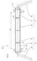
- Fig. 1 is shown in a view from below a driven rear axle for a motor vehicle, which is shown only insofar as it is necessary for the understanding of the invention.
- the rear axle 1 has an auxiliary frame 5, which is composed of longitudinal beams 7 and of front and rear cross members 9.
- the subframe 5 is in a conventional manner to only dashed lines indicated body side member 6 of the vehicle body 11 (only in the replacement model of Fig. 3 indicated).
- the subframe 5 carries only indicated by dashed lines rear axle differential 13, which is connected via a partially shown propeller shaft 15 with a front axle drive of the vehicle in combination.
- the rear axle differential 13 is via drive shafts 17 in drive connection with rear wheels of the vehicle, not shown.
- each lower link 14, 16, 18 and upper link 20, 22 articulated in a spatially staggered arrangement not shown arm bearings for the suspension on the two sides of the vehicle.
- the links 14 to 22 extend in the vehicle transverse direction y outwards to the respective wheel carriers 23, each having a right / left rear wheel 25 (only in the Fig. 3 indicated) of the motor vehicle carries.
- the above-described construction of the rear axle is mirror-symmetrical with respect to a vertical vehicle center longitudinal plane 27.
- the rear axle 1 has a torsion bar system 29 for active chassis control.
- the torsion bar system 29 has a rotary actuator 31 for each vehicle side.
- Each of the rotary actuators 31 is constructed by a motor-gear unit 35, a torsion spring member 37 and a driven lever 39.
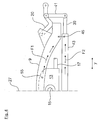
- the output lever 39 is according to the Fig. 4 via a coupling rod 41 in articulated connection with the upper lever 20.
- the components of the torsion bar system 29, with the exception of the torsionally stiff output lever 39 are arranged within a common housing 43.
- the housing 43 is mounted on bearing brackets 45 on the underside of the subframe, directly below the front subframe cross member 9.
- the common housing 43 and the two bearing brackets 45 are each arranged mirror-symmetrically to the vehicle longitudinal center plane 27, wherein the two bearing brackets 45 over a bearing distance .DELTA.y are spaced from each other, and are positioned approximately at front corner nodes of the subframe 5.
- the two motor-gear units 35 are each rotatably mounted within the common housing 43.
- Each of the motor-gear units 35 is connected via a rotatably mounted in a bearing 47 output shaft with the torsion spring member 37 (that is, a rotation spring), which is connected on the output side of the output lever 39. This in turn is rotatably guided by a housing opening 51 to the outside.
- the torsion spring elements 37 and the two motor-gear units are arranged with their axes of rotation to each other coaxially in series, whereby the overall diameter of the cylindrical common housing 43 is comparatively small.
- the interaction of the rotary actuator 31 of the torsion bar system 29 with in the Fig. 1 only indicated suspension spring 53 of the suspension of the rear axle 1 shown.
- the Suspension spring 53 and the torsion spring element 37 as a parallel spring system effective, which determines the total spring rate of the vehicle.
- the rear axle differential 13 is mounted at attachment points 55 on the front subframe cross member 9.
- the two connection points 55 of the rear differential 13 are located in the vehicle transverse direction y viewed between the mounting brackets 45 of the common housing 43rd
- the front subframe cross member 9 When driving, thus, the front subframe cross member 9 provides a load path F1, over which the operating forces are transferred to subframe side member.
- the common housing 7 is screwed to form node points with the front subframe cross member 9.
- a second load path F2 is provided. Over the second load path F2, the operating forces are introduced into the subframe side member 7 while reducing the load on the subframe cross member 9.
Landscapes
- Engineering & Computer Science (AREA)
- Mechanical Engineering (AREA)
- Vehicle Body Suspensions (AREA)
Claims (5)
- Carrosserie de véhicule et système de barre de torsion pour un essieu de véhicule (1), en particulier un essieu arrière, d'un véhicule à essieu, avec des premiers et deuxièmes actionneurs rotatifs (31) qui sont associés chacun à un côté de véhicule et destinés à un réglage actif de châssis et parmi lesquels chaque actionneur rotatif (31) comporte au moins une unité moteur-transmission (35) avec laquelle des couples peuvent être produits et transmis par l'intermédiaire d'un levier de sortie (39) à un élément de suspension de roue (20) comme forces de réglage, dans lesquels les unités moteur-transmission (35) des deux actionneurs rotatifs (31) sont agencées dans un carter commun (43) qui est monté, solidaire en rotation, sur la carrosserie de véhicule (11), dans lesquels, afin de rigidifier la carrosserie de véhicule (11), le carter (43) comporte au moins deux points d'attache (45) qui sont à une certaine distance l'un de l'autre par le biais d'une distance de palier (Δy) et par l'intermédiaire desquels le carter (43) est monté comme un élément de construction rigide sur la carrosserie de véhicule (11), dans lesquels la carrosserie de véhicule (11) comporte un faux-châssis (5) sur lequel le carter commun (43) est monté, dans lesquels le faux-châssis (5) comporte deux poutres longitudinales (7) et dans lesquels, pour former un faux-châssis (5) fermé en forme de cadre, il est prévu une poutre transversale avant et une poutre transversale arrière (9) qui sont reliées l'une à l'autre par l'intermédiaire des poutres longitudinales (7), caractérisés en ce que le carter commun (43) est agencé de manière à être aligné dans la direction verticale sous la poutre transversale avant (9) du faux-châssis (5) et ce en formant une double poutre telle que le carter commun (43) est monté comme une traverse supplémentaire sur le faux-châssis (5), et en ce que la poutre transversale avant (9) du faux-châssis (5) comporte un point d'attache (55) destiné à un composant d'entraînement (13), et en ce que le point d'attache (55) destiné au composant d'entraînement (13) est agencé, dans la direction transversale de véhicule (y), entre les points d'attache (45) du carter commun (43).
- Carrosserie de véhicule et système de barre de torsion selon la revendication 1, caractérisés en ce que chacune des unités moteur-transmission (35) comporte un élément de ressort de torsion (37) destiné au réglage d'une raideur de ressort du système de barre de torsion (29) et en ce qu'au moins l'un des éléments de ressort de torsion (37) est agencé à l'intérieur du carter commun (43).
- Carrosserie de véhicule et système de barre de torsion selon la revendication 1 ou 2, caractérisés en ce que le carter commun (43) comporte des ouvertures de carter (51) latérales dans la direction transversale de véhicule (y), ouvertures hors desquelles est guidé vers l'extérieur à chaque fois l'un des leviers de sortie (39) et en ce que les ouvertures de carter (51) sont des points d'appui de rotation qui définissent un axe de rotation du levier de sortie (39).
- Carrosserie de véhicule et système de barre de torsion selon l'une quelconque des revendications précédentes, caractérisés en ce que la poutre transversale avant (9) et/ou les deux poutres longitudinales (7) comportent des points d'appui au niveau desquels le carter commun (43) peut être fixé avec ses deux points d'attache (45).
- Carrosserie de véhicule et système de barre de torsion selon l'une quelconque des revendications précédentes, caractérisés en ce que la poutre transversale avant (9) fournit un premier cheminement de charges (F1) par lequel des forces de fonctionnement peuvent être introduites dans les poutres longitudinales (7) latérales de faux-châssis et en ce que le carter commun (43) fournit un deuxième cheminement de charges (F2) par lequel les forces de fonctionnement peuvent être introduites dans les poutres longitudinales (7).
Applications Claiming Priority (2)
| Application Number | Priority Date | Filing Date | Title |
|---|---|---|---|
| DE102013002704.7A DE102013002704A1 (de) | 2013-02-16 | 2013-02-16 | Drehstabsystem für eine Fahrzeugachse eines zweispurigen Fahrzeuges |
| PCT/EP2014/000390 WO2014124752A1 (fr) | 2013-02-16 | 2014-02-13 | Système de barre de torsion destiné à un essieu d'un véhicule à deux voies |
Publications (2)
| Publication Number | Publication Date |
|---|---|
| EP2956320A1 EP2956320A1 (fr) | 2015-12-23 |
| EP2956320B1 true EP2956320B1 (fr) | 2018-04-11 |
Family
ID=50190395
Family Applications (1)
| Application Number | Title | Priority Date | Filing Date |
|---|---|---|---|
| EP14707320.9A Active EP2956320B1 (fr) | 2013-02-16 | 2014-02-13 | Carrosserie de vehicule et système de barre de torsion destiné à un essieu d'un véhicule à deux voies |
Country Status (5)
| Country | Link |
|---|---|
| US (1) | US9434230B2 (fr) |
| EP (1) | EP2956320B1 (fr) |
| CN (1) | CN105073457B (fr) |
| DE (1) | DE102013002704A1 (fr) |
| WO (1) | WO2014124752A1 (fr) |
Families Citing this family (17)
| Publication number | Priority date | Publication date | Assignee | Title |
|---|---|---|---|---|
| DE102014005594A1 (de) | 2014-04-15 | 2015-10-15 | Audi Ag | Verfahren zum Kontrollieren eines Federungssystems |
| DE102014010287B3 (de) | 2014-07-11 | 2015-06-25 | Audi Ag | Hilfsrahmen für ein Kraftfahrzeug |
| JP6102951B2 (ja) * | 2015-01-16 | 2017-03-29 | マツダ株式会社 | 車両のサブフレーム構造 |
| JP6102952B2 (ja) * | 2015-01-16 | 2017-03-29 | マツダ株式会社 | 車両のサブフレーム構造 |
| DE102015103354B4 (de) * | 2015-03-06 | 2022-02-17 | Ovalo Gmbh | Aktive Stabilisatorvorrichtung für ein Fahrzeug |
| CN104773045B (zh) * | 2015-04-27 | 2017-11-14 | 席玉林 | 组合弹簧补偿悬挂装置 |
| DE102015015613B3 (de) * | 2015-12-03 | 2016-11-03 | Audi Ag | Radaufhängung für ein Kraftfahrzeug |
| DE102016000670B3 (de) | 2016-01-22 | 2017-01-12 | Audi Ag | Hilfsrahmen für ein zweispuriges Kraftfahrzeug |
| EP3409517B1 (fr) * | 2017-06-02 | 2022-04-13 | Ovalo GmbH | Suspension actif |
| US10518627B2 (en) * | 2018-06-05 | 2019-12-31 | Ford Global Technologies, Llc | Electric machine integrated axle assemblies for electrified vehicles |
| DE102018210637A1 (de) * | 2018-06-28 | 2020-01-02 | Zf Friedrichshafen Ag | Aktuatoreinrichtung für einen verstellbaren Wankstabilisator eines Kraftfahrzeugs |
| DE102018214289A1 (de) * | 2018-08-23 | 2020-02-27 | Bayerische Motoren Werke Aktiengesellschaft | Hinterachse eines Fahrzeuges |
| US11192414B1 (en) | 2020-10-13 | 2021-12-07 | Xtravel Suspension, Llc | Suspension system |
| US11571939B2 (en) | 2020-10-13 | 2023-02-07 | Xtravel Suspension, Llc | Suspension system |
| US20220250430A1 (en) * | 2021-02-11 | 2022-08-11 | GM Global Technology Operations LLC | Multilink mid-height suspension assembly for motor vehicles |
| US11511581B1 (en) | 2021-06-16 | 2022-11-29 | Xtravel Suspension, Llc | Suspension system |
| JP7727498B2 (ja) * | 2021-11-17 | 2025-08-21 | 株式会社Subaru | サスペンション装置 |
Family Cites Families (29)
| Publication number | Priority date | Publication date | Assignee | Title |
|---|---|---|---|---|
| US4648620A (en) * | 1985-05-20 | 1987-03-10 | Ford Motor Company | Adjustable suspension stabilizer bar |
| IN171681B (fr) * | 1987-10-05 | 1992-12-05 | Thor Sa | |
| JP3330726B2 (ja) * | 1994-03-31 | 2002-09-30 | マツダ株式会社 | 車両のサスペンション装置 |
| SE508519C2 (sv) | 1994-06-28 | 1998-10-12 | Volvo Ab | Hjulupphängning för ett par drivna fordonshjul |
| US5697847A (en) * | 1995-11-22 | 1997-12-16 | Eaton Corporation | Torsion bar drive coupling |
| US6832772B2 (en) * | 2001-10-26 | 2004-12-21 | Peterson & Erb | Vehicle center section adjustable anti-roll bar |
| JP3912180B2 (ja) * | 2002-05-22 | 2007-05-09 | マツダ株式会社 | 自動車の後輪サスペンション装置 |
| US7234713B1 (en) * | 2003-02-21 | 2007-06-26 | Link Mfg. Ltd. | Axle suspension system |
| DE102004004335B4 (de) | 2004-01-29 | 2017-07-13 | Zf Friedrichshafen Ag | Fahrwerksanordnung für ein Fahrzeug |
| JP4247902B2 (ja) * | 2004-03-31 | 2009-04-02 | 本田技研工業株式会社 | ブッシュ取付構造 |
| EP2263890B1 (fr) * | 2004-03-31 | 2014-03-12 | Honda Motor Co., Ltd. | Berceau de véhicule et arrangement d'un manchon pour ce dernier |
| US7850181B2 (en) * | 2004-09-23 | 2010-12-14 | Axletech International Ip Holdings, Llc | Independent suspension with adjustable sub-frame |
| JP4193819B2 (ja) * | 2005-06-27 | 2008-12-10 | トヨタ自動車株式会社 | 車両用懸架装置 |
| DE102006004960A1 (de) * | 2006-02-01 | 2007-08-09 | Zf Friedrichshafen Ag | Angetriebe Fahrzeugachse mit Einzelradaufhängung |
| DE102006006929A1 (de) * | 2006-02-14 | 2007-08-16 | Muhr Und Bender Kg | Koppelstange für eine Stabilisatoranordnung |
| DE202006016344U1 (de) | 2006-10-23 | 2008-02-28 | Asturia Automotive Systems Ag | Akuatorsystem |
| DE102008010551A1 (de) * | 2008-02-22 | 2009-08-27 | Dr. Ing. H.C. F. Porsche Aktiengesellschaft | Fahrschemel für eine Hinterachse eines Kraftfahrzeugs |
| DE102008002524A1 (de) * | 2008-06-19 | 2009-12-24 | Zf Friedrichshafen Ag | Stabilisator für ein Nutzfahrzeug |
| DE102008064498A1 (de) | 2008-12-23 | 2010-07-01 | Siemens Aktiengesellschaft | Elektrische Maschine mit radial versetztem Kühlstrom und Kühlverfahren |
| DE102008064495B3 (de) | 2008-12-23 | 2010-10-21 | Siemens Aktiengesellschaft | Elektrische Maschine mit mehreren Kühlströmen und Kühlverfahren |
| DE102009005899A1 (de) * | 2009-01-23 | 2010-07-29 | Audi Ag | Anordnung eines Stabilisators an einer Radaufhängung für Kraftfahrzeuge |
| DE102009005898A1 (de) | 2009-01-23 | 2010-07-29 | Audi Ag | Anordnung eines Stabilisators an einer Radaufhängung für Kraftfahrzeuge |
| DE102009005895A1 (de) * | 2009-01-23 | 2010-07-29 | Audi Ag | Anordnung eines Stabilisators an einer Radaufhängung für Kraftfahrzeuge |
| US8505888B2 (en) * | 2009-12-01 | 2013-08-13 | Impulse Composites, Llc | Tubular torsion bar |
| DE102010039871A1 (de) | 2010-08-27 | 2012-03-01 | Siemens Aktiengesellschaft | Aktivteil einer elektrischen Maschine mit schrägen Spulen im Wickelkopfbereich |
| DE102011018574A1 (de) | 2011-04-26 | 2012-10-31 | Audi Ag | Federungsanordnung für Radaufhängungen von Kraftfahrzeugen |
| DE102012023363B4 (de) | 2012-11-29 | 2014-06-26 | Audi Ag | Hilfsrahmen für ein Kraftfahrzeug |
| DE102013002713B4 (de) | 2013-02-16 | 2014-08-28 | Audi Ag | Drehstabfederanordnung für eine Radaufhängung eines Kraftfahrzeugs |
| DE102013007355A1 (de) | 2013-04-27 | 2014-10-30 | Audi Ag | Radaufhängung für ein Kraftfahrzeug |
-
2013
- 2013-02-16 DE DE102013002704.7A patent/DE102013002704A1/de not_active Withdrawn
-
2014
- 2014-02-13 WO PCT/EP2014/000390 patent/WO2014124752A1/fr not_active Ceased
- 2014-02-13 US US14/767,947 patent/US9434230B2/en active Active
- 2014-02-13 EP EP14707320.9A patent/EP2956320B1/fr active Active
- 2014-02-13 CN CN201480008706.0A patent/CN105073457B/zh active Active
Also Published As
| Publication number | Publication date |
|---|---|
| WO2014124752A1 (fr) | 2014-08-21 |
| CN105073457B (zh) | 2017-08-01 |
| US9434230B2 (en) | 2016-09-06 |
| US20150367705A1 (en) | 2015-12-24 |
| EP2956320A1 (fr) | 2015-12-23 |
| DE102013002704A1 (de) | 2014-08-21 |
| CN105073457A (zh) | 2015-11-18 |
Similar Documents
| Publication | Publication Date | Title |
|---|---|---|
| EP2956320B1 (fr) | Carrosserie de vehicule et système de barre de torsion destiné à un essieu d'un véhicule à deux voies | |
| EP2796307B1 (fr) | Suspension de roue pour un véhicule automobile | |
| EP2823976B1 (fr) | Faux-châssis pour un véhicule automobile | |
| EP2956315B1 (fr) | Suspension de roue conçue pour un véhicule automobile | |
| EP2517905B1 (fr) | Agencement de ressort pour suspensions de roues de véhicules automobiles | |
| EP2493708B1 (fr) | Suspension de véhicule | |
| EP2956319B1 (fr) | Système de barre de torsion conçu pour une suspension de roue d'un véhicule automobile | |
| DE102014205632A1 (de) | Einzelradaufhängung sowie Hinterachse mit Einzelradaufhängungen für ein Fahrzeug und entsprechend ausgestattetes Fahrzeug | |
| DE102014102510A1 (de) | Hinterradaufhängungs-Unterbaugruppe für ein Kraftfahrzeug | |
| DE102016014004A1 (de) | Tandemachse | |
| DE102014205635A1 (de) | Einzelradaufhängung sowie Hinterachse mit Einzelradaufhängungen für ein Fahrzeug und entsprechend ausgestattetes Fahrzeug | |
| AT524936B1 (de) | Plattform für mindestens vierrädrige Kraftfahrzeuge mit Elektroantrieb | |
| EP2473393B1 (fr) | Carrosserie de véhicule à ensemble pont arrière modulaire | |
| DE202014101432U1 (de) | Einzelradaufhängung sowie Hinterachse mit Einzelradaufhängungen für ein Fahrzeug und entsprechend ausgestattetes Fahrzeug | |
| DE102013007982B3 (de) | Drehstabfedersystem für eine Radaufhängung eines Fahrzeuges | |
| DE102015202208B4 (de) | Verfahren zum Betrieb einer Hinterradlenkung sowie Hinterradlenkung für ein Fahrzeug | |
| DE102006013547B4 (de) | Hilfsrahmen für Kraftfahrzeuge sowie ein Verfahren zur Montage von Antriebsaggregaten von Kraftfahrzeugen auf solchen Hilfsrahmen | |
| DE102014200295A1 (de) | Lageranordnung für eine Verbundlenkerachse sowie Verbundlenkerachse | |
| DE102016216899A1 (de) | Radaufhängung für ein zweispuriges Fahrzeug | |
| DE102009016935A1 (de) | Querträger für Kraftfahrzeuge | |
| DE102013002703B4 (de) | Drehfedersystem für eine Fahrzeugachse | |
| AT525085B1 (de) | Plattform für mindestens vierrädrige Kraftfahrzeuge mit Elektroantrieb | |
| DE102016006945B3 (de) | Hilfsrahmen für ein Kraftfahrzeug | |
| DE102015202209A1 (de) | Verfahren zum Betrieb einer Hinterradlenkung sowie Hinterradlenkung für ein Fahrzeug | |
| DE202015100960U1 (de) | Hinterradlenkung für ein Fahrzeug |
Legal Events
| Date | Code | Title | Description |
|---|---|---|---|
| PUAI | Public reference made under article 153(3) epc to a published international application that has entered the european phase |
Free format text: ORIGINAL CODE: 0009012 |
|
| 17P | Request for examination filed |
Effective date: 20150916 |
|
| AK | Designated contracting states |
Kind code of ref document: A1 Designated state(s): AL AT BE BG CH CY CZ DE DK EE ES FI FR GB GR HR HU IE IS IT LI LT LU LV MC MK MT NL NO PL PT RO RS SE SI SK SM TR |
|
| AX | Request for extension of the european patent |
Extension state: BA ME |
|
| DAX | Request for extension of the european patent (deleted) | ||
| GRAP | Despatch of communication of intention to grant a patent |
Free format text: ORIGINAL CODE: EPIDOSNIGR1 |
|
| STAA | Information on the status of an ep patent application or granted ep patent |
Free format text: STATUS: GRANT OF PATENT IS INTENDED |
|
| INTG | Intention to grant announced |
Effective date: 20180115 |
|
| GRAS | Grant fee paid |
Free format text: ORIGINAL CODE: EPIDOSNIGR3 |
|
| GRAA | (expected) grant |
Free format text: ORIGINAL CODE: 0009210 |
|
| STAA | Information on the status of an ep patent application or granted ep patent |
Free format text: STATUS: THE PATENT HAS BEEN GRANTED |
|
| AK | Designated contracting states |
Kind code of ref document: B1 Designated state(s): AL AT BE BG CH CY CZ DE DK EE ES FI FR GB GR HR HU IE IS IT LI LT LU LV MC MK MT NL NO PL PT RO RS SE SI SK SM TR |
|
| REG | Reference to a national code |
Ref country code: GB Ref legal event code: FG4D Free format text: NOT ENGLISH |
|
| REG | Reference to a national code |
Ref country code: CH Ref legal event code: EP |
|
| REG | Reference to a national code |
Ref country code: AT Ref legal event code: REF Ref document number: 987629 Country of ref document: AT Kind code of ref document: T Effective date: 20180415 |
|
| REG | Reference to a national code |
Ref country code: IE Ref legal event code: FG4D Free format text: LANGUAGE OF EP DOCUMENT: GERMAN |
|
| REG | Reference to a national code |
Ref country code: DE Ref legal event code: R096 Ref document number: 502014007930 Country of ref document: DE |
|
| REG | Reference to a national code |
Ref country code: NL Ref legal event code: MP Effective date: 20180411 |
|
| REG | Reference to a national code |
Ref country code: LT Ref legal event code: MG4D |
|
| PG25 | Lapsed in a contracting state [announced via postgrant information from national office to epo] |
Ref country code: NL Free format text: LAPSE BECAUSE OF FAILURE TO SUBMIT A TRANSLATION OF THE DESCRIPTION OR TO PAY THE FEE WITHIN THE PRESCRIBED TIME-LIMIT Effective date: 20180411 |
|
| PG25 | Lapsed in a contracting state [announced via postgrant information from national office to epo] |
Ref country code: ES Free format text: LAPSE BECAUSE OF FAILURE TO SUBMIT A TRANSLATION OF THE DESCRIPTION OR TO PAY THE FEE WITHIN THE PRESCRIBED TIME-LIMIT Effective date: 20180411 Ref country code: PL Free format text: LAPSE BECAUSE OF FAILURE TO SUBMIT A TRANSLATION OF THE DESCRIPTION OR TO PAY THE FEE WITHIN THE PRESCRIBED TIME-LIMIT Effective date: 20180411 Ref country code: NO Free format text: LAPSE BECAUSE OF FAILURE TO SUBMIT A TRANSLATION OF THE DESCRIPTION OR TO PAY THE FEE WITHIN THE PRESCRIBED TIME-LIMIT Effective date: 20180711 Ref country code: AL Free format text: LAPSE BECAUSE OF FAILURE TO SUBMIT A TRANSLATION OF THE DESCRIPTION OR TO PAY THE FEE WITHIN THE PRESCRIBED TIME-LIMIT Effective date: 20180411 Ref country code: SE Free format text: LAPSE BECAUSE OF FAILURE TO SUBMIT A TRANSLATION OF THE DESCRIPTION OR TO PAY THE FEE WITHIN THE PRESCRIBED TIME-LIMIT Effective date: 20180411 Ref country code: FI Free format text: LAPSE BECAUSE OF FAILURE TO SUBMIT A TRANSLATION OF THE DESCRIPTION OR TO PAY THE FEE WITHIN THE PRESCRIBED TIME-LIMIT Effective date: 20180411 Ref country code: BG Free format text: LAPSE BECAUSE OF FAILURE TO SUBMIT A TRANSLATION OF THE DESCRIPTION OR TO PAY THE FEE WITHIN THE PRESCRIBED TIME-LIMIT Effective date: 20180711 Ref country code: LT Free format text: LAPSE BECAUSE OF FAILURE TO SUBMIT A TRANSLATION OF THE DESCRIPTION OR TO PAY THE FEE WITHIN THE PRESCRIBED TIME-LIMIT Effective date: 20180411 |
|
| PG25 | Lapsed in a contracting state [announced via postgrant information from national office to epo] |
Ref country code: LV Free format text: LAPSE BECAUSE OF FAILURE TO SUBMIT A TRANSLATION OF THE DESCRIPTION OR TO PAY THE FEE WITHIN THE PRESCRIBED TIME-LIMIT Effective date: 20180411 Ref country code: RS Free format text: LAPSE BECAUSE OF FAILURE TO SUBMIT A TRANSLATION OF THE DESCRIPTION OR TO PAY THE FEE WITHIN THE PRESCRIBED TIME-LIMIT Effective date: 20180411 Ref country code: HR Free format text: LAPSE BECAUSE OF FAILURE TO SUBMIT A TRANSLATION OF THE DESCRIPTION OR TO PAY THE FEE WITHIN THE PRESCRIBED TIME-LIMIT Effective date: 20180411 Ref country code: GR Free format text: LAPSE BECAUSE OF FAILURE TO SUBMIT A TRANSLATION OF THE DESCRIPTION OR TO PAY THE FEE WITHIN THE PRESCRIBED TIME-LIMIT Effective date: 20180712 |
|
| PG25 | Lapsed in a contracting state [announced via postgrant information from national office to epo] |
Ref country code: PT Free format text: LAPSE BECAUSE OF FAILURE TO SUBMIT A TRANSLATION OF THE DESCRIPTION OR TO PAY THE FEE WITHIN THE PRESCRIBED TIME-LIMIT Effective date: 20180813 |
|
| REG | Reference to a national code |
Ref country code: DE Ref legal event code: R097 Ref document number: 502014007930 Country of ref document: DE |
|
| PG25 | Lapsed in a contracting state [announced via postgrant information from national office to epo] |
Ref country code: CZ Free format text: LAPSE BECAUSE OF FAILURE TO SUBMIT A TRANSLATION OF THE DESCRIPTION OR TO PAY THE FEE WITHIN THE PRESCRIBED TIME-LIMIT Effective date: 20180411 Ref country code: RO Free format text: LAPSE BECAUSE OF FAILURE TO SUBMIT A TRANSLATION OF THE DESCRIPTION OR TO PAY THE FEE WITHIN THE PRESCRIBED TIME-LIMIT Effective date: 20180411 Ref country code: DK Free format text: LAPSE BECAUSE OF FAILURE TO SUBMIT A TRANSLATION OF THE DESCRIPTION OR TO PAY THE FEE WITHIN THE PRESCRIBED TIME-LIMIT Effective date: 20180411 Ref country code: EE Free format text: LAPSE BECAUSE OF FAILURE TO SUBMIT A TRANSLATION OF THE DESCRIPTION OR TO PAY THE FEE WITHIN THE PRESCRIBED TIME-LIMIT Effective date: 20180411 Ref country code: SK Free format text: LAPSE BECAUSE OF FAILURE TO SUBMIT A TRANSLATION OF THE DESCRIPTION OR TO PAY THE FEE WITHIN THE PRESCRIBED TIME-LIMIT Effective date: 20180411 |
|
| PLBE | No opposition filed within time limit |
Free format text: ORIGINAL CODE: 0009261 |
|
| STAA | Information on the status of an ep patent application or granted ep patent |
Free format text: STATUS: NO OPPOSITION FILED WITHIN TIME LIMIT |
|
| PG25 | Lapsed in a contracting state [announced via postgrant information from national office to epo] |
Ref country code: IT Free format text: LAPSE BECAUSE OF FAILURE TO SUBMIT A TRANSLATION OF THE DESCRIPTION OR TO PAY THE FEE WITHIN THE PRESCRIBED TIME-LIMIT Effective date: 20180411 Ref country code: SM Free format text: LAPSE BECAUSE OF FAILURE TO SUBMIT A TRANSLATION OF THE DESCRIPTION OR TO PAY THE FEE WITHIN THE PRESCRIBED TIME-LIMIT Effective date: 20180411 |
|
| 26N | No opposition filed |
Effective date: 20190114 |
|
| PG25 | Lapsed in a contracting state [announced via postgrant information from national office to epo] |
Ref country code: SI Free format text: LAPSE BECAUSE OF FAILURE TO SUBMIT A TRANSLATION OF THE DESCRIPTION OR TO PAY THE FEE WITHIN THE PRESCRIBED TIME-LIMIT Effective date: 20180411 |
|
| REG | Reference to a national code |
Ref country code: CH Ref legal event code: PL |
|
| PG25 | Lapsed in a contracting state [announced via postgrant information from national office to epo] |
Ref country code: MC Free format text: LAPSE BECAUSE OF FAILURE TO SUBMIT A TRANSLATION OF THE DESCRIPTION OR TO PAY THE FEE WITHIN THE PRESCRIBED TIME-LIMIT Effective date: 20180411 Ref country code: LU Free format text: LAPSE BECAUSE OF NON-PAYMENT OF DUE FEES Effective date: 20190213 |
|
| REG | Reference to a national code |
Ref country code: BE Ref legal event code: MM Effective date: 20190228 |
|
| REG | Reference to a national code |
Ref country code: IE Ref legal event code: MM4A |
|
| PG25 | Lapsed in a contracting state [announced via postgrant information from national office to epo] |
Ref country code: CH Free format text: LAPSE BECAUSE OF NON-PAYMENT OF DUE FEES Effective date: 20190228 Ref country code: LI Free format text: LAPSE BECAUSE OF NON-PAYMENT OF DUE FEES Effective date: 20190228 |
|
| PG25 | Lapsed in a contracting state [announced via postgrant information from national office to epo] |
Ref country code: IE Free format text: LAPSE BECAUSE OF NON-PAYMENT OF DUE FEES Effective date: 20190213 |
|
| PG25 | Lapsed in a contracting state [announced via postgrant information from national office to epo] |
Ref country code: BE Free format text: LAPSE BECAUSE OF NON-PAYMENT OF DUE FEES Effective date: 20190228 |
|
| PG25 | Lapsed in a contracting state [announced via postgrant information from national office to epo] |
Ref country code: TR Free format text: LAPSE BECAUSE OF FAILURE TO SUBMIT A TRANSLATION OF THE DESCRIPTION OR TO PAY THE FEE WITHIN THE PRESCRIBED TIME-LIMIT Effective date: 20180411 |
|
| REG | Reference to a national code |
Ref country code: AT Ref legal event code: MM01 Ref document number: 987629 Country of ref document: AT Kind code of ref document: T Effective date: 20190213 |
|
| PG25 | Lapsed in a contracting state [announced via postgrant information from national office to epo] |
Ref country code: AT Free format text: LAPSE BECAUSE OF NON-PAYMENT OF DUE FEES Effective date: 20190213 |
|
| PG25 | Lapsed in a contracting state [announced via postgrant information from national office to epo] |
Ref country code: MT Free format text: LAPSE BECAUSE OF FAILURE TO SUBMIT A TRANSLATION OF THE DESCRIPTION OR TO PAY THE FEE WITHIN THE PRESCRIBED TIME-LIMIT Effective date: 20180411 |
|
| PG25 | Lapsed in a contracting state [announced via postgrant information from national office to epo] |
Ref country code: CY Free format text: LAPSE BECAUSE OF FAILURE TO SUBMIT A TRANSLATION OF THE DESCRIPTION OR TO PAY THE FEE WITHIN THE PRESCRIBED TIME-LIMIT Effective date: 20180411 |
|
| PG25 | Lapsed in a contracting state [announced via postgrant information from national office to epo] |
Ref country code: IS Free format text: LAPSE BECAUSE OF FAILURE TO SUBMIT A TRANSLATION OF THE DESCRIPTION OR TO PAY THE FEE WITHIN THE PRESCRIBED TIME-LIMIT Effective date: 20180811 |
|
| PG25 | Lapsed in a contracting state [announced via postgrant information from national office to epo] |
Ref country code: HU Free format text: LAPSE BECAUSE OF FAILURE TO SUBMIT A TRANSLATION OF THE DESCRIPTION OR TO PAY THE FEE WITHIN THE PRESCRIBED TIME-LIMIT; INVALID AB INITIO Effective date: 20140213 |
|
| PG25 | Lapsed in a contracting state [announced via postgrant information from national office to epo] |
Ref country code: MK Free format text: LAPSE BECAUSE OF FAILURE TO SUBMIT A TRANSLATION OF THE DESCRIPTION OR TO PAY THE FEE WITHIN THE PRESCRIBED TIME-LIMIT Effective date: 20180411 |
|
| P01 | Opt-out of the competence of the unified patent court (upc) registered |
Effective date: 20230530 |
|
| PGFP | Annual fee paid to national office [announced via postgrant information from national office to epo] |
Ref country code: DE Payment date: 20250228 Year of fee payment: 12 |
|
| PGFP | Annual fee paid to national office [announced via postgrant information from national office to epo] |
Ref country code: FR Payment date: 20250218 Year of fee payment: 12 |
|
| PGFP | Annual fee paid to national office [announced via postgrant information from national office to epo] |
Ref country code: GB Payment date: 20250221 Year of fee payment: 12 |