EP2956586B1 - Lärmschutzwand und konstruktionsverfahren dafür - Google Patents
Lärmschutzwand und konstruktionsverfahren dafür Download PDFInfo
- Publication number
- EP2956586B1 EP2956586B1 EP14782785.1A EP14782785A EP2956586B1 EP 2956586 B1 EP2956586 B1 EP 2956586B1 EP 14782785 A EP14782785 A EP 14782785A EP 2956586 B1 EP2956586 B1 EP 2956586B1
- Authority
- EP
- European Patent Office
- Prior art keywords
- noise barrier
- barrier panel
- noise
- panel
- mounting
- Prior art date
- Legal status (The legal status is an assumption and is not a legal conclusion. Google has not performed a legal analysis and makes no representation as to the accuracy of the status listed.)
- Active
Links
Images











Classifications
-
- E—FIXED CONSTRUCTIONS
- E04—BUILDING
- E04B—GENERAL BUILDING CONSTRUCTIONS; WALLS, e.g. PARTITIONS; ROOFS; FLOORS; CEILINGS; INSULATION OR OTHER PROTECTION OF BUILDINGS
- E04B1/00—Constructions in general; Structures which are not restricted either to walls, e.g. partitions, or floors or ceilings or roofs
- E04B1/99—Room acoustics, i.e. forms of, or arrangements in, rooms for influencing or directing sound
- E04B1/994—Acoustical surfaces with adjustment mechanisms
-
- E—FIXED CONSTRUCTIONS
- E01—CONSTRUCTION OF ROADS, RAILWAYS, OR BRIDGES
- E01F—ADDITIONAL WORK, SUCH AS EQUIPPING ROADS OR THE CONSTRUCTION OF PLATFORMS, HELICOPTER LANDING STAGES, SIGNS, SNOW FENCES, OR THE LIKE
- E01F8/00—Arrangements for absorbing or reflecting air-transmitted noise from road or railway traffic
- E01F8/0005—Arrangements for absorbing or reflecting air-transmitted noise from road or railway traffic used in a wall type arrangement
- E01F8/0011—Plank-like elements
-
- E—FIXED CONSTRUCTIONS
- E01—CONSTRUCTION OF ROADS, RAILWAYS, OR BRIDGES
- E01F—ADDITIONAL WORK, SUCH AS EQUIPPING ROADS OR THE CONSTRUCTION OF PLATFORMS, HELICOPTER LANDING STAGES, SIGNS, SNOW FENCES, OR THE LIKE
- E01F8/00—Arrangements for absorbing or reflecting air-transmitted noise from road or railway traffic
- E01F8/0005—Arrangements for absorbing or reflecting air-transmitted noise from road or railway traffic used in a wall type arrangement
- E01F8/0088—Suspended, e.g. ropes or mesh
-
- Y—GENERAL TAGGING OF NEW TECHNOLOGICAL DEVELOPMENTS; GENERAL TAGGING OF CROSS-SECTIONAL TECHNOLOGIES SPANNING OVER SEVERAL SECTIONS OF THE IPC; TECHNICAL SUBJECTS COVERED BY FORMER USPC CROSS-REFERENCE ART COLLECTIONS [XRACs] AND DIGESTS
- Y10—TECHNICAL SUBJECTS COVERED BY FORMER USPC
- Y10T—TECHNICAL SUBJECTS COVERED BY FORMER US CLASSIFICATION
- Y10T29/00—Metal working
- Y10T29/49—Method of mechanical manufacture
- Y10T29/49826—Assembling or joining
Definitions
- This invention is related to noise barriers, and more particularly temporary noise barrier structures.
- Outdoor noise barriers have been erected next to construction sites for reducing construction noise from reaching nearby residential premises.
- a noise barrier responsive to wind loads is known from DE 26 14 568 A1 .
- Virtually all noise barriers have a large surface area for blocking and/or absorbing sound. In the outdoors, the wind loading on such noise barrier structure can be very high during occasional strong gusts.
- outdoor noise barriers are necessarily strong and heavy structures, constructed to withstand a wind load of 1 to 1.4kPa in general.
- a strong concrete foundation is usually required for tall noise barriers of 6m to 10m.
- the erection and mobilization of such heavy noise barriers are energy and labour intensive, and have to be done using cranes and elevated platforms. Dismantling these heavy structures is also energy and labour intensive. Therefore, when a noise barrier is erected, it is typically intended to be a strong structure to remain standing next to the construction site for a significant period of time.
- a noise barrier which is relatively easy to erect, mobilise and dismantle, and which may be used as a temporal structure for a short period of time and which may be able to avoid damaging the existing ground to erect the noise barrier.
- the noise barrier comprises at least two mounting poles forming a frame and at least one noise barrier panel which is placed across said frame and capable of being moved by the force of wind to allow passage of wind.
- the invention provides the possibility of reducing reduce wind load on the barrier structure during occasional strong gust, where such strong gust only occurs of once in a few months.
- the large surface area for blocking noise is capable of being reduced to allow wind to pass through the noise barrier. This effectively limits the wind load to be lower than that of a conventional noise barrier of the same surface area.
- the noise barrier does not have to be made of heavy material.
- the noise barrier can be made of light material. Constructing and dismantling a lightweight noise barrier can be easy, quick and suitable for temporary deployment. Use of cranes, elevated platforms, and concrete foundation is relieved. Noise barrier erection and mobilization can be even done quietly at night.
- the at least one noise barrier panel has a close position for providing barrier to noise, the at least one noise barrier panel has an open position to allow passage of wind, wherein the at least one noise barrier panel is capable of being moved by the force of wind from the closed position to the open position.
- the at least one noise barrier panel is capable of folding to move from the closed position to the open position.
- noise barrier panel of the noise barrier comprises preferably magnetic material for keeping the at least one noise barrier panel in the closed position. Using magnets improve the precision of positioning the noise barrier panel in the closed position.
- the at least one noise barrier panel has a first side having a first magnetic material; the at least one noise barrier panel has a second side having a second magnetic material; the second magnetic material of the second side of the at least one noise barrier panel being capable of magnetically cooperating with the first magnetic material of the first side of an adjacent noise barrier panel.
- the at least one noise barrier panel comprises an inflatable cushion. More preferably, the inflatable cushion contains plurality of inflatable segments. Segmenting the cushion prevents a bulge forming at the centre of the cushion. The gas pressure inside a plurality of inflatable segments provides an upright rigidity to the cushion, allowing the cushion to be held at one side while remaining upright to serve as a noise panel.
- the inflatable cushion contains a liquid capable of absorbing sound energy. This can improve the sound energy absorption capability of the noise barrier panel.
- the at least one noise barrier panel is mounted on one mounting pole to be slide-able along the mounting pole. This provides an advantage that a first noise barrier panel can be inserted at the bottom of a mounting pole, and then pushed up by a second noise barrier panel following the first noise barrier panel.
- An entire pole can be installed with a column of noise barrier panels manually, by a human operator pushing them upwardly from the ground. Even if a machine is required for a heavier embodiment, only a jack is needed to push the noise barrier panel from ground up. This relieves the need of any cranes or heavy machinery for installing noise barrier panels on a scaffolding to provide a noise barrier.
- a noise barrier panel for use in a noise barrier comprises an inflatable cushion suitable for mounting onto a mounting pole. Accordingly, the inflatable cushion can be supplied by any third party manufacturer as long as the dimensions comply to requirements for the mounting.
- the noise barrier panel comprises a first side having a first magnetic material, a second side having a second magnetic material, the second magnetic material of the second side of the at least one noise barrier panel being capable of magnetically cooperating with the first magnetic material of the first side of an adjacent noise barrier panel.
- a method of installing the noise barrier comprising the steps of: providing at least two mounting poles, providing a first noise barrier panel, mounting the first noise barrier panel onto at least one of the mounting poles, sliding the first noise barrier panel along the at least one mounting pole.
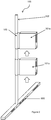
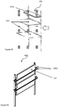
- Figure 1 is a schematic of an exploded view of a first embodiment, which is a noise barrier 100 having noise barrier panels 101 that can be blown open by wind. This limits the wind load on the noise barrier 100, mounting poles 102 and frame 103, as any instance of undesirably high wind load is reduced immediately when noise barrier panels 101 are blown open to reduce the noise barrier surface area facing the wind.
- the reduction of orthogonal surface area possibly reduces the wind load to one tenth or lower than that of an un-openable noise barrier. It should be noted that C d is also reduced at the barrier opened position.
- the noise barrier 100 Having a low wind load design allows the noise barrier 100 to be made of light weight material. As a result, the noise barrier can be constructed without need of heavy machinery and concrete foundation, and can be erected quickly even as a temporary structure that can be dismantled easily. Accordingly, the noise barrier 100 is capable of quick and temporary deployment near residential estates where installing conventional noise barrier with strong structure is not feasible or cost-effective.
- the noise barrier according to the invention comprises two basic parts, namely mounting poles 102 and noise barrier panels 101.
- Two mounting poles 102 together form a frame 103 across which a noise barrier panel 101 may be placed to absorb or block noise.
- the noise barrier panel 101 is a lightweight planar block having a surface for sound blocking and/or absorption.
- the block arrows show schematically that each noise barrier panel 101 can be mounted onto a mounting pole 102.
- Each noise barrier panel 101 has a sleeve 105 at one of its lateral sides, for slipping over and being moved along the mounting pole 102.
- the sleeve 105 is preferably made of a strong fabric or plastic, such as those used for parachutes or for military tents.
- the mounting poles 102 are preferably made of a strong and light material such as carbon fibre or aluminium.
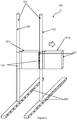
- Figure 2 shows the sleeve 105 of a noise barrier panel 101a enveloping the lower part of a mounting pole 102, at a height where a man can reach easily, and is pushed up on the mounting pole 102.
- a further noise barrier panel 101b can be attached to the mounting pole 102 in the same way below the first noise barrier panel 101.
- the block arrows show how pushing the lower noise barrier panel 101b upwards pushes the first noise barrier panel 101a higher on the pole.
- a sufficient number of noise barrier panels 101 are attached to a mounting pole 102 forming an assembled column of noise barrier panels 101 and providing a combined large surface area suitable for use as effective noise barrier 100.
- Figure 3 shows how a noise barrier panel 101c cooperates with an adjacent noise barrier panel 101d side-wise to extend the noise barrier 100 laterally.
- the sleeve 105 of each noise barrier panel 101 is installed with a magnetic material.
- the free-swinging vertical side 107 of the noise barrier panel 101, which is distal from the sleeve 105, is also installed with a magnetic material. Therefore, two laterally adjacent noise barrier panels 101c, 101d cooperate by the vertical side 107 of a first noise barrier panel 101c being in magnetic cooperation with the sleeve 105 of the adjacent noise barrier panel 101d.
- the magnetic cooperation keeps the noise barrier panels 101 stationary in a closed position under normal conditions, which forms a continual wall for blocking sound.
- each noise barrier panel 101 may swivel into an open position relative to the mounting pole 102 inserted through the panel sleeve 105. This reduces the wind load immediately. In other words, the swivelling noise barrier panel 101 limits the wind load on the noise barrier 100.
- Figure 4 shows how an end-pole 401 provides magnetic cooperation to keep the end-most column of noise barrier panels 101 in the closed position.
- the length of the end-pole 401 is installed with magnetic material.
- the free-swinging vertical sides 107 of the end column of noise barrier panels 101 are placed in magnetic cooperation with the end-pole 401, instead of the sleeves 105 of a further column of noise barrier panels 101.
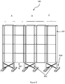
- Figure 5 shows an assembled wall of five columns of noise barrier panels 101 ended by an end-pole 401.
- Every two mounting poles 102 forming a frame 103 can be integrated using an X-shape cross-bar 500 at the bottom of the frame 103.
- every frame 103 forms the smallest unit of noise barrier 100 that can stand stably on two ground supports, whether the frame 103 has one or two columns of noise barrier panels 101.
- This smallest stable unit can be moved manually and easily.
- the end-pole 401 is not sleeved with any noise barrier panels101 and only provides magnetic cooperation with the free-swinging vertical sides 107 of the last column of noise barrier panels 101.
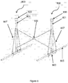
- Each mounting pole 102 is installed on a base 800.
- the base 800 can be seen in greater detail in Figure 6 showing a pair of bases joined by a cross bar 500.
- the base 800 is an inverted T-shape metal mounting, made up of a square tube 803 and a pole holder 801 extending upwardly from the square tube 803.
- a mounting pole 102 is inserted into the pole holder 801.
- the square tube 803 can be bolted to the ground for stability.
- each square tube 803 is inserted with a long ground pole 805 for more stability.
- Sandbags can also be placed on the square tube 803 for additional stability.
- Each base 800 has slanted tubes 807 between the square tube 803 and the pole holder 801 to provide rigidity for the T-shape base 800.
- the lowest noise barrier panel 101 on each mounting pole 102 is supported by a sleeve-ring.
- An illustration of the sleeve-ring 600 is shown in Figure 7 .
- the inner diameter of the sleeve-ring 600 allows the sleeve-ring 600 to be inserted over a mounting pole 102.
- the inner diameter of the sleeve-ring 600 is too small to slip over a pole holder 801 of a base 800. Therefore, the sleeve-ring 600 sits on the top of the pole holder 801 and supports an entire column of noise barrier panels 101 in turn sitting on the sleeve-ring 600.
- the gap 501 between the lowest noise barrier panels 101 of the noise barrier 100 and the ground is closed by flexible noise barrier mats or individual solid panels.
- the gap 501 is indicated in Figure 5 .
- Figure 8 shows two top noise barrier panels 101 swivelled by wind into the open position. This provides a wind load reduction mechanism; the opened noise barrier panels 101 provide wind passage through the noise barrier 100 and reduce the surface area facing the wind. In the closed position, the noise barrier is situated such that the panels 101 face the construction site and provide maximum noise insulation. Although the noise barrier panels 101 are illustrated as being moved into the page, the noise barrier panels 101 can swivel in any direction about the mounting pole 102 according to the wind direction.
- the minimum wind strength which can open a noise barrier panel 101 is a threshold determined by the strength of the magnetic and/or mechanical cooperation between two adjacent noise barrier panels 101.
- the threshold is preferably 0.02 to 0.3kPa, which corresponding to wind speeds of approximately 20 to 75kph directly heading on the noise barrier panel 101. This is approximately only 2% to 20% of the wind load required of conventional outdoor noise barriers.
- wind speed is below this threshold, the noise barrier panels can remain closed.
- one or more of the noise barrier panels can be blown open, immediately reducing the wind load on the noise barrier 100 as an automatic mechanism. In this way, the threshold limits the wind load on the noise barrier 100.
- the noise barrier panel 101 is small and lightweight.
- the surface of each noise barrier panel 101 for facing the construction site is typically less than 5m 2 to keep the noise barrier panel 101 small and manually manageable.
- the surface density of noise barrier panel 101 is preferably less than 3kg/m 2 , in order to keep the noise barrier panel 101 lightweight. In some other cases, the preferred surface density is around 1 to 2kg/m 2 .
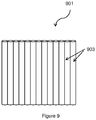
- Figure 9 shows gas inflatable cushion 901, which is the preferred component used as the core of the noise barrier panel 101.
- the gas inflatable cushion 901 comprises a plurality of gas inflated segments, or gas-inflated tubes 903 joined together.
- a segmented configuration prevents a bulge from forming at the centre of the inflated cushion, as is the case often seen in un-segmented cushions.
- the gas-inflated tubes are light, bulky and flexible. When stood vertically, the segmented gas-inflated tubes 903 being filled by gas provides vertical rigidity to the cushion. If the gas-inflated tubes 903 are bent across the middle of the segments, the gas pressure inside is capable of returning the gas-inflated tubes 903 to their original shape.
- the gas in the inflatable cushion 901 may also serve as a good sound absorber with specific internal arrangement.
- the resonance frequency of the gas inflated tubes 903 can be tuned by adjusting their gas pressure.
- the gas can be air, nitrogen or any other suitable and safe choice.
- Figure 10 shows the gas inflatable cushion 901 set in a styrofoam framing 905.
- the framed gas inflatable cushion 901 is wrapped in fabric or plastic sheets, or preferably enveloped in a flexible fabric bag (not illustrated).
- Figure 11 shows an enlarged view of a corner of the noise barrier panel 101 in greater detail.
- the fabric at one side of the noise barrier panel 101 is sewn into a sleeve 105 for enveloping a mounting pole 102.
- the sleeve 105 is open-able and close-able by a zipper 1107 that runs along the full length of the sleeve 105. This allows the sleeve 105 to be opened, placed around the mounting pole 102 and zipped up to envelope the mounting pole 102.
- At a side of the sleeve 105 is installed a U-shaped aluminium trough 1101.
- a magnetic material 1103 such as magnets is provided inside the U-shaped aluminium trough 1101.
- the fabric material enveloping the noise barrier panel 101 provides additional sound insulation layers and allows the noise barrier panel 101 to swivel about the sleeve.
- the sleeve-ring 600 of Figure 7 has a tube holder 601 shaped for holding the U-shaped aluminium trough 1101 and a circular tube holder 603 for the aluminium tube, which respectively receives the U-shaped aluminium trough 1101 and the aluminium tube of the lowest noise barrier panel 101 on the mounting pole 102.
- Other material such as plastics, carbon fibre and so on may be used in place of aluminium in other embodiments.
- the U-shaped aluminium trough 1101 is configured such that the ends of the U-shaped aluminium troughs 1101 of a column of noise barrier panels 101 can fit into each other (not illustrated). Similarly, the ends of the aluminium tubes in the columns of noise barrier panels 101 can fit one into another (also not illustrated).
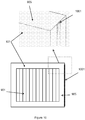
- Figure 12 is a schematic plan view of a panel 101 in a closed position, showing how a galvanized steel plate 1001 attached to the free-swinging vertical side 107 of a noise barrier panel 101 is located into a U-shaped aluminium trough 1101 of an adjacent noise barrier panel 101.
- Figure 10 also shows the free-swinging vertical side 107 of the noise barrier panel 101 installed with the galvanized steel plate 1001.
- FIG 13 shows in greater detail how the galvanized steel plate 1001 fits into U-shaped aluminium trough 1101 of the adjacent noise barrier panel 101.
- the sleeve 105 is illustrated in Figure 13 with a mounting pole 102 extending through it.
- the galvanized steel plate 1001 In the closed position of a noise barrier panel 101, the galvanized steel plate 1001 is dimensioned to fit loosely into the U-shaped aluminium trough 1101 of an adjacent noise barrier panel 101, which provides a simple recessed locking mechanism between the two panels.
- the galvanized steel plate 1001 also provides magnetic cooperation with magnets in the sleeve 105 with of the adjacent noise barrier panel 101, which improves the strength of the recessed locking mechanism.
- the wind load threshold of the noise barrier panel 101 can be determined by how much the galvanized steel plate 1001 extends into the U-shaped aluminium trough 1101 and by changing the number, size and type of magnets installed in the U-shaped aluminium trough 1101.
- the magnets are attached to the free-swinging vertical side 107 of the noise barrier panel 101 and a ferromagnetic material such as galvanised steel is placed in the U-shaped aluminium trough 1101.
- magnets are attached both to in the U-shaped aluminium trough 1101 and at the free-swinging vertical side 107.
- the strengths of the locking mechanisms and the magnetic cooperation between all the noise barrier panels 101 are the same. Every noise barrier panel 101 has the same wind load threshold.
- different noise barrier panels 101 are provided with different strengths of locking mechanism and magnetic cooperation with the sleeve 105 of the adjacent noise barrier panel 101; different noise barrier panels 101 are tuned to different wind load thresholds.
- the noise barrier panels 101 at the top of the mounting poles 102 can have the lowest threshold in order to limit the wind load at the upper end of the mounting poles 102, and the threshold of the noise barrier panels 101 lower on the mounting poles 102 is greater.
- a noise barrier panel 101 in the open position can be closed using a rod to push the noise barrier panel 101 back towards the closed position, and the magnetic attraction between the free-swinging vertical side 107 of a noise barrier panel 101 and the sleeve 105 of the adjacent noise barrier panel 101 will attract the noise barrier panel 101 back into the closed position.
- a resilient device such as a weak spring can be used to urge each noise barrier panel 101 into the closed position. The spring has to be weak enough not to interfere with the threshold level of wind load at which the noise barrier panel 101 should open.
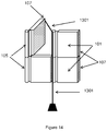
- each noise barrier panel 101 can be tied to a string which is threaded to a pulley system 1301 loaded with a weight threading through the adjacent mounting pole 102.
- Figure 15 is a zoomed out illustration of the noise barrier panel 101.
- the noise barrier panels 101 on the same mounting pole 102 can be locked together, so that the column of noise barrier panels 101 behaves like one large panel.
- the operator need only push the lowest noise barrier panel 101 back into the closed position.
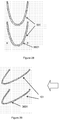
- Figure 16 is the cross-sectional plan view of the preferred configuration of the cushion 901, which comprises segmented gas-inflated tubes 903.
- Figure 17 shows a variation of the cushion 901 of Figure 16 , wherein the gas-inflated tubes 903 are each partially filled with a liquid 1501.
- the liquid can be water or other commonly used liquid which is available at low cost without hazard concerns.
- the liquid is a viscous liquid or a mixture of volatile and viscous substances to increase the contact area of the liquid with the inner surfaces of the segmented gas-inflated tubes 903. More preferably, however, the liquid is a volatile one which is capable of absorbing sound energy by evaporation and releasing heat on condensation. Sound energy can also be dissipated by the viscous damping through hysteresis.
- Figure 17 also shows droplets 1503 of volatile liquid adhering to the internal surface of the segmented gas-inflated tubes 903 further enhance sound absorption.
- Figure 18 is another plan view of the cushion 901 showing sound insulation or absorption layers 1601 covering or enveloping the main surface of the cushion 901.
- the sound insulation or absorption layers can be woven fabric material, plastic sheets, and corrugated cardboards and so on.
- Figure 19 is another plan view of the cushion 901 showing a constrained-layer damping design, which comprises gas-inflated tubes with double walls. Between the double walls 1701 of each gas-inflated tube is a viscous liquid or visco-elastic material. Vibration motion of the gas-inflated tubes forces a relative displacement of the liquid or visco-elastic material within the double walls 1701 to absorb sound energy; sound energy is effectively absorbed by the large contact area between the visco-elastic material and the internal walls of the double layer gas-inflated tubes.
- the described noise barrier 100 possibly provide sound insulation performance similar to a conventional noise barrier, at up to Noise Isolation Class 30 and providing more than 35dB(A) reduction of white noise.
- Figure 20 show a second embodiment which is a noise barrier 100.
- the noise barrier 100 has two main parts, namely, flexible noise barrier panels 101 and a frame 103 for mounting the noise barrier panels 101 thereon.
- the frame 103 provides standing support for noise barrier panels 101 and is made up of a pair of mounting poles 102 erected vertically on the ground.
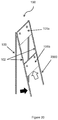
- the frame 103 is provided with a rail system 2000 for installation of noise barrier panels 101.
- the rail system 2000 is pivoted to the top of each mounting pole 102.
- Each rail 2000 is almost as long as the mounting pole 102.
- the black block arrow in Figure 20 also illustrates how the lower end of the rail system 2000 can be pulled away from the leg of the mounting pole 102, so that the rail system 2000 is slanted at an angle to the frame 103.
- Figure 21 shows a noise barrier panel 101 for insertion into the rail system 2000.
- the noise barrier panel 101 provides a large surface area 1901 for insulating sound.
- the top side of the noise barrier panel 101 is attached to a mounting tube 1903.
- the mounting tube 1903 has two ends 1905, each of which extending over the respective lateral side of the noise barrier panel 101 for engaging the rail system 2000.
- the entire noise barrier panel 101 can be slid in the rail system 2000.
- the material used for the noise barrier panel 101 is either sound absorbing or sound blocking, and is light weight.
- dividers such as rods (not shown), i.e. between points A to A and between points B to B as labelled in Figure 20 .
- the dividers ensure that the top panel 101a is kept above the lower panel 101b at a pre-determined height.
- the ends 1905 of the mounting tube 1903 of the lower panel 101b push on the dividers, which in turn push on the ends 1905 of the mounting tube 1903 of the top panel 101a. This allows the panels to be installed at ground level and then slid up, as indicated by the white arrow in Figure 20 .
- the bottom edge of a top noise barrier panel 101 preferably overlaps, or is aligned closely to the top edge of a bottom noise barrier panel 101.
- Figure 22 illustrates shows that the rail system 2000 comprises a U-shaped guide like a curtain rail.
- Figure 23 shows how the rails 2000 are pushed back to lie against the frame 103 after the noise barrier panels 101 have been inserted into the rails 2000.
- the structure as shown is a modular design, and two or more different independent frames 103 can be assembled side by side on site to extend a noise barrier 100 laterally.
- the shape-changing mechanism is provided by the material used for the body of the noise barrier panel 101.
- the material can be any which is flexible and bend-able to allow wind passage, and resilient enough to revert to the original position under normal wind condition.
- the body of the noise barrier panel 101 comprises a cushion 901 made of segmented gas inflated tubes 903, such as the one discussed in Figure 9 .
- the gas-inflated tubes are stiff enough in their axial direction to provide an upstanding panel with minimal support.
- noise barrier 100 Since wind load on the noise barrier 100 is limited by a shape-changing mechanism, noise barrier 100 does not need to be made of heavy material or a concrete foundation, and can be made of light material which is easy for manual installation.
- Figure 24 shows a variation of the embodiment, which is a frame 103 installed with three noise barrier panels 101.
- the top noise barrier panel 101e has a different design to that of the two lower noise barrier panels 101f.
- the mounting tube 1903 of each of the two lower noise barrier panels 101f is placed at the top side of the respective noise barrier panel 101f, that is, the noise barrier panel 101f hangs down from the mounting tube 1903.
- the mounting tube 1903 of the top noise barrier panel 101e is placed across the middle of the noise barrier panel 101e, and all four sides of the noise barrier panel 101e are not affixed to any mounting tube 1903.
- the noise barrier panels 101 are illustrated as flapping open in the presence of wind. The wind direction is indicated by the block arrow.
- top noise barrier panel 101e folds around the mounting tube 1903 to bend; both the top and the bottom edges of the top noise barrier panel 101e are moved according to the direction of the wind.
- the lower two noise barrier panels 101f simply fold and swivel about the mounting tube 1903 at their top edges.
- the resilience in the noise barrier panel 101 material returns the noise barrier panel 101 into its original configuration automatically, to resume function as noise barrier.
- wind loading on the noise barrier is limited by the threshold wind load at which the noise barrier panels 101 open. It is estimated that the wind load on the fully open noise barrier is only one-tenth of the barrier without opening, at between 0.02 to 0.3kPa, which is only 2% to 25% of the conventional outdoor noise barrier loading requirement of about 1.2kPa.
- the light material provides that the noise barrier is so easy to erect and dismantle, without using cranes or elevated platforms, that it is suitable for temporal, short period use.
- the noise barrier panels of this embodiment are small and lightweight with a preferable size of less than 5m 2 and surface density less than 2kg/m 2 .
- the edges of a noise barrier panel 101 are provided with magnetic material to act as magnetic locks.
- the magnetic material in the lateral edges of the noise barrier panel 101 is attracted to corresponding magnetic material in the vertical mounting poles 102.
- determining the threshold wind load has to take into account the strength of the magnetic attraction between the free edges of the noise barrier panel 101 and the mounting poles 102.
- Figure 25 and Figure 26 shows a variation of the embodiment, wherein all the noise barrier panels 101 are each sandwiched between two mid-section mounting tubes 1903, so that wind may blow in any direction and the panel 101 can bend according to that the wind direction on either side of the noise barrier 100.
- the described noise barrier panels 101 do not require a pivoting mechanism to flap open in the wind, as they are capable of deforming in wind. However, if the noise barrier panel 101 is made of a rigid and unbendable material in embodiments not falling under the scope of the present invention, the noise barrier panel 101 is secured to the frame by a pivoting mechanism.
- the mounting tubes 1905 can be mounted on the railing to be able to turn pivotally.
- Figure 27 shows a further embodiment, which is noise barrier 100 comprising an array of noise barrier panels 101.
- the noise barrier panels 101 are made of hanging fabric such as woven curtain, or flexible plastic sheets.
- the noise barrier panels 101 are arranged to form several parallel noise barrier walls facing a construction site. These are crossed orthogonally by yet several other noise barrier walls facing the side. When there is wind, the panels are blown apart to opens up a wind passage. The higher the number of parallel noise barrier walls, the higher the wind load threshold.
- the panels facing sideway help to prevent small displacements of the panels facing the front during very mild wind condition, to maintain noise barrier function.
- Figure 28 shows another embodiment in which the noise barrier panel 101 can be a piece of flexible material, the ends of which are hanging from two horizontal supports to form a sort of U-shaped or V-shaped hanging curtain 101 having a bottom apex 3601.
- the bottom apex 3601 of the hanging curtain 101 can be inserted slightly between the two opposite ends of a similar hanging curtain immediately below.
- the overlap of the lower apex 3601 of an upper curtain and the two ends of a lower curtain forms a vertically continual wall for blocking noise.
- Figure 29 shows how the loose hanging curtain can be blown by wind in the direction of the block arrow to allow wind passage.
- the threshold for opening the curtains depends on the weight of the material used for the curtains. The heavier the weight, the stronger the wind to blow a curtain aside.
- the apex 3601 can be provided with holes to prevent collection of rain water.
- a noise barrier 100 comprising at least one noise barrier panel 101 which is capable of being moved by the force of wind to allow passage of wind.
- the noise barrier 100 comprises at least one noise barrier panel 101, the at least one noise barrier panel 101 having a close position for providing barrier to noise, the at least one noise barrier panel 101 having an open position to allow passage of wind, wherein the at least one noise barrier panel 101 is capable of being folded by the force of wind from the closed to the open position.
- the noise barrier panel 101 opens by folding relative to a vertical axis or a horizontal axis.
- a noise barrier 100 has also been described comprising at least one mounting pole, 102 at least one noise barrier panel 101 mounted on the at least one mounting pole 102 to be slide-able on the mounting pole 102.
- the noise barrier 100 can be set up by an operating company, or if the user prefers, the user can order a noise barrier kit, comprising at least one mounting pole, at least one noise barrier panel suitable for mounting onto the at least one mounting pole to be slide-able along the mounting pole. The user can set up the noise barrier himself at any time convenient for him without requiring any heavy machinery.
- the mounting pole 102 is foldable or retractable.
Landscapes
- Engineering & Computer Science (AREA)
- Architecture (AREA)
- Civil Engineering (AREA)
- Structural Engineering (AREA)
- Physics & Mathematics (AREA)
- Acoustics & Sound (AREA)
- Electromagnetism (AREA)
- Devices Affording Protection Of Roads Or Walls For Sound Insulation (AREA)
- Building Environments (AREA)
Claims (12)
- Schallschutzwand (100) aufweisend:mindestens zwei einen Rahmen (103) bildendeBefestigungsstangen (102), mindestens ein über besagtem Rahmen (103) platziertes Schallschutzwandelement (101), das geeignet ist, durch Windkraft bewegt zu werden, um Wind passieren zu lassen; das mindestens eine Schallschutzwandelement (101) hat eine geschlossene Stellung zum Erzeugen von Schallschutz; und das mindestens eine Schallschutzwandelement (101) hat eine offene Stellung um Wind passieren zu lassen; das mindestens eine Schallschutzwandelement (101) ist geeignet, durch Windkraft aus der geschlossenen Stellung in die offene Stellung bewegt zu werden; dadurch gekennzeichnet, dass das mindestens eine Schallschutzwandelement (101) geeignet ist, sich durch Zusammenfalten von einer geschlossenen in eine offene Stellung zu bewegen.
- Schallschutzwand (100) nach Anspruch 1, dadurch gekennzeichnet, dass das mindestens eine Schallschutzwandelement (101) magnetisches Material aufweist, um das mindestens eine Schallschutzwandelement (101) in der geschlossenen Stellung zu halten.
- Schallschutzwand (100) nach Anspruch 2, dadurch gekennzeichnet, dass das mindestens eine Schallschutzwandelement (101) eine erste Seite mit einem ersten magnetischen Material hat; das mindestens eine Schallschutzwandelement (101) eine zweite Seite mit einem zweiten magnetischen Material hat; das zweite magnetische Material der zweiten Seite des mindestens einen Schallschutzwandelements (101) geeignet ist, mit dem ersten magnetischen Material der ersten Seite eines angrenzenden Schallschutzwandelements (101) magnetisch zusammenzuwirken.
- Schallschutzwand (100) nach einem der vorhergehenden Ansprüche, dadurch gekennzeichnet, dass das mindestens eine Schallschutzwandelement (101) ein aufblasbares Polster aufweist.
- Schallschutzwand (100) nach Anspruch 4, dadurch gekennzeichnet, dass das aufblasbare Polster eine Vielzahl aufblasbarer Abschnitte aufweist.
- Schallschutzwand (100) nach Anspruch 4 oder 5, dadurch gekennzeichnet, dass das aufblasbare Polster eine zum Absorbieren von Schallenergie geeignete Flüssigkeit beinhaltet.
- Schallschutzwand (100) nach einem der vorhergehenden Ansprüche, dadurch gekennzeichnet, dass das mindestens eine Schallschutzwandelement (101) geeignet ist an einer der Befestigungsstangen (102) befestigt zu werden, um entlang der Befestigungsstange (102) verschiebbar zu sein.
- Schallschutzwandelement (101) zur Verwendung in der Schallschutzwand nach einem der Ansprüche 1 bis 7, aufweisend ein zum Befestigen an einer Befestigungsstange (102) geeignetes aufblasbares Polster, so dass das befestigte Schallschutzwandelement (101) geeignet ist durch Windkraft bewegt zu werden, um Wind passieren zu lassen; das mindestens eine Schallschatzwandelement (101), im befestigten Zustand, eine geschlossene Stellung zum Erzeugen von Schallschutz hat; das mindestens eine Schallschatzwandelement (101), im befestigten Zustand, eine offene Position hat, um Wind passieren zu lassen; das mindestens eine Schallschatzwandelement (101), im befestigten Zustand, geeignet ist durch Windkraft von einer geschlossenen Stellung in eine offene Stellung bewegt zu werden; wobei das Schallschutzwandelement (101) im befestigten Zustand geeignet ist, sich durch Zusammenfalten von einer geschlossenen in eine offene Stellung zu bewegen, wobei das Schallschutzwandelement (101) zusätzlich eine erste Seite mit einem ersten magnetischen Material aufweist; und eine zweite Seite mit einem zweiten magnetischen Material; das zweite magnetische Material der zweiten Seite des Schallschatzwandelements geeignet ist, mit einem ersten magnetischen Material der ersten Seite eines angrenzenden Schallschutzwandelements magnetisch zusammenzuwirken.
- Schallschutzwandelement (101) nach Anspruch 8, dadurch gekennzeichnet, dass das aufblasbares Polster eine Vielzahl an aufblasbaren Abschnitten (903) aufweist.
- Schallschutzwandelement (101) nach Anspruch 8 oder 9, dadurch gekennzeichnet, dass das Schallschutzelement (101) zusätzlich eine Hülse (105) für das Befestigen an einer der Befestigungsstangen (102) aufweist.
- Verfahren zur Installierung der Schallschutzwand (100) nach einem der Ansprüche 1 bis 7 aufweisend:Bereitstellen von mindestens zwei Befestigungsstangen (102); Bereitstellen eines ersten Schallschutzwandelements (101);Befestigen des ersten Schallschutzwandelements (101) an mindestens einer der Befestigungsstangen (102); Verschieben des ersten Schallschutzwandelements (101) entlang der mindestens einen Befestigungsstange (102).
- Verfahren zur Installierung einer Schallschutzwand (100) nach Anspruch 11, aufweisend:Bereitstellen eines zweiten Schallschutzwandelements (101);Befestigen des zweiten Schallschutzwandelements (101) an mindestens einer der Befestigungsstangen (102); Verschieben des zweiten Schallschutzwandelements (101) entlang der mindestens einen Befestigungsstange (102), um das erste Schallschutzwandelement (101) entlang der mindestens einen Befestigungsstange (102) zu schieben.
Applications Claiming Priority (3)
| Application Number | Priority Date | Filing Date | Title |
|---|---|---|---|
| US201361811137P | 2013-04-12 | 2013-04-12 | |
| US201461931693P | 2014-01-27 | 2014-01-27 | |
| PCT/CN2014/075173 WO2014166422A1 (en) | 2013-04-12 | 2014-04-11 | A noise barrier and a method of costruction thereof |
Publications (3)
| Publication Number | Publication Date |
|---|---|
| EP2956586A1 EP2956586A1 (de) | 2015-12-23 |
| EP2956586A4 EP2956586A4 (de) | 2016-11-02 |
| EP2956586B1 true EP2956586B1 (de) | 2018-03-07 |
Family
ID=51688946
Family Applications (1)
| Application Number | Title | Priority Date | Filing Date |
|---|---|---|---|
| EP14782785.1A Active EP2956586B1 (de) | 2013-04-12 | 2014-04-11 | Lärmschutzwand und konstruktionsverfahren dafür |
Country Status (8)
| Country | Link |
|---|---|
| US (1) | US9366025B2 (de) |
| EP (1) | EP2956586B1 (de) |
| CN (1) | CN104968861A (de) |
| AU (1) | AU2014252535B2 (de) |
| HK (1) | HK1215059A1 (de) |
| NZ (1) | NZ713217A (de) |
| SG (1) | SG11201508012VA (de) |
| WO (1) | WO2014166422A1 (de) |
Cited By (1)
| Publication number | Priority date | Publication date | Assignee | Title |
|---|---|---|---|---|
| CN108316174A (zh) * | 2018-03-23 | 2018-07-24 | 中国铁路郑州局集团有限公司科学技术研究所 | 声屏障检修设备及方法 |
Families Citing this family (23)
| Publication number | Priority date | Publication date | Assignee | Title |
|---|---|---|---|---|
| HK1217151A2 (zh) * | 2015-06-15 | 2016-12-23 | 何伟麟 | 轻便式工地噪声屏 |
| JP7321490B2 (ja) | 2016-02-10 | 2023-08-07 | グレー ピラー ジェームズ | 強化された膨張可能な音波減衰システム |
| CN106193793B (zh) * | 2016-06-25 | 2018-09-18 | 甘肃建筑职业技术学院 | 一种建筑施工用的隔离围栏 |
| CN107829600B (zh) * | 2016-06-28 | 2019-05-10 | 衢州市易凡设计有限公司 | 一种有纱网的墙上围栏防风沙的方法 |
| CN108661420A (zh) * | 2016-06-28 | 2018-10-16 | 蒋爱君 | 一种电磁复位加固型有纱网的围栏 |
| CN105909055B (zh) * | 2016-06-28 | 2018-07-20 | 衢州市优德工业设计有限公司 | 一种加固型围栏 |
| CN108643691A (zh) * | 2016-06-28 | 2018-10-12 | 蒋爱君 | 一种墙上可调节有纱网的围栏 |
| CN108612399A (zh) * | 2016-06-28 | 2018-10-02 | 蒋爱君 | 一种可调节的围栏防风沙的方法 |
| CN106121361B (zh) * | 2016-06-28 | 2018-07-03 | 衢州市优德工业设计有限公司 | 一种围栏 |
| CN106049983B (zh) * | 2016-06-28 | 2018-08-28 | 衢州市优德工业设计有限公司 | 一种采用加固型围栏防风沙的方法 |
| CN108643694A (zh) * | 2016-06-28 | 2018-10-12 | 蒋爱君 | 一种电磁式可调有纱网加固型围栏防风沙方法 |
| DK179483B1 (en) * | 2017-03-05 | 2018-12-17 | Werner Adelmann-Larsen Niels | Variable Acoustic Technology for Rooms |
| CN107034799B (zh) * | 2017-05-26 | 2023-05-16 | 华东交通大学 | 一种感应式升降声屏障系统及其工作方法 |
| JP6997596B2 (ja) * | 2017-11-09 | 2022-01-17 | 三菱重工コンプレッサ株式会社 | 防音制御システム、防音制御装置、防音制御方法、プログラム |
| CN109371863B (zh) * | 2018-11-09 | 2024-01-26 | 山东大学 | 一种双侧受风减载环保声屏障 |
| CN109518833B (zh) * | 2018-11-22 | 2021-06-25 | 安徽工程大学 | 一种舞台反声罩 |
| CN109853409B (zh) * | 2019-01-12 | 2021-04-09 | 温州中泽建筑装饰有限公司 | 一种隔音墙 |
| US11535991B2 (en) * | 2019-02-14 | 2022-12-27 | Mark Adam Tryon | Noise attenuating barrier and method of installing same |
| CN109914911B (zh) * | 2019-03-22 | 2023-11-10 | 张家港固耐特体育智能科技有限公司 | 一种围栏增强器及围栏增强方法 |
| CN111255110B (zh) * | 2020-03-10 | 2021-04-13 | 东莞瑞森新谱声学科技有限公司 | 一种自动控制抽屉式可调吸声系统及其控制方法 |
| CN113863524A (zh) * | 2021-10-25 | 2021-12-31 | 中科深兰(福建)环境科技有限责任公司 | 一种噪声处理用可调节的双层隔离板及其使用方法 |
| CN114808778B (zh) * | 2022-03-08 | 2023-07-14 | 中铁第四勘察设计院集团有限公司 | 一种利用太阳能发电且具有防护功能的声屏障 |
| CN116657520B (zh) * | 2023-06-16 | 2025-09-19 | 安徽尚德科技有限公司 | 一种铁路桥梁风屏障 |
Family Cites Families (18)
| Publication number | Priority date | Publication date | Assignee | Title |
|---|---|---|---|---|
| US3307809A (en) * | 1965-06-01 | 1967-03-07 | Lynn Bernard Stanley | Convexly curved deflector for elevated jet engines blasts |
| US3473786A (en) * | 1967-06-30 | 1969-10-21 | Robert W Luebke | Fencing for controlling accumulation and drifting of snow,sand or other heavier-than-air particles suspended in air currents |
| DE2614568A1 (de) * | 1976-04-05 | 1977-10-13 | Norbert Colberg | Laerm- und blendschutzwand |
| US4671495A (en) * | 1986-04-07 | 1987-06-09 | Margaret G. Garland | Particulate material control apparatus |
| GB2241000B (en) * | 1990-02-14 | 1993-11-17 | John Baker | Fencing |
| CN2260159Y (zh) * | 1996-05-28 | 1997-08-20 | 粟海 | 多功能折叠防盗门 |
| US6085861A (en) * | 1998-10-08 | 2000-07-11 | Wenger Corporation | Collapsible portable acoustic tower |
| CN2748500Y (zh) * | 2004-11-24 | 2005-12-28 | 东莞联华五金制品有限公司 | 一种吸音隔音板 |
| CN1332096C (zh) * | 2005-01-20 | 2007-08-15 | 上海交通大学 | 双面吸声啮合空腔无棉声屏障 |
| US7992678B2 (en) * | 2005-05-12 | 2011-08-09 | Pilaar James G | Inflatable sound attenuation system |
| US7857291B2 (en) * | 2005-06-02 | 2010-12-28 | Dombroski Edward L | Flexible fence assembly |
| CN2895514Y (zh) | 2005-08-26 | 2007-05-02 | 任建章 | 多层透明旋转窗扇式隔音墙 |
| CN2886006Y (zh) | 2005-11-22 | 2007-04-04 | 高义禄 | 一种可调整迎风面积之围篱结构 |
| US7921960B2 (en) * | 2006-07-26 | 2011-04-12 | Wenger Corporation | Acoustic cabinet |
| CN201080751Y (zh) * | 2007-08-15 | 2008-07-02 | 单悌富 | 一种磁吸门 |
| US7793886B2 (en) * | 2009-01-14 | 2010-09-14 | Henson Iii George A | Jet air recovery generator and jet blast deflector |
| CN202055618U (zh) * | 2011-04-22 | 2011-11-30 | 有利华建筑预制件有限公司 | 建筑工地的降噪减尘隔墙系统 |
| WO2013049814A1 (en) * | 2011-09-30 | 2013-04-04 | Zimmerman Donald Robert | Noise barrier |
-
2014
- 2014-04-11 CN CN201480003479.2A patent/CN104968861A/zh active Pending
- 2014-04-11 US US14/432,413 patent/US9366025B2/en active Active
- 2014-04-11 EP EP14782785.1A patent/EP2956586B1/de active Active
- 2014-04-11 SG SG11201508012VA patent/SG11201508012VA/en unknown
- 2014-04-11 HK HK16103023.7A patent/HK1215059A1/zh unknown
- 2014-04-11 WO PCT/CN2014/075173 patent/WO2014166422A1/en not_active Ceased
- 2014-04-11 NZ NZ713217A patent/NZ713217A/en unknown
- 2014-04-11 AU AU2014252535A patent/AU2014252535B2/en active Active
Non-Patent Citations (1)
| Title |
|---|
| None * |
Cited By (2)
| Publication number | Priority date | Publication date | Assignee | Title |
|---|---|---|---|---|
| CN108316174A (zh) * | 2018-03-23 | 2018-07-24 | 中国铁路郑州局集团有限公司科学技术研究所 | 声屏障检修设备及方法 |
| CN108316174B (zh) * | 2018-03-23 | 2023-08-25 | 中国铁路郑州局集团有限公司科学技术研究所 | 声屏障检修设备及方法 |
Also Published As
| Publication number | Publication date |
|---|---|
| HK1215059A1 (zh) | 2016-08-12 |
| CN104968861A (zh) | 2015-10-07 |
| EP2956586A4 (de) | 2016-11-02 |
| SG11201508012VA (en) | 2015-10-29 |
| US20150267403A1 (en) | 2015-09-24 |
| NZ713217A (en) | 2016-12-23 |
| US9366025B2 (en) | 2016-06-14 |
| AU2014252535A1 (en) | 2015-10-22 |
| WO2014166422A1 (en) | 2014-10-16 |
| EP2956586A1 (de) | 2015-12-23 |
| AU2014252535B2 (en) | 2017-04-13 |
Similar Documents
| Publication | Publication Date | Title |
|---|---|---|
| EP2956586B1 (de) | Lärmschutzwand und konstruktionsverfahren dafür | |
| US8851095B2 (en) | Pole mounted cooler | |
| US20070228349A1 (en) | Portable privacy fence incorporating ground secured posts, each including a mesh unwinding section and a succeeding supporting section | |
| US20160143453A1 (en) | Disassemblable and Carryable Beach/Park Corral | |
| US6840254B1 (en) | Portable dressing blind and method of use | |
| US20160290002A1 (en) | Shelter deployment handles | |
| US10286273B1 (en) | Shallow water volleyball net anchoring system | |
| JP5150611B2 (ja) | 仮設構造物 | |
| US20170030083A1 (en) | Privacy and weather protection barrier | |
| KR102276958B1 (ko) | 부상(浮上) 방지기능이 강화된 막구조물 | |
| CN109106264A (zh) | 一种便携式户外厕所及其安装方法 | |
| GB2543875A (en) | Light weight construction site retractable noise barrier | |
| US3779259A (en) | Collapsible protective structure | |
| CN209547866U (zh) | 一种便携式户外厕所 | |
| JP2623072B2 (ja) | ドーム型仮設テントとその組立方法 | |
| CN116290858A (zh) | 一种可提高二次使用率的新型施工区防护墙 | |
| CN211818192U (zh) | 一种房建施工用伸缩式安全防坠装置 | |
| KR20100111450A (ko) | 휴대용 조립식 그늘막 | |
| CN223880878U (zh) | 一种施工围挡单元及施工围挡 | |
| CN220014693U (zh) | 一种组合式抗风墙板及抗风墙体 | |
| CN218092433U (zh) | 一种自主收回型围栏 | |
| CN216617108U (zh) | 一种钢结构工程施工用防护装置 | |
| KR102946300B1 (ko) | 경사기둥과 무게추를 이용한 웨이브 어닝용 설치 구조물 | |
| KR200200438Y1 (ko) | 이동식 방음장치 | |
| KR101726217B1 (ko) | 트러스 구조의 일측 변을 천막 부재로 대체한 천막 |
Legal Events
| Date | Code | Title | Description |
|---|---|---|---|
| PUAI | Public reference made under article 153(3) epc to a published international application that has entered the european phase |
Free format text: ORIGINAL CODE: 0009012 |
|
| 17P | Request for examination filed |
Effective date: 20150422 |
|
| AK | Designated contracting states |
Kind code of ref document: A1 Designated state(s): AL AT BE BG CH CY CZ DE DK EE ES FI FR GB GR HR HU IE IS IT LI LT LU LV MC MK MT NL NO PL PT RO RS SE SI SK SM TR |
|
| AX | Request for extension of the european patent |
Extension state: BA ME |
|
| DAX | Request for extension of the european patent (deleted) | ||
| A4 | Supplementary search report drawn up and despatched |
Effective date: 20160930 |
|
| RIC1 | Information provided on ipc code assigned before grant |
Ipc: E04H 17/14 20060101ALI20160926BHEP Ipc: E01F 8/00 20060101AFI20160926BHEP |
|
| RAP1 | Party data changed (applicant data changed or rights of an application transferred) |
Owner name: ACOUSTICS INNOVATION LTD. |
|
| GRAP | Despatch of communication of intention to grant a patent |
Free format text: ORIGINAL CODE: EPIDOSNIGR1 |
|
| INTG | Intention to grant announced |
Effective date: 20171002 |
|
| RAP1 | Party data changed (applicant data changed or rights of an application transferred) |
Owner name: ACOUSTICS INNOVATION LTD. |
|
| GRAS | Grant fee paid |
Free format text: ORIGINAL CODE: EPIDOSNIGR3 |
|
| GRAA | (expected) grant |
Free format text: ORIGINAL CODE: 0009210 |
|
| AK | Designated contracting states |
Kind code of ref document: B1 Designated state(s): AL AT BE BG CH CY CZ DE DK EE ES FI FR GB GR HR HU IE IS IT LI LT LU LV MC MK MT NL NO PL PT RO RS SE SI SK SM TR |
|
| REG | Reference to a national code |
Ref country code: GB Ref legal event code: FG4D |
|
| REG | Reference to a national code |
Ref country code: CH Ref legal event code: EP Ref country code: AT Ref legal event code: REF Ref document number: 976694 Country of ref document: AT Kind code of ref document: T Effective date: 20180315 |
|
| REG | Reference to a national code |
Ref country code: DE Ref legal event code: R096 Ref document number: 602014022103 Country of ref document: DE |
|
| REG | Reference to a national code |
Ref country code: IE Ref legal event code: FG4D |
|
| REG | Reference to a national code |
Ref country code: NL Ref legal event code: MP Effective date: 20180307 |
|
| REG | Reference to a national code |
Ref country code: LT Ref legal event code: MG4D |
|
| PG25 | Lapsed in a contracting state [announced via postgrant information from national office to epo] |
Ref country code: HR Free format text: LAPSE BECAUSE OF FAILURE TO SUBMIT A TRANSLATION OF THE DESCRIPTION OR TO PAY THE FEE WITHIN THE PRESCRIBED TIME-LIMIT Effective date: 20180307 Ref country code: FI Free format text: LAPSE BECAUSE OF FAILURE TO SUBMIT A TRANSLATION OF THE DESCRIPTION OR TO PAY THE FEE WITHIN THE PRESCRIBED TIME-LIMIT Effective date: 20180307 Ref country code: LT Free format text: LAPSE BECAUSE OF FAILURE TO SUBMIT A TRANSLATION OF THE DESCRIPTION OR TO PAY THE FEE WITHIN THE PRESCRIBED TIME-LIMIT Effective date: 20180307 Ref country code: NO Free format text: LAPSE BECAUSE OF FAILURE TO SUBMIT A TRANSLATION OF THE DESCRIPTION OR TO PAY THE FEE WITHIN THE PRESCRIBED TIME-LIMIT Effective date: 20180607 Ref country code: ES Free format text: LAPSE BECAUSE OF FAILURE TO SUBMIT A TRANSLATION OF THE DESCRIPTION OR TO PAY THE FEE WITHIN THE PRESCRIBED TIME-LIMIT Effective date: 20180307 Ref country code: CY Free format text: LAPSE BECAUSE OF FAILURE TO SUBMIT A TRANSLATION OF THE DESCRIPTION OR TO PAY THE FEE WITHIN THE PRESCRIBED TIME-LIMIT Effective date: 20180307 |
|
| REG | Reference to a national code |
Ref country code: AT Ref legal event code: MK05 Ref document number: 976694 Country of ref document: AT Kind code of ref document: T Effective date: 20180307 |
|
| PG25 | Lapsed in a contracting state [announced via postgrant information from national office to epo] |
Ref country code: RS Free format text: LAPSE BECAUSE OF FAILURE TO SUBMIT A TRANSLATION OF THE DESCRIPTION OR TO PAY THE FEE WITHIN THE PRESCRIBED TIME-LIMIT Effective date: 20180307 Ref country code: GR Free format text: LAPSE BECAUSE OF FAILURE TO SUBMIT A TRANSLATION OF THE DESCRIPTION OR TO PAY THE FEE WITHIN THE PRESCRIBED TIME-LIMIT Effective date: 20180608 Ref country code: LV Free format text: LAPSE BECAUSE OF FAILURE TO SUBMIT A TRANSLATION OF THE DESCRIPTION OR TO PAY THE FEE WITHIN THE PRESCRIBED TIME-LIMIT Effective date: 20180307 Ref country code: SE Free format text: LAPSE BECAUSE OF FAILURE TO SUBMIT A TRANSLATION OF THE DESCRIPTION OR TO PAY THE FEE WITHIN THE PRESCRIBED TIME-LIMIT Effective date: 20180307 Ref country code: BG Free format text: LAPSE BECAUSE OF FAILURE TO SUBMIT A TRANSLATION OF THE DESCRIPTION OR TO PAY THE FEE WITHIN THE PRESCRIBED TIME-LIMIT Effective date: 20180607 |
|
| PG25 | Lapsed in a contracting state [announced via postgrant information from national office to epo] |
Ref country code: AL Free format text: LAPSE BECAUSE OF FAILURE TO SUBMIT A TRANSLATION OF THE DESCRIPTION OR TO PAY THE FEE WITHIN THE PRESCRIBED TIME-LIMIT Effective date: 20180307 Ref country code: EE Free format text: LAPSE BECAUSE OF FAILURE TO SUBMIT A TRANSLATION OF THE DESCRIPTION OR TO PAY THE FEE WITHIN THE PRESCRIBED TIME-LIMIT Effective date: 20180307 Ref country code: IT Free format text: LAPSE BECAUSE OF FAILURE TO SUBMIT A TRANSLATION OF THE DESCRIPTION OR TO PAY THE FEE WITHIN THE PRESCRIBED TIME-LIMIT Effective date: 20180307 Ref country code: RO Free format text: LAPSE BECAUSE OF FAILURE TO SUBMIT A TRANSLATION OF THE DESCRIPTION OR TO PAY THE FEE WITHIN THE PRESCRIBED TIME-LIMIT Effective date: 20180307 Ref country code: NL Free format text: LAPSE BECAUSE OF FAILURE TO SUBMIT A TRANSLATION OF THE DESCRIPTION OR TO PAY THE FEE WITHIN THE PRESCRIBED TIME-LIMIT Effective date: 20180307 Ref country code: PL Free format text: LAPSE BECAUSE OF FAILURE TO SUBMIT A TRANSLATION OF THE DESCRIPTION OR TO PAY THE FEE WITHIN THE PRESCRIBED TIME-LIMIT Effective date: 20180307 |
|
| REG | Reference to a national code |
Ref country code: DE Ref legal event code: R119 Ref document number: 602014022103 Country of ref document: DE |
|
| PG25 | Lapsed in a contracting state [announced via postgrant information from national office to epo] |
Ref country code: CZ Free format text: LAPSE BECAUSE OF FAILURE TO SUBMIT A TRANSLATION OF THE DESCRIPTION OR TO PAY THE FEE WITHIN THE PRESCRIBED TIME-LIMIT Effective date: 20180307 Ref country code: SK Free format text: LAPSE BECAUSE OF FAILURE TO SUBMIT A TRANSLATION OF THE DESCRIPTION OR TO PAY THE FEE WITHIN THE PRESCRIBED TIME-LIMIT Effective date: 20180307 Ref country code: AT Free format text: LAPSE BECAUSE OF FAILURE TO SUBMIT A TRANSLATION OF THE DESCRIPTION OR TO PAY THE FEE WITHIN THE PRESCRIBED TIME-LIMIT Effective date: 20180307 Ref country code: SM Free format text: LAPSE BECAUSE OF FAILURE TO SUBMIT A TRANSLATION OF THE DESCRIPTION OR TO PAY THE FEE WITHIN THE PRESCRIBED TIME-LIMIT Effective date: 20180307 |
|
| REG | Reference to a national code |
Ref country code: CH Ref legal event code: PL |
|
| REG | Reference to a national code |
Ref country code: BE Ref legal event code: MM Effective date: 20180430 |
|
| PG25 | Lapsed in a contracting state [announced via postgrant information from national office to epo] |
Ref country code: PT Free format text: LAPSE BECAUSE OF FAILURE TO SUBMIT A TRANSLATION OF THE DESCRIPTION OR TO PAY THE FEE WITHIN THE PRESCRIBED TIME-LIMIT Effective date: 20180709 |
|
| PLBE | No opposition filed within time limit |
Free format text: ORIGINAL CODE: 0009261 |
|
| STAA | Information on the status of an ep patent application or granted ep patent |
Free format text: STATUS: NO OPPOSITION FILED WITHIN TIME LIMIT |
|
| REG | Reference to a national code |
Ref country code: IE Ref legal event code: MM4A |
|
| PG25 | Lapsed in a contracting state [announced via postgrant information from national office to epo] |
Ref country code: LU Free format text: LAPSE BECAUSE OF NON-PAYMENT OF DUE FEES Effective date: 20180411 Ref country code: DE Free format text: LAPSE BECAUSE OF NON-PAYMENT OF DUE FEES Effective date: 20181101 Ref country code: DK Free format text: LAPSE BECAUSE OF FAILURE TO SUBMIT A TRANSLATION OF THE DESCRIPTION OR TO PAY THE FEE WITHIN THE PRESCRIBED TIME-LIMIT Effective date: 20180307 Ref country code: MC Free format text: LAPSE BECAUSE OF FAILURE TO SUBMIT A TRANSLATION OF THE DESCRIPTION OR TO PAY THE FEE WITHIN THE PRESCRIBED TIME-LIMIT Effective date: 20180307 |
|
| 26N | No opposition filed |
Effective date: 20181210 |
|
| PG25 | Lapsed in a contracting state [announced via postgrant information from national office to epo] |
Ref country code: SI Free format text: LAPSE BECAUSE OF FAILURE TO SUBMIT A TRANSLATION OF THE DESCRIPTION OR TO PAY THE FEE WITHIN THE PRESCRIBED TIME-LIMIT Effective date: 20180307 Ref country code: LI Free format text: LAPSE BECAUSE OF NON-PAYMENT OF DUE FEES Effective date: 20180430 Ref country code: CH Free format text: LAPSE BECAUSE OF NON-PAYMENT OF DUE FEES Effective date: 20180430 Ref country code: BE Free format text: LAPSE BECAUSE OF NON-PAYMENT OF DUE FEES Effective date: 20180430 |
|
| PG25 | Lapsed in a contracting state [announced via postgrant information from national office to epo] |
Ref country code: FR Free format text: LAPSE BECAUSE OF NON-PAYMENT OF DUE FEES Effective date: 20180507 Ref country code: IE Free format text: LAPSE BECAUSE OF NON-PAYMENT OF DUE FEES Effective date: 20180411 |
|
| PG25 | Lapsed in a contracting state [announced via postgrant information from national office to epo] |
Ref country code: MT Free format text: LAPSE BECAUSE OF NON-PAYMENT OF DUE FEES Effective date: 20180411 |
|
| PG25 | Lapsed in a contracting state [announced via postgrant information from national office to epo] |
Ref country code: TR Free format text: LAPSE BECAUSE OF FAILURE TO SUBMIT A TRANSLATION OF THE DESCRIPTION OR TO PAY THE FEE WITHIN THE PRESCRIBED TIME-LIMIT Effective date: 20180307 |
|
| PG25 | Lapsed in a contracting state [announced via postgrant information from national office to epo] |
Ref country code: MK Free format text: LAPSE BECAUSE OF NON-PAYMENT OF DUE FEES Effective date: 20180307 Ref country code: HU Free format text: LAPSE BECAUSE OF FAILURE TO SUBMIT A TRANSLATION OF THE DESCRIPTION OR TO PAY THE FEE WITHIN THE PRESCRIBED TIME-LIMIT; INVALID AB INITIO Effective date: 20140411 |
|
| PG25 | Lapsed in a contracting state [announced via postgrant information from national office to epo] |
Ref country code: IS Free format text: LAPSE BECAUSE OF FAILURE TO SUBMIT A TRANSLATION OF THE DESCRIPTION OR TO PAY THE FEE WITHIN THE PRESCRIBED TIME-LIMIT Effective date: 20180707 |
|
| PGFP | Annual fee paid to national office [announced via postgrant information from national office to epo] |
Ref country code: GB Payment date: 20250411 Year of fee payment: 12 |