EP2956624B1 - Gasturbinenmotor mit einer umgebungsluftkühlanordnung mit verwirbelungsanordnung - Google Patents
Gasturbinenmotor mit einer umgebungsluftkühlanordnung mit verwirbelungsanordnung Download PDFInfo
- Publication number
- EP2956624B1 EP2956624B1 EP14706248.3A EP14706248A EP2956624B1 EP 2956624 B1 EP2956624 B1 EP 2956624B1 EP 14706248 A EP14706248 A EP 14706248A EP 2956624 B1 EP2956624 B1 EP 2956624B1
- Authority
- EP
- European Patent Office
- Prior art keywords
- swirler
- gas turbine
- cooling
- turbine engine
- end wall
- Prior art date
- Legal status (The legal status is an assumption and is not a legal conclusion. Google has not performed a legal analysis and makes no representation as to the accuracy of the status listed.)
- Active
Links
Images




Classifications
-
- F—MECHANICAL ENGINEERING; LIGHTING; HEATING; WEAPONS; BLASTING
- F01—MACHINES OR ENGINES IN GENERAL; ENGINE PLANTS IN GENERAL; STEAM ENGINES
- F01D—NON-POSITIVE DISPLACEMENT MACHINES OR ENGINES, e.g. STEAM TURBINES
- F01D5/00—Blades; Blade-carrying members; Heating, heat-insulating, cooling or antivibration means on the blades or the members
- F01D5/02—Blade-carrying members, e.g. rotors
- F01D5/08—Heating, heat-insulating or cooling means
- F01D5/081—Cooling fluid being directed on the side of the rotor disc or at the roots of the blades
- F01D5/082—Cooling fluid being directed on the side of the rotor disc or at the roots of the blades on the side of the rotor disc
-
- F—MECHANICAL ENGINEERING; LIGHTING; HEATING; WEAPONS; BLASTING
- F01—MACHINES OR ENGINES IN GENERAL; ENGINE PLANTS IN GENERAL; STEAM ENGINES
- F01D—NON-POSITIVE DISPLACEMENT MACHINES OR ENGINES, e.g. STEAM TURBINES
- F01D11/00—Preventing or minimising internal leakage of working-fluid, e.g. between stages
- F01D11/001—Preventing or minimising internal leakage of working-fluid, e.g. between stages for sealing space between stator blade and rotor
-
- F—MECHANICAL ENGINEERING; LIGHTING; HEATING; WEAPONS; BLASTING
- F01—MACHINES OR ENGINES IN GENERAL; ENGINE PLANTS IN GENERAL; STEAM ENGINES
- F01D—NON-POSITIVE DISPLACEMENT MACHINES OR ENGINES, e.g. STEAM TURBINES
- F01D25/00—Component parts, details, or accessories, not provided for in, or of interest apart from, other groups
- F01D25/08—Cooling; Heating; Heat-insulation
- F01D25/12—Cooling
-
- F—MECHANICAL ENGINEERING; LIGHTING; HEATING; WEAPONS; BLASTING
- F01—MACHINES OR ENGINES IN GENERAL; ENGINE PLANTS IN GENERAL; STEAM ENGINES
- F01D—NON-POSITIVE DISPLACEMENT MACHINES OR ENGINES, e.g. STEAM TURBINES
- F01D5/00—Blades; Blade-carrying members; Heating, heat-insulating, cooling or antivibration means on the blades or the members
- F01D5/12—Blades
- F01D5/14—Form or construction
- F01D5/141—Shape, i.e. outer, aerodynamic form
- F01D5/142—Shape, i.e. outer, aerodynamic form of the blades of successive rotor or stator blade-rows
- F01D5/143—Contour of the outer or inner working fluid flow path wall, i.e. shroud or hub contour
-
- F—MECHANICAL ENGINEERING; LIGHTING; HEATING; WEAPONS; BLASTING
- F05—INDEXING SCHEMES RELATING TO ENGINES OR PUMPS IN VARIOUS SUBCLASSES OF CLASSES F01-F04
- F05D—INDEXING SCHEME FOR ASPECTS RELATING TO NON-POSITIVE-DISPLACEMENT MACHINES OR ENGINES, GAS-TURBINES OR JET-PROPULSION PLANTS
- F05D2260/00—Function
- F05D2260/14—Preswirling
Definitions
- the invention relates to ambient air induced cooling of turbine blades of a gas turbine engine.
- the invention relates to a pre-swirler having a reduced pressure drop in such a system.
- US2011/247346 discloses a cooling circuit comprising a swirler and compressor bleed air that is cooled in an external cooler as cooling fluid.
- US2012/263575 discloses a low pressure, such as ambient pressure, cooling system for a turbine engine for directing the cooling fluid at low pressure through cooling channels and into a cooling fluid mixing chamber.
- Gas turbine engine blades used in the engine's turbine section are typically cooled via internal cooling channels through which compressed air is forced.
- This compressed air is typically drawn from a supply of compressed air created by the engine's compressor.
- drawing of the compressed air for cooling reduces the amount of compressed air available for combustion. This, in turn, lowers engine efficiency. Consequently, minimizing the amount of cooling air withdrawn from the compressor for cooling is an important technology in modern gas turbine design.
- downstream blades extend relatively far in the radial direction.
- Downstream blades may include, for example, a last row of blades.
- Cooling channels typically direct cooling air from a base of the blade toward a tip, where it is exhausted into a flow of combustion gases.
- rotation of the blade, and the cooling channel disposed therein creates a centrifugal force on the cooling air that urges the cooling air in the cooling channel radially outward.
- the cooling air exits the blade and this creates a flow of cooling air within the cooling channel.
- This flow within the cooling channel creates a suction that draws more cooling air from a rotor cavity around the base of the blade into the cooling channel. Consequently, unlike conventional cooling where compressed air is forced through the cooling channels, air that is not compressed, such as ambient air present outside of the gas turbine engine, can be used to cool the downstream blades.
- a static pressure of ambient air is sufficiently greater than a static pressure in the rotor cavity to produce a flow of cooling fluid from a source of ambient air toward the rotor cavity.
- a static pressure of ambient air may push a supply of ambient air toward the rotor cavity, where a suction generated by the rotation of the blades then draws the ambient air from the rotor cavity through the cooling channels in the turbine blades, thereby completing an ambient air cooling circuit.
- the suction force aids in drawing ambient air into the rotor cavity. In this manner a flow of ambient air throughout the cooling circuit can be maintained.
- the present inventors have devised a pre-swirler for an ambient-air induced-cooling arrangement for cooling turbine blades in a gas turbine engine, where the pre-swirler has contoured end walls to improve flow characteristics exhibited by a flow of cooling fluid flowing through the pre-swirler.
- the pre-swirler induces a swirl to a flow of ambient air before the flow is introduced to the rotating turbine blades, thereby providing a more efficient delivery of the flow of cooling fluid to inlets of cooling channels in the blades.
- the contoured end walls reduce a pressure loss in the flow, thereby increasing efficiency of the flow through the pre-swirler which, in turn, increases an efficiency of the gas turbine engine.
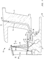
- FIG. 1 shows a schematic cross section of a side view of a portion of an exemplary embodiment of an ambient air cooling circuit 10, including: a source 12 of ambient air; at least one air supply passage 14 providing fluid communication between the source 12 and a pre-swirler plenum 16, and optionally being disposed in a strut 17 that supports a pre-swirler 18; a rotor cavity 20 adjacent to turbine blades 22; and a cooling channel inlet (not shown), a cooling channel 26, and a cooling channel outlet 29 in each of the turbine blades 22, which may or may not be disposed at a tip of the turbine blade 22.
- the ambient air becomes cooling fluid 28.
- the cooling fluid 28 travels through the air supply passage 14 where it enters the pre-swirler plenum 16, which is an annular shaped plenum that supplies the cooling fluid 28 to the pre-swirler 18.
- the pre-swirler 18 the cooling fluid 28 is swirled about a longitudinal axis 30 of the rotor disc 31.
- the cooling fluid 28 enters the cooling channel inlets, for example, either directly from the pre-swirler 18 or after the cooling fluid 28 travels through a gap between a rotor disc 31 and base of the turbine blade 22, and then the cooling fluid 28 travels through each cooling channel 26.
- a rotation of the turbine blades 22 about the longitudinal axis 30 of the rotor disc 31, (a.k.a.
- cooling fluid 28 creates a centrifugal force in a radially outward direction 32 that motivates the cooling fluid 28 through the cooling channels 26.
- the cooling fluid 28 is ejected from the cooling channel outlet 29 and into a hot gas path 34 in which hot gases 36 flow.
- the movement of the cooling fluid 28 through the cooling channels 26 and out the cooling channel outlet 29 creates a suction force that draws cooling fluid 28 from the rotor cavity 20 into the cooling channel 26 to replace the cooling fluid 28 that has been ejected.
- a static pressure of ambient air pushes cooling fluid 28 toward the rotor cavity 20 to replace cooling fluid 28 that is drawn into the cooling channels 26, thereby completing the ambient air cooling circuit 10.
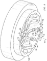
- FIG. 2 is a schematic perspective view of the pre-swirler 18 of the ambient air cooling circuit 10, from an aft end of the gas turbine engine, with an outer shroud removed. Visible are an inner shroud 38 having a constant diameter 40 and a plurality of guide vanes 42 disposed in an annular array about a longitudinal axis 30 of the rotor disc 31.
- the pre-swirler 18 receives an axially flowing, annular shaped flow of cooling fluid 28 delivered by the pre-swirler plenum 16 and imparts circumferential motion resulting in a swirl about the longitudinal axis 30 of the rotor disc 31. As can be seen in FIG.
- the plurality of guide vanes 42 define a plurality of nozzles 44 that guide the cooling fluid 28, each nozzle 44 being formed between and defined by a first guide vane 46; a circumferentially adjacent guide vane 48; an outer end wall 50 of an inner shroud 38, and an inner end wall 54 of an outer shroud 56 which the guide vanes 42 span.
- Each nozzle 44 therefore defines part of the cooling circuit 10.
- the end walls disclosed herein do not have a constant diameter 40. Instead, the end walls are contoured in both a circumferential direction 60 and an axial direction 62 and may undulate about the constant diameter 40.
- a horseshoe vortex 70 that may develop at an intersection 72 of a leading edge 74 of the guide vane 42 and an end wall. Within a nozzle 44 these vortices tend to develop in relatively slower regions of a flow of fluid where there is relatively higher static pressure. Cooling fluid near to the end walls and a pressure side 76 and/or a suction side 78 is slowed relative to other regions within the cooling fluid 28 by various aerodynamic factors, including friction associated with these surfaces. As a result, cooling fluid 28 in a region 80 proximate the intersections 72 may be relatively slow moving when compared to a central regions 82 within the nozzle 44.
- cooling fluid 28 encountering the leading edge 74 of the guide vane 42 causes a bow wave in front of the leading edge 74 where higher static pressure builds when compared to static pressure within other regions in the flow. Consequently, both relatively slow moving fluid and a relatively high static pressure exist in the region 80 proximate the intersections 72 when compared to the central regions 82 within the nozzle 44. Since the strength of a horseshoe vortex is related to a magnitude of a velocity gradient between the two regions and a magnitude of a static pressure gradient between the two regions, relatively strong horseshoe vortices 70 may develop in a nozzle 44 of the type disclosed herein. The losses associated with horseshoe vortices are magnified when guide vanes have a low aspect ratio.
- a shorter radial height and a longer length of the airfoil give the horseshoe vortex more opportunity to move closer to the central region 82. Consequently, the benefit of having contoured end walls (50, 54) in an exemplary embodiment of the pre-swirler 18 having low aspect ratio guide vanes 42 is also pronounced.
- cooling fluid 28 in a relatively faster moving region of a flow will tend to draw a leg 84 of the horseshoe vortex 70 toward the relatively faster moving region as the leg 84 flows downstream.
- the leg 84 of a radially inner horseshoe vortex 86 may be drawn in a radially outward direction 32. Drawing the leg 84 into the central region 82 within the nozzle 44 creates a greater amount of aerodynamic loss in the flow than would occur if the leg 84 were to remain in the region 80 proximate the intersections 72 where the flow rate is lower, and hence aerodynamic losses in the region are less problematic.
- the end walls disclosed herein are effective to reduce the velocity gradient and/or the static pressure gradient, which reduces the strength of the horseshoe vortex 70.
- the end wall geometry helps the leg 84 of the horseshoe vortex 70 remain closer to the region 80 proximate the intersections 72, thereby mitigating aerodynamic losses within the central region 82 within the nozzle 44.
- the contouring includes a hump 100, also seen as a raised area, on each end wall abutting the pressure side 76 of the guide vane 42.
- the hump 100 disclosed herein is a region where the end wall projects farther into a nozzle when compared to an end wall without a hump 100.
- the contouring further includes a valley 102, or recessed area, on each end wall between the guide vanes 42.
- the valley 102 disclosed herein is a region where the end wall recedes from a nozzle when compared to an end wall without a valley 102. Any region of a nozzle end wall without a hump 100 or a valley 102 may be considered a constant diameter region.
- Each end wall may have a respective constant diameter region, i.e.
- each end wall may have a hump 100 or valley 102 that occupies only a small portion of the respective end wall, or each end wall may be entirely defined by the hump 100 and valley 102, leaving no actual constant diameter (i.e. neutral) region.
- the hump 100 work together to cause the cooling fluid 28 in the region 80 proximate the intersections 72 to flow faster than if there were no hump 100 by decreasing a cross sectional area of the nozzle 44 in the region 80 proximate the intersections 72. With less area in which to flow, the cooling fluid 28 must necessarily speed up. It is also believed that the valleys 102 work together to cause the cooling fluid 28 in the central region 82 within the nozzle 44 to slow down due to the increased cross sectional area of the nozzle 44.
- a static pressure in the region 80 proximate the intersections 72 is relatively high due to the slow velocity of the cooling fluid 28.
- the static pressure decreases.
- valleys 102 a static pressure in the central region 82 within the nozzle 44 is relatively low due to the high velocity of the cooling fluid 28.
- the static pressure increases. Decreasing a relatively high static pressure in the region 80 proximate the intersections 72, and increasing the relatively low static pressure in the central region 82 within the nozzle 44 yields a smaller pressure gradient which, in turn, yields a weaker horseshoe vortex 70.
- FIG. 4 is a cutaway view of the pre-swirler 18 of FIG. 3 , showing a radially inward portion of the guide vanes 42 and the inner shroud 38, with a radially outward portion of the guide vanes 42 and the outer shroud 56 removed.
- a radially inward portion of a plurality of nozzles 44 is shown, each being defined in part by the outer end wall 50 of the inner shroud 38, a pressure side 76 of a first guide vane 46 and a suction side 78 of the circumferentially adjacent guide vane 48.
- Cooling fluid 28 enters an inlet end 110 of the nozzle 44 while traveling primarily in an axial direction with respect to the longitudinal axis 30 of the rotor disc 31, and exits from an outlet end 112 traveling in a direction of travel having a component in the axial direction and a component in the circumferential direction 60.
- the inner shroud 38 and/or the outer shroud 56 can be a monolithic body.
- Vane assemblies used to guide combustion gases in turbines are conventionally made of subcomponents that are assembled into a ring of vanes. Such a configuration is necessary due to factors associated with the larger size of these vane rings, including a high cost to manufacture a single body of this size, thermal growth problems, and assembly and disassembly of the turbine itself which often necessitates disassembling the vane ring.
- These assembled vane rings often have joints between the subcomponents that change throughout operation. For example, there may be no circumferential gap in the nozzle between adjacent subcomponents, or there may be a circumferential gap. This alone provides for varying aerodynamics.
- the joint may or may not be radially aligned.
- one subcomponent may extend radially further out than another.
- the gases may encounter a step. It may be a step up or a step down, depending on whether the first subcomponent extends radially farther outward than the adjacent subcomponent, or does not extend radially as far. Both types of steps create vortices in the flow, and these vortices create the same type of aerodynamic losses that the horseshoe vortices 70 do.
- the inner shroud 38 and the outer shroud 56 do not suffer from the foregoing limitations and therefore they can be manufactured as a single piece component. Having a single piece/monolithic construction allows the nozzles to avoid the aerodynamic losses associated with joints between assembled subcomponents. This, in turn, leads to lower pressure loss resulting from travel through the nozzle 44.
- FIG. 5 is a cutaway view of the pre-swirler 18 of FIG. 3 , showing a radially outward portion of the guide vanes 42 and the outer shroud 56, with a radially inward portion of the guide vanes 42 and the inner shroud 38 removed.
- a radially outward portion of a plurality of nozzles 44 is shown, each being defined in part by the inner end wall 54 of an outer shroud 56, a pressure side 76 of a first guide vane 46 and a suction side 78 of the circumferentially adjacent guide vane 48.
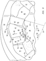
- FIG. 6 is a top view showing a topography of an exemplary embodiment of the inner shroud 38 of the pre-swirler 18.
- the hump 100 is visible adjacent to the pressure side 76 of the first guide vane 46 and a peak of the hump 100 may be disposed approximate one third of the way down a chord line 122 from the leading edge 74 of the first guide vane to a trailing edge 126.
- the valley 102 is visible in a circumferential direction 60 approximately half way between the first guide vane 46 and the circumferentially adjacent guide vane 48.
- Horseshoe vortex 70 is visible emanating from the leading edge 74 of the first guide vane 46.
- a lowest point 120 of the valley is disposed approximately two thirds of the way down the chord line 122 from the leading edge 74 of the first guide vane to the trailing edge 126. It is also located downstream of the leg 84 of the horseshoe vortex 70 such that the leg 84 is forced to travel over (as seen in FIG. 6 ) the valley 102.
- FIG. 7 is a view showing a topography of an exemplary embodiment of the outer shroud 56 of the pre-swirler 18, as though looking radially inward at a mirror placed on the hub under the outer shroud 56. Since the outer shroud 56 is radially farther outward it is longer, and therefore there is more space between adjacent guide vanes 42. By eliminating this extra length to match the size of FIG. 6 the hump 100 and valleys 102 appear smaller, but may actually be not smaller.
- the humps 100 and valleys 102 shown are exemplary. Any contour that produces the desired aerodynamic affects is considered to be within the scope of the disclosure.
- FIG. 8 is an illustration of a streamline of the cooling fluid 28 in a pre-swirler without features disclosed herein using fluid modeling.
- Streamline 124 represents leg 84 of horseshoe vortex 70. It can be seen that upon encountering the leading edge 74 of the first guide vane 46 leg 84 begins to separate from the pressure side of the first guide vane 46. As it traverses the nozzle 44 the streamline 124 migrates toward the suction side 78 of the circumferentially adjacent guide vane 48 toward the trailing edge 126 of the circumferentially adjacent guide vane 48. While doing this the streamline 124 is also moving upward, out of a plane of the paper, toward the central region 82 within the nozzle 44, and causing aerodynamic losses.
- FIG. 9 is an illustration of a streamline of the cooling fluid 28 in a pre-swirler 18 having the features disclosed herein using fluid modeling.
- the streamline 124 of the leg 84 of the horseshoe vortex 70 departs slightly from the pressure side 76.
- the streamline 124 does not migrate toward the suction side 78 of the circumferentially adjacent guide vane 48 as it travels within the nozzle 44 toward the trailing edge 126 of the circumferentially adjacent guide vane 48. Instead, the streamline 124 adheres to the pressure side 76 of the first guide vane 46 for a longer distance.
- the streamline 124 is less likely to depart from the plane of the paper to the same degree.
- the leg 84 of the horseshoe vortex 70 generates less aerodynamic loss, yielding more efficient operation of the gas turbine engine.
Landscapes
- Engineering & Computer Science (AREA)
- Physics & Mathematics (AREA)
- Fluid Mechanics (AREA)
- Mechanical Engineering (AREA)
- General Engineering & Computer Science (AREA)
- Turbine Rotor Nozzle Sealing (AREA)
Claims (8)
- Gasturbinenmotor, der Folgendes umfasst:einen Umgebungsluft-Kühlkreislauf (10), der einen Kühlkanal (26) umfasst, der in einer Turbinenschaufel (22) angeordnet ist und in fluidischer Kommunikation mit einer Quelle (12) von Umgebungsluft steht, die Kühlflüssigkeit (28) bereitstellt, undeine Vorverwirbelungsanordnung (18), die Folgendes umfasst:ein Innendeckband (38),ein Außendeckband (56) undeine Mehrzahl von Leitschaufeln (42), die sich jeweils von dem Innendeckband (38) zu dem Außendeckband (56) erstrecken,wobei in Umfangsrichtung benachbarte Leitschaufeln (42) jeweilige Düsen (44) dazwischen definieren, wobei die Düsen (44) einen Abschnitt des Kühlkreislaufs (10) definieren, wobei jede Düse (44) durch eine Druckseite (76) einer ersten Leitschaufel (42), eine Saugseite (78) der benachbarten Leitschaufel (42) definiert wird, eine äußere Endwand (50) durch das Innendeckband (38) definiert wird und eine innere Endwand (54) durch das Außendeckband (56) definiert wird,wobei die durch eine Drehung der Turbinenschaufel (22) erzeugten Kräfte die Kühlflüssigkeit (28) durch den Kühlkreislauf (10) befördern,wobei die Vorverwirbelungsanordnung (18) dazu konfiguriert ist, die durch die Düsen (44) gezogene Kühlflüssigkeit (28) in einen Wirbel zu versetzen und die verwirbelte Kühlflüssigkeit (28) zu einer Basis der Turbinenschaufel (22) zu leiten.
- Gasturbinenmotor nach Anspruch 1, wobei das Innendeckband (38) als monolithischer Körper ausgebildet ist.
- Gasturbinenmotor nach Anspruch 1, wobei das Außendeckband (56) als monolithischer Körper ausgebildet ist.
- Gasturbinenmotor nach Anspruch 1, wobei die innere Endwand (54) und die äußere Endwand (50) jeweils eine Mulde (102) umfassen, die zwischen den benachbarten Leitschaufeln (42) angeordnet ist.
- Gasturbinenmotor nach Anspruch 1, wobei die innere Endwand (54) und die äußere Endwand (50) jeweils einen Höcker (100) umfassen, der an die Druckseite (76) der ersten Leitschaufel (42) angrenzt.
- Gasturbinenmotor nach Anspruch 5, wobei eine Spitze des Höckers (100) bei etwa einem Drittel einer Länge einer Profilsehne(122) der ersten Leitschaufel (42) von einer Vorderkante (74) der ersten Leitschaufel (42) angeordnet ist.
- Gasturbinenmotor nach Anspruch 1, wobei der Kühlkreislauf (10) ferner einen Luftzuführdurchgang (14) umfasst, der dazu konfiguriert ist, die Kühlflüssigkeit (28) von der Quelle (12) der Umgebungsluft an die Vorverwirbelungsanordnung (18) zu liefern.
- Gasturbinenmotor nach Anspruch 7, der ferner eine Strebe (17) umfasst, die die Vorverwirbelungsanordnung (18), in dem der Luftzuführdurchgang (14) angeordnet ist, unterstützt.
Applications Claiming Priority (2)
| Application Number | Priority Date | Filing Date | Title |
|---|---|---|---|
| US13/766,909 US8926267B2 (en) | 2011-04-12 | 2013-02-14 | Ambient air cooling arrangement having a pre-swirler for gas turbine engine blade cooling |
| PCT/US2014/016014 WO2014126994A1 (en) | 2013-02-14 | 2014-02-12 | Gas turbine engine with an ambient air cooling arrangement having a pre-swirler |
Publications (2)
| Publication Number | Publication Date |
|---|---|
| EP2956624A1 EP2956624A1 (de) | 2015-12-23 |
| EP2956624B1 true EP2956624B1 (de) | 2020-12-30 |
Family
ID=50156985
Family Applications (1)
| Application Number | Title | Priority Date | Filing Date |
|---|---|---|---|
| EP14706248.3A Active EP2956624B1 (de) | 2013-02-14 | 2014-02-12 | Gasturbinenmotor mit einer umgebungsluftkühlanordnung mit verwirbelungsanordnung |
Country Status (6)
| Country | Link |
|---|---|
| EP (1) | EP2956624B1 (de) |
| JP (1) | JP6173489B2 (de) |
| CN (1) | CN105392964B (de) |
| RU (1) | RU2618153C2 (de) |
| SA (1) | SA515360813B1 (de) |
| WO (1) | WO2014126994A1 (de) |
Cited By (1)
| Publication number | Priority date | Publication date | Assignee | Title |
|---|---|---|---|---|
| EP4524366A3 (de) * | 2023-09-15 | 2025-09-03 | RTX Corporation | Mehrteilige einspritzdüse für einen turbinenmotor |
Families Citing this family (7)
| Publication number | Priority date | Publication date | Assignee | Title |
|---|---|---|---|---|
| CN106014486A (zh) * | 2016-08-09 | 2016-10-12 | 上海电气燃气轮机有限公司 | 一种燃气轮机透平冷却气路和燃气轮机 |
| US11396888B1 (en) | 2017-11-09 | 2022-07-26 | Williams International Co., L.L.C. | System and method for guiding compressible gas flowing through a duct |
| CN110145374B (zh) * | 2018-02-14 | 2021-07-30 | 中国航发商用航空发动机有限责任公司 | 发动机预旋系统 |
| ES2997484T3 (en) * | 2018-07-18 | 2025-02-17 | Tenova Spa | Improved process and plant for preheating a metal charge fed in continuous to an electric melting furnace |
| JP7216249B2 (ja) | 2019-07-25 | 2023-01-31 | シーメンス エナジー グローバル ゲゼルシャフト ミット ベシュレンクテル ハフツング ウント コンパニー コマンディートゲゼルシャフト | ガスタービン・エンジンの予旋回装置の調整 |
| CA3227134A1 (en) | 2021-09-22 | 2023-03-30 | Exonetik Turbo Inc. | Rim-rotor turbine sealing and cooling arrangement |
| CN116220913B (zh) * | 2023-05-08 | 2023-08-18 | 中国航发四川燃气涡轮研究院 | 一种低损失的发动机预旋供气系统 |
Family Cites Families (14)
| Publication number | Priority date | Publication date | Assignee | Title |
|---|---|---|---|---|
| JP3653114B2 (ja) * | 1995-02-03 | 2005-05-25 | ユナイテッド テクノロジーズ コーポレイション | ステータベーン構造 |
| RU2289029C2 (ru) * | 2004-02-05 | 2006-12-10 | Государственное предприятие "Запорожское машиностроительное конструкторское бюро "Прогресс" им. акад. А.Г. Ивченко" | Устройство подвода охлаждающего воздуха к рабочим лопаткам колеса турбины |
| US7134842B2 (en) * | 2004-12-24 | 2006-11-14 | General Electric Company | Scalloped surface turbine stage |
| GB0518628D0 (en) * | 2005-09-13 | 2005-10-19 | Rolls Royce Plc | Axial compressor blading |
| US7870742B2 (en) * | 2006-11-10 | 2011-01-18 | General Electric Company | Interstage cooled turbine engine |
| JP2008144687A (ja) * | 2006-12-12 | 2008-06-26 | Mitsubishi Heavy Ind Ltd | タービン静翼構造 |
| US8118556B2 (en) * | 2007-01-31 | 2012-02-21 | Caterpillar Inc. | Compressor wheel for a turbocharger system |
| US8079802B2 (en) * | 2008-06-30 | 2011-12-20 | Mitsubishi Heavy Industries, Ltd. | Gas turbine |
| US8647067B2 (en) * | 2008-12-09 | 2014-02-11 | General Electric Company | Banked platform turbine blade |
| RU2443869C2 (ru) * | 2010-02-19 | 2012-02-27 | Вячеслав Евгеньевич Беляев | Устройство для охлаждения ротора газовой турбины |
| US8613199B2 (en) * | 2010-04-12 | 2013-12-24 | Siemens Energy, Inc. | Cooling fluid metering structure in a gas turbine engine |
| US8684684B2 (en) * | 2010-08-31 | 2014-04-01 | General Electric Company | Turbine assembly with end-wall-contoured airfoils and preferenttial clocking |
| ES2440563T3 (es) * | 2011-02-08 | 2014-01-29 | MTU Aero Engines AG | Canal de álabe con contornos de pared lateral y correspondiente aparato de flujo |
| US8684666B2 (en) * | 2011-04-12 | 2014-04-01 | Siemens Energy, Inc. | Low pressure cooling seal system for a gas turbine engine |
-
2014
- 2014-02-12 JP JP2015558100A patent/JP6173489B2/ja active Active
- 2014-02-12 EP EP14706248.3A patent/EP2956624B1/de active Active
- 2014-02-12 WO PCT/US2014/016014 patent/WO2014126994A1/en not_active Ceased
- 2014-02-12 CN CN201480008673.XA patent/CN105392964B/zh active Active
- 2014-02-12 RU RU2015134151A patent/RU2618153C2/ru active
-
2015
- 2015-07-27 SA SA515360813A patent/SA515360813B1/ar unknown
Non-Patent Citations (1)
| Title |
|---|
| None * |
Cited By (1)
| Publication number | Priority date | Publication date | Assignee | Title |
|---|---|---|---|---|
| EP4524366A3 (de) * | 2023-09-15 | 2025-09-03 | RTX Corporation | Mehrteilige einspritzdüse für einen turbinenmotor |
Also Published As
| Publication number | Publication date |
|---|---|
| JP6173489B2 (ja) | 2017-08-02 |
| WO2014126994A1 (en) | 2014-08-21 |
| RU2015134151A (ru) | 2017-03-20 |
| CN105392964B (zh) | 2018-04-13 |
| RU2618153C2 (ru) | 2017-05-02 |
| EP2956624A1 (de) | 2015-12-23 |
| JP2016508570A (ja) | 2016-03-22 |
| SA515360813B1 (ar) | 2018-08-29 |
| CN105392964A (zh) | 2016-03-09 |
Similar Documents
| Publication | Publication Date | Title |
|---|---|---|
| US8926267B2 (en) | Ambient air cooling arrangement having a pre-swirler for gas turbine engine blade cooling | |
| EP2956624B1 (de) | Gasturbinenmotor mit einer umgebungsluftkühlanordnung mit verwirbelungsanordnung | |
| US10577955B2 (en) | Airfoil assembly with a scalloped flow surface | |
| US9863254B2 (en) | Turbine airfoil with local wall thickness control | |
| EP2666964B1 (de) | Gasturbinenschaufel mit Kühlungslochgräben | |
| US9726024B2 (en) | Airfoil cooling circuit | |
| US10577943B2 (en) | Turbine engine airfoil insert | |
| US10815806B2 (en) | Engine component with insert | |
| JP2014513230A (ja) | 高キャンバ圧縮機ロータブレード | |
| US20150159488A1 (en) | Turbine rotor blade of a gas turbine and method for cooling a blade tip of a turbine rotor blade of a gas turbine | |
| US10590781B2 (en) | Turbine engine assembly with a component having a leading edge trough | |
| US10830057B2 (en) | Airfoil with tip rail cooling | |
| EP2960434A1 (de) | Verdichterprofil und zugehörige Verdichterrotorbaugruppe | |
| CN109083688B (zh) | 具有偏转器的涡轮发动机部件 | |
| US10450874B2 (en) | Airfoil for a gas turbine engine | |
| US10837291B2 (en) | Turbine engine with component having a cooled tip | |
| US10697301B2 (en) | Turbine engine airfoil having a cooling circuit | |
| US11939880B1 (en) | Airfoil assembly with flow surface | |
| US9631509B1 (en) | Rim seal arrangement having pumping feature | |
| US20180128113A1 (en) | Airfoil assembly with a cooling circuit | |
| JP2019031973A (ja) | 不均一なシェブロンピンを備えたエンジン構成要素 | |
| US10612421B2 (en) | Gas turbine exhaust assembly | |
| CN107762564A (zh) | 带有多孔肋部的用于涡轮发动机的翼型件 | |
| US11242770B2 (en) | Turbine center frame and method | |
| CN109083687B (zh) | 最小化横穿冷却孔的横流的方法和用于涡轮发动机的部件 |
Legal Events
| Date | Code | Title | Description |
|---|---|---|---|
| PUAI | Public reference made under article 153(3) epc to a published international application that has entered the european phase |
Free format text: ORIGINAL CODE: 0009012 |
|
| 17P | Request for examination filed |
Effective date: 20150713 |
|
| AK | Designated contracting states |
Kind code of ref document: A1 Designated state(s): AL AT BE BG CH CY CZ DE DK EE ES FI FR GB GR HR HU IE IS IT LI LT LU LV MC MK MT NL NO PL PT RO RS SE SI SK SM TR |
|
| AX | Request for extension of the european patent |
Extension state: BA ME |
|
| DAX | Request for extension of the european patent (deleted) | ||
| GRAP | Despatch of communication of intention to grant a patent |
Free format text: ORIGINAL CODE: EPIDOSNIGR1 |
|
| STAA | Information on the status of an ep patent application or granted ep patent |
Free format text: STATUS: GRANT OF PATENT IS INTENDED |
|
| INTG | Intention to grant announced |
Effective date: 20200908 |
|
| GRAS | Grant fee paid |
Free format text: ORIGINAL CODE: EPIDOSNIGR3 |
|
| GRAA | (expected) grant |
Free format text: ORIGINAL CODE: 0009210 |
|
| STAA | Information on the status of an ep patent application or granted ep patent |
Free format text: STATUS: THE PATENT HAS BEEN GRANTED |
|
| RIN1 | Information on inventor provided before grant (corrected) |
Inventor name: LEE, CHING-PANG Inventor name: MARRA, JOHN J. Inventor name: MILLER, JR., SAMUEL R. Inventor name: SCHROEDER, ERIC Inventor name: THAM, KOK-MUN Inventor name: MEEROFF, JAMIE |
|
| AK | Designated contracting states |
Kind code of ref document: B1 Designated state(s): AL AT BE BG CH CY CZ DE DK EE ES FI FR GB GR HR HU IE IS IT LI LT LU LV MC MK MT NL NO PL PT RO RS SE SI SK SM TR |
|
| REG | Reference to a national code |
Ref country code: GB Ref legal event code: FG4D |
|
| REG | Reference to a national code |
Ref country code: AT Ref legal event code: REF Ref document number: 1350104 Country of ref document: AT Kind code of ref document: T Effective date: 20210115 |
|
| REG | Reference to a national code |
Ref country code: DE Ref legal event code: R096 Ref document number: 602014073769 Country of ref document: DE |
|
| REG | Reference to a national code |
Ref country code: IE Ref legal event code: FG4D |
|
| REG | Reference to a national code |
Ref country code: CH Ref legal event code: NV Representative=s name: SIEMENS SCHWEIZ AG, CH |
|
| PG25 | Lapsed in a contracting state [announced via postgrant information from national office to epo] |
Ref country code: GR Free format text: LAPSE BECAUSE OF FAILURE TO SUBMIT A TRANSLATION OF THE DESCRIPTION OR TO PAY THE FEE WITHIN THE PRESCRIBED TIME-LIMIT Effective date: 20210331 Ref country code: FI Free format text: LAPSE BECAUSE OF FAILURE TO SUBMIT A TRANSLATION OF THE DESCRIPTION OR TO PAY THE FEE WITHIN THE PRESCRIBED TIME-LIMIT Effective date: 20201230 Ref country code: RS Free format text: LAPSE BECAUSE OF FAILURE TO SUBMIT A TRANSLATION OF THE DESCRIPTION OR TO PAY THE FEE WITHIN THE PRESCRIBED TIME-LIMIT Effective date: 20201230 Ref country code: NO Free format text: LAPSE BECAUSE OF FAILURE TO SUBMIT A TRANSLATION OF THE DESCRIPTION OR TO PAY THE FEE WITHIN THE PRESCRIBED TIME-LIMIT Effective date: 20210330 |
|
| REG | Reference to a national code |
Ref country code: AT Ref legal event code: MK05 Ref document number: 1350104 Country of ref document: AT Kind code of ref document: T Effective date: 20201230 |
|
| PG25 | Lapsed in a contracting state [announced via postgrant information from national office to epo] |
Ref country code: LV Free format text: LAPSE BECAUSE OF FAILURE TO SUBMIT A TRANSLATION OF THE DESCRIPTION OR TO PAY THE FEE WITHIN THE PRESCRIBED TIME-LIMIT Effective date: 20201230 Ref country code: SE Free format text: LAPSE BECAUSE OF FAILURE TO SUBMIT A TRANSLATION OF THE DESCRIPTION OR TO PAY THE FEE WITHIN THE PRESCRIBED TIME-LIMIT Effective date: 20201230 Ref country code: BG Free format text: LAPSE BECAUSE OF FAILURE TO SUBMIT A TRANSLATION OF THE DESCRIPTION OR TO PAY THE FEE WITHIN THE PRESCRIBED TIME-LIMIT Effective date: 20210330 |
|
| REG | Reference to a national code |
Ref country code: NL Ref legal event code: MP Effective date: 20201230 |
|
| PG25 | Lapsed in a contracting state [announced via postgrant information from national office to epo] |
Ref country code: HR Free format text: LAPSE BECAUSE OF FAILURE TO SUBMIT A TRANSLATION OF THE DESCRIPTION OR TO PAY THE FEE WITHIN THE PRESCRIBED TIME-LIMIT Effective date: 20201230 |
|
| REG | Reference to a national code |
Ref country code: LT Ref legal event code: MG9D |
|
| PG25 | Lapsed in a contracting state [announced via postgrant information from national office to epo] |
Ref country code: RO Free format text: LAPSE BECAUSE OF FAILURE TO SUBMIT A TRANSLATION OF THE DESCRIPTION OR TO PAY THE FEE WITHIN THE PRESCRIBED TIME-LIMIT Effective date: 20201230 Ref country code: SK Free format text: LAPSE BECAUSE OF FAILURE TO SUBMIT A TRANSLATION OF THE DESCRIPTION OR TO PAY THE FEE WITHIN THE PRESCRIBED TIME-LIMIT Effective date: 20201230 Ref country code: PT Free format text: LAPSE BECAUSE OF FAILURE TO SUBMIT A TRANSLATION OF THE DESCRIPTION OR TO PAY THE FEE WITHIN THE PRESCRIBED TIME-LIMIT Effective date: 20210430 Ref country code: LT Free format text: LAPSE BECAUSE OF FAILURE TO SUBMIT A TRANSLATION OF THE DESCRIPTION OR TO PAY THE FEE WITHIN THE PRESCRIBED TIME-LIMIT Effective date: 20201230 Ref country code: CZ Free format text: LAPSE BECAUSE OF FAILURE TO SUBMIT A TRANSLATION OF THE DESCRIPTION OR TO PAY THE FEE WITHIN THE PRESCRIBED TIME-LIMIT Effective date: 20201230 Ref country code: EE Free format text: LAPSE BECAUSE OF FAILURE TO SUBMIT A TRANSLATION OF THE DESCRIPTION OR TO PAY THE FEE WITHIN THE PRESCRIBED TIME-LIMIT Effective date: 20201230 Ref country code: NL Free format text: LAPSE BECAUSE OF FAILURE TO SUBMIT A TRANSLATION OF THE DESCRIPTION OR TO PAY THE FEE WITHIN THE PRESCRIBED TIME-LIMIT Effective date: 20201230 |
|
| PG25 | Lapsed in a contracting state [announced via postgrant information from national office to epo] |
Ref country code: PL Free format text: LAPSE BECAUSE OF FAILURE TO SUBMIT A TRANSLATION OF THE DESCRIPTION OR TO PAY THE FEE WITHIN THE PRESCRIBED TIME-LIMIT Effective date: 20201230 Ref country code: AT Free format text: LAPSE BECAUSE OF FAILURE TO SUBMIT A TRANSLATION OF THE DESCRIPTION OR TO PAY THE FEE WITHIN THE PRESCRIBED TIME-LIMIT Effective date: 20201230 |
|
| PG25 | Lapsed in a contracting state [announced via postgrant information from national office to epo] |
Ref country code: IS Free format text: LAPSE BECAUSE OF FAILURE TO SUBMIT A TRANSLATION OF THE DESCRIPTION OR TO PAY THE FEE WITHIN THE PRESCRIBED TIME-LIMIT Effective date: 20210430 Ref country code: MC Free format text: LAPSE BECAUSE OF FAILURE TO SUBMIT A TRANSLATION OF THE DESCRIPTION OR TO PAY THE FEE WITHIN THE PRESCRIBED TIME-LIMIT Effective date: 20201230 |
|
| REG | Reference to a national code |
Ref country code: DE Ref legal event code: R097 Ref document number: 602014073769 Country of ref document: DE |
|
| REG | Reference to a national code |
Ref country code: BE Ref legal event code: MM Effective date: 20210228 |
|
| PG25 | Lapsed in a contracting state [announced via postgrant information from national office to epo] |
Ref country code: LU Free format text: LAPSE BECAUSE OF NON-PAYMENT OF DUE FEES Effective date: 20210212 Ref country code: AL Free format text: LAPSE BECAUSE OF FAILURE TO SUBMIT A TRANSLATION OF THE DESCRIPTION OR TO PAY THE FEE WITHIN THE PRESCRIBED TIME-LIMIT Effective date: 20201230 |
|
| PLBE | No opposition filed within time limit |
Free format text: ORIGINAL CODE: 0009261 |
|
| STAA | Information on the status of an ep patent application or granted ep patent |
Free format text: STATUS: NO OPPOSITION FILED WITHIN TIME LIMIT |
|
| PG25 | Lapsed in a contracting state [announced via postgrant information from national office to epo] |
Ref country code: ES Free format text: LAPSE BECAUSE OF FAILURE TO SUBMIT A TRANSLATION OF THE DESCRIPTION OR TO PAY THE FEE WITHIN THE PRESCRIBED TIME-LIMIT Effective date: 20201230 Ref country code: DK Free format text: LAPSE BECAUSE OF FAILURE TO SUBMIT A TRANSLATION OF THE DESCRIPTION OR TO PAY THE FEE WITHIN THE PRESCRIBED TIME-LIMIT Effective date: 20201230 |
|
| 26N | No opposition filed |
Effective date: 20211001 |
|
| PG25 | Lapsed in a contracting state [announced via postgrant information from national office to epo] |
Ref country code: IE Free format text: LAPSE BECAUSE OF NON-PAYMENT OF DUE FEES Effective date: 20210212 |
|
| PG25 | Lapsed in a contracting state [announced via postgrant information from national office to epo] |
Ref country code: SI Free format text: LAPSE BECAUSE OF FAILURE TO SUBMIT A TRANSLATION OF THE DESCRIPTION OR TO PAY THE FEE WITHIN THE PRESCRIBED TIME-LIMIT Effective date: 20201230 |
|
| PG25 | Lapsed in a contracting state [announced via postgrant information from national office to epo] |
Ref country code: IS Free format text: LAPSE BECAUSE OF FAILURE TO SUBMIT A TRANSLATION OF THE DESCRIPTION OR TO PAY THE FEE WITHIN THE PRESCRIBED TIME-LIMIT Effective date: 20210430 |
|
| PG25 | Lapsed in a contracting state [announced via postgrant information from national office to epo] |
Ref country code: BE Free format text: LAPSE BECAUSE OF NON-PAYMENT OF DUE FEES Effective date: 20210228 |
|
| REG | Reference to a national code |
Ref country code: DE Ref legal event code: R082 Ref document number: 602014073769 Country of ref document: DE Representative=s name: ROTH, THOMAS, DIPL.-PHYS. DR., DE |
|
| PG25 | Lapsed in a contracting state [announced via postgrant information from national office to epo] |
Ref country code: HU Free format text: LAPSE BECAUSE OF FAILURE TO SUBMIT A TRANSLATION OF THE DESCRIPTION OR TO PAY THE FEE WITHIN THE PRESCRIBED TIME-LIMIT; INVALID AB INITIO Effective date: 20140212 |
|
| PG25 | Lapsed in a contracting state [announced via postgrant information from national office to epo] |
Ref country code: CY Free format text: LAPSE BECAUSE OF FAILURE TO SUBMIT A TRANSLATION OF THE DESCRIPTION OR TO PAY THE FEE WITHIN THE PRESCRIBED TIME-LIMIT Effective date: 20201230 |
|
| PG25 | Lapsed in a contracting state [announced via postgrant information from national office to epo] |
Ref country code: SM Free format text: LAPSE BECAUSE OF FAILURE TO SUBMIT A TRANSLATION OF THE DESCRIPTION OR TO PAY THE FEE WITHIN THE PRESCRIBED TIME-LIMIT Effective date: 20201230 |
|
| PG25 | Lapsed in a contracting state [announced via postgrant information from national office to epo] |
Ref country code: MK Free format text: LAPSE BECAUSE OF FAILURE TO SUBMIT A TRANSLATION OF THE DESCRIPTION OR TO PAY THE FEE WITHIN THE PRESCRIBED TIME-LIMIT Effective date: 20201230 |
|
| PG25 | Lapsed in a contracting state [announced via postgrant information from national office to epo] |
Ref country code: MT Free format text: LAPSE BECAUSE OF FAILURE TO SUBMIT A TRANSLATION OF THE DESCRIPTION OR TO PAY THE FEE WITHIN THE PRESCRIBED TIME-LIMIT Effective date: 20201230 |
|
| PG25 | Lapsed in a contracting state [announced via postgrant information from national office to epo] |
Ref country code: TR Free format text: LAPSE BECAUSE OF FAILURE TO SUBMIT A TRANSLATION OF THE DESCRIPTION OR TO PAY THE FEE WITHIN THE PRESCRIBED TIME-LIMIT Effective date: 20201230 |
|
| REG | Reference to a national code |
Ref country code: CH Ref legal event code: U11 Free format text: ST27 STATUS EVENT CODE: U-0-0-U10-U11 (AS PROVIDED BY THE NATIONAL OFFICE) Effective date: 20260301 |
|
| PGFP | Annual fee paid to national office [announced via postgrant information from national office to epo] |
Ref country code: GB Payment date: 20260223 Year of fee payment: 13 |
|
| PGFP | Annual fee paid to national office [announced via postgrant information from national office to epo] |
Ref country code: DE Payment date: 20260220 Year of fee payment: 13 |
|
| PGFP | Annual fee paid to national office [announced via postgrant information from national office to epo] |
Ref country code: IT Payment date: 20260220 Year of fee payment: 13 |
|
| PGFP | Annual fee paid to national office [announced via postgrant information from national office to epo] |
Ref country code: FR Payment date: 20260224 Year of fee payment: 13 |
|
| PGFP | Annual fee paid to national office [announced via postgrant information from national office to epo] |
Ref country code: CH Payment date: 20260301 Year of fee payment: 13 |