EP2956679B1 - Actionneur modulaire à agencement de retenue - Google Patents
Actionneur modulaire à agencement de retenue Download PDFInfo
- Publication number
- EP2956679B1 EP2956679B1 EP14751849.2A EP14751849A EP2956679B1 EP 2956679 B1 EP2956679 B1 EP 2956679B1 EP 14751849 A EP14751849 A EP 14751849A EP 2956679 B1 EP2956679 B1 EP 2956679B1
- Authority
- EP
- European Patent Office
- Prior art keywords
- piston
- retention wire
- linear actuator
- chamber
- piston rod
- Prior art date
- Legal status (The legal status is an assumption and is not a legal conclusion. Google has not performed a legal analysis and makes no representation as to the accuracy of the status listed.)
- Active
Links
Images






Classifications
-
- F—MECHANICAL ENGINEERING; LIGHTING; HEATING; WEAPONS; BLASTING
- F15—FLUID-PRESSURE ACTUATORS; HYDRAULICS OR PNEUMATICS IN GENERAL
- F15B—SYSTEMS ACTING BY MEANS OF FLUIDS IN GENERAL; FLUID-PRESSURE ACTUATORS, e.g. SERVOMOTORS; DETAILS OF FLUID-PRESSURE SYSTEMS, NOT OTHERWISE PROVIDED FOR
- F15B15/00—Fluid-actuated devices for displacing a member from one position to another; Gearing associated therewith
- F15B15/20—Other details, e.g. assembly with regulating devices
- F15B15/22—Other details, e.g. assembly with regulating devices for accelerating or decelerating the stroke
- F15B15/222—Other details, e.g. assembly with regulating devices for accelerating or decelerating the stroke having a piston with a piston extension or piston recess which throttles the main fluid outlet as the piston approaches its end position
-
- F—MECHANICAL ENGINEERING; LIGHTING; HEATING; WEAPONS; BLASTING
- F15—FLUID-PRESSURE ACTUATORS; HYDRAULICS OR PNEUMATICS IN GENERAL
- F15B—SYSTEMS ACTING BY MEANS OF FLUIDS IN GENERAL; FLUID-PRESSURE ACTUATORS, e.g. SERVOMOTORS; DETAILS OF FLUID-PRESSURE SYSTEMS, NOT OTHERWISE PROVIDED FOR
- F15B15/00—Fluid-actuated devices for displacing a member from one position to another; Gearing associated therewith
- F15B15/08—Characterised by the construction of the motor unit
- F15B15/14—Characterised by the construction of the motor unit of the straight-cylinder type
- F15B15/1423—Component parts; Constructional details
- F15B15/1438—Cylinder to end cap assemblies
-
- F—MECHANICAL ENGINEERING; LIGHTING; HEATING; WEAPONS; BLASTING
- F15—FLUID-PRESSURE ACTUATORS; HYDRAULICS OR PNEUMATICS IN GENERAL
- F15B—SYSTEMS ACTING BY MEANS OF FLUIDS IN GENERAL; FLUID-PRESSURE ACTUATORS, e.g. SERVOMOTORS; DETAILS OF FLUID-PRESSURE SYSTEMS, NOT OTHERWISE PROVIDED FOR
- F15B15/00—Fluid-actuated devices for displacing a member from one position to another; Gearing associated therewith
- F15B15/08—Characterised by the construction of the motor unit
- F15B15/14—Characterised by the construction of the motor unit of the straight-cylinder type
- F15B15/1423—Component parts; Constructional details
- F15B15/1447—Pistons; Piston to piston rod assemblies
-
- F—MECHANICAL ENGINEERING; LIGHTING; HEATING; WEAPONS; BLASTING
- F15—FLUID-PRESSURE ACTUATORS; HYDRAULICS OR PNEUMATICS IN GENERAL
- F15B—SYSTEMS ACTING BY MEANS OF FLUIDS IN GENERAL; FLUID-PRESSURE ACTUATORS, e.g. SERVOMOTORS; DETAILS OF FLUID-PRESSURE SYSTEMS, NOT OTHERWISE PROVIDED FOR
- F15B15/00—Fluid-actuated devices for displacing a member from one position to another; Gearing associated therewith
- F15B15/08—Characterised by the construction of the motor unit
- F15B15/14—Characterised by the construction of the motor unit of the straight-cylinder type
- F15B15/1423—Component parts; Constructional details
- F15B15/1457—Piston rods
-
- F—MECHANICAL ENGINEERING; LIGHTING; HEATING; WEAPONS; BLASTING
- F16—ENGINEERING ELEMENTS AND UNITS; GENERAL MEASURES FOR PRODUCING AND MAINTAINING EFFECTIVE FUNCTIONING OF MACHINES OR INSTALLATIONS; THERMAL INSULATION IN GENERAL
- F16F—SPRINGS; SHOCK-ABSORBERS; MEANS FOR DAMPING VIBRATION
- F16F9/00—Springs, vibration-dampers, shock-absorbers, or similarly-constructed movement-dampers using a fluid or the equivalent as damping medium
- F16F9/32—Details
- F16F9/3207—Constructional features
- F16F9/3235—Constructional features of cylinders
- F16F9/3242—Constructional features of cylinders of cylinder ends, e.g. caps
-
- F—MECHANICAL ENGINEERING; LIGHTING; HEATING; WEAPONS; BLASTING
- F16—ENGINEERING ELEMENTS AND UNITS; GENERAL MEASURES FOR PRODUCING AND MAINTAINING EFFECTIVE FUNCTIONING OF MACHINES OR INSTALLATIONS; THERMAL INSULATION IN GENERAL
- F16J—PISTONS; CYLINDERS; SEALINGS
- F16J1/00—Pistons; Trunk pistons; Plungers
- F16J1/10—Connection to driving members
- F16J1/12—Connection to driving members with piston-rods, e.g. rigid connections
-
- F—MECHANICAL ENGINEERING; LIGHTING; HEATING; WEAPONS; BLASTING
- F16—ENGINEERING ELEMENTS AND UNITS; GENERAL MEASURES FOR PRODUCING AND MAINTAINING EFFECTIVE FUNCTIONING OF MACHINES OR INSTALLATIONS; THERMAL INSULATION IN GENERAL
- F16B—DEVICES FOR FASTENING OR SECURING CONSTRUCTIONAL ELEMENTS OR MACHINE PARTS TOGETHER, e.g. NAILS, BOLTS, CIRCLIPS, CLAMPS, CLIPS OR WEDGES; JOINTS OR JOINTING
- F16B3/00—Key-type connections; Keys
- F16B3/04—Key-type connections; Keys using keys formed of wire or other flexible material, to be inserted through an opening giving access to grooves in the adjacent surfaces of the parts to be connected
Definitions
- the present invention relates to linear actuators and more particularly to modular linear actuators having a snubbing device for dampening loads at the end of stroke movement of the actuator.
- Linear actuators are commonly used to propel or oscillate mechanical components such as components that are used in aerospace applications.
- Actuators used in the aerospace industry, including linear actuators are commonly made of many interworking parts. When one of the interworking parts breaks or becomes damaged, it may be necessary to replace the entire actuator. Similarly, each actuator in its entirety may need to be custom designed for each application. The assembly costs for such actuators is controlled through the selection of raw materials as well as incremental simplification of part geometries to facilitate manufacture.
- actuators can be made of larger connected parts or components that, when in operation, cause free play between (or relative movement of) adjacent components. In these non-aerospace applications this type of free play is not typically detrimental to the function of the actuators. Non-aerospace actuators therefore have not needed a mechanism for compensating for free play.
- Actuators used in non-aerospace applications typically use a snubbing arrangement that includes a plunger entering into a cavity to establish an annular orifice at a predetermined distance from the end of the stroke. This narrowing, annular orifice acts to progressively restrict the fluid discharged from the unpressurized chamber until the end of the stroke is reached.
- the size of the annulus is chosen to provide the desired reduction in piston velocity.
- Snubbing schemes used in non-aerospace actuators depend upon the resistance to fluid through passages. This can be problematic because the resistance in the fluid is sensitive to many factors. To ensure that the snubbing action is consistent, the rod and cylinder assemblies that comprise the actuator must be carefully aligned by controlling the manufacturing tolerances on mating features to a very high degree of precision, driving up cost. Nevertheless, the amount of resistance to the fluid flow is highly dependent on the area of the annulus formed by the plunger, the shape of the annulus (it may be irregular due to positional misalignment), and the change in fluid viscosity due to temperature changes.
- FIG. 11 illustrates a prior art blanked passage snubbing arrangement. There is unrestricted flow until the piston ring crosses the first drilling at which point the only fluid path is through the restrictor. The size of the effective orifices in the restrictor is chosen to provide the desired reduced piston velocity. Drilling a hole close to the junction of the cylinder body and head can lead to failures in high pressure applications. Other designs can require an overlap of the lug end over the outer cylinder that would require fluid to pass through two separate components that require complex and costly sealing arrangements.
- Modular linear actuators of this type are already known from the documents US 4167134 and US 2493602 and retention wires for retaining two components in a fixed relation relative to each other are also already known from the documents US 4752178 , GB 2325277 and EP 1323930 .
- the present invention addresses at least one of the above problems.
- a modular linear actuator comprising a piston housing having a closed end and an open end; a piston rod slideable within an interior of the piston housing between an extended position and a compressed position, the piston rod having a first end proximal to the closed end of the piston housing and a second end distal to the closed end of the piston housing; a retention wire for removably attaching a lug end to the closed end of the piston housing; and a piston head attached to the first end of the piston rod, the piston head operable to provide a snubbing engagement with the lug end.
- a first circumferential notch on an inner surface of the lug end aligns with a second circumferential notch on an outer surface of the closed end of the piston housing to receive the retention wire.
- the lug end defines a tangential slot connecting an outer surface of the lug end to the first circumferential notch of the lug end, the tangential slot for inserting and removing the retention wire to attach or detach the lug end to the closed end of the piston housing.
- the retention wire further comprises a hook to latch onto the outer surface of the closed end of the piston housing.
- the lug end is removably attached to the piston housing using a second retention wire.
- the piston head is removably attached to the first end of the piston rod using a second retention wire.
- any one of the first retention wire and the second retention wire is shaped as a helix to provide an axial force in the direction of the longitudinal axis of the piston rod for compensating for free play between the piston rod and the rod end.
- any one of the first retention wire and the second retention wire comprises at least one wave for providing a force between the piston rod and the rod end for compensating for free play between the piston rod and the rod end.
- the piston head and the closed end of the piston housing define a first chamber for holding hydraulic fluid therebetween and the piston head and the open end of the piston housing define a second chamber for holding hydraulic fluid therebetween, the piston head comprises a flow control device to provide the snubbing engagement in the compressed position by controlling the rate of flow of hydraulic fluid into the first chamber to control pressure in the first chamber relative to pressure in the second chamber.
- the piston head further comprises a spear extending from the piston head into the first chamber and the lug end defines a cavity that sealingly engages the spear in the compressed position directing hydraulic fluid through the flow control device.
- the spear can further comprises a contact seal that dynamically re-engages the cavity.
- the spear can also be attached to the piston head using a retention plate.
- the modular linear actuator can further comprising a gland removably attached to the open end of the piston housing, the gland defining a gland cavity opening into the second chamber, the piston head further comprising a piston head extension that sealingly engages the gland cavity in the extended position, the gland further comprising a second flow control device coupled to the gland cavity to provide the snubbing engagement in the extended position by controlling the rate of flow of hydraulic fluid from the gland cavity.
- the piston head extension can further comprises a contact seal that dynamically re-engages the gland cavity.
- the modular linear actuator can further comprising a hydraulic fitting attached near the open end of the piston housing and coupled to the gland cavity.
- the gland can be removably attached to the open end of the piston housing by a second retention wire.
- a retention wire for use in a modular linear actuator, comprising: an elongate flexible wire having two free ends, the wire forming a substantially circular shape in a first plane and comprising one or more waves spaced along the wire, the waves extending in a second plane.
- the retention wire can have one or more waves form a sinusoidal pattern along the wire, the free ends are offset from each other, or the waves form a helical pattern in the second plane.
- an actuator that is formed from modular components, at least two of the modular component are connected to each other using one or more attachment mechanisms, also referred to herein as retention wires.
- the retention wire forms a mechanical connection between the components within the actuator.
- the connection of the components, through the use of the retention wires, can introduce a spring load between fastened components that is sufficient to resist anticipated applied loads preventing free play that would be otherwise present.
- the modular actuator comprises a piston housing that slideably houses a piston rod.
- the piston rod slides between extended and compressed positions thereby defining an oscillating motion.
- the modular actuator provides precise snubbing (i.e. the reduction of piston speed) at the end of one or both of the extension and compression strokes of the piston rod during oscillation.
- precise snubbing i.e. the reduction of piston speed
- the term "precise” is used to refer to the use of a flow control device to keep the flow consistent. This consistent flow can be regardless of temperature changes.
- the modular actuator further compensates for the free play at either end of the piston rod during operation through the use of attachment mechanisms.
- the attachment mechanisms are retention wires for connecting or joining different components together. Precise snubbing can be achieved using a floating plunger and cavity scheme that incorporates a precision flow control device and an engaging-disengaging seal.
- the closed end of the piston housing comprises a lug end, wherein the lug end is attached to the piston housing using a retention wire.
- the components are connected using more than one retention wire.
- the piston head is removably attached to the first end of the piston using a retention wire.
- the retention wire connecting the piston rod and rod end, is shaped as a helix to provide an axial force in the direction of the longitudinal axis of the piston rod and is operable to compensate for free play between the piston rod and the rod end.
- the shape of the retention wire comprises at least one wave for providing a force between the piston rod and the rod end for compensating for free play between the piston rod and the rod end. Free play is the relative motion between two components that is not required for the operation of the device; it is extra, unnecessary movement. The axial force helps to eliminate or limit free play. No damping is provided because there is no motion.
- the retention wire connecting the lug end and piston housing is preferably shaped as a helix to provide an axial force in the longitudinal direction of the piston housing for compensating for free play between the lug end and the piston housing.
- the shape of the retention wire comprises at least one wave for providing a force between the lug end and the piston housing for compensating for free play between the lug end and the piston housing.
- the retention wire is shaped as a helix to provide an axial force in the direction of the piston rod for compensating for free play between the piston rod and the piston head.
- the shape of the retention wire comprises at least one wave to provide a force between the piston rod and the piston head for compensating for free play between the piston rod and the piston head.
- rubber boots attached over at least one of the first attachment mechanism and the second attachment mechanism for inhibiting corrosion and abrasion.
- the first end of the piston rod and the closed end of the piston housing define a first chamber for holding hydraulic fluid and the opposing side of the first end of the piston rod and the open end of the piston housing define a second chamber for holding hydraulic fluid.
- the closed end of the piston housing defines a discharge exit for allowing fluid to pass into or out of the first chamber.
- the open end of the piston housing defines a passage for allowing fluid to pass into and out of the second chamber.
- the piston housing may further comprise a transfer tube connecting a passage defined in the open end of the piston housing with the discharge exit defined in the closed end of the piston housing.
- the hydraulic pressure in the first chamber and the hydraulic pressure in the second chamber are controlled using a hydraulic pump.
- the piston head comprises a flow control device for allowing a precise amount of hydraulic fluid to pass in to or out of the first chamber for controlling the pressure in the first chamber relative to the pressure in the second chamber.
- the linear modular actuator may further comprise a second chamber at the open end having hydraulic pressure, the second chamber having an orifice for allowing fluid to flow into and out of the second chamber, wherein the movement of the piston rod is controlled by the hydraulic pressure in the first chamber relative to the hydraulic pressure in the second chamber.
- the linear actuator further comprises a transfer tube connecting the valve to the orifice for allowing fluid to pass between the first chamber and the second chamber.
- the linear actuator is a modular linear actuator with each component connected together using an attachment mechanism.
- the attachment mechanism is a retention wire.
- the piston head may be attached to the first end of the piston rod using a retention plate.
- the flow control device can be a visco jet flow control device or a sharp orifice flow control device.
- An actuator is a mechanical device for moving or controlling components of a mechanism or system.
- Actuators receive energy and convert the energy into the mechanical motion of an actuator member.
- the actuator member may be able to move between an extended position and a retracted position.
- the energy may be transmitted to the actuator member through the use of pressurized liquids (i.e. hydraulics) so that the actuator member moves in response to the pressure changes in the liquid.
- the energy may be transmitted to the actuator member electrically or through other known means of transmitting energy.
- the energy transmission and the resulting movement of the mechanisms of the actuator may be controlled remotely or locally and may be manually or automatically operated.
- Actuators can be used to operate various components of larger systems.
- an actuator can be used to operate (i.e. extend and/or retract) the landing gear or undercarriage of an aircraft.
- actuators can be used in a motor to transmit energy into movement of a device (e.g. a car, plane, drill, etc.).
- a piston assembly is one example of an actuator.
- a piston assembly includes a piston that can move within the interior of a second member to transform energy imparted by a fluid entering or expanding inside the second member into rectilinear motion.
- the second member can be a cylinder for example.
- the fluid may, for example be compressed air, explosive gases, or steam.
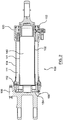
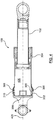
- the actuator assembly 100 shown in Figures 1 and 2 includes a cylindrical piston rod assembly 102 that moves within an interior 106 of a cylindrical housing assembly 104 between an extended position and a retracted position.
- the cylindrical housing assembly 104 has a closed end 154 and an open end 152.
- the cylindrical piston rod assembly 102 has a middle portion 140 between a first end 112 and a second end 120.
- the first end 112 of the piston rod assembly 102 is proximal to the closed end 154 of the cylindrical housing assembly 104, when the piston rod assembly 102 is located within the cylindrical housing assembly 104, while the second end 120 is distal to the closed end 154 of the cylindrical housing assembly 104.
- the piston rod assembly 102 When the piston rod assembly 102 is in the extended position, the piston rod assembly 102 extends part way out of the open end 152 of the cylindrical housing assembly 104.
- a first fluid chamber 110 is defined in the interior 106 of the cylindrical housing assembly 104, by the top surface 180 of the first end 112 of the piston rod assembly 102 and the cylindrical housing assembly 104.
- a second fluid chamber 111 is defined in the interior 106 of the cylindrical housing assembly 104 between the outer surface 141 of the middle portion 140 of the cylindrical piston rod assembly 102 and the cylindrical housing assembly 104.
- a manifold 108 is connected to the cylindrical housing assembly 104 and is fluidly connected to the fluid chambers 110, 111 located in the interior 106 of the cylindrical housing assembly 104 for allowing fluid and/or gas to enter and/or exit the interior 106.
- the manifold 108 provides routing of fluid entering or exiting the first fluid chamber 110 (e.g. through a tube, pipe or other passage).
- first fluid chamber 110 e.g. through a tube, pipe or other passage.
- a corresponding force is exerted on the first end 112 of the cylindrical piston rod assembly 102 thus extending the piston rod assembly 102 outwardly from the cylindrical housing assembly 104 into the extended position.
- the extended position is shown in Figure 1 , for example.
- the piston rod assembly 102 is forced towards the closed end 154 of the cylindrical housing assembly 104, thus moving the piston rod assembly 102 into the retracted position.
- the retracted position is shown in Figure 2 , for example.
- the piston rod assembly 102 forms a seal together with the cylindrical housing assembly 104 so that the pressure in the first fluid chamber 110 is not lost through gas or fluid leaking between the piston rod assembly 102 and the cylindrical housing assembly 104.
- This seal is formed with the assistance of one or more piston rings 114 which circumnavigates the piston rod assembly 102 and engages with the cylindrical housing assembly 104 thereby forming a seal with the cylindrical housing assembly 104.
- piston rod assembly 102 mechanisms may be familiar to persons of ordinary skill in the art. It will be understood that this description is provided as an example only.
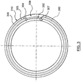
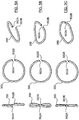
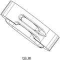
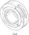
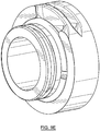
- FIG 3 is a cross sectional view of an inner component 304, removably attached to an outer component 306 using a retention wire 350. Further detail is illustrated in Figures 9A-E .
- the outer component 306 has an internal surface 305.
- the inner component 304 is sized to fit into the interior of the outer component 306 so that an outer surface 302 of the inner component 304 abuts the inner surface 305 of the outer component 306.
- a semi-circle notch circumnavigates the interior surface 305 of the outer component 306 around its longitudinal axis, indicated in Figure 4 at 420.
- a similar semi-circular notch circumnavigates the outer surface 302 of the inner component 304.
- a tangential slot 308 in the outer component 306 connects the groove in the outer component 306 with the exterior surface 310 of the outer component 306.
- a tangential slot 308 can pass from the notch on the outer surface 302 of the inner component 304 through the inner component 304 to an interior cavity of the inner component 304.
- the exterior surface 302 of the inner component 304 abuts the interior surface 305 of the outer component 306.
- the notch in the inner component 304 aligns with the notch in the outer component 306 to form a circular groove.
- the two notches align to form a circular groove that is sized to receive the retention wire 350.
- FIG. 3 illustrates that one end of retention wire 350 can have a hook end 307.
- Figure 1 illustrates one example of the use of retention wires 350 in a piston assembly.
- the inner component may be the cylindrical housing assembly 104 and the outer component may be the closed end of the cylindrical housing 154. Additional uses of the retention wires 350 will be described further below in reference to the modular piston described herein and Figures 6 and 7 .
- FIGs 5A, 5B and 5C each show a different embodiment of the retention wire 350.
- the retention wire 350 has a first end 502A and a second end 502B and is bent in a generally circular shape.
- the circular shape is such that there is a gap between the first end 502A and the second end 502B.
- the retention wire 350 can be formed in a helical ring such as a offset circular shape ( Figure 5A ), a ring having a wavy or sinusoidal profile ( Figure 5B-C ) or a circular shape with a multi-sinusoidal profile having more than one period ( Figure 5C ).
- Figure 5 includes three kinds of retention wires that prevent free play for progressively higher loads.
- There is also one retention wire that does not prevent free play which is a circular wire without an offset in the profile; a planar ring.
- a planar ring is preferably used in lower load applications and where the load is always in one direction, like between the lug end and the housing (where the load is radially outward).
- Retention wires 350 preferably have a circular cross-section.
- Two planar rings can also be installed in back-to-back grooves to reduce free play and distribute the load between both rings.
- Different shaped retention wires 350 can provide an axial force or resistance along the longitudinal axis 420, shown in Figure 4 , of the components 304, 306.
- the retention wires 350 illustrated in Figures 5A-C can be described as substantially circular.
- the retention wires 350 shown in Figures 5A-C can provide a spring cushion reaction to forces along the longitudinal axis 420. In this manner, the retention wire 350 limits or prevents free play (or relative movement) of the connected components 304, 306 under load.
- a circular wire without an offset would allow free play (e.g. similar to 5A but planar with no offset in the profile).
- Retention wires 350 are formed from a resilient material.
- the first end 502A of the retention wire 350 is received in the tangential slot 308 in the outer component 306.
- the retention wire 350 is pushed against the inner component 304.
- the inner component 304 is then rotated around the longitudinal axis 420 thereby pulling the retention wire 350 into the groove between the inner component 304 and outer component 306.
- the inner component 304 is inhibited from moving in the longitudinal direction 420 relative to the outer component 306.
- the retention wire 350 can also be removed through the tangential slot 308 to detach the inner component 304 and outer component 306.
- the tangential slot 308 can be in the inner component 304 rather than the outer component 306 so that the hook end 307 of the retention wire 350 is inserted into the tangential slot 308 through the inner component 304 rather than through the outer component 306.
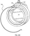
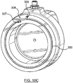
- Figures 10A-C illustrate the installation procedure of retention wire 350.
- the retention wire 350 is introduced through the tangential slot 308 in the outer component.
- Figure 10 A illustrates hook end 307 placed into a slot in the inner component through the tangential slot 308.
- the retention wire 350 can be pushed or pulled into the cavity formed by the half grooves in the inner and outer components.
- the inner component can rotate to pull the retention wire 350 into the cavity.
- the retention wire is then pushed/pulled into the cavity until the wire lies entirely along the circumferential groove in the inner component.
- Figure 10C illustrates the installed retention wire 350.
- retention wire 350 can include a second hook end 309 that can be used for removal of the retention wire 350.
- a hook end 307 can be located at the first end 502A of the retention wire 350.
- the hook is designed to latch onto the inner component 304 when the retention wire 350 is inserted into the slot 308 to ensure that the retention wire 350 will move into the groove when the inner component 304 is rotated relative to the outer component 306.
- the grooves that accept the retention wires 350 may have a non-circular form.
- the retention wire connections can allow large, complex components to be divided into several smaller components of reduced complexity thereby allowing for the modular actuator described herein, and discussed further below.
- the retention wires may be formed of any material suitable for the application within which they are being used, i.e. actuators and preferably actuators in aerospace applications, having a high spring characteristic. Examples of such materials include, but are not limited to steel and titanium.
- Figures 6 and 7 show the interior of a modular linear actuator 600 according to one embodiment of the present invention.
- the modular linear actuator 600 comprises a cylindrical housing assembly 104 having a closed end 154 and an open end 152.
- the cylindrical housing assembly 104 houses a piston rod assembly 102.
- the piston rod assembly 102 is linearly slideable within the interior of the cylindrical housing assembly 104 between an extended position and a compressed position.
- the piston rod assembly 102 has a first end 112 proximal to the closed end 154 of the cylindrical housing assembly 104 and a second end 120 distal to the closed end 154 of the cylindrical housing assembly 104, when the piston rod assembly 102 is located within the cylindrical housing assembly 104.
- a piston head 649 is removably attached to the first end 112 of the piston rod 102.
- the piston head 649 has an extension 641 that is received on and surrounds a portion of the first end 112 of the piston rod assembly 102.
- a contact seal 650 extends radially outwardly from the extension 641 and forms a seal with the gland cavity 630.
- the piston head 649 provides snubbing engagements with each of the closed end 154 and open end 152 of the cylindrical housing assembly 104 when the piston rod assembly 102 is in the compressed and extended positions, respectively.
- the piston head 649 extends from the end of the piston rod assembly 102 and abuts the inner side wall of the cylindrical housing assembly 104 thereby separating two sealed pressure vessels: the first chamber 110 and the second chamber 111.
- the first chamber 110 is defined at least by the piston head 649 and the closed end 154 of the cylindrical housing assembly 104.
- the second chamber 111 is defined at least by the piston rod assembly 102, the piston head 649 and a gland 632 at the open end of the cylindrical housing assembly 104.
- a first attachment mechanism 350 removably attaches several components in the actuator to each other.
- at least one attachment mechanism 350 removably connects a lug end 602 to an exterior of the cylindrical housing assembly 104.
- the lug end 602 attaches the actuator 600 to a first component.
- at least one attachment mechanism 350 removably attaches a rod end 604 to the second end 120 of the piston rod assembly 102.
- two attachment mechanisms 350 are shown connecting these two components.
- the rod end 604 is for attaching the piston rod assembly 102 to a second component.
- the operation of the actuator 600 moves the piston rod assembly 102 between a compressed position and an extended position thereby oscillating the rod end 604 relative to the lug end 602 causing the second component (which is attached to the rod end 604) to move relative to the first component (which is attached to the lug end 602).
- the use of the attachment mechanisms, or retention wires, allows for movement of these components while reducing, or preventing, free play between the attached components.
- the lug end 602 further defines a cavity 633 for receiving the piston head 649.
- the interaction of the piston head 649 and the cavity 633 will be described further below with reference to Figure 7 .
- a hydraulic fitting 614 is attached to the lug end 602.
- a hydraulic banjo fitting 612 is attached to the cylindrical housing assembly 104 near the open end 152 of the cylindrical housing assembly 104.
- the hydraulic fitting 614 and the hydraulic banjo fitting 612 are fluidly connected via a transfer tube 610.
- the transfer tube 610 includes a passage that allows fluid to flow from the hydraulic fitting 614 to the hydraulic banjo fitting 612.
- a passageway 109 fluidly connects the cavity 633 to the hydraulic fitting 614 and to the transfer tube 610.
- the hydraulic fitting 614 is not fluidly connected to the hydraulic banjo fitting 612.
- the hydraulic banjo fitting 612 is a separate bolt-on hydraulic fitting.
- the hydraulic fitting 614 can be a separate bolt-on hydraulic fitting.
- Rubber boots 606 are attached over each mechanical connection for protecting the mechanical connection from corrosion and abrasion.
- the rubber boots 606 can prevent or inhibit dust, dirt or other environmental contaminants from entering into the mechanical connections (e.g. the retention wire 350 attachments) thereby protecting the internal surfaces of the parts of the actuator 600 at the attachment locations from corrosion and abrasion.
- each rubber boot 606 forms an air-tight seal over the respective mechanical connection.
- a rubber boot 606 covers the connection between the lug end 602 and the closed end 154 of the cylindrical housing assembly 104.
- Another rubber boot 606 covers a portion of the open end 152 of the cylindrical housing assembly 104.
- a rubber boot 606 also covers the connection between the piston rod assembly 102 and the rod end 604.
- a gland 632 is attached to the interior 106 of the cylindrical housing assembly 104 proximal the open end 152 of the cylindrical housing assembly 104.
- the gland 632 has a central opening that is sized to allow the piston rod 102 to pass through it.
- the gland 632 forms seals against the cylindrical housing assembly 104 and against the piston rod assembly 102.
- a portion of the gland 632 facing the interior 106 of the cylindrical housing assembly 104 together with the piston rod assembly 102 define a gland cavity 630.
- An orifice or gland passage 690 fluidly connects the gland cavity 630 to the transfer tube 610 through the hydraulic banjo fitting 612.
- the gland passage 690 also connects the chamber 110 to the transfer tube 610 through the hydraulic banjo fitting 612.
- the piston head 649 is removably attached to the piston rod assembly 102.
- a retention plate 670 removably secures a spear 640 to the piston head 649, as clearly shown in Figure 7 .
- a flow control device 620 is contained inside an internal channel 623 inside the spear 640.
- the spear containing the flow control devices 620 is also referred to as a floating plunger.
- the spear 640 extends from the piston head 649 to a distal end 682.
- the passages 622 fluidly connect the first fluid chamber 110 to an internal channel 623 containing the flow control device 620 inside the spear 640.
- the internal channel 623 is also fluidly connected to the cavity 633. Fluid flowing through the internal channel 623 passes through the flow control device 620 between the first fluid chamber 110 and the cavity 633.
- the spear 640 slideably and sealably engages with the lug end 602 between a discharged position and an initial position.
- a contact seal 650 circumnavigates the spear 640 between the passages 622 and the distal end 682 forming a seal with the lug end 602 when the piston head 649 is received in the cavity 633.
- the retention plate 670 connecting the spear 640 to the piston head 649, can be secured to the piston head 649 using a nut and bolt or by other mechanisms such as a threaded connection, swaging, cir-clip, for example.
- the spear 640 may be integral with the piston head 649 such that the spear 640 forms part of the piston head 649.
- the piston head 649 together with the spear 640 form a floating plunger.
- the extension 641, of the piston head 649 fits snugly into the gland cavity 630 so that the contact seal 650 on the extension 641 forms a seal against the wall of the gland cavity 630, not shown.
- the spear 640 is separated from and disengaged from the lug end 602 so that the cavity 633 and the chamber 110 are directly fluidly connected. For example, hydraulic fluid can flow through the passageway 109, through the cavity 633 and into the chamber 110 and vice versa without passing through the spear 640.
- the spear 640 engages with the lug end 602 and the distal end 682 of the spear 640 is distal to the lug end 602, as shown in Figure 7 .
- the contact seal 650 forms a seal with the lug end 602 thereby fluidly sealing the cavity 633 from the chamber 110.
- the fluid e.g. hydraulic fluid
- the contact seal 650 maintains the seal with the lug end 602.
- the use of the flow control device 620 and the contact seal 650 allows greater control of the snubbing performance without requiring very precise tolerances to manufacture the spear 640 and cavity 633.
- the snubbing arrangement is used with the modular retention wire design allows for the use of less precise/greater tolerances when using the retention wires. This also avoids drilling holes into the cylinder because the pressures experienced are too high ( ⁇ 345 Bar ( ⁇ 5000 psi) range) for drilled holes.
- the flow control device 620 controls the rate at which the fluid flows between the passage 622 and through the channel 623 in which the flow control device 620 is located. Therefore, when the spear 640 is slideably and sealably engaged with the lug end 602 (e.g. when sliding between the initial position and the discharge position) the flow of fluid out of the chamber 110 is completely controlled by the flow control device 620.
- an extension flow control device 620 is located inside the piston head 649, shown in Figure 8 , and passages fluidly connect the chamber 110 to the cavity 633 through the piston head 649.
- the spear 640 would include a fluid passage 623 that would be in fluid communication with the passage within the piston head 649 in which the flow control device 620 would be located and passages 622 would not be present. Additional fluid passages will be located within the piston head 649 to allow for flow of fluid from the chamber 110 into the piston head 649 and through the flow control device 620. An example of one location for such a fluid passage is indicated at 822, however it will be understood that the location of the passage is not limited to this position.
- the retention wire 350 forms a mechanical connection that has free play, or relative movement of fastened components under load.
- the retention wire 350 connection can introduce a spring load or resisting axial force between the fastened components that is sufficient to resist anticipated applied loads preventing the free play that would otherwise be present.
- the retention wires illustrated in 5A to 5C prevent free play because of the axial force provided by the waves (or offset in the case of 5A) in the wire.
- the three wires are designed for progressively higher loads in the actuator to prevent free play depending on the load experienced in that area. It depends on the applications and the requirements.
- These retention wires 350 employ an arrangement that compensates for the free play between the connected elements of the actuator 600 and within the component(s) that the actuator 600 operates on (e.g. the first component and the second component). This compensation prevents backlash in the actuator 600 motion (i.e. when the actuator 600 oscillates between the compressed and extended positions). Without this type of compensation, the backlash in the actuator 600 can cause undampened, destructive oscillatory motion of the component(s) controlled by the actuator 600.
- the retention wires 350 are formed in shapes that provide an axial force along the longitudinal axis of the piston rod assembly 102.
- the retention wires 350 are in helical shapes (as shown in Figure 5A ) or have one or more waves offset from the plane of the wire 350 (as shown in Figures 5B-C ).
- the pitch of the helix can be chosen to provide the required axial force and limit installation torque.
- two retention wires 350 can be co-located to attach the extension 641 to the piston rod assembly 102.
- two retention wires 350 can be co-located to attach the rod end 604 to the piston rod assembly 102.
- either or both of the piston head 649 and gland 632 are attached with a conventional retaining ring and nut arrangement.
- the rod end 604 can be integral to the piston rod assembly 102 or can be attached using a threaded connection.
- the piston head 649 and spear 640 push the hydraulic fluid from the chamber 110 and cavity 633 into the passageway 109, which is fluidly connected to the transfer tube 610, thereby pushing the hydraulic fluid towards the hydraulic banjo fitting 612.
- the spear 640 will engage with the lug end 602, and more particularly will be received within cavity 633, and the contact seal 650 circumnavigating the spear 640 will form a seal with the lug end 602 thus defining the initial position of the spear 640.
- the hydraulic fluid is then only able to pass into the cavity 633 from the chamber 110 through the passage 622 and through the flow control device 620 and then the discharge passage 623.
- the piston rod assembly 102 and hence the spear 640 continue to move towards the lug end 602 until the compressed position is reached (also defined as the discharge position of the spear 640) with the fluid passing from the chamber 110 only through the flow control device 620.
- the flow control device 620 controls the rate of fluid flow.
- the flow control device 620 controls the rate at which the fluid flows between the passage 622 and the discharge passage 623. Therefore, as the spear 640 moves from the initial position to the discharge position, the fluid flow from the chamber 110 (and hence the hydraulic pressure of the fluid in the chamber 110) is precisely controlled using the flow control device 620 resulting in a precise snubbing operation.
- the flow control device 620 slows fluid flow during the snubbing stages of extension and compression to ensure precise timing and snubbing.
- the flow control device 620 is a sharp orifice or visco jet flow control device. The size of the orifice is selected to give the desired reduction in piston rod assembly 102 velocity.
- the flow control device 620 can, for example, be a commercial flow control device.
- the contact seal 650 ensures that there is no secondary flow around the spear 640 (or piston head 649).
Landscapes
- Engineering & Computer Science (AREA)
- General Engineering & Computer Science (AREA)
- Mechanical Engineering (AREA)
- Physics & Mathematics (AREA)
- Fluid Mechanics (AREA)
- Chemical & Material Sciences (AREA)
- Combustion & Propulsion (AREA)
- Actuator (AREA)
Claims (14)
- Actionneur linéaire modulaire (600), comprenant :un logement de piston (104) ayant une extrémité fermée (154) et une extrémité ouverte (152) ;une tige de piston (102) qui peut coulisser dans un intérieur (106) du logement de piston (104) entre une position étendue et une position compressée, la tige de piston (102) ayant une première extrémité (112) proximale par rapport à l'extrémité fermée (154) du logement de piston (104) et une seconde extrémité (120) distale par rapport à l'extrémité fermée (154) du logement de piston (104) ;un fil de rétention (350) destiné à relier de manière amovible un élément d'extrémité (602) à l'extrémité fermée (154) du logement de piston (104) ; etune tête de piston (649) reliée à la première extrémité (112) de la tige de piston (102), la tête de piston (649) pouvant assurer un engagement avec retenue avec l'élément d'extrémité (602),dans lequel la tête de piston (649) et l'extrémité fermée (154) du logement de piston (104) définissent une première chambre (110) destinée à contenir un fluide hydraulique entre elles, et la tête de piston (649) et l'extrémité ouverte (152) du logement de piston (104) définissent une seconde chambre (11) destinée à contenir un fluide hydraulique entre elles, caractérisé en ce que ledit élément d'extrémité (602) est un talon (602) et ladite tête de piston (649) comprend un dispositif de régulation de débit (620) destiné à assurer l'engagement avec retenue dans la position compressée en contrôlant le débit du fluide hydraulique dans la première chambre (110) de façon à réguler la pression dans la première chambre (110) par rapport à la pression dans la seconde chambre (111).
- Actionneur linéaire modulaire (600) selon la revendication 1, dans lequel une première encoche circonférentielle sur une surface interne du talon (602) s'aligne avec une seconde encoche circonférentielle sur une surface externe de l'extrémité fermée (154) du logement de piston (104) afin de recevoir le fil de rétention (350), dans lequel, de préférence, le talon (602) définit une fente tangentielle (308) qui relie une surface externe du talon (602) à la première encoche circonférentielle du talon (602), la fente tangentielle (308) étant destinée à insérer et retirer le fil de rétention (350) afin de fixer ou de détacher le talon (602) sur l'extrémité fermée (154) du logement de piston (14), dans lequel, de préférence, le fil de rétention (350) comprend en outre un crochet (307) destiné à se bloquer sur la surface externe de l'extrémité fermée (154) du logement de piston (104).
- Actionneur linéaire modulaire (600) selon la revendication 1, dans lequel le talon (602) est relié de manière amovible au logement de piston (104) à l'aide d'un second fil de rétention (350).
- Actionneur linéaire modulaire (600) selon la revendication 1, dans lequel la tête de piston (649) est reliée de manière amovible à la première extrémité (112) de la tige de piston (102) à l'aide d'un second fil de rétention (350).
- Actionneur linéaire modulaire (600) selon la revendication 4, dans lequel un quelconque du premier fil de rétention (350) et du second fil de rétention (350) est formé comme une hélice afin de fournir une force axiale dans la direction de l'axe longitudinal de la tige de piston (102) de façon à compenser le jeu libre entre la tige de piston (102) et l'extrémité de tige.
- Actionneur linéaire modulaire (600) selon la revendication 4, dans lequel un quelconque du premier fil de rétention (350) et du second fil de rétention (350) comprend au moins une vague destinée à fournir une force entre la tige de piston (102) et l'extrémité de tige de façon à compenser le jeu libre entre la tige de piston (102) et la tige.
- Actionneur linéaire modulaire (600) selon la revendication 1, dans lequel la tête de piston (649) comprend en outre une saillie (640) qui s'étend depuis la tête de piston (649) dans la première chambre (110), et le talon (602) définit une cavité (633) qui s'engage de manière étanche avec la saillie (640) dans la position compressée afin d'orienter le fluide hydraulique vers le dispositif de régulation de débit (620), dans lequel, de préférence, la saillie (640) comprend en outre un joint de contact (650) qui réengage dynamiquement la cavité (633), dans lequel, de préférence, la saillie (640) est reliée à la tête de piston (649) à l'aide d'une plaque de rétention (670).
- Actionneur linéaire modulaire (600) selon la revendication 7, comprenant en outre un presse-étoupe (632) relié de manière amovible à l'extrémité ouverte (152) du logement de piston (104), le presse-étoupe (632) définissant une cavité de presse-étoupe (630) qui s'ouvre dans la seconde chambre (111), la tête de piston (649) comprenant en outre une extension de tête de piston (641) qui engage de manière étanche la cavité de presse-étoupe (630) dans la position étendue, le presse-étoupe (632) comprenant en outre un second dispositif de régulation de débit (620) relié à la cavité de presse-étoupe (630) afin d'assurer l'engagement avec retenue dans la position étendue en régulant le débit du fluide hydraulique depuis la cavité de presse-étoupe (630).
- Actionneur linéaire modulaire (600) selon la revendication 8, dans lequel l'extension de tête de piston (641) comprend en outre un joint de contact (650) qui réengage dynamiquement la cavité de presse-étoupe (630).
- Actionneur linéaire modulaire (600) selon la revendication 8, comprenant en outre un raccord hydraulique fixé près de l'extrémité ouverte (152) du logement de piston (104) et relié à la cavité de presse-étoupe (630).
- Actionneur linéaire modulaire (600) selon la revendication 8, dans lequel le presse-étoupe (632) est relié de manière amovible à l'extrémité ouverte (152) du logement de piston (104) par un second fil de rétention (350).
- Actionneur linéaire modulaire (600) selon l'une quelconque des revendications 1 à 12, dans lequel le fil de rétention (350) comprend : un fil flexible allongé ayant deux extrémités libres (502A, 502B), le fil formant une forme sensiblement circulaire sur un premier plan et comprenant une ou plusieurs vague(s) espacée(s) le long du fil, les vagues s'étendant sur un second plan.
- Actionneur linéaire modulaire (600) selon la revendication 12, dans lequel la ou les vague(s) dans le fil de rétention (350) forment un motif sinusoïdal le long du fil, dans lequel, de préférence, les vagues forment un motif hélicoïdal sur le second plan.
- Actionneur linéaire modulaire (600) selon la revendication 12, dans lequel les extrémités libres (502A, 502B) du fil de rétention (350) sont décalées l'une par rapport à l'autre.
Applications Claiming Priority (2)
| Application Number | Priority Date | Filing Date | Title |
|---|---|---|---|
| US201361764292P | 2013-02-13 | 2013-02-13 | |
| PCT/CA2014/000105 WO2014124519A1 (fr) | 2013-02-13 | 2014-02-13 | Actionneur modulaire à agencement de retenue |
Publications (3)
| Publication Number | Publication Date |
|---|---|
| EP2956679A1 EP2956679A1 (fr) | 2015-12-23 |
| EP2956679A4 EP2956679A4 (fr) | 2017-03-29 |
| EP2956679B1 true EP2956679B1 (fr) | 2020-04-29 |
Family
ID=51353445
Family Applications (1)
| Application Number | Title | Priority Date | Filing Date |
|---|---|---|---|
| EP14751849.2A Active EP2956679B1 (fr) | 2013-02-13 | 2014-02-13 | Actionneur modulaire à agencement de retenue |
Country Status (5)
| Country | Link |
|---|---|
| US (1) | US10151333B2 (fr) |
| EP (1) | EP2956679B1 (fr) |
| CN (1) | CN105121867B (fr) |
| CA (1) | CA2900787C (fr) |
| WO (1) | WO2014124519A1 (fr) |
Families Citing this family (19)
| Publication number | Priority date | Publication date | Assignee | Title |
|---|---|---|---|---|
| CN107002665B (zh) | 2014-12-30 | 2019-11-29 | 固瑞克明尼苏达有限公司 | 轴向往复泵上的一体式安装系统 |
| WO2016166964A1 (fr) * | 2015-04-17 | 2016-10-20 | Smc Corporation | Cylindre à pression de fluide |
| JP6524471B2 (ja) * | 2015-04-17 | 2019-06-05 | Smc株式会社 | 流体圧シリンダ |
| US10066649B2 (en) * | 2015-10-13 | 2018-09-04 | Goodrich Corporation | Hybrid metallic/composite piston head joint |
| JP6255440B2 (ja) * | 2016-03-31 | 2017-12-27 | Kyb株式会社 | 流体圧シリンダ |
| DE102016107393A1 (de) * | 2016-04-21 | 2017-10-26 | Festo Ag & Co. Kg | Modulares Antriebssystem |
| BR102018003284B1 (pt) | 2017-02-21 | 2021-07-20 | Graco Minnesota Inc. | Haste de pistão para uma bomba, bomba, pulverizador, e, método para substituir uma luva de desgaste |
| CN107654441B (zh) * | 2017-10-25 | 2024-04-16 | 中国第一汽车股份有限公司 | 一种同步器换档气缸 |
| DE102019108451B3 (de) * | 2019-04-01 | 2020-07-02 | Schwing Gmbh | Kolbenstangen-Einheit, Hydraulikzylinder und Knickmast |
| GB2587193A (en) * | 2019-09-13 | 2021-03-24 | Airbus Operations Ltd | Aircraft landing gear system |
| CN115335601A (zh) | 2020-03-31 | 2022-11-11 | 固瑞克明尼苏达有限公司 | 用于多组分喷涂系统的电操作泵 |
| EP4596881A3 (fr) | 2020-03-31 | 2025-08-13 | Graco Minnesota Inc. | Pompe linéaire à commande électrique |
| EP4127474B1 (fr) | 2020-03-31 | 2025-03-12 | Graco Minnesota Inc. | Système d'entraînement de pompe |
| DE102020005538B4 (de) * | 2020-09-10 | 2023-01-12 | Günther Zimmer | Schichtmodul für Handhabungsrobotersystem |
| WO2022204011A1 (fr) * | 2021-03-23 | 2022-09-29 | Caterpillar Inc. | Agencement de retenue d'amortissement de cylindre hydraulique |
| US11319972B1 (en) * | 2021-05-11 | 2022-05-03 | Caterpillar Inc. | Hydraulic cylinder snubbing retention arrangement |
| US20230027763A1 (en) * | 2021-07-21 | 2023-01-26 | Fox Factory, Inc. | Internal floating piston |
| JP2024126182A (ja) * | 2023-03-07 | 2024-09-20 | キャタピラー エス エー アール エル | 流体圧シリンダの駆動制御装置 |
| US12276289B1 (en) * | 2024-05-10 | 2025-04-15 | Mark Pelini | Hydraulic cylinder top end cap |
Family Cites Families (30)
| Publication number | Priority date | Publication date | Assignee | Title |
|---|---|---|---|---|
| US2493602A (en) * | 1947-12-31 | 1950-01-03 | Vance C Sterrett | Pressure fluid motor |
| US2952480A (en) * | 1956-10-22 | 1960-09-13 | Beckman Instruments Inc | Fastening device detachably coupling grooved cylindrical surfaces |
| US3704650A (en) * | 1971-03-29 | 1972-12-05 | Caterpillar Tractor Co | Hydraulic jack stroke cushioning means |
| SU436933A2 (ru) * | 1973-02-19 | 1974-07-25 | Завод "Ташсельмаш" Им.К.Е.Ворошилова | Устройство для фиксации |
| US4048905A (en) * | 1976-03-29 | 1977-09-20 | The Boeing Company | Variable orifice hydraulic snubber |
| US4167134A (en) * | 1977-02-28 | 1979-09-11 | Yuda Lawrence F | Compact fluid actuator |
| US4192225A (en) * | 1978-02-10 | 1980-03-11 | The Cessna Aircraft Company | Cylinder locking ring |
| US4296675A (en) * | 1979-07-16 | 1981-10-27 | Aeroquip Corporation | Cylinder cushion with contractable ring |
| NZ202076A (en) * | 1982-10-04 | 1986-06-11 | Campion & Irving Ltd | Retention of first member in bore of second member using grooves and retaining rings |
| DE3419263A1 (de) * | 1984-05-23 | 1985-11-28 | Ing. Lang & Menke Gmbh, 5870 Hemer | Federring, insbesondere fuer kugellager oder wellen |
| DE3635020C2 (de) * | 1985-10-26 | 1994-08-04 | Volkswagen Ag | Formschlüssige Befestigung einer axialkraftbeaufschlagten kreiszylindrischen Anschlagscheibe in einem Zylinder |
| US4771678A (en) * | 1986-06-09 | 1988-09-20 | Prince Manufacturing Corporation | Piston locking device for double acting hydraulic cylinder |
| US4752178A (en) * | 1986-12-17 | 1988-06-21 | Smalley Steel Ring Company | Waved retaining ring |
| US4878419A (en) * | 1988-06-27 | 1989-11-07 | Allied-Signal Inc. | Lightweight hydraulic actuator |
| US5286135A (en) * | 1990-09-28 | 1994-02-15 | Martin Marietta Corporation | Joinder of separable tubular structures utilizing preloaded O-ring |
| US5357847A (en) * | 1991-04-17 | 1994-10-25 | Hytork Actuators Limited | Pressure vessels having end closures and retainers |
| US5400695A (en) * | 1994-03-08 | 1995-03-28 | Prince Manufacturing Corporation | Method and device for locking cylindrical members together |
| KR0166223B1 (ko) * | 1995-03-29 | 1998-12-01 | 서상기 | 공압실린더 |
| US5720368A (en) | 1997-03-03 | 1998-02-24 | Caterpillar Inc. | Snubber for a hydraulic cylinder |
| GB9709621D0 (en) * | 1997-05-13 | 1997-07-02 | Hytek Tech Int | Pressure vessels |
| US6101922A (en) * | 1998-04-21 | 2000-08-15 | Jeffrey R. King | Cylinder |
| DE19836422C2 (de) * | 1998-08-12 | 2002-10-24 | Mannesmann Rexroth Ag | Druckmittelbetätigter Arbeitszylinder |
| DE19843253C2 (de) * | 1998-09-10 | 2002-07-25 | Rexroth Mecman Gmbh | Druckmittelzylinder mit einem Zylinderrohr |
| DE10162527A1 (de) * | 2001-12-19 | 2003-07-10 | Rexroth Mecman Gmbh | Druckmittelzylinder mit einem formschlüssig befestigten Zylinderdeckel |
| JP2004293628A (ja) * | 2003-03-26 | 2004-10-21 | Kayaba Ind Co Ltd | 液圧シリンダの制御装置 |
| CN101178085A (zh) * | 2007-11-28 | 2008-05-14 | 浙江工业大学 | 一种可控行程气缸 |
| US7967116B2 (en) * | 2007-12-10 | 2011-06-28 | Enidine, Inc. | Load compensating hydraulic rate control |
| CN201412414Y (zh) * | 2009-06-17 | 2010-02-24 | 江苏恒立高压油缸有限公司 | 油缸导向套防松装置 |
| CN202132304U (zh) * | 2011-07-29 | 2012-02-01 | 合肥长源液压股份有限公司 | 无杆腔内设有组合式缓冲装置的高压油缸 |
| CN102889265A (zh) * | 2012-10-18 | 2013-01-23 | 徐州永佳液压设备有限公司 | 一种具有磁力缓冲结构的液压油缸 |
-
2014
- 2014-02-13 CA CA2900787A patent/CA2900787C/fr active Active
- 2014-02-13 US US14/767,556 patent/US10151333B2/en active Active
- 2014-02-13 EP EP14751849.2A patent/EP2956679B1/fr active Active
- 2014-02-13 CN CN201480022011.8A patent/CN105121867B/zh active Active
- 2014-02-13 WO PCT/CA2014/000105 patent/WO2014124519A1/fr not_active Ceased
Also Published As
| Publication number | Publication date |
|---|---|
| WO2014124519A1 (fr) | 2014-08-21 |
| US20150377262A1 (en) | 2015-12-31 |
| EP2956679A4 (fr) | 2017-03-29 |
| CN105121867B (zh) | 2018-02-27 |
| CN105121867A (zh) | 2015-12-02 |
| CA2900787A1 (fr) | 2014-08-21 |
| EP2956679A1 (fr) | 2015-12-23 |
| CA2900787C (fr) | 2020-02-25 |
| US10151333B2 (en) | 2018-12-11 |
Similar Documents
| Publication | Publication Date | Title |
|---|---|---|
| US10151333B2 (en) | Modular actuator with snubbing arrangement | |
| US8678350B2 (en) | Valve and method for controlling flow in tubular members | |
| EP2951444B1 (fr) | Mécanisme de blocage pour bloquer un actionneur | |
| RU2672235C2 (ru) | Устройство исполнительного привода с внутренней трубкой и механизмом блокировки вращения | |
| EP3569891A1 (fr) | Amortisseur hydraulique ayant un agencement d'arrêt hydraulique | |
| RU2598955C2 (ru) | Модульный скважинный инструмент | |
| CN106461112A (zh) | 阀 | |
| EP2635829B1 (fr) | Dispositif de précontrainte pour actionneur de vanne | |
| EP2839194B1 (fr) | Ensemble actionneur de soupape | |
| US20120018573A1 (en) | Compact shimmy damper for aircraft landing gear | |
| EP1686267A1 (fr) | Actionneur linéaire | |
| EP2247815A2 (fr) | Outil de réglage de direction verticale pour appareil de forage de fond de trou | |
| US7347287B2 (en) | Hydraulic timing device | |
| US20170059049A1 (en) | Pressure release valve for oil recovery systems | |
| EP2378136B1 (fr) | Vérin hydraulique | |
| EP3081820B1 (fr) | Actionneur hydraulique et son procédé de production | |
| US20110011257A1 (en) | Electro-hydraulic actuator having end cap with split bushing | |
| US6098714A (en) | Hydraulic fluid actuator with metal to metal seals | |
| WO2022006529A1 (fr) | Vanne de régulation électrique de débit | |
| US20210262494A1 (en) | Valve with Anti-Cavitation Features | |
| SA522440533B1 (ar) | نظام استبدال أطراف الصمامات وطريقة استبدالها | |
| EP3736453A1 (fr) | Cylindre à l'aide d'un dispositif de fermeture à barres | |
| US20170292579A1 (en) | Shock absorber | |
| WO2016111944A1 (fr) | Joint souple à soufflet à haute pression | |
| CN115704504A (zh) | 阀致动器、阀组件和方法 |
Legal Events
| Date | Code | Title | Description |
|---|---|---|---|
| PUAI | Public reference made under article 153(3) epc to a published international application that has entered the european phase |
Free format text: ORIGINAL CODE: 0009012 |
|
| 17P | Request for examination filed |
Effective date: 20150828 |
|
| AK | Designated contracting states |
Kind code of ref document: A1 Designated state(s): AL AT BE BG CH CY CZ DE DK EE ES FI FR GB GR HR HU IE IS IT LI LT LU LV MC MK MT NL NO PL PT RO RS SE SI SK SM TR |
|
| AX | Request for extension of the european patent |
Extension state: BA ME |
|
| DAX | Request for extension of the european patent (deleted) | ||
| RIC1 | Information provided on ipc code assigned before grant |
Ipc: F15B 15/22 20060101ALI20161012BHEP Ipc: F15B 15/14 20060101AFI20161012BHEP Ipc: F16J 1/12 20060101ALI20161012BHEP Ipc: F16J 1/00 20060101ALI20161012BHEP Ipc: F16J 1/09 20060101ALI20161012BHEP |
|
| RAP1 | Party data changed (applicant data changed or rights of an application transferred) |
Owner name: SAFRAN LANDING SYSTEMS CANADA INC. |
|
| A4 | Supplementary search report drawn up and despatched |
Effective date: 20170224 |
|
| RIC1 | Information provided on ipc code assigned before grant |
Ipc: F15B 15/22 20060101ALI20170218BHEP Ipc: F16B 3/04 20060101ALI20170218BHEP Ipc: F16J 1/00 20060101ALI20170218BHEP Ipc: F16J 1/09 20060101ALI20170218BHEP Ipc: F16J 1/12 20060101ALI20170218BHEP Ipc: F15B 15/14 20060101AFI20170218BHEP |
|
| GRAP | Despatch of communication of intention to grant a patent |
Free format text: ORIGINAL CODE: EPIDOSNIGR1 |
|
| STAA | Information on the status of an ep patent application or granted ep patent |
Free format text: STATUS: GRANT OF PATENT IS INTENDED |
|
| INTG | Intention to grant announced |
Effective date: 20191111 |
|
| GRAS | Grant fee paid |
Free format text: ORIGINAL CODE: EPIDOSNIGR3 |
|
| GRAA | (expected) grant |
Free format text: ORIGINAL CODE: 0009210 |
|
| STAA | Information on the status of an ep patent application or granted ep patent |
Free format text: STATUS: THE PATENT HAS BEEN GRANTED |
|
| AK | Designated contracting states |
Kind code of ref document: B1 Designated state(s): AL AT BE BG CH CY CZ DE DK EE ES FI FR GB GR HR HU IE IS IT LI LT LU LV MC MK MT NL NO PL PT RO RS SE SI SK SM TR |
|
| REG | Reference to a national code |
Ref country code: GB Ref legal event code: FG4D |
|
| REG | Reference to a national code |
Ref country code: CH Ref legal event code: EP |
|
| REG | Reference to a national code |
Ref country code: AT Ref legal event code: REF Ref document number: 1263742 Country of ref document: AT Kind code of ref document: T Effective date: 20200515 |
|
| REG | Reference to a national code |
Ref country code: DE Ref legal event code: R096 Ref document number: 602014064525 Country of ref document: DE |
|
| REG | Reference to a national code |
Ref country code: IE Ref legal event code: FG4D |
|
| REG | Reference to a national code |
Ref country code: NL Ref legal event code: MP Effective date: 20200429 |
|
| REG | Reference to a national code |
Ref country code: LT Ref legal event code: MG4D |
|
| PG25 | Lapsed in a contracting state [announced via postgrant information from national office to epo] |
Ref country code: GR Free format text: LAPSE BECAUSE OF FAILURE TO SUBMIT A TRANSLATION OF THE DESCRIPTION OR TO PAY THE FEE WITHIN THE PRESCRIBED TIME-LIMIT Effective date: 20200730 Ref country code: PT Free format text: LAPSE BECAUSE OF FAILURE TO SUBMIT A TRANSLATION OF THE DESCRIPTION OR TO PAY THE FEE WITHIN THE PRESCRIBED TIME-LIMIT Effective date: 20200831 Ref country code: SE Free format text: LAPSE BECAUSE OF FAILURE TO SUBMIT A TRANSLATION OF THE DESCRIPTION OR TO PAY THE FEE WITHIN THE PRESCRIBED TIME-LIMIT Effective date: 20200429 Ref country code: NO Free format text: LAPSE BECAUSE OF FAILURE TO SUBMIT A TRANSLATION OF THE DESCRIPTION OR TO PAY THE FEE WITHIN THE PRESCRIBED TIME-LIMIT Effective date: 20200729 Ref country code: IS Free format text: LAPSE BECAUSE OF FAILURE TO SUBMIT A TRANSLATION OF THE DESCRIPTION OR TO PAY THE FEE WITHIN THE PRESCRIBED TIME-LIMIT Effective date: 20200829 Ref country code: FI Free format text: LAPSE BECAUSE OF FAILURE TO SUBMIT A TRANSLATION OF THE DESCRIPTION OR TO PAY THE FEE WITHIN THE PRESCRIBED TIME-LIMIT Effective date: 20200429 Ref country code: LT Free format text: LAPSE BECAUSE OF FAILURE TO SUBMIT A TRANSLATION OF THE DESCRIPTION OR TO PAY THE FEE WITHIN THE PRESCRIBED TIME-LIMIT Effective date: 20200429 |
|
| REG | Reference to a national code |
Ref country code: AT Ref legal event code: MK05 Ref document number: 1263742 Country of ref document: AT Kind code of ref document: T Effective date: 20200429 |
|
| PG25 | Lapsed in a contracting state [announced via postgrant information from national office to epo] |
Ref country code: LV Free format text: LAPSE BECAUSE OF FAILURE TO SUBMIT A TRANSLATION OF THE DESCRIPTION OR TO PAY THE FEE WITHIN THE PRESCRIBED TIME-LIMIT Effective date: 20200429 Ref country code: BG Free format text: LAPSE BECAUSE OF FAILURE TO SUBMIT A TRANSLATION OF THE DESCRIPTION OR TO PAY THE FEE WITHIN THE PRESCRIBED TIME-LIMIT Effective date: 20200729 Ref country code: RS Free format text: LAPSE BECAUSE OF FAILURE TO SUBMIT A TRANSLATION OF THE DESCRIPTION OR TO PAY THE FEE WITHIN THE PRESCRIBED TIME-LIMIT Effective date: 20200429 Ref country code: HR Free format text: LAPSE BECAUSE OF FAILURE TO SUBMIT A TRANSLATION OF THE DESCRIPTION OR TO PAY THE FEE WITHIN THE PRESCRIBED TIME-LIMIT Effective date: 20200429 |
|
| PG25 | Lapsed in a contracting state [announced via postgrant information from national office to epo] |
Ref country code: AL Free format text: LAPSE BECAUSE OF FAILURE TO SUBMIT A TRANSLATION OF THE DESCRIPTION OR TO PAY THE FEE WITHIN THE PRESCRIBED TIME-LIMIT Effective date: 20200429 Ref country code: NL Free format text: LAPSE BECAUSE OF FAILURE TO SUBMIT A TRANSLATION OF THE DESCRIPTION OR TO PAY THE FEE WITHIN THE PRESCRIBED TIME-LIMIT Effective date: 20200429 |
|
| PG25 | Lapsed in a contracting state [announced via postgrant information from national office to epo] |
Ref country code: ES Free format text: LAPSE BECAUSE OF FAILURE TO SUBMIT A TRANSLATION OF THE DESCRIPTION OR TO PAY THE FEE WITHIN THE PRESCRIBED TIME-LIMIT Effective date: 20200429 Ref country code: CZ Free format text: LAPSE BECAUSE OF FAILURE TO SUBMIT A TRANSLATION OF THE DESCRIPTION OR TO PAY THE FEE WITHIN THE PRESCRIBED TIME-LIMIT Effective date: 20200429 Ref country code: RO Free format text: LAPSE BECAUSE OF FAILURE TO SUBMIT A TRANSLATION OF THE DESCRIPTION OR TO PAY THE FEE WITHIN THE PRESCRIBED TIME-LIMIT Effective date: 20200429 Ref country code: AT Free format text: LAPSE BECAUSE OF FAILURE TO SUBMIT A TRANSLATION OF THE DESCRIPTION OR TO PAY THE FEE WITHIN THE PRESCRIBED TIME-LIMIT Effective date: 20200429 Ref country code: SM Free format text: LAPSE BECAUSE OF FAILURE TO SUBMIT A TRANSLATION OF THE DESCRIPTION OR TO PAY THE FEE WITHIN THE PRESCRIBED TIME-LIMIT Effective date: 20200429 Ref country code: EE Free format text: LAPSE BECAUSE OF FAILURE TO SUBMIT A TRANSLATION OF THE DESCRIPTION OR TO PAY THE FEE WITHIN THE PRESCRIBED TIME-LIMIT Effective date: 20200429 Ref country code: DK Free format text: LAPSE BECAUSE OF FAILURE TO SUBMIT A TRANSLATION OF THE DESCRIPTION OR TO PAY THE FEE WITHIN THE PRESCRIBED TIME-LIMIT Effective date: 20200429 Ref country code: IT Free format text: LAPSE BECAUSE OF FAILURE TO SUBMIT A TRANSLATION OF THE DESCRIPTION OR TO PAY THE FEE WITHIN THE PRESCRIBED TIME-LIMIT Effective date: 20200429 |
|
| REG | Reference to a national code |
Ref country code: DE Ref legal event code: R097 Ref document number: 602014064525 Country of ref document: DE |
|
| PG25 | Lapsed in a contracting state [announced via postgrant information from national office to epo] |
Ref country code: PL Free format text: LAPSE BECAUSE OF FAILURE TO SUBMIT A TRANSLATION OF THE DESCRIPTION OR TO PAY THE FEE WITHIN THE PRESCRIBED TIME-LIMIT Effective date: 20200429 Ref country code: SK Free format text: LAPSE BECAUSE OF FAILURE TO SUBMIT A TRANSLATION OF THE DESCRIPTION OR TO PAY THE FEE WITHIN THE PRESCRIBED TIME-LIMIT Effective date: 20200429 |
|
| PLBE | No opposition filed within time limit |
Free format text: ORIGINAL CODE: 0009261 |
|
| STAA | Information on the status of an ep patent application or granted ep patent |
Free format text: STATUS: NO OPPOSITION FILED WITHIN TIME LIMIT |
|
| 26N | No opposition filed |
Effective date: 20210201 |
|
| PG25 | Lapsed in a contracting state [announced via postgrant information from national office to epo] |
Ref country code: SI Free format text: LAPSE BECAUSE OF FAILURE TO SUBMIT A TRANSLATION OF THE DESCRIPTION OR TO PAY THE FEE WITHIN THE PRESCRIBED TIME-LIMIT Effective date: 20200429 |
|
| PG25 | Lapsed in a contracting state [announced via postgrant information from national office to epo] |
Ref country code: MC Free format text: LAPSE BECAUSE OF FAILURE TO SUBMIT A TRANSLATION OF THE DESCRIPTION OR TO PAY THE FEE WITHIN THE PRESCRIBED TIME-LIMIT Effective date: 20200429 |
|
| REG | Reference to a national code |
Ref country code: BE Ref legal event code: MM Effective date: 20210228 |
|
| PG25 | Lapsed in a contracting state [announced via postgrant information from national office to epo] |
Ref country code: LU Free format text: LAPSE BECAUSE OF NON-PAYMENT OF DUE FEES Effective date: 20210213 Ref country code: LI Free format text: LAPSE BECAUSE OF NON-PAYMENT OF DUE FEES Effective date: 20210228 Ref country code: CH Free format text: LAPSE BECAUSE OF NON-PAYMENT OF DUE FEES Effective date: 20210228 |
|
| PG25 | Lapsed in a contracting state [announced via postgrant information from national office to epo] |
Ref country code: IE Free format text: LAPSE BECAUSE OF NON-PAYMENT OF DUE FEES Effective date: 20210213 |
|
| PG25 | Lapsed in a contracting state [announced via postgrant information from national office to epo] |
Ref country code: BE Free format text: LAPSE BECAUSE OF NON-PAYMENT OF DUE FEES Effective date: 20210228 |
|
| PG25 | Lapsed in a contracting state [announced via postgrant information from national office to epo] |
Ref country code: HU Free format text: LAPSE BECAUSE OF FAILURE TO SUBMIT A TRANSLATION OF THE DESCRIPTION OR TO PAY THE FEE WITHIN THE PRESCRIBED TIME-LIMIT; INVALID AB INITIO Effective date: 20140213 |
|
| PG25 | Lapsed in a contracting state [announced via postgrant information from national office to epo] |
Ref country code: CY Free format text: LAPSE BECAUSE OF FAILURE TO SUBMIT A TRANSLATION OF THE DESCRIPTION OR TO PAY THE FEE WITHIN THE PRESCRIBED TIME-LIMIT Effective date: 20200429 |
|
| PG25 | Lapsed in a contracting state [announced via postgrant information from national office to epo] |
Ref country code: MK Free format text: LAPSE BECAUSE OF FAILURE TO SUBMIT A TRANSLATION OF THE DESCRIPTION OR TO PAY THE FEE WITHIN THE PRESCRIBED TIME-LIMIT Effective date: 20200429 |
|
| PG25 | Lapsed in a contracting state [announced via postgrant information from national office to epo] |
Ref country code: MT Free format text: LAPSE BECAUSE OF FAILURE TO SUBMIT A TRANSLATION OF THE DESCRIPTION OR TO PAY THE FEE WITHIN THE PRESCRIBED TIME-LIMIT Effective date: 20200429 |
|
| PG25 | Lapsed in a contracting state [announced via postgrant information from national office to epo] |
Ref country code: TR Free format text: LAPSE BECAUSE OF FAILURE TO SUBMIT A TRANSLATION OF THE DESCRIPTION OR TO PAY THE FEE WITHIN THE PRESCRIBED TIME-LIMIT Effective date: 20200429 |
|
| PGFP | Annual fee paid to national office [announced via postgrant information from national office to epo] |
Ref country code: GB Payment date: 20260219 Year of fee payment: 13 |
|
| PGFP | Annual fee paid to national office [announced via postgrant information from national office to epo] |
Ref country code: DE Payment date: 20260217 Year of fee payment: 13 |
|
| PGFP | Annual fee paid to national office [announced via postgrant information from national office to epo] |
Ref country code: FR Payment date: 20260213 Year of fee payment: 13 |