EP2956747B1 - Procédé et appareil permettant de poser et de déposer un réducteur de débit d'un dispositif de mesure de pression différentielle - Google Patents
Procédé et appareil permettant de poser et de déposer un réducteur de débit d'un dispositif de mesure de pression différentielle Download PDFInfo
- Publication number
- EP2956747B1 EP2956747B1 EP13875119.3A EP13875119A EP2956747B1 EP 2956747 B1 EP2956747 B1 EP 2956747B1 EP 13875119 A EP13875119 A EP 13875119A EP 2956747 B1 EP2956747 B1 EP 2956747B1
- Authority
- EP
- European Patent Office
- Prior art keywords
- seal
- opening
- fitting
- channel
- flow restrictor
- Prior art date
- Legal status (The legal status is an assumption and is not a legal conclusion. Google has not performed a legal analysis and makes no representation as to the accuracy of the status listed.)
- Active
Links
Images


Classifications
-
- B—PERFORMING OPERATIONS; TRANSPORTING
- B23—MACHINE TOOLS; METAL-WORKING NOT OTHERWISE PROVIDED FOR
- B23P—METAL-WORKING NOT OTHERWISE PROVIDED FOR; COMBINED OPERATIONS; UNIVERSAL MACHINE TOOLS
- B23P17/00—Metal-working operations, not covered by a single other subclass or another group in this subclass
- B23P17/04—Metal-working operations, not covered by a single other subclass or another group in this subclass characterised by the nature of the material involved or the kind of product independently of its shape
-
- G—PHYSICS
- G01—MEASURING; TESTING
- G01F—MEASURING VOLUME, VOLUME FLOW, MASS FLOW OR LIQUID LEVEL; METERING BY VOLUME
- G01F1/00—Measuring the volume flow or mass flow of fluid or fluent solid material wherein the fluid passes through a meter in a continuous flow
- G01F1/05—Measuring the volume flow or mass flow of fluid or fluent solid material wherein the fluid passes through a meter in a continuous flow by using mechanical effects
- G01F1/34—Measuring the volume flow or mass flow of fluid or fluent solid material wherein the fluid passes through a meter in a continuous flow by using mechanical effects by measuring pressure or differential pressure
- G01F1/36—Measuring the volume flow or mass flow of fluid or fluent solid material wherein the fluid passes through a meter in a continuous flow by using mechanical effects by measuring pressure or differential pressure the pressure or differential pressure being created by the use of flow constriction
- G01F1/40—Details of construction of the flow constriction devices
- G01F1/42—Orifices or nozzles
-
- G—PHYSICS
- G01—MEASURING; TESTING
- G01F—MEASURING VOLUME, VOLUME FLOW, MASS FLOW OR LIQUID LEVEL; METERING BY VOLUME
- G01F15/00—Details of, or accessories for, apparatus of groups G01F1/00 - G01F13/00 insofar as such details or appliances are not adapted to particular types of such apparatus
- G01F15/005—Valves
-
- G—PHYSICS
- G01—MEASURING; TESTING
- G01L—MEASURING FORCE, STRESS, TORQUE, WORK, MECHANICAL POWER, MECHANICAL EFFICIENCY, OR FLUID PRESSURE
- G01L13/00—Devices or apparatus for measuring differences of two or more fluid pressure values
-
- G—PHYSICS
- G01—MEASURING; TESTING
- G01F—MEASURING VOLUME, VOLUME FLOW, MASS FLOW OR LIQUID LEVEL; METERING BY VOLUME
- G01F15/00—Details of, or accessories for, apparatus of groups G01F1/00 - G01F13/00 insofar as such details or appliances are not adapted to particular types of such apparatus
- G01F15/14—Casings, e.g. of special material
-
- G—PHYSICS
- G01—MEASURING; TESTING
- G01F—MEASURING VOLUME, VOLUME FLOW, MASS FLOW OR LIQUID LEVEL; METERING BY VOLUME
- G01F15/00—Details of, or accessories for, apparatus of groups G01F1/00 - G01F13/00 insofar as such details or appliances are not adapted to particular types of such apparatus
- G01F15/18—Supports or connecting means for meters
-
- Y—GENERAL TAGGING OF NEW TECHNOLOGICAL DEVELOPMENTS; GENERAL TAGGING OF CROSS-SECTIONAL TECHNOLOGIES SPANNING OVER SEVERAL SECTIONS OF THE IPC; TECHNICAL SUBJECTS COVERED BY FORMER USPC CROSS-REFERENCE ART COLLECTIONS [XRACs] AND DIGESTS
- Y10—TECHNICAL SUBJECTS COVERED BY FORMER USPC
- Y10T—TECHNICAL SUBJECTS COVERED BY FORMER US CLASSIFICATION
- Y10T137/00—Fluid handling
- Y10T137/0318—Processes
- Y10T137/0402—Cleaning, repairing, or assembling
- Y10T137/0491—Valve or valve element assembling, disassembling, or replacing
-
- Y—GENERAL TAGGING OF NEW TECHNOLOGICAL DEVELOPMENTS; GENERAL TAGGING OF CROSS-SECTIONAL TECHNOLOGIES SPANNING OVER SEVERAL SECTIONS OF THE IPC; TECHNICAL SUBJECTS COVERED BY FORMER USPC CROSS-REFERENCE ART COLLECTIONS [XRACs] AND DIGESTS
- Y10—TECHNICAL SUBJECTS COVERED BY FORMER USPC
- Y10T—TECHNICAL SUBJECTS COVERED BY FORMER US CLASSIFICATION
- Y10T137/00—Fluid handling
- Y10T137/598—With repair, tapping, assembly, or disassembly means
- Y10T137/6109—Tool for applying or removing valve or valve member
- Y10T137/6113—Including sealing feature
Definitions
- This relates to an orifice fitting having a double block and bleed.
- Orifices plates are often used in flow lines to create a differential pressure, which is measured and used to calculate the flow rate through the pipeline. When removing the orifice plate from the flow line, care must be taken when the flow line is pressurized.
- Patent publication no. WO2012/120158 describes a device intended to allow the plate to be removed without interrupting flow through the flow line.
- GB 2319088 A describes an apparatus for installing and removing a flow restrictor from a differential pressure measurement device in a fluid channel, the apparatus comprising a fitting for receiving the flow restrictor and a receptacle for retaining the flow restrictor, using a set-up with two sealing elements for allowing to change the restrictor without interrupting the flow of the fluid.
- an apparatus for installing and removing a flow restrictor from a differential pressure measurement device comprising a fitting connected in line with a fluid line, the fitting having a fitting opening for receiving the flow restrictor and a receptacle for retaining the flow restrictor.
- the apparatus comprises a seal housing extending away from the fitting opening of the fitting, the seal housing being sealed to the fitting opening of the fitting.
- the seal housing has a housing opening spaced from the fitting opening of the fitting and a channel connecting the housing opening to the fitting opening.
- the seal housing comprises a first seal that seals the fitting opening, a second seal spaced from the first seal along the channel, and a third seal that seals the housing opening, the distance between the second seal and the third seal being greater than the height of the flow restrictor in the direction of the channel that seals the housing opening, each of the first, second and third seals being selectively retractable between an extended, sealing position that seals and blocks the channel and a retracted, open position that unseals and unblocks the channel.
- a bleeder valve is positioned between the first and second seals and between the second and third seals for equalizing pressure between the channel and an exterior pressure.
- a series of rotating drivers is spaced along the channel, the rotating drives engaging the flow restrictor and moving the flow restrictor along the channel between the receptacle in the fitting and the housing opening of the seal housing.
- the flow restrictor may be an orifice plate.
- the channel may be a longitudinal channel that is sized to receive the width and thickness of the orifice plate.
- At least the first seal and the second seal may be retracted using a rotating actuator.
- At least one of the first seal and the second seal may be locked in the sealed position by a releasable lock.
- each rotating driver may comprise a profile that engages a corresponding profile on the flow restrictor.
- the series of rotating drivers may comprise a first rotating driver positioned between the first seal and the fitting opening of the fitting, a second rotating driver positioned between the first seal and the second seal, and a third rotating driver positioned between the second seal and the third seal.
- the apparatus may further comprise a first equalizer valve for equalizing pressure across the first seal and a second equalizer valve for equalizing pressure across the second seal.
- the apparatus may further comprise pressure gauges between the first and second seals and between the second and third seals for measuring the pressure in the channel.
- the third seal may be a seal bar clamped by pin connectors at the housing opening of the seal housing.
- the flow restrictor may comprise an orifice plate carried by a plate carrier.
- a method of removing a flow restrictor from a differential pressure measurement device comprising a fitting connected in line with a fluid line, the fitting having a receptacle retaining the flow restrictor and a fitting opening that provides access to the flow restrictor.
- the method comprises the steps of: providing a seal housing extending away from the fitting opening of the fitting, the seal housing being sealed to the fitting opening of the fitting and having a housing opening spaced from the fitting opening of the fitting and a channel connecting the housing opening to the fitting opening, the channel having a first seal, a second seal and a third seal spaced along the channel in a sealed position and a series of rotating drivers spaced along the channel; moving the first and second seals from the sealed position to an open, retracted position; moving the flow restrictor from the receptacle along the channel toward the third seal; moving the first and second seals to the sealed position and opening bleeder valves between the first and second seals and between the second and third seals to equalize the pressure in the channel and outside the channel; and opening the third seal and removing the flow restrictor from the channel.
- the method may further comprise the step of closing the second and third seals after removing the flow restrictor.
- the flow restrictor may be an orifice plate.
- the channel may be a longitudinal channel that is sized to receive the width and thickness of the orifice plate.
- At least one of the first seal and the second seal may be retracted and extended using a rotating actuator.
- the method may further comprise the step of releasing a releasable lock on at least one of the first seal and the second seal prior to retracting the respective seal from the sealed position.
- the rotating drivers comprise a profile that engages a corresponding profile on the flow restrictor.
- the series of rotating drivers may comprise a first rotating driver positioned between the first seal and the fitting opening of the fitting, a second rotating driver positioned between the first seal and the second seal, and a third rotating driver positioned between the second seal and the third seal.
- the method may further comprise the steps of opening a first equalizer valve that equalizes pressure across the first seal and a second equalizer valve that equalizes pressure across the second seal prior to opening the first and second seals
- opening the third seal may comprise releasing pin connectors that secure a seal bar at the housing opening of the seal housing.
- the method may further comprising reinstalling the flow restrictor by: moving the first and second seals to the sealed position; opening the third seal and inserting the flow restrictor into the channel; moving the flow restrictor down the channel past the third seal and closing the third seal; and opening the first and second seals and moving the flow restrictor into the receptacle of the fitting.
- the method may further comprise the step of opening a first equalizer valve that equalizes pressure across the first seal and a second equalizer valve that equalizes pressure across the second seal prior to opening the first and second seals prior to opening the first and second seals prior to moving the flow restrictor into the receptacle of the fitting.
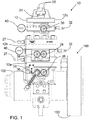
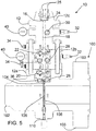
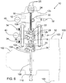
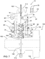
- An apparatus 10 for installing and removing a flow restrictor from a differential pressure measurement device 100 and a method of removing and installing a flow restrictor will now be described with reference to FIG. 1 through 7 .
- differential pressure measurement device 100 has a fitting 102 connected in line with a fluid line (not shown).
- Fitting 102 is shown as having a flange 103 at one end to be attached to a fluid line.
- the manner in which fitting 102 may be installed with a fluid line is well known in the art and will not be described further.
- Fitting 102 has a fitting opening 104 for receiving a flow restrictor 106 and a receptacle 108 for retaining flow restrictor 106.
- Fitting opening 104 is located in the sidewall of fitting 102, such that flow restrictor 106 is inserted through fitting opening 104 in a direction that is perpendicular to the direction of flow through fitting 102.
- flow restrictor 106 is an orifice plate that is rectangular and that has an aperture 112.
- the plate of flow restrictor 106 is oriented perpendicular to the direction of flow through fitting 102, such that the flow passes through aperture 112.
- Flow restrictor 106 is held by receptacle 108 such that aperture 112 is preferably centered within the inner bore of fitting 102 and may be adjusted by alignment pins 110 set in fitting 102 to ensure aperture 112 is properly positioned.
- Aperture 112 results in a pressure differential across flow restrictor 106, which may then be used to calculate the flow rate through the fluid line as is known in the art.
- the various designs and uses of differential pressure measurement devices 100 are known in the art and will not be discussed further. While the present description relates to a common design, it will be understood that modifications to what is shown and described may be used.
- apparatus 10 includes a seal housing 12 that extends away from fitting opening 104 of fitting 102.
- Seal housing 12 is sealed to fitting opening 104 of fitting 102 and has a housing opening 16 spaced from fitting opening 104 of fitting 102.
- a channel 18 connects fitting opening 104 to housing opening 16.
- channel 18 is a longitudinal channel that is sized to receive the width and thickness of the orifice plate, however it will be understood that channel 18 may be altered to accommodate different types of flow restrictors.
- seal housing 12 is actually made from three sections labelled 12a, 12b and 12c, where seal housing 12 is sealed to fitting opening 104 by integrally forming seal housing section 12a with fitting 102. Sections 12b and 12c are shows as being bolted together and onto section 12a. Alternatively, section 12a may be a separate piece and sealed to fitting opening 104 in another manner. Other modifications may be made by those skilled in the art.
- Seal housing 12 has a first seal 20 that seals fitting opening 104, a second seal 22 spaced from first seal 20 along channel 18, and a third seal 24 that seals housing opening 16.
- third seal 24 is a seal bar that is clamped by pin connectors 25 at housing opening 16 of seal housing 12. Third seal 24 can then be unclamped and removed from housing opening 16 to provide access to channel 18.
- the distance between first seal 20 and third seal 24 is greater than the height of flow restrictor 106, measured in the direction of channel 18, such that flow restrictor 106 may be isolated from atmosphere (or other external pressure if not working at atmospheric pressure) and from the pressure in fitting 102.
- the pressure within channel 18 to be equalized to either atmosphere or to the pressure in fitting 102, depending on whether flow restrictor 106 is being installed or removed.
- the distance between second seal 22 and third seal 24 is greater than the height of flow restrictor 106, which allows a double seal to be set prior to opening seal housing 12 to atmospheric pressure.
- each seal 20, 22 and 24 is selectively retractable between an extended, sealing position shown in FIG. 3 and retracted, open positions variously shown in FIG. 5-7 that unseals and unblock channel 18.
- seals 20, 22 and 24 permit flow restrictor 106 to move along channel 18 unhindered by the respective seals.
- first seal 20 and second seal 22 are retractable using rotating actuators 36 and 38, respectively.
- a releasable lock 39 may lock seal 20, 22 or 24 in the sealed position. Multiple locks may be provided to enable each of first seal 20, second seal 22 and third seal 24 to be locked individually.
- first seal 20 and second seal 22 may be sealed using a valve sealant grease compound injected by a grease gun 27 shown in FIG. 1 .
- Valve sealant grease compound is injected through by the grease gun 27 and injected between the surfaces of a valve seat and valve strip where seals 20 and 22 reside.
- the grease gun 27 may not be necessary where elastomer o-rings are embedded into the valve seat.
- first driver 26 positioned below first seal 20
- second driver 28 positioned between first and second seals 20 and 22
- third driver 30 positioned between second and third seals 22 and 24.
- Drivers 26, 28 and 30 engage flow restrictor 106 in turn to move flow restrictor 106 along channel 18 between receptacle 108 in fitting 102 and housing opening 16 of seal housing 12.
- each of first driver 26, second driver 28 and third driver 30 have a profile 29 that engages a corresponding profile 114 on flow restrictor 106.
- Channel 18 may be considered to be the space along which flow restrictor 106 passes, or in other words, the opening provided by seals in the open position and the plate carriers. While in some examples the physical dimensions of the channel may be larger at certain points above or below each respective seal or plate carrier, the channel itself may be considered the space required to move the flow restrictor. As can be seen, housing opening 16 is preferably directly in line with channel 18 and seal opening 104, such that flow restrictor 106 moves directly from an installed position to a removed position.
- bleeder valves 32 and equalizer valves 34 are preferably used to equalize the pressure as flow restrictor 106 passes through seal housing 12. As shown, there is a bleeder valve 32 in fluid communication with the compartment formed by first seal 20 and second seal 22, as well as a bleeder valve 32 in communication with the compartment formed by second seal 22 and third seal 24. Bleeder valves 32 allow the pressure in seal housing 12 held by the respective seals to be slowly released prior to opening third seal 24. As shown, equalizer valves 34 are provided in conjunction with first and second seals 20 and 22. These valves permit pressure to be equalized across each seal 20 and 22, such that when they are opened, the risk of damage due to a pressure differential or sudden pressure drop is reduced.
- equalizer valve 34 carried by first seal 20 may be opened to equalize the pressure between first and seconds seals 20 and 22 or first and third seals 20 and 24 with the pressure in fitting 102 prior to opening first seal 20.
- Pressure gauges 40 are preferably incorporated to measure the pressure in channel 18.
- a pressure gauge be positioned to measure the pressure in the compartment formed by first seal 20 and second seal 22 and a second pressure gauge 40 positioned to measure the pressure in the compartment formed by second seal 22 and third seal 24.
- the triple chamber orifice fitting provides the operator with a second layer of safety over the dual chamber orifice fitting during the inspection and/or removal of the orifice plate. While the operator has the top chamber open to atmosphere for access to the orifice plate, the pressure is being blocked by the lower inner valve. Should this lower valve leak, with the mid chamber bleeder valve open, the pressure can build up stopping the possibility of a leak into the upper chamber. As can be seen, when the seal bar 24 is removed to remove the flow restrictor 106, the first seal 20 and the second seal 22 are closed and the bleeder valve 32 in the compartment created between first seal 20 and second seal 22 is open to bleed off any leaking through bleeder valve 32.
- the bleeder valve 32 may be open to atmosphere or to a fluid reservoir with a lower pressure. Either of these may be considered an external pressure. This design protects the operator during orifice plate removal against coming into contact with any gas pressure release.
- apparatus 10 An example of the operation of apparatus 10 will now be described with reference to FIG. 1 through 7 .
- the steps outlined below are given as an example of a safe method, based on the design of the example shown in the drawings. It will be understood that the operation may be modified based on the preferences of the user and the particular design of apparatus 10.
- Apparatus 10 is in normal operation when, as shown in FIG. 1 and 2 , orifice plate is concentric in the flow line, both the lower and upper inner valves are closed, the two equalizer valves are closed, the bleeder valves are closed, the middle and upper chambers are depressurized and the lower chamber is pressurized. Flow of the gas or liquid passing through the orifice plate creates the differential pressure which is measured and used for the calculation of the flow rate through the pipe line.
- flow restrictor 106 is made up of an orifice plate carried by a plate carrier, which has a seal that engages receptacle 108.
Landscapes
- Physics & Mathematics (AREA)
- General Physics & Mathematics (AREA)
- Fluid Mechanics (AREA)
- Engineering & Computer Science (AREA)
- Mechanical Engineering (AREA)
- Measuring Fluid Pressure (AREA)
- Infusion, Injection, And Reservoir Apparatuses (AREA)
- Sliding Valves (AREA)
- Safety Valves (AREA)
- Flow Control (AREA)
Claims (23)
- Appareil (10) permettant de poser et de déposer un réducteur de débit (106) d'un dispositif de mesure de pression différentielle (100), le dispositif de mesure de pression différentielle (100) comprenant un raccord (102) connecté en ligne à une ligne de fluide, le raccord (102) présentant une ouverture de raccord (104) destinée à recevoir le réducteur de débit (106) et un réceptacle (108) destiné à retenir le réducteur de débit (106), l'appareil (10) comprenant:un boîtier étanche (12) s'étendant à distance de l'ouverture de raccord (104) du raccord (102), le boîtier étanche (12) étant étanche par rapport à l'ouverture de raccord (104) du raccord (102), le boîtier étanche (12) présentant une ouverture de boîtier (16) espacée de l'ouverture de raccord (104) du raccord (102), etun canal (18) connectant l'ouverture de boîtier (16) à l'ouverture de raccord (104),une série d'éléments d'entraînement rotatifs (26, 28, 30) qui sont espacés le long du canal (18), les éléments d'entraînement rotatifs (26, 28, 30) engageant le réducteur de débit (106) et déplaçant le réducteur de débit (106) le long du canal (18) entre le réceptacle (108) dans le raccord (102) et l'ouverture de boîtier (16) du boîtier étanche (12);caractérisé en ce que:un premier joint (20) obture l'ouverture de raccord (104), un deuxième joint (22) est espacé du premier joint (20) le long du canal (18), et un troisième joint (24) obture l'ouverture de boîtier (16), la distance entre le deuxième joint (22) et le troisième joint (24) étant plus grande que la hauteur du réducteur de débit (106) dans la direction du canal (18) qui obture l'ouverture de boîtier (16), chacun des premier (20), deuxième (22) et troisième (24) joints pouvant être rétracté de façon sélective entre une position étendue d'étanchéité, qui obture et bloque le canal (18) et une position rétractée ouverte, qui dégage et débloque le canal (18);un compartiment est formé entre le premier joint et le deuxième joint et un autre compartiment est formé entre le deuxième joint et le troisième joint; etune première soupape de purge (32) est positionnée entre le premier (20) et le deuxième (22) joints et une seconde soupape de purge (32) est positionnée entre le deuxième (22) et le troisième (24) joints, chacune des première et seconde soupapes de purge étant utilisée pour égaliser la pression entre le canal (18) et une pression extérieure afin d'éliminer le risque de fuite de pression vers le compartiment formé entre le deuxième joint et le troisième joint.
- Appareil (10) selon la revendication 1, dans lequel le réducteur de débit (106) est une plaque à orifices.
- Appareil (10) selon la revendication 2, dans lequel le canal (18) est un canal longitudinal qui est dimensionné de façon à recevoir la largeur et l'épaisseur de la plaque à orifices.
- Appareil (10) selon la revendication 1, dans lequel au moins le premier joint (20) et le deuxième joint (22) sont rétractés en utilisant un actionneur rotatif (36, 38).
- Appareil (10) selon la revendication 1, dans lequel au moins un du premier joint (20) et du deuxième joint (22) est verrouillé dans la position d'étanchéité par un verrou libérable (39).
- Appareil (10) selon la revendication 1, dans lequel chaque élément d'entraînement rotatif (26, 28, 30) comprend un profil qui engage un profil correspondant sur le réducteur de débit (106).
- Appareil (10) selon la revendication 1, dans lequel la série d'éléments d'entraînement rotatifs (26, 28, 30) comprend un premier élément d'entraînement rotatif (26) positionné entre le premier joint (20) et l'ouverture de raccord (104) du raccord (102), un deuxième élément d'entraînement rotatif (28) positionné entre le premier joint (20) et le deuxième joint (22), et un troisième élément d'entraînement (30) positionné entre le deuxième joint (22) et le troisième joint (24) .
- Appareil (10) selon la revendication 1, comprenant une première soupape d'égalisation (34) pour égaliser la pression à travers le premier joint (20) et une seconde soupape d'égalisation (34) pour égaliser la pression à travers le deuxième joint (22).
- Appareil (10) selon la revendication 1, comprenant en outre des capteurs de pression (40) entre le premier (20) et le deuxième (22) joints et entre le deuxième (22) et le troisième (24) joints pour mesurer la pression dans le canal (18).
- Appareil (10) selon la revendication 1, dans lequel le troisième joint (24) est une barre d'étanchéité attachée par des connecteurs à broches (25) à l'ouverture de boîtier (16) du boîtier étanche (12) .
- Appareil (10) selon la revendication 2, dans lequel la plaque à orifices est portée par un support de plaque.
- Procédé pour déposer un réducteur de débit (106) d'un dispositif de mesure de pression différentielle (100), en utilisant l'appareil de la revendication 1, le procédé comprenant les étapes suivantes:procurer un boîtier étanche (12) s'étendant à distance de l'ouverture de raccord (104) du raccord (102), le boîtier étanche (12) étant étanche par rapport à l'ouverture de raccord (104) du raccord (102), le boîtier étanche (12) présentant une ouverture de boîtier (16) espacée de l'ouverture de raccord (104) du raccord (102), et un canal (18) connectant l'ouverture de boîtier (16) à l'ouverture de raccord (104), le canal (18) comportant un premier joint (20), un deuxième joint (22) et un troisième joint (24) espacés le long du canal (18) dans une position d'étanchéité et une série d'éléments d'entraînement rotatifs (26, 28, 30) espacés le long du canal (18);déplacer le premier (20) et le deuxième (22) joints de la position d'étanchéité à une position rétractée ouverte;déplacer le réducteur de débit (106) du réceptacle (108) le long du canal (18) en direction du troisième joint (24);déplacer le premier (20) et le deuxième (22) joints vers la position d'étanchéité et ouvrir les soupapes de purge (32) entre le premier (20) et le deuxième (22) joints et entre le deuxième (22) et le troisième (24) joints pour égaliser la pression dans le canal (18) et à l'extérieur du canal (18); etouvrir le troisième joint (24) et déposer le réducteur de débit (106) hors du canal (18).
- Procédé selon la revendication 12, comprenant en outre l'étape de fermeture du premier (20) et du deuxième (22) joints après le déplacement du réducteur de débit (106) en direction du troisième joint (24).
- Procédé selon la revendication 12, dans lequel le réducteur de débit (106) est une plaque à orifices.
- Procédé selon la revendication 14, dans lequel le canal (18) est un canal longitudinal qui est dimensionné de façon à recevoir la largeur et l'épaisseur de la plaque à orifices.
- Procédé selon la revendication 12, dans lequel au moins un du premier joint (20) et du deuxième joint (22) est rétracté et étendu en utilisant un actionneur rotatif (36, 38).
- Procédé selon la revendication 12, comprenant en outre l'étape de libération d'un verrou libérable (39) sur au moins un du premier joint (20) et du deuxième joint (22) avant de rétracter le joint respectif de la position d'étanchéité.
- Procédé selon la revendication 12, dans lequel les éléments d'entraînement rotatifs (26, 28, 30) comprennent un profil qui engage un profil correspondant sur le réducteur de débit (106).
- Procédé selon la revendication 12, dans lequel la série d'éléments d'entraînement rotatifs (26, 28, 30) comprend un premier élément d'entraînement rotatif (26) positionné entre le premier joint (20) et l'ouverture de raccord (104) du raccord (102), un deuxième élément d'entraînement rotatif (28) positionné entre le premier joint (20) et le deuxième joint (22), et un troisième élément d'entraînement rotatif (30) positionné entre le deuxième joint (22) et le troisième joint (24).
- Procédé selon la revendication 12, comprenant en outre les étapes d'ouverture d'une première soupape d'égalisation (34) qui égalise la pression à travers le premier joint (20) et d'une seconde soupape d'égalisation (34) qui égalise la pression à travers le deuxième joint (22) avant l'ouverture du premier (20) et du deuxième (22) joints.
- Procédé selon la revendication 12, dans lequel l'ouverture du troisième joint (24) comprend la libération de connecteurs à broches (25) qui fixent une barre d'étanchéité à l'ouverture de boîtier (16) du boîtier étanche (12).
- Procédé selon la revendication 12, comprenant en outre la repose du réducteur de débit (106) en:déplaçant le premier (20) et le deuxième (22) joints vers la position d'étanchéité; enouvrant le troisième joint (24) et en insérant le réducteur de débit (106) dans le canal (18); endéplaçant le réducteur de débit (106) au bas du canal (18) au-delà du troisième joint (24) et en fermant le troisième joint (24); et enouvrant le premier (20) et le deuxième (22) joints et en déplaçant le réducteur de débit (106) dans le réceptacle (108) du raccord (102).
- Procédé selon la revendication 22, comprenant en outre l'étape d'ouverture d'une première soupape d'égalisation (34) qui égalise la pression à travers le premier joint (20) et d'une seconde soupape d'égalisation (34) qui égalise la pression à travers le deuxième joint (22) avant l'ouverture du premier (20) et du deuxième (22) joints avant l'ouverture du premier (20) et du deuxième (22) joints avant le déplacement du réducteur de débit (106) dans le réceptacle (108) du raccord (102).
Applications Claiming Priority (1)
| Application Number | Priority Date | Filing Date | Title |
|---|---|---|---|
| PCT/CA2013/050117 WO2014124514A1 (fr) | 2013-02-15 | 2013-02-15 | Procédé et appareil permettant de poser et de déposer un réducteur de débit d'un dispositif de mesure de pression différentielle |
Publications (3)
| Publication Number | Publication Date |
|---|---|
| EP2956747A1 EP2956747A1 (fr) | 2015-12-23 |
| EP2956747A4 EP2956747A4 (fr) | 2016-09-28 |
| EP2956747B1 true EP2956747B1 (fr) | 2018-03-21 |
Family
ID=51353441
Family Applications (1)
| Application Number | Title | Priority Date | Filing Date |
|---|---|---|---|
| EP13875119.3A Active EP2956747B1 (fr) | 2013-02-15 | 2013-02-15 | Procédé et appareil permettant de poser et de déposer un réducteur de débit d'un dispositif de mesure de pression différentielle |
Country Status (10)
| Country | Link |
|---|---|
| US (1) | US9527171B2 (fr) |
| EP (1) | EP2956747B1 (fr) |
| CN (1) | CN104995488B (fr) |
| BR (1) | BR112015019556B1 (fr) |
| CA (1) | CA2897226C (fr) |
| ES (1) | ES2674354T3 (fr) |
| MX (1) | MX360714B (fr) |
| MY (1) | MY183270A (fr) |
| SG (1) | SG11201505476SA (fr) |
| WO (1) | WO2014124514A1 (fr) |
Families Citing this family (6)
| Publication number | Priority date | Publication date | Assignee | Title |
|---|---|---|---|---|
| MY168309A (en) | 2011-03-09 | 2018-10-29 | Fund Leading Innova | Double isolation for double chamber differential pressure meter |
| RU2694168C2 (ru) * | 2014-12-12 | 2019-07-09 | ДЭНИЕЛ МЕЖЕМЕНТ энд КОНТРОЛ, ИНК. | Система многократного двойного блокирования и выпуска для крепления диафрагмы |
| US10317003B2 (en) * | 2015-07-22 | 2019-06-11 | Daniel Measurement And Control, Inc. | Double block and bleed system for an orifice fitting |
| CN108931272B (zh) * | 2017-05-27 | 2021-12-31 | 深圳市美好创亿医疗科技股份有限公司 | 多孔压差流量传感器及肺功能仪 |
| AU2020338966A1 (en) * | 2019-08-23 | 2022-03-31 | Fisher & Paykel Healthcare Limited | Liquid chamber for a breathing assistance apparatus |
| CN113340364B (zh) * | 2021-06-22 | 2021-12-07 | 武汉新烽光电股份有限公司 | 一种便于野外使用的投入式超声波流量监测仪 |
Citations (2)
| Publication number | Priority date | Publication date | Assignee | Title |
|---|---|---|---|---|
| US3860033A (en) * | 1973-04-13 | 1975-01-14 | M & J Valve Co | Flow diverting apparatus and method |
| DE2605039A1 (de) * | 1975-02-12 | 1976-08-26 | M & J Dev Co | Durchflussteuervorrichtung |
Family Cites Families (24)
| Publication number | Priority date | Publication date | Assignee | Title |
|---|---|---|---|---|
| US1938460A (en) | 1933-12-05 | Orifice fitting | ||
| US4014366A (en) * | 1974-03-18 | 1977-03-29 | Critendon Morris K | Orifice fitting conversion apparatus |
| US4193574A (en) | 1978-10-27 | 1980-03-18 | Barnes Johney H | Well shut off device |
| US4275763A (en) | 1979-05-25 | 1981-06-30 | Standard Oil Company (Indiana) | Double-slide valve |
| FR2470326B1 (fr) | 1979-11-19 | 1986-05-23 | Reglerbau Mannemann Gmbh Co Kg | Dispositif porte-orifice pour mesure de debit dans les canalisations sous pression |
| CH649359A5 (de) | 1980-11-26 | 1985-05-15 | Sulzer Ag | Plattenschieber. |
| US4425806A (en) | 1982-03-29 | 1984-01-17 | Grove Valve And Regulator Company | Modular orifice meter with isolation chamber valve closure |
| US4476730A (en) * | 1982-09-30 | 1984-10-16 | Grove Valve And Regulator Company | Orifice meter with pressure venting and equalizing safety device |
| US4785844A (en) | 1987-08-26 | 1988-11-22 | C & S Valve Company | Double-seal flexible gate valve |
| US5094272A (en) * | 1990-06-11 | 1992-03-10 | Foster James H | Adjustable orifice plate seal |
| US5094270A (en) | 1991-03-14 | 1992-03-10 | Dril-Quip Inc. | Double gated valve |
| US5305796A (en) * | 1992-08-05 | 1994-04-26 | G-H Flow Automation, Inc. | Apparatus and method for centering an orifice plate |
| US5778933A (en) | 1995-03-15 | 1998-07-14 | Crane Manufacturing, Inc. | Orifice fitting |
| US5474103A (en) | 1995-03-22 | 1995-12-12 | Klak; Steven P. | Safety guard for orifice fitting device |
| US5836356A (en) | 1996-03-12 | 1998-11-17 | Mueller Steam Specialty, A Divison Of Core Industries, Inc. | Dual chamber orifice fitting |
| GB2319088A (en) * | 1996-03-12 | 1998-05-13 | Mueller Steam Specialty | A dual chamber orifice fitting |
| DE19802986A1 (de) | 1998-01-28 | 1999-07-29 | Colortronic Gmbh | Absperrorgan |
| GB9805120D0 (en) | 1998-03-11 | 1998-05-06 | British Gas Plc | Sliding plate valve |
| CN2380765Y (zh) | 1999-06-08 | 2000-05-31 | 池凤彩 | 一种双向止回硬密封旋启式止回阀 |
| GB0024507D0 (en) | 2000-10-06 | 2000-11-22 | Oliver Twinsafe Valves Ltd | An isolation valve assembly |
| US7118114B2 (en) * | 2003-05-15 | 2006-10-10 | Woodward Governor Company | Dynamic sealing arrangement for movable shaft |
| US7063107B2 (en) | 2004-05-19 | 2006-06-20 | Daniel Industries, Inc. | Dual chamber orifice fitting body |
| US7870873B2 (en) | 2006-02-13 | 2011-01-18 | Daniel Industries, Inc. | Dual chamber orifice fitting isolation valve |
| MY168309A (en) | 2011-03-09 | 2018-10-29 | Fund Leading Innova | Double isolation for double chamber differential pressure meter |
-
2013
- 2013-02-15 WO PCT/CA2013/050117 patent/WO2014124514A1/fr not_active Ceased
- 2013-02-15 US US14/760,495 patent/US9527171B2/en active Active
- 2013-02-15 ES ES13875119.3T patent/ES2674354T3/es active Active
- 2013-02-15 SG SG11201505476SA patent/SG11201505476SA/en unknown
- 2013-02-15 EP EP13875119.3A patent/EP2956747B1/fr active Active
- 2013-02-15 BR BR112015019556-3A patent/BR112015019556B1/pt active IP Right Grant
- 2013-02-15 CA CA2897226A patent/CA2897226C/fr active Active
- 2013-02-15 MY MYPI2015702623A patent/MY183270A/en unknown
- 2013-02-15 CN CN201380072995.6A patent/CN104995488B/zh active Active
- 2013-02-15 MX MX2015010533A patent/MX360714B/es active IP Right Grant
Patent Citations (2)
| Publication number | Priority date | Publication date | Assignee | Title |
|---|---|---|---|---|
| US3860033A (en) * | 1973-04-13 | 1975-01-14 | M & J Valve Co | Flow diverting apparatus and method |
| DE2605039A1 (de) * | 1975-02-12 | 1976-08-26 | M & J Dev Co | Durchflussteuervorrichtung |
Also Published As
| Publication number | Publication date |
|---|---|
| CA2897226A1 (fr) | 2014-08-21 |
| US9527171B2 (en) | 2016-12-27 |
| CA2897226C (fr) | 2017-09-26 |
| BR112015019556A2 (pt) | 2017-07-18 |
| BR112015019556B1 (pt) | 2020-11-10 |
| MX360714B (es) | 2018-11-14 |
| ES2674354T3 (es) | 2018-06-29 |
| CN104995488A (zh) | 2015-10-21 |
| MX2015010533A (es) | 2015-11-16 |
| SG11201505476SA (en) | 2015-08-28 |
| US20150352674A1 (en) | 2015-12-10 |
| EP2956747A4 (fr) | 2016-09-28 |
| WO2014124514A1 (fr) | 2014-08-21 |
| MY183270A (en) | 2021-02-18 |
| EP2956747A1 (fr) | 2015-12-23 |
| CN104995488B (zh) | 2018-12-07 |
Similar Documents
| Publication | Publication Date | Title |
|---|---|---|
| EP2956747B1 (fr) | Procédé et appareil permettant de poser et de déposer un réducteur de débit d'un dispositif de mesure de pression différentielle | |
| EP2334964B1 (fr) | Éléments de commande de débit destinés à être utilisés avec des soupapes | |
| JP5953350B2 (ja) | 取り外し可能な内部作動機構を有するバルブ | |
| EP3230695B1 (fr) | Système à multiples doubles fermetures et purges pour un raccord d'orifice | |
| EP3221622B1 (fr) | Clapet de retenue à piston sans claquement pouvant être isolé | |
| JP5889962B2 (ja) | バルブと共に用いられる流体流れ制御部材 | |
| AU2009302720A1 (en) | Apparatus to determine a position of a valve | |
| US8459305B2 (en) | Dual chamber orifice fitting | |
| US5474103A (en) | Safety guard for orifice fitting device | |
| EP2334966B1 (fr) | Éléments de commande de débit destinés à être utilisés avec des soupapes | |
| CA2993298C (fr) | Systeme a double fonction d'arret et de purge pour un accessoire de diaphragme | |
| US20130068306A1 (en) | Drain valve and method for operating a drain valve | |
| EP2242942B1 (fr) | Plaque porte-soupape à encombrement réduit | |
| US20110240156A1 (en) | Double Block and Bleed Sandwich-Type Valve | |
| CA2988243C (fr) | Valve de type obturateur amovible | |
| US20150276115A1 (en) | Method of installing an emergency flow restrictor device (efrd) on a pipeline |
Legal Events
| Date | Code | Title | Description |
|---|---|---|---|
| PUAI | Public reference made under article 153(3) epc to a published international application that has entered the european phase |
Free format text: ORIGINAL CODE: 0009012 |
|
| 17P | Request for examination filed |
Effective date: 20150713 |
|
| AK | Designated contracting states |
Kind code of ref document: A1 Designated state(s): AL AT BE BG CH CY CZ DE DK EE ES FI FR GB GR HR HU IE IS IT LI LT LU LV MC MK MT NL NO PL PT RO RS SE SI SK SM TR |
|
| AX | Request for extension of the european patent |
Extension state: BA ME |
|
| DAX | Request for extension of the european patent (deleted) | ||
| A4 | Supplementary search report drawn up and despatched |
Effective date: 20160830 |
|
| RIC1 | Information provided on ipc code assigned before grant |
Ipc: G01F 1/42 20060101ALI20160824BHEP Ipc: B23P 17/04 20060101ALI20160824BHEP Ipc: G01L 13/00 20060101AFI20160824BHEP |
|
| REG | Reference to a national code |
Ref country code: DE Ref legal event code: R079 Ref document number: 602013034912 Country of ref document: DE Free format text: PREVIOUS MAIN CLASS: G01F0001400000 Ipc: G01L0013000000 |
|
| GRAP | Despatch of communication of intention to grant a patent |
Free format text: ORIGINAL CODE: EPIDOSNIGR1 |
|
| STAA | Information on the status of an ep patent application or granted ep patent |
Free format text: STATUS: GRANT OF PATENT IS INTENDED |
|
| RIC1 | Information provided on ipc code assigned before grant |
Ipc: G01F 1/42 20060101ALI20170824BHEP Ipc: G01L 13/00 20060101AFI20170824BHEP Ipc: B23P 17/04 20060101ALI20170824BHEP Ipc: G01F 15/00 20060101ALI20170824BHEP Ipc: G01F 15/14 20060101ALN20170824BHEP Ipc: G01F 15/18 20060101ALN20170824BHEP |
|
| INTG | Intention to grant announced |
Effective date: 20170919 |
|
| GRAS | Grant fee paid |
Free format text: ORIGINAL CODE: EPIDOSNIGR3 |
|
| GRAA | (expected) grant |
Free format text: ORIGINAL CODE: 0009210 |
|
| STAA | Information on the status of an ep patent application or granted ep patent |
Free format text: STATUS: THE PATENT HAS BEEN GRANTED |
|
| AK | Designated contracting states |
Kind code of ref document: B1 Designated state(s): AL AT BE BG CH CY CZ DE DK EE ES FI FR GB GR HR HU IE IS IT LI LT LU LV MC MK MT NL NO PL PT RO RS SE SI SK SM TR |
|
| REG | Reference to a national code |
Ref country code: GB Ref legal event code: FG4D |
|
| REG | Reference to a national code |
Ref country code: CH Ref legal event code: EP |
|
| REG | Reference to a national code |
Ref country code: AT Ref legal event code: REF Ref document number: 981625 Country of ref document: AT Kind code of ref document: T Effective date: 20180415 |
|
| REG | Reference to a national code |
Ref country code: IE Ref legal event code: FG4D |
|
| REG | Reference to a national code |
Ref country code: DE Ref legal event code: R096 Ref document number: 602013034912 Country of ref document: DE |
|
| REG | Reference to a national code |
Ref country code: ES Ref legal event code: FG2A Ref document number: 2674354 Country of ref document: ES Kind code of ref document: T3 Effective date: 20180629 |
|
| REG | Reference to a national code |
Ref country code: NL Ref legal event code: MP Effective date: 20180321 |
|
| PG25 | Lapsed in a contracting state [announced via postgrant information from national office to epo] |
Ref country code: HR Free format text: LAPSE BECAUSE OF FAILURE TO SUBMIT A TRANSLATION OF THE DESCRIPTION OR TO PAY THE FEE WITHIN THE PRESCRIBED TIME-LIMIT Effective date: 20180321 Ref country code: LT Free format text: LAPSE BECAUSE OF FAILURE TO SUBMIT A TRANSLATION OF THE DESCRIPTION OR TO PAY THE FEE WITHIN THE PRESCRIBED TIME-LIMIT Effective date: 20180321 Ref country code: CY Free format text: LAPSE BECAUSE OF FAILURE TO SUBMIT A TRANSLATION OF THE DESCRIPTION OR TO PAY THE FEE WITHIN THE PRESCRIBED TIME-LIMIT Effective date: 20180321 Ref country code: FI Free format text: LAPSE BECAUSE OF FAILURE TO SUBMIT A TRANSLATION OF THE DESCRIPTION OR TO PAY THE FEE WITHIN THE PRESCRIBED TIME-LIMIT Effective date: 20180321 |
|
| REG | Reference to a national code |
Ref country code: LT Ref legal event code: MG4D |
|
| REG | Reference to a national code |
Ref country code: AT Ref legal event code: MK05 Ref document number: 981625 Country of ref document: AT Kind code of ref document: T Effective date: 20180321 |
|
| REG | Reference to a national code |
Ref country code: NO Ref legal event code: T2 Effective date: 20180321 |
|
| PG25 | Lapsed in a contracting state [announced via postgrant information from national office to epo] |
Ref country code: SE Free format text: LAPSE BECAUSE OF FAILURE TO SUBMIT A TRANSLATION OF THE DESCRIPTION OR TO PAY THE FEE WITHIN THE PRESCRIBED TIME-LIMIT Effective date: 20180321 Ref country code: RS Free format text: LAPSE BECAUSE OF FAILURE TO SUBMIT A TRANSLATION OF THE DESCRIPTION OR TO PAY THE FEE WITHIN THE PRESCRIBED TIME-LIMIT Effective date: 20180321 Ref country code: LV Free format text: LAPSE BECAUSE OF FAILURE TO SUBMIT A TRANSLATION OF THE DESCRIPTION OR TO PAY THE FEE WITHIN THE PRESCRIBED TIME-LIMIT Effective date: 20180321 Ref country code: BG Free format text: LAPSE BECAUSE OF FAILURE TO SUBMIT A TRANSLATION OF THE DESCRIPTION OR TO PAY THE FEE WITHIN THE PRESCRIBED TIME-LIMIT Effective date: 20180621 Ref country code: GR Free format text: LAPSE BECAUSE OF FAILURE TO SUBMIT A TRANSLATION OF THE DESCRIPTION OR TO PAY THE FEE WITHIN THE PRESCRIBED TIME-LIMIT Effective date: 20180622 |
|
| PG25 | Lapsed in a contracting state [announced via postgrant information from national office to epo] |
Ref country code: AL Free format text: LAPSE BECAUSE OF FAILURE TO SUBMIT A TRANSLATION OF THE DESCRIPTION OR TO PAY THE FEE WITHIN THE PRESCRIBED TIME-LIMIT Effective date: 20180321 Ref country code: PL Free format text: LAPSE BECAUSE OF FAILURE TO SUBMIT A TRANSLATION OF THE DESCRIPTION OR TO PAY THE FEE WITHIN THE PRESCRIBED TIME-LIMIT Effective date: 20180321 Ref country code: NL Free format text: LAPSE BECAUSE OF FAILURE TO SUBMIT A TRANSLATION OF THE DESCRIPTION OR TO PAY THE FEE WITHIN THE PRESCRIBED TIME-LIMIT Effective date: 20180321 Ref country code: RO Free format text: LAPSE BECAUSE OF FAILURE TO SUBMIT A TRANSLATION OF THE DESCRIPTION OR TO PAY THE FEE WITHIN THE PRESCRIBED TIME-LIMIT Effective date: 20180321 Ref country code: EE Free format text: LAPSE BECAUSE OF FAILURE TO SUBMIT A TRANSLATION OF THE DESCRIPTION OR TO PAY THE FEE WITHIN THE PRESCRIBED TIME-LIMIT Effective date: 20180321 |
|
| PG25 | Lapsed in a contracting state [announced via postgrant information from national office to epo] |
Ref country code: SK Free format text: LAPSE BECAUSE OF FAILURE TO SUBMIT A TRANSLATION OF THE DESCRIPTION OR TO PAY THE FEE WITHIN THE PRESCRIBED TIME-LIMIT Effective date: 20180321 Ref country code: CZ Free format text: LAPSE BECAUSE OF FAILURE TO SUBMIT A TRANSLATION OF THE DESCRIPTION OR TO PAY THE FEE WITHIN THE PRESCRIBED TIME-LIMIT Effective date: 20180321 Ref country code: SM Free format text: LAPSE BECAUSE OF FAILURE TO SUBMIT A TRANSLATION OF THE DESCRIPTION OR TO PAY THE FEE WITHIN THE PRESCRIBED TIME-LIMIT Effective date: 20180321 Ref country code: AT Free format text: LAPSE BECAUSE OF FAILURE TO SUBMIT A TRANSLATION OF THE DESCRIPTION OR TO PAY THE FEE WITHIN THE PRESCRIBED TIME-LIMIT Effective date: 20180321 |
|
| PG25 | Lapsed in a contracting state [announced via postgrant information from national office to epo] |
Ref country code: PT Free format text: LAPSE BECAUSE OF FAILURE TO SUBMIT A TRANSLATION OF THE DESCRIPTION OR TO PAY THE FEE WITHIN THE PRESCRIBED TIME-LIMIT Effective date: 20180723 |
|
| REG | Reference to a national code |
Ref country code: DE Ref legal event code: R097 Ref document number: 602013034912 Country of ref document: DE |
|
| PLBE | No opposition filed within time limit |
Free format text: ORIGINAL CODE: 0009261 |
|
| STAA | Information on the status of an ep patent application or granted ep patent |
Free format text: STATUS: NO OPPOSITION FILED WITHIN TIME LIMIT |
|
| PG25 | Lapsed in a contracting state [announced via postgrant information from national office to epo] |
Ref country code: DK Free format text: LAPSE BECAUSE OF FAILURE TO SUBMIT A TRANSLATION OF THE DESCRIPTION OR TO PAY THE FEE WITHIN THE PRESCRIBED TIME-LIMIT Effective date: 20180321 |
|
| 26N | No opposition filed |
Effective date: 20190102 |
|
| PG25 | Lapsed in a contracting state [announced via postgrant information from national office to epo] |
Ref country code: SI Free format text: LAPSE BECAUSE OF FAILURE TO SUBMIT A TRANSLATION OF THE DESCRIPTION OR TO PAY THE FEE WITHIN THE PRESCRIBED TIME-LIMIT Effective date: 20180321 |
|
| REG | Reference to a national code |
Ref country code: CH Ref legal event code: PL |
|
| PG25 | Lapsed in a contracting state [announced via postgrant information from national office to epo] |
Ref country code: LU Free format text: LAPSE BECAUSE OF NON-PAYMENT OF DUE FEES Effective date: 20190215 Ref country code: MC Free format text: LAPSE BECAUSE OF FAILURE TO SUBMIT A TRANSLATION OF THE DESCRIPTION OR TO PAY THE FEE WITHIN THE PRESCRIBED TIME-LIMIT Effective date: 20180321 |
|
| REG | Reference to a national code |
Ref country code: BE Ref legal event code: MM Effective date: 20190228 |
|
| REG | Reference to a national code |
Ref country code: IE Ref legal event code: MM4A |
|
| PG25 | Lapsed in a contracting state [announced via postgrant information from national office to epo] |
Ref country code: LI Free format text: LAPSE BECAUSE OF NON-PAYMENT OF DUE FEES Effective date: 20190228 Ref country code: CH Free format text: LAPSE BECAUSE OF NON-PAYMENT OF DUE FEES Effective date: 20190228 |
|
| PG25 | Lapsed in a contracting state [announced via postgrant information from national office to epo] |
Ref country code: IE Free format text: LAPSE BECAUSE OF NON-PAYMENT OF DUE FEES Effective date: 20190215 |
|
| PG25 | Lapsed in a contracting state [announced via postgrant information from national office to epo] |
Ref country code: BE Free format text: LAPSE BECAUSE OF NON-PAYMENT OF DUE FEES Effective date: 20190228 Ref country code: FR Free format text: LAPSE BECAUSE OF NON-PAYMENT OF DUE FEES Effective date: 20190228 |
|
| PG25 | Lapsed in a contracting state [announced via postgrant information from national office to epo] |
Ref country code: TR Free format text: LAPSE BECAUSE OF FAILURE TO SUBMIT A TRANSLATION OF THE DESCRIPTION OR TO PAY THE FEE WITHIN THE PRESCRIBED TIME-LIMIT Effective date: 20180321 |
|
| PG25 | Lapsed in a contracting state [announced via postgrant information from national office to epo] |
Ref country code: MT Free format text: LAPSE BECAUSE OF NON-PAYMENT OF DUE FEES Effective date: 20190215 |
|
| PG25 | Lapsed in a contracting state [announced via postgrant information from national office to epo] |
Ref country code: IS Free format text: LAPSE BECAUSE OF FAILURE TO SUBMIT A TRANSLATION OF THE DESCRIPTION OR TO PAY THE FEE WITHIN THE PRESCRIBED TIME-LIMIT Effective date: 20180721 |
|
| PG25 | Lapsed in a contracting state [announced via postgrant information from national office to epo] |
Ref country code: HU Free format text: LAPSE BECAUSE OF FAILURE TO SUBMIT A TRANSLATION OF THE DESCRIPTION OR TO PAY THE FEE WITHIN THE PRESCRIBED TIME-LIMIT; INVALID AB INITIO Effective date: 20130215 |
|
| PG25 | Lapsed in a contracting state [announced via postgrant information from national office to epo] |
Ref country code: MK Free format text: LAPSE BECAUSE OF FAILURE TO SUBMIT A TRANSLATION OF THE DESCRIPTION OR TO PAY THE FEE WITHIN THE PRESCRIBED TIME-LIMIT Effective date: 20180321 |
|
| PGFP | Annual fee paid to national office [announced via postgrant information from national office to epo] |
Ref country code: ES Payment date: 20250331 Year of fee payment: 13 |
|
| PGFP | Annual fee paid to national office [announced via postgrant information from national office to epo] |
Ref country code: GB Payment date: 20260115 Year of fee payment: 14 |
|
| PGFP | Annual fee paid to national office [announced via postgrant information from national office to epo] |
Ref country code: NO Payment date: 20260220 Year of fee payment: 14 Ref country code: DE Payment date: 20260218 Year of fee payment: 14 |
|
| PGFP | Annual fee paid to national office [announced via postgrant information from national office to epo] |
Ref country code: IT Payment date: 20260219 Year of fee payment: 14 |