EP2956780B1 - Bloc de bornes de connexion de compteur électrique et compteur électrique correspondant - Google Patents
Bloc de bornes de connexion de compteur électrique et compteur électrique correspondant Download PDFInfo
- Publication number
- EP2956780B1 EP2956780B1 EP14704582.7A EP14704582A EP2956780B1 EP 2956780 B1 EP2956780 B1 EP 2956780B1 EP 14704582 A EP14704582 A EP 14704582A EP 2956780 B1 EP2956780 B1 EP 2956780B1
- Authority
- EP
- European Patent Office
- Prior art keywords
- electricity meter
- contact
- terminal block
- connection terminal
- contacts
- Prior art date
- Legal status (The legal status is an assumption and is not a legal conclusion. Google has not performed a legal analysis and makes no representation as to the accuracy of the status listed.)
- Active
Links
Images










Classifications
-
- G—PHYSICS
- G01—MEASURING; TESTING
- G01R—MEASURING ELECTRIC VARIABLES; MEASURING MAGNETIC VARIABLES
- G01R11/00—Electromechanical arrangements for measuring time integral of electric power or current, e.g. of consumption
- G01R11/02—Constructional details
- G01R11/04—Housings; Supporting racks; Arrangements of terminals
-
- H—ELECTRICITY
- H01—ELECTRIC ELEMENTS
- H01R—ELECTRICALLY-CONDUCTIVE CONNECTIONS; STRUCTURAL ASSOCIATIONS OF A PLURALITY OF MUTUALLY-INSULATED ELECTRICAL CONNECTING ELEMENTS; COUPLING DEVICES; CURRENT COLLECTORS
- H01R13/00—Details of coupling devices of the kinds covered by groups H01R12/70 or H01R24/00 - H01R33/00
- H01R13/02—Contact members
- H01R13/03—Contact members characterised by the material, e.g. plating, or coating materials
-
- H—ELECTRICITY
- H01—ELECTRIC ELEMENTS
- H01R—ELECTRICALLY-CONDUCTIVE CONNECTIONS; STRUCTURAL ASSOCIATIONS OF A PLURALITY OF MUTUALLY-INSULATED ELECTRICAL CONNECTING ELEMENTS; COUPLING DEVICES; CURRENT COLLECTORS
- H01R13/00—Details of coupling devices of the kinds covered by groups H01R12/70 or H01R24/00 - H01R33/00
- H01R13/02—Contact members
- H01R13/10—Sockets for co-operation with pins or blades
- H01R13/11—Resilient sockets
- H01R13/112—Resilient sockets forked sockets having two legs
-
- H—ELECTRICITY
- H01—ELECTRIC ELEMENTS
- H01R—ELECTRICALLY-CONDUCTIVE CONNECTIONS; STRUCTURAL ASSOCIATIONS OF A PLURALITY OF MUTUALLY-INSULATED ELECTRICAL CONNECTING ELEMENTS; COUPLING DEVICES; CURRENT COLLECTORS
- H01R9/00—Structural associations of a plurality of mutually-insulated electrical connecting elements, e.g. terminal strips or terminal blocks; Terminals or binding posts mounted upon a base or in a case; Bases therefor
- H01R9/22—Bases, e.g. strip, block, panel
- H01R9/24—Terminal blocks
Definitions
- the invention relates to an electricity meter terminal block with an insulating material housing, with conductor terminals for connecting electrical power supply lines and with electricity meter terminals - for the electrically conductive connection of conductor terminals with associated terminal contacts of an electricity meter received by the electricity meter terminal block electricity meter.
- Electricity meters are used especially in households to measure the consumed electrical energy.
- the supply lines are looped through a power meter and measured the electrical energy consumed.
- the power supply lines i. H. the phase lines L1, L2, L3 and the neutral conductor N (return conductor) and possibly a protective earth PE are connected to conductor terminals of the electricity meter.
- the exchange of energy meters is very cumbersome and may only be carried out by skilled workers.
- the terminal blocks have an insulating housing with mounting elements for wall mounting, conductor terminals for connecting electrical power supply lines and electricity meter terminals for receiving and contacting associated terminals of an electricity meter.
- the terminals of the electricity meter are designed as pin contacts that dip into spring clip contacts.
- the spring clip contacts have two mutually opposite spring clip and an intermediate, the spring clip against each other pressing compression spring.
- DE 10 201 1 015 697 A1 discloses a counter switching block having at least two counter switch contacts per phase for connection to the electricity meter, which has at least two contact pieces per phase.
- the counter switching block comprises a switching element with which the counter switching contacts between an operating position and a removal position can be switched back and forth. Furthermore, a bridging device is provided for such a counter switching contact.
- the electricity meter terminals of the meter switch block are formed of two opposing, spring-loaded meter switch contacts. Upon insertion of the lock-up device, the electricity meter terminals are opened to facilitate removal or connection of an electricity meter while sparing the electricity meter terminals.
- DE 196 21 861 A1 shows a connector for plugging and connecting an electricity meter.
- the electricity meter has screw socket contacts for receiving pins that protrude from the connector and are also connected in the connector with screw socket contacts.
- terminal Blocks PTR Catalog 14 February 2013, pages 1 to 232, XP055118578 terminal blocks are described with tab terminal, which are provided and suitable for receiving a plug with an adjoining line. This can be snapped onto a rail terminal blocks are not set up for receiving a plug-on device.
- the electrical contact between the electricity meter terminal block and the electricity meter is performed by means of corresponding blade fork contacts.
- the fork contacts have the advantage of a direct and short current path from the terminal contact for the blade contact to the conductor terminal, which can also be realized using the material of the fork contact as a busbar preferably as a spring terminal connection.
- connection contact receiving openings for receiving in each case an associated terminal contact of an electricity meter are introduced into the insulating housing. These terminal contact receiving openings define an insertion direction of the terminal contacts in the insulating housing of the electricity meter terminal block.
- the energy meter terminals designed as fork contacts extend transversely to the insertion direction of associated blade contacts, which can be inserted into a respective terminal contact receiving opening.
- transverse is meant that the blade contacts through one of the fork contacts spanned level inserted into the contact slot formed by the fork contacts between the fork contacts and then contacted by these on both sides. It is therefore not important that the fork contacts are aligned exactly perpendicular to the insertion direction of the terminals.
- the extension direction of the fork contacts to the insertion direction should preferably be about 60 ° to 120 °. Under certain circumstances, but also more inclined variants are useful, which then still take advantage of transverse fork contacts.
- the conductor connections are preferably designed as spring-force clamping connections.
- the busbar piece of the spring terminal connections carries, for example, a clamping spring or cooperates with a U-shaped, directly pluggable clamping spring. From the free end of the busbar preferably fork contacts are then formed.
- the busbar in the region of the fork contact is bent away from a busbar plane opposite to the extension direction of the free ends of the fork tines and transitions over a deflection section into the section of the fork tines forming a receiving slot for a blade contact.
- the fork contact is bent in a U-shaped cross section and forms a relation to the busbar plane downwardly offset receiving space for an assigned blade contact. Due to the deflection portion and the bent away from the busbar plane portion of the fork contact is extended without increasing the size and it is achieved that the force applied by the fork contact clamping force and elasticity is significantly improved. In this case, the space occupied by the blade contact in the event of a clamped blade contact is used to lengthen the fork contacts.
- a contact slit which is narrower in comparison to the contact slit, adjoins a contact slit formed by the spaced-apart forks, which is provided for receiving a knife contact.
- At least one locking element is provided for locking the electricity meter terminal block with an inserted terminal contact of an electricity meter.
- locking is achieved on a very stable and solid material, namely the terminal contacts. It is thus proposed to use the usually formed of stable metal material terminal contacts for locking the electricity meter to the electricity meter terminal block with.
- the locking of an electricity meter to an electricity meter terminal block is important and critical in that misuse of electricity meters is safely avoided got to.
- an electricity meter terminal block with an insulating housing with conductor terminals for connecting electrical power supply lines and electricity meter terminals for electrically conductive connection of conductor terminals with associated terminal contacts of an electricity meter received from the electricity meter terminal block at least one locking element adjacent to an associated Electricity meter terminal has in the insulating housing.
- the locking element is spring-loaded and displaceable from an open position under spring force into a locking position. In the locking position, the locking element dips into a detent recess of an inserted connection contact of an energy meter.
- the spring-loaded locking element can be moved from the locking position to an open position in which the detent recess of an inserted terminal contact is released. This releases a locking of the connection contact on the latching recess and the energy meter can be easily removed.
- the insulating housing has open to the free ends of the forks of the fork contacts towards Brückerö réelleen for receiving Brücker-blade contacts of a recordable from the electricity meter terminal block bridging element.
- a bridging element With the help of such a bridging element, the replacement of an energy meter, the further operation of the downstream power supply system can be ensured.
- the electricity meter can thus with the help of a bridging element without affecting z. B. the supplied household.
- This locking element is then preferably designed as a spring-loaded latch for immersion in a detent recess of an inserted terminal contact of an electricity meter.
- the bridging element widens when plugged in the contact slot of the fork contact and thus allows a force-reduced or powerless insertion or removal of a blade contact from the associated contact slot.
- FIG. 1 shows a perspective view of an electricity meter terminal block 1 with attached thereto electricity meter 2 recognize.
- Protruding from the housing 3 of the electricity meter 2 on both sides of spaced guide tabs 4, which rest against side walls 5 of the electricity meter terminal block 1 and projections 6 and a bottom plate 7 of the electricity meter terminal block 1 a predetermined insertion and location of the electricity meter 2 to the electricity meter terminal block 1 to make sure.
- invisible blade contacts of the electricity meter 2 engage in invisible fork contacts of the electricity meter connection terminal block 1.
- the electricity meter terminal block 1 has, opposite to the electricity meter 2, conductor insertion openings 8 leading to invisible conductor terminals for connection of electric power supply lines inserted into the conductor insertion openings 8.
- the conductor connections are designed as spring terminal contacts, which form a terminal point for a respectively to be connected power supply line.
- the clamping points can be opened and closed by means of the operating levers 10, which are accessible from the upper side and are pivotably mounted in the insulating housing 9 of the electricity meter connection terminal block 1.
- bridge openings 11 are provided at the top of the insulating housing 9 of the electricity meter terminal block 1 adjacent to the power meter 2 on the same side of the operating levers 10. These bridge openings 11 serve to receive bridging contacts of a bridging element (not shown). This is a bridging during the replacement of an electricity meter 2 the conductor connections for the power supply lines possible so that the further supply of electrical energy is possible even when the electricity meter 2 is removed.
- the bridge openings 11 and the entire connection area are covered with a suitable cover.
- the cover (not visible) is preferably sealed in order to prevent improper bridging of a built-in energy meter 2 and thus a power theft.
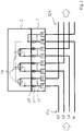
- FIG. 2 shows an electrical block diagram of the electricity meter terminal block 1 with the electricity meter 2 plugged in. It is clear that the power supply lines 12 with the three phases L1, L2, L3 and the return conductor N are guided to the conductor terminals 13a, 13c, 13e, 13g.
- the z. B. for supplying a building in this leading electrical power supply lines 12b are connected to the lead terminals 13b, 13d, 13f and 13h clamped.
- the lead terminals 13 a to 13 h are respectively led to electricity meter terminals 21.
- These electricity meter connection terminals 21 are provided for the electrically conductive plug connection of an electricity meter 2 with the electricity meter connection terminal block 1.
- the electricity meter 2 has a digital or analog measuring device 16 for measuring and recording the consumption of electrical energy at the three phases L1, L2 and L3 with respect to the return conductor N.
- the through the power supply lines 12a of the utility in the power supply line 12b of the consumer in the three-phase current flowing L1, L2 and L3 is thus summed relative to the voltage, thereby detecting the consumed electrical energy.
- conductor connections 13a to 13h can be bridged for connection of electrical power supply lines 12a, 12b by means of jumpers 17 illustrated in dashed lines. This ensures the further energy supply during the replacement of an energy meter 2.
- FIG. 3 shows a side sectional view of the electricity meter terminal block 1 with attached electricity meter 2. It is clear that the conductor insertion openings 8 for the introduction of electrical power supply lines 12a, 12b lead to an associated conductor connection 18 in the form of a spring-force terminal connection.
- This is z. B. from a loop-shaped curved clamping spring 19 (eg., Käfigzugfeder) and a power shank 20 is formed to clamp with the clamping leg under the spring force of the clamping spring 19, an electrical conductor between a transverse web at the free end of the clamping leg and the busbar piece 20.
- an operating lever 10 is pivotally received in the insulating housing 9 of the electricity meter terminal block 1.
- the bus bar 20 extends in the direction of the plugged electricity meter 2, wherein at the free end of the busbar 20 electricity meter connection terminals 21 are formed.
- the busbar 20 is folded over to the bottom plate 7 of the insulating housing 9 out and folded after a deflection section 22 in the bottom plate 7 opposite direction.
- Two forks 23 extend parallel to each other and are spaced from each other by a contact slot for receiving a blade contact 24 of the electricity meter 2. It can be seen that the forks 23 are transverse to the direction of insertion of an associated blade contact 24. there it does not depend on the exact right-angled arrangement to each other. It is essential that when inserting the blade contact 24 in the insertion direction E of the blade contact 24 is not inserted from the free end of the forks 23 in the contact slot, but over a plane spanned by the forks 23 level.
- the blade contact 24 is received by the U-shaped bend of the fork contact 21 in a space spanned by the fork contact 21, wherein the length of the electricity meter terminal block 1 is not increased in the extension direction despite large extension length of the fork contacts 21.
- the electricity meter terminal block 1 can thus be made very compact by this space-saving arrangement of the fork contacts 21.
- a locking element 28 is received in the insulating housing 9 in the electricity meter terminal block 1 in front of the forks 23.
- This locking element 28 is spring-loaded by a compression spring 29 to immerse in the detent position shown in a detent recess 30 of the associated blade contact 24.
- the electricity meter 2 is latched via the latching recesses 30 of the associated blade contact 24 with the aid of the locking element 28 on the insulating housing 9 of the electricity meter connection terminal block 1.
- This type of construction of the locking element 28 and the latch is very space-saving and uses the massive material of the blade contacts 24 for locking. For unlocking the Brücker knife contacts 26 of the bridging element 27 are used with.
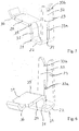
- FIG. 4 clearly visible, showing the electricity meter terminal block 1 with attached electricity meter 2 in the open position of the locking element 28.
- the locking element 28 is pressed against the force of lying between the locking element 28 and the bottom plate 7 compression spring 29 in the direction of the bottom plate 7 through the free end of the associated Brücker knife contact 26 of the bridging element 27.
- the detent recess 30 release and the locking of the associated blade contact 24 is released.
- the Brücker knife contact 26 dips into the contact slot of the fork tines 23 of the fork contact 21 and is thus electrically connected to the associated fork contact 21.
- the electricity meter 2 is removed, it is still possible to ensure an electrically conductive connection of a power supply line 12a coming from the utility with a dedicated power supply line 12b leading to the load by bridging the associated conductor connections 18.
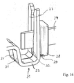
- FIG. 5 Fig. 12 shows a front perspective view of the electricity meter terminal 21 integrally formed with the bus bar 20 in the form of a fork contact.
- the busbar 20 is bent down from a busbar plane opposite to the extension direction of the free ends of the forks 23 (down) in a first section 31.
- a deflection section 22 connects.
- the two mutually parallel fork tines 23 are arranged, the extending transversely to the busbar plane 20 and opposite to the first section 31 upwards.
- a contact slot 32 for receiving an associated blade contact 24 and a Brücker blade contact 26 between the two spaced apart prongs 23 is formed.
- the fork tines 23 have opposing protrusions 33a, 33b for making electrical contact with a blade contact 24 of an electricity meter 2 or a bridge blade contact 26 of a bridging element 27.
- the contact force of the fork contacts 21 acting as a spring force connection is as small as possible Reduced contact point, so as to increase the surface pressure.
- the adjoining the forks 23 section is bisected by a spring slot 34 from each other.
- This spring slot 34 has a much smaller slot width than the contact slot 32. With the help of this spring slot 34 is achieved that adjoining the forks 23 tongue root 35 causes a greater spring force between the forks 23 and the opposing protrusions 33a, 33b.
- the fork end 23 opposite free end of the bus bar 20 also has a protrusion 36 out of the plane of the bus bar 20, so as to create a defined, the smallest possible contact surface for a conductor, so that the clamping force of the clamping spring 19 is concentrated on the contact surface.
- FIG. 6 allows a rear perspective view of the busbar 20 with it integrally formed fork contact 21 recognize. It is clear that the free end of the bus bar 20 adjoining the bulge 36 is bent upward so as to form an inlet slope for insertion of an electrical conductor under the underside of the bus bar 20. It can also be seen that the spaced-apart forks 23 approximately at the level of the busbar plane 20 opposing protrusions 33a for contacting a blade contact 24 of an electricity meter 2 and adjacent to the free end opposing protrusions 33b for electrically conductive contacting a Brücker knife contact 26 have.
- FIG. 7 leaves a front sectional view of the fork contact 21 FIGS. 5 and 6 recognize with inserted blade contact 24 in the section of the deflection section 22.
- the blade contact 24 is transverse to the forks 23 and is inserted over the plane spanned by the forks 23 surface in the contact slot 23.
- the spring slot 34 adjoining the contact slot 32 is slightly bent up by the inserted blade contact 24. This results in that a spring force is exerted on the forks 23 of the adjoining the forks 23 tongue root 35.
- the protrusions 33a rest against the opposing contact surfaces of the blade contact 24 by spring force.
- FIG. 8 shows a perspective view of an electricity meter terminal block 1 with attached electricity meter 2 and with inserted bridging element 27 recognize. It is clear that the bridging element 27 is inserted from above into the bridge openings 11. Incidentally, reference may be made to the above statements.
- the bottom plate 7 by means of fasteners, such as screws 36 z. B. can be mounted on a wall or other support.
- the housing 3 of the electricity meter 2 may have at least one attachment means for mounting the housing 3 on the carrier after being plugged onto the electricity meter terminal block 1.
- FIG. 9 leaves a perspective sectional view of the representation FIG. 8 recognize. It is clear that the Brücker-blade contacts 26 of the bridging element 27 are added when inserting a bridging element 27 in the electricity meter terminal block 1 in the contact slot between the forks 23 of the fork contact 21. Thus, the associated conductor connection is bridged by an electrically conductive cross-connection of the Brücker knife contact 26 with another parallel thereto arranged Brücker knife contact.
- FIG. 10 leaves the situation FIG. 9 recognize as a front sectional view of a fork contact 21 with inserted bridging element 27. It is clear here that the Brücker knife contact 26 has a greater width than the blade contact 24 of the electricity meter 2. When attaching a bridging element 27 and inserting the Brücker knife contact 26 into the contact slot 32 of the contact slot 32 is expanded more than in the case of a merely inserted blade contact 24. As a result, the contact force of the forks 23 is reduced to the blade contact 24 and possibly completely removed, so that the blade contact 24 almost force-free or at least with reduced force removed from the fork contact 21 or inserted into the fork contact 21 when plugging.
- FIG. 11 leaves the situation in accordance FIG. 10 recognize again without inserted blade contact.
- the contact slot below the free end of the Brücker knife contact 26 is now so far expanded by the inserted Brücker knife contact 26 that a low-force or force-free insertion of a blade contact 24 is possible.
- FIG. 12 shows a partial sectional view in the direction of the insertion direction E of a blade contact 24 recognize. It is clear that in the direction of view, ie in the insertion direction E transversely to the insertion direction E a locking element 28 spring loaded by a compression spring 29 is slidably disposed.
- the locking element 28 has a central rectangular receiving opening 37 for receiving and passing a blade contact 24 of an electricity meter 2.
- the forks 23 of the fork contact 21 are arranged. It is clear that they extend transversely to the insertion direction E. In the illustrated locking position, the locking element 28 is displaced by the force of the compression spring 29 of the bottom plate 7 in the direction of free ends of the forks 23.
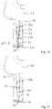
- FIG. 13 has a partial sectional view according to FIG. 12 recognize now with the locking element 28 in the open position.
- the open position is achieved in that an actuating paragraph at the free end of the Brücker knife contact 26 from the top of the upper edge of the locking element 28 abuts and this upon insertion of the Brücker knife contact 26 in the contact slot 32 of the fork contact 21 down against the force of the compression spring 29th relocated.
- FIG. 14 leaves a partial sectional view according to FIG. 13 recognize with now introduced blade contact 24 of an electricity meter 2. It is clear that the receiving opening 37 of the locking element 28 is sufficiently wide and long compared to the cross-section of the blade contact 24, to allow a contact-free passage of the blade contact 24 by the locking element 28.
- FIG. 16 leaves a perspective view of the fork contact 21 with the locking element 28 and inserted blade contact 24 in the locking position according to FIG. 15 recognize. It is clear here that the locking element 28 surrounds the blade contact 24 on all sides and, as out FIG. 15 recognizable, latched at the lower edge of the blade contact 24 by the catch recess 30 of the blade contact 24.
- FIG. 17 leaves a perspective view according to FIG. 16 detect with inserted bridging element 27 with inserted into the clamping slot 32 Brücker knife contact 26.
- the locking member 24 is displaced by the Brücker knife contact 26 downwardly opposite to the free end of the forks 23 directed extension direction of the forks.
- FIG. 18 lets recognize a perspective view of the locking element 28.
- the locking element 28 z. B. is an integrally manufactured plastic part with a central rectangular receiving opening 37.
- a pin 39 for receiving the compression spring 29 is provided on the underside of the locking element 28, a pin 39 for receiving the compression spring 29 is provided.
- the lock member has narrower side edges 41 opposite to the main body 40. These are provided to be received in guide grooves of the insulating case 9 of the electricity meter terminal block 1. In this way it is achieved that the locking element 28 is linearly movable and spring-loaded by the force of the compression spring 29.
- FIG. 19 shows a side sectional view of the electricity meter terminal block 1 with inserted bridging element 27 now recognize without energy meter 2.
- a terminal-contact receiving opening 42 is inserted opposite to the conductor insertion openings 8, which leads through the receiving opening 37 of the locking element 28 to the electricity meter connection terminal in the form of the fork contact 21.
- an actuating shoulder 43 at the free end is present on the bridge knife contact 26 into which the upper edge of the locking element 28 is inserted and by which the locking element 28 is displaced in the direction of the base plate 7 into the open position.
- FIG. 20 shows a perspective view of a first embodiment of an electricity meter 2 with a plurality of juxtaposed and extending parallel to each other blade contacts 24 recognize on one end face. It is clear that all these blade contacts 24 have locking recesses 30 at the bottom. It can be seen further that the guide webs 4 extend parallel to the blade contacts 24 on the same end face for coupling to an electricity meter terminal block 1 at a distance from each other. The guide tabs 4 have a greater length and width than the blade contacts 24 and thus also serve to protect the blade contacts 24 from bending or breaking.
- FIG. 21 leaves the electricity meter 2 off FIG. 20 recognize in the perspective rear view. It is clear that on the front side, which is opposite to the front of the knife contacts 24, a fastening lug 44 is provided, with which the housing 3 of the electricity meter 2 can be screwed onto a support.
- the electricity meter 2 can be mounted on a support with only one screw on the mounting lug 44 fixed because the screw of the electricity meter terminal block 1 due to the connection with the guide plates 4 can be used with for attachment of the electricity meter 2 without undue forces and moments between the electricity meter 2 and electricity meter terminal block 1 act.
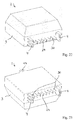
- FIG. 22 shows a perspective view of a second embodiment of an electricity meter 2 in the perspective top view.
- not all knife contacts are provided with locking recesses 30 here. Rather, 24 locking recesses are provided only at the outer two blade contacts. Accordingly, 30 locking elements are provided in the electricity meter terminal block 1 only for these blade contacts 24 with locking recesses.
- FIG. 24 lets recognize a perspective view of a bridging element 27.
- the bridging element 27 has a handle body 45 made of insulating material, are received in the electrically conductive bridge (not visible) between each associated Brücker knife contacts 26.
- two adjacent bridge blade contacts 26 are electrically conductively connected to each other.
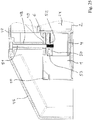
- FIG. 25 shows a partial sectional view of the terminal portion of the electricity meter connection terminal 1 with attached electricity meter 2 and a cover 46.
- the cover 46 completely covers the electricity meter connection terminal 1 and projects with a Abdeckwandung 47 the top of the electricity meter 2 at least partially. It can be seen that the lateral guide tab 4 of the electricity meter 2 is guided under the projection 6 of the electricity meter connection terminal 1.
- a dome 48 is present, which is guided by the Abdeckwandung to the projection 6, when the cover is intended to be placed on the electricity meter connection terminal 1 with attached electricity meter 2.
- In the projection there is an opening 49 into which the dome 48 dips to rest on an upper rib 50 of the guide tongue 4.
- the dome 48 is recognizable configured as a hollow cylinder and provided for receiving a fastening screw 51.
- the fastening screw 51 is screwed to a threaded plate 52 which is installed in a cavity 53 formed in the upper rib 50.
- Alternative other embodiments for forming a threaded nut on the guide plate 4 are conceivable.
- the diameter of the free end of the mandrel 48 is tapered from the remaining portion.
- the length of the tapered free end is longer than the thickness of the projection 6, so that it is ensured that the dome does not rest on the projection 6.
Landscapes
- Physics & Mathematics (AREA)
- General Physics & Mathematics (AREA)
- Connector Housings Or Holding Contact Members (AREA)
- Connections Arranged To Contact A Plurality Of Conductors (AREA)
- Contacts (AREA)
Claims (10)
- Bloc de bornes de connexion de compteur électrique (1), avec un boîtier en matériau isolant (9), avec des connexions conductrices (18) destinées à la connexion de lignes d'alimentation en énergie (12a, 12b) électriques et avec des bornes de connexion de compteur électrique (21) destinées au raccordement électriquement conducteur de connexions conductrices (18) à des contacts de connexion (24) associés d'un compteur électrique (2) reçu par le bloc de bornes de connexion de compteur électrique (1), caractérisé en ce que les bornes de connexion de compteur électrique (21)sont formés en tant que contacts à fourche avec deux dents de fourche (23) raccordées l'une à l'autre par le biais d'une racine de languette (35) commune et appropriées pour une mise en contact d'un contact à couteau (24) d'un compteur électrique (2) associé pouvant être reçu entre les dents de fourche (23), et en ce que le boîtier en matériau isolant (9) a des ouvertures de réception de contacts de connexion (42) destinées à recevoir respectivement un contact de connexion (24) associé d'un compteur électrique (2), les ouvertures de réception de contacts de connexion (42) définissant une direction d'introduction (E) des contacts de connexion (24) dans le boîtier en matériau isolant (9) du bloc de bornes de connexion de compteur électrique (1), et en ce que les bornes de connexion de compteur électrique (21) réalisées en tant que contacts à fourche s'étendent transversalement à la direction d'introduction (E) de contacts à couteau (24) associés qui peuvent être introduits dans une ouverture de réception de contacts de connexion (42) respective.
- Bloc de bornes de connexion de compteur électrique (1) selon la revendication 1, caractérisé en ce que les contacts à fourche (21) sont formés d'un seul tenant avec une barre omnibus (20) pour une connexion conductrice (18) associé.
- Bloc de bornes de connexion de compteur électrique (1) selon la revendication 2, caractérisé en ce que, dans la zone du contact à fourche (21), la barre omnibus (20) est courbe en s'éloignant d'un plan de rail omnibus à l'opposé de la direction d'étendue des extrémités libres des dents de fourche (23) et se transforment, par le biais d'un tronçon de déviation (22), en tronçon des dents de fourche (23) formant une fente de contact (32) pour un contact à couteau (24).
- Bloc de bornes de connexion de compteur électrique (1) selon l'une des revendications 1 à 3, caractérisé en ce que les connexions conductrices (18) sont réalisées en tant que connexions à bornes à ressort.
- Bloc de bornes de connexion de compteur électrique (1) selon l'une des revendications précédentes, caractérisé en ce qu'une fente à ressort (34), plus étroite comparée à la fente de contact (32), est contiguë à une fente de contact (32) formée par les dents de fourche (23) espacées les unes des autres pour la réception d'un contact à couteau (24).
- Bloc de bornes de connexion de compteur électrique (1) selon l'une des revendications précédentes, caractérisé en ce qu'il est prévu au moins un élément de verrouillage (28) destiné au verrouillage du bloc de bornes de connexion de compteur électrique (1) avec un contact de connexion (24) introduit d'un compteur électrique (2).
- Bloc de bornes de connexion de compteur électrique (1) selon l'une des revendications précédentes, caractérisé en ce que le boîtier en matériau isolant (9) a des ouvertures pour éléments de pontage (11) qui sont ouvertes vers les extrémités libres des dents de fourche (23) des contacts à fourche (21) et qui sont destinées à la réception de contacts à couteau d'éléments de pontage (26) d'un élément de shuntage (27) pouvant être reçu par le bloc de bornes de connexion de compteur électrique (1).
- Bloc de bornes de connexion de compteur électrique (1) selon l'une des revendications 6 ou 7, caractérisé en ce que l'élément de verrouillage (28) est un pêne chargé par ressort destiné à plonger dans un creux d'encliquetage (30) d'un contact de connexion (24) introduit d'un compteur électrique (2).
- Bloc de bornes de connexion de compteur électrique (1) selon l'une des revendications précédentes, caractérisé en ce qu'au moins un élément de verrouillage (28) est disposé dans le boîtier en matériau isolant (9) au voisinage d'une borne de connexion de compteur électrique (21) associée, l'élément de verrouillage (28) étant chargé par ressort et pouvant être déplacé par force de ressort à partir d'une position ouverte vers une position de verrouillage et étant prévu pour, dans la position de verrouillage, plonger dans un creux d'encliquetage (30) d'un contact de connexion (24) introduit d'un compteur électrique (2).
- Compteur électrique (2) avec un bloc de bornes de connexion de compteur électrique (1) selon l'une des revendications précédentes, caractérisé en ce que le compteur électrique (2) a des contacts à couteau (24) avec une lame de couteau plate pour la mise en contact d'un contact à fourche (21) associé du bloc de bornes de connexion de compteur électrique (1), au moins un des contacts à couteau (24) ayant un creux d'encliquetage (30) qui est constitué pour l'encliquetage avec un élément de verrouillage (28) d'un bloc de bornes de connexion de compteur électrique (1).
Priority Applications (1)
| Application Number | Priority Date | Filing Date | Title |
|---|---|---|---|
| PL14704582T PL2956780T3 (pl) | 2013-02-15 | 2014-02-14 | Blok zacisku przyłączeniowego licznika energii elektrycznej i licznik energii elektrycznej do tego |
Applications Claiming Priority (2)
| Application Number | Priority Date | Filing Date | Title |
|---|---|---|---|
| DE102013101533.6A DE102013101533B4 (de) | 2013-02-15 | 2013-02-15 | Elektrizitätszähler-Anschlussklemmenblock |
| PCT/EP2014/052883 WO2014125060A2 (fr) | 2013-02-15 | 2014-02-14 | Bloc de bornes de connexion de compteur électrique et compteur électrique correspondant |
Publications (2)
| Publication Number | Publication Date |
|---|---|
| EP2956780A2 EP2956780A2 (fr) | 2015-12-23 |
| EP2956780B1 true EP2956780B1 (fr) | 2019-07-10 |
Family
ID=50112908
Family Applications (1)
| Application Number | Title | Priority Date | Filing Date |
|---|---|---|---|
| EP14704582.7A Active EP2956780B1 (fr) | 2013-02-15 | 2014-02-14 | Bloc de bornes de connexion de compteur électrique et compteur électrique correspondant |
Country Status (4)
| Country | Link |
|---|---|
| EP (1) | EP2956780B1 (fr) |
| DE (1) | DE102013101533B4 (fr) |
| PL (1) | PL2956780T3 (fr) |
| WO (1) | WO2014125060A2 (fr) |
Families Citing this family (14)
| Publication number | Priority date | Publication date | Assignee | Title |
|---|---|---|---|---|
| DE102015107055B3 (de) * | 2015-05-06 | 2016-10-06 | Wago Verwaltungsgesellschaft Mbh | Leiteranschlussklemme |
| DE202015003336U1 (de) | 2015-05-10 | 2016-05-11 | Hans Peter Bauer | Klemmenblock für einen Elektrizitätszähler |
| DE102015013012B4 (de) * | 2015-10-07 | 2024-12-05 | Robert Seidl | Energiezähler-Anschlussklemmenblock mit Überbrückungsvorrichtung |
| EP3296751A1 (fr) * | 2016-09-20 | 2018-03-21 | Semax AG | Compteur d'electricite |
| WO2019081565A2 (fr) * | 2017-10-25 | 2019-05-02 | Weidmüller Interface GmbH & Co. KG | Barrette de raccordement |
| CN107748281B (zh) * | 2017-11-07 | 2023-04-28 | 广东电网有限责任公司揭阳供电局 | 一种具有状态识别的互联回路测试端子 |
| CN110277693B (zh) * | 2019-06-28 | 2020-07-28 | 中电装备山东电子有限公司 | 具有防智能电能表和短接装置误拔结构的智能电能表插座 |
| CN110289522B (zh) * | 2019-06-28 | 2020-07-28 | 中电装备山东电子有限公司 | 具有防智能电能表和短接装置误拔及防触电结构的接插件 |
| DE102020104099B4 (de) * | 2020-02-17 | 2021-10-14 | Klaus Bruchmann Gmbh | Aufnahmeeinheit für Kontaktstift in einem Zähleranschlussblock und System mit einem Zähleranschlussblock und einer Überbrückungsvorrichtung |
| CN113281548B (zh) * | 2021-06-29 | 2023-06-09 | 广东电网有限责任公司 | 一种电表接线端子 |
| CN113740576B (zh) * | 2021-09-10 | 2025-04-08 | 青岛世泽智能科技有限公司 | 一种电能表 |
| CN114778912B (zh) * | 2022-04-25 | 2023-08-11 | 安徽融兆智能有限公司 | 一种电能表 |
| CN116183990B (zh) * | 2023-04-06 | 2025-12-12 | 成都长城开发科技股份有限公司 | 一种电表外置接线柱安装结构 |
| CN117289004B (zh) * | 2023-10-10 | 2025-11-18 | 宁波市全盛壳体有限公司 | 一种模组单元、换表接插组件以及电表组件 |
Family Cites Families (13)
| Publication number | Priority date | Publication date | Assignee | Title |
|---|---|---|---|---|
| US2126602A (en) * | 1935-10-25 | 1938-08-09 | Gen Electric | Electric meter mounting |
| US2154310A (en) * | 1936-01-17 | 1939-04-11 | Gen Electric | Meter connection box |
| US3519976A (en) * | 1967-09-08 | 1970-07-07 | Sola Basic Ind Inc | Disconnect for electric meters |
| DE2256373C3 (de) * | 1972-11-17 | 1981-09-03 | Christian Geyer GmbH & Co, 8500 Nürnberg | Anschlußklemmenblock mit Steckverbindungsteil für mit feststehenden Steckerstiften versehene Elektrizitätszähler |
| DE4113328A1 (de) * | 1991-04-24 | 1992-10-29 | Geyer Gmbh & Co Christian | Zaehlersteckklemme |
| DE19613869C2 (de) * | 1996-04-06 | 1999-01-28 | Geyer Ag | Zählersteckklemme |
| DE19621816A1 (de) * | 1996-04-27 | 1997-10-30 | Willi Hoffmann | Steckverbinder für die aufhebbare elektrische Verbindung zwischen einem elektrischen Gerät und elektrischen Anschlüssen |
| CA2237397C (fr) * | 1997-05-30 | 2002-10-01 | Ekstrom Industries, Inc. | Contact a machoire d'adaptateur de socle de wattheuremetre |
| DE10216913A1 (de) * | 2001-09-12 | 2003-05-22 | Hager Electro Gmbh | Anschlussleiste |
| JP4100282B2 (ja) * | 2003-08-08 | 2008-06-11 | 住友電装株式会社 | 音叉状端子のスリット幅検査部を備えた電気接続箱 |
| DE102008045810B4 (de) * | 2008-09-05 | 2010-09-02 | Tyco Electronics Amp Gmbh | Elektrischer Gabelkontakt für ein Stanzgitter, sowie elektrisches Stanzgitter |
| DE102010032038A1 (de) * | 2010-07-23 | 2012-01-26 | Hager Electro Gmbh & Co. Kg | Zählerplatzbaugruppe |
| DE102011015697B4 (de) * | 2011-03-31 | 2015-03-26 | Klaus Bruchmann Gmbh | Zählerschaltblock für einen Elektrizitätszähler sowie Vorrichtungen mit einem Zählerschaltblock |
-
2013
- 2013-02-15 DE DE102013101533.6A patent/DE102013101533B4/de not_active Expired - Fee Related
-
2014
- 2014-02-14 PL PL14704582T patent/PL2956780T3/pl unknown
- 2014-02-14 WO PCT/EP2014/052883 patent/WO2014125060A2/fr not_active Ceased
- 2014-02-14 EP EP14704582.7A patent/EP2956780B1/fr active Active
Non-Patent Citations (1)
| Title |
|---|
| None * |
Also Published As
| Publication number | Publication date |
|---|---|
| DE102013101533B4 (de) | 2017-05-11 |
| EP2956780A2 (fr) | 2015-12-23 |
| PL2956780T3 (pl) | 2019-12-31 |
| WO2014125060A2 (fr) | 2014-08-21 |
| DE102013101533A1 (de) | 2014-08-21 |
| WO2014125060A3 (fr) | 2014-10-09 |
Similar Documents
| Publication | Publication Date | Title |
|---|---|---|
| DE102013101533B4 (de) | Elektrizitätszähler-Anschlussklemmenblock | |
| EP3298659B1 (fr) | Borne de connexion de conducteur | |
| EP3476007B1 (fr) | Borne de connexion de conducteur | |
| EP3100058B1 (fr) | Système de raccordement de compteur électrique et fiche de court-circuit ainsi que fiche isolante | |
| EP2255369B1 (fr) | Borne serre-fil, en particulier borne sectionnable | |
| EP2306594B1 (fr) | Adaptateur de raccordement | |
| EP2546856B1 (fr) | Baguette pour fusibles NH | |
| DE102008057754B4 (de) | Baueinheit aus mindestens zwei nebeneinander angeordneten Trennklemmen und mindestens zwei miteinander verbundenen Anschlusssteckern | |
| DE102010010260C9 (de) | Steckverbinder | |
| WO1996009664A1 (fr) | Borne de connexion pour installations electriques | |
| DE202011108572U1 (de) | Adapter und Set aus Reihenklemme und Adapter | |
| DE102010015011B4 (de) | Brücker für elektrische Klemmen und Reihenklemmenanordnung mit einem Brücker | |
| EP4273561B1 (fr) | Borne électrique à ressort pour borne enfichable de compteur | |
| DE102011101078B4 (de) | Elektrisches Installationsschaltgerät mit einer Schnellbefestigungsvorrichtung | |
| AT517769A2 (de) | Energiezähler-Anschlussklemmenblock mit Überbrückungsvorrichtung | |
| EP3698440B1 (fr) | Pince de fixation | |
| EP1961091A1 (fr) | Appareillage d' installation électrique | |
| EP2874250B1 (fr) | Appareil d'installation électrique | |
| EP2489100B1 (fr) | Borne à vis avec couvercle et appareil de coupure d'installation | |
| EP2325949B1 (fr) | Dispositif de connexion pour un compteur électronique d'électricité | |
| EP1657555B1 (fr) | Support pour connecter un compteur électrique | |
| EP1253610B1 (fr) | Adaptateur pour contacter des sectionneurs de coupure en charge sur barres omnibus | |
| EP2874251B1 (fr) | Appareil d'installation électrique | |
| CH715071B1 (de) | Verbrauchszähler mit Leiteranschlussvorrichtung. | |
| DE102024131969A1 (de) | Anschlussklemme zum Anschließen einer elektrischen Leitung |
Legal Events
| Date | Code | Title | Description |
|---|---|---|---|
| PUAI | Public reference made under article 153(3) epc to a published international application that has entered the european phase |
Free format text: ORIGINAL CODE: 0009012 |
|
| 17P | Request for examination filed |
Effective date: 20150608 |
|
| AK | Designated contracting states |
Kind code of ref document: A2 Designated state(s): AL AT BE BG CH CY CZ DE DK EE ES FI FR GB GR HR HU IE IS IT LI LT LU LV MC MK MT NL NO PL PT RO RS SE SI SK SM TR |
|
| AX | Request for extension of the european patent |
Extension state: BA ME |
|
| DAX | Request for extension of the european patent (deleted) | ||
| STAA | Information on the status of an ep patent application or granted ep patent |
Free format text: STATUS: EXAMINATION IS IN PROGRESS |
|
| 17Q | First examination report despatched |
Effective date: 20180117 |
|
| REG | Reference to a national code |
Ref country code: DE Ref legal event code: R079 Ref document number: 502014012172 Country of ref document: DE Free format text: PREVIOUS MAIN CLASS: G01R0011040000 Ipc: H01R0013030000 |
|
| GRAP | Despatch of communication of intention to grant a patent |
Free format text: ORIGINAL CODE: EPIDOSNIGR1 |
|
| RIC1 | Information provided on ipc code assigned before grant |
Ipc: H01R 13/03 20060101AFI20181126BHEP Ipc: H01R 9/24 20060101ALI20181126BHEP Ipc: G01R 11/04 20060101ALI20181126BHEP Ipc: H01R 13/11 20060101ALI20181126BHEP |
|
| STAA | Information on the status of an ep patent application or granted ep patent |
Free format text: STATUS: GRANT OF PATENT IS INTENDED |
|
| INTG | Intention to grant announced |
Effective date: 20190103 |
|
| GRAJ | Information related to disapproval of communication of intention to grant by the applicant or resumption of examination proceedings by the epo deleted |
Free format text: ORIGINAL CODE: EPIDOSDIGR1 |
|
| STAA | Information on the status of an ep patent application or granted ep patent |
Free format text: STATUS: EXAMINATION IS IN PROGRESS |
|
| GRAS | Grant fee paid |
Free format text: ORIGINAL CODE: EPIDOSNIGR3 |
|
| STAA | Information on the status of an ep patent application or granted ep patent |
Free format text: STATUS: GRANT OF PATENT IS INTENDED |
|
| GRAP | Despatch of communication of intention to grant a patent |
Free format text: ORIGINAL CODE: EPIDOSNIGR1 |
|
| INTC | Intention to grant announced (deleted) | ||
| INTG | Intention to grant announced |
Effective date: 20190425 |
|
| GRAA | (expected) grant |
Free format text: ORIGINAL CODE: 0009210 |
|
| STAA | Information on the status of an ep patent application or granted ep patent |
Free format text: STATUS: THE PATENT HAS BEEN GRANTED |
|
| AK | Designated contracting states |
Kind code of ref document: B1 Designated state(s): AL AT BE BG CH CY CZ DE DK EE ES FI FR GB GR HR HU IE IS IT LI LT LU LV MC MK MT NL NO PL PT RO RS SE SI SK SM TR |
|
| REG | Reference to a national code |
Ref country code: GB Ref legal event code: FG4D Free format text: NOT ENGLISH |
|
| REG | Reference to a national code |
Ref country code: CH Ref legal event code: EP Ref country code: AT Ref legal event code: REF Ref document number: 1154498 Country of ref document: AT Kind code of ref document: T Effective date: 20190715 |
|
| REG | Reference to a national code |
Ref country code: IE Ref legal event code: FG4D Free format text: LANGUAGE OF EP DOCUMENT: GERMAN |
|
| REG | Reference to a national code |
Ref country code: DE Ref legal event code: R096 Ref document number: 502014012172 Country of ref document: DE |
|
| REG | Reference to a national code |
Ref country code: NL Ref legal event code: MP Effective date: 20190710 |
|
| REG | Reference to a national code |
Ref country code: LT Ref legal event code: MG4D |
|
| PG25 | Lapsed in a contracting state [announced via postgrant information from national office to epo] |
Ref country code: NO Free format text: LAPSE BECAUSE OF FAILURE TO SUBMIT A TRANSLATION OF THE DESCRIPTION OR TO PAY THE FEE WITHIN THE PRESCRIBED TIME-LIMIT Effective date: 20191010 Ref country code: FI Free format text: LAPSE BECAUSE OF FAILURE TO SUBMIT A TRANSLATION OF THE DESCRIPTION OR TO PAY THE FEE WITHIN THE PRESCRIBED TIME-LIMIT Effective date: 20190710 Ref country code: SE Free format text: LAPSE BECAUSE OF FAILURE TO SUBMIT A TRANSLATION OF THE DESCRIPTION OR TO PAY THE FEE WITHIN THE PRESCRIBED TIME-LIMIT Effective date: 20190710 Ref country code: HR Free format text: LAPSE BECAUSE OF FAILURE TO SUBMIT A TRANSLATION OF THE DESCRIPTION OR TO PAY THE FEE WITHIN THE PRESCRIBED TIME-LIMIT Effective date: 20190710 Ref country code: LT Free format text: LAPSE BECAUSE OF FAILURE TO SUBMIT A TRANSLATION OF THE DESCRIPTION OR TO PAY THE FEE WITHIN THE PRESCRIBED TIME-LIMIT Effective date: 20190710 Ref country code: BG Free format text: LAPSE BECAUSE OF FAILURE TO SUBMIT A TRANSLATION OF THE DESCRIPTION OR TO PAY THE FEE WITHIN THE PRESCRIBED TIME-LIMIT Effective date: 20191010 Ref country code: PT Free format text: LAPSE BECAUSE OF FAILURE TO SUBMIT A TRANSLATION OF THE DESCRIPTION OR TO PAY THE FEE WITHIN THE PRESCRIBED TIME-LIMIT Effective date: 20191111 Ref country code: NL Free format text: LAPSE BECAUSE OF FAILURE TO SUBMIT A TRANSLATION OF THE DESCRIPTION OR TO PAY THE FEE WITHIN THE PRESCRIBED TIME-LIMIT Effective date: 20190710 |
|
| PG25 | Lapsed in a contracting state [announced via postgrant information from national office to epo] |
Ref country code: AL Free format text: LAPSE BECAUSE OF FAILURE TO SUBMIT A TRANSLATION OF THE DESCRIPTION OR TO PAY THE FEE WITHIN THE PRESCRIBED TIME-LIMIT Effective date: 20190710 Ref country code: ES Free format text: LAPSE BECAUSE OF FAILURE TO SUBMIT A TRANSLATION OF THE DESCRIPTION OR TO PAY THE FEE WITHIN THE PRESCRIBED TIME-LIMIT Effective date: 20190710 Ref country code: LV Free format text: LAPSE BECAUSE OF FAILURE TO SUBMIT A TRANSLATION OF THE DESCRIPTION OR TO PAY THE FEE WITHIN THE PRESCRIBED TIME-LIMIT Effective date: 20190710 Ref country code: RS Free format text: LAPSE BECAUSE OF FAILURE TO SUBMIT A TRANSLATION OF THE DESCRIPTION OR TO PAY THE FEE WITHIN THE PRESCRIBED TIME-LIMIT Effective date: 20190710 Ref country code: GR Free format text: LAPSE BECAUSE OF FAILURE TO SUBMIT A TRANSLATION OF THE DESCRIPTION OR TO PAY THE FEE WITHIN THE PRESCRIBED TIME-LIMIT Effective date: 20191011 Ref country code: IS Free format text: LAPSE BECAUSE OF FAILURE TO SUBMIT A TRANSLATION OF THE DESCRIPTION OR TO PAY THE FEE WITHIN THE PRESCRIBED TIME-LIMIT Effective date: 20191110 |
|
| PG25 | Lapsed in a contracting state [announced via postgrant information from national office to epo] |
Ref country code: TR Free format text: LAPSE BECAUSE OF FAILURE TO SUBMIT A TRANSLATION OF THE DESCRIPTION OR TO PAY THE FEE WITHIN THE PRESCRIBED TIME-LIMIT Effective date: 20190710 |
|
| PG25 | Lapsed in a contracting state [announced via postgrant information from national office to epo] |
Ref country code: IT Free format text: LAPSE BECAUSE OF FAILURE TO SUBMIT A TRANSLATION OF THE DESCRIPTION OR TO PAY THE FEE WITHIN THE PRESCRIBED TIME-LIMIT Effective date: 20190710 Ref country code: RO Free format text: LAPSE BECAUSE OF FAILURE TO SUBMIT A TRANSLATION OF THE DESCRIPTION OR TO PAY THE FEE WITHIN THE PRESCRIBED TIME-LIMIT Effective date: 20190710 Ref country code: DK Free format text: LAPSE BECAUSE OF FAILURE TO SUBMIT A TRANSLATION OF THE DESCRIPTION OR TO PAY THE FEE WITHIN THE PRESCRIBED TIME-LIMIT Effective date: 20190710 Ref country code: EE Free format text: LAPSE BECAUSE OF FAILURE TO SUBMIT A TRANSLATION OF THE DESCRIPTION OR TO PAY THE FEE WITHIN THE PRESCRIBED TIME-LIMIT Effective date: 20190710 |
|
| PG25 | Lapsed in a contracting state [announced via postgrant information from national office to epo] |
Ref country code: CZ Free format text: LAPSE BECAUSE OF FAILURE TO SUBMIT A TRANSLATION OF THE DESCRIPTION OR TO PAY THE FEE WITHIN THE PRESCRIBED TIME-LIMIT Effective date: 20190710 Ref country code: SM Free format text: LAPSE BECAUSE OF FAILURE TO SUBMIT A TRANSLATION OF THE DESCRIPTION OR TO PAY THE FEE WITHIN THE PRESCRIBED TIME-LIMIT Effective date: 20190710 Ref country code: IS Free format text: LAPSE BECAUSE OF FAILURE TO SUBMIT A TRANSLATION OF THE DESCRIPTION OR TO PAY THE FEE WITHIN THE PRESCRIBED TIME-LIMIT Effective date: 20200224 Ref country code: SK Free format text: LAPSE BECAUSE OF FAILURE TO SUBMIT A TRANSLATION OF THE DESCRIPTION OR TO PAY THE FEE WITHIN THE PRESCRIBED TIME-LIMIT Effective date: 20190710 |
|
| REG | Reference to a national code |
Ref country code: DE Ref legal event code: R097 Ref document number: 502014012172 Country of ref document: DE |
|
| PLBE | No opposition filed within time limit |
Free format text: ORIGINAL CODE: 0009261 |
|
| STAA | Information on the status of an ep patent application or granted ep patent |
Free format text: STATUS: NO OPPOSITION FILED WITHIN TIME LIMIT |
|
| PG2D | Information on lapse in contracting state deleted |
Ref country code: IS |
|
| 26N | No opposition filed |
Effective date: 20200603 |
|
| PG25 | Lapsed in a contracting state [announced via postgrant information from national office to epo] |
Ref country code: SI Free format text: LAPSE BECAUSE OF FAILURE TO SUBMIT A TRANSLATION OF THE DESCRIPTION OR TO PAY THE FEE WITHIN THE PRESCRIBED TIME-LIMIT Effective date: 20190710 |
|
| REG | Reference to a national code |
Ref country code: DE Ref legal event code: R119 Ref document number: 502014012172 Country of ref document: DE |
|
| REG | Reference to a national code |
Ref country code: CH Ref legal event code: PL |
|
| GBPC | Gb: european patent ceased through non-payment of renewal fee |
Effective date: 20200214 |
|
| REG | Reference to a national code |
Ref country code: BE Ref legal event code: MM Effective date: 20200229 |
|
| PG25 | Lapsed in a contracting state [announced via postgrant information from national office to epo] |
Ref country code: LU Free format text: LAPSE BECAUSE OF NON-PAYMENT OF DUE FEES Effective date: 20200214 Ref country code: MC Free format text: LAPSE BECAUSE OF FAILURE TO SUBMIT A TRANSLATION OF THE DESCRIPTION OR TO PAY THE FEE WITHIN THE PRESCRIBED TIME-LIMIT Effective date: 20190710 |
|
| PG25 | Lapsed in a contracting state [announced via postgrant information from national office to epo] |
Ref country code: LI Free format text: LAPSE BECAUSE OF NON-PAYMENT OF DUE FEES Effective date: 20200229 Ref country code: CH Free format text: LAPSE BECAUSE OF NON-PAYMENT OF DUE FEES Effective date: 20200229 |
|
| PG25 | Lapsed in a contracting state [announced via postgrant information from national office to epo] |
Ref country code: IE Free format text: LAPSE BECAUSE OF NON-PAYMENT OF DUE FEES Effective date: 20200214 Ref country code: DE Free format text: LAPSE BECAUSE OF NON-PAYMENT OF DUE FEES Effective date: 20200901 Ref country code: GB Free format text: LAPSE BECAUSE OF NON-PAYMENT OF DUE FEES Effective date: 20200214 Ref country code: FR Free format text: LAPSE BECAUSE OF NON-PAYMENT OF DUE FEES Effective date: 20200229 |
|
| PG25 | Lapsed in a contracting state [announced via postgrant information from national office to epo] |
Ref country code: BE Free format text: LAPSE BECAUSE OF NON-PAYMENT OF DUE FEES Effective date: 20200229 |
|
| REG | Reference to a national code |
Ref country code: AT Ref legal event code: MM01 Ref document number: 1154498 Country of ref document: AT Kind code of ref document: T Effective date: 20200214 |
|
| PG25 | Lapsed in a contracting state [announced via postgrant information from national office to epo] |
Ref country code: AT Free format text: LAPSE BECAUSE OF NON-PAYMENT OF DUE FEES Effective date: 20200214 |
|
| PG25 | Lapsed in a contracting state [announced via postgrant information from national office to epo] |
Ref country code: MT Free format text: LAPSE BECAUSE OF FAILURE TO SUBMIT A TRANSLATION OF THE DESCRIPTION OR TO PAY THE FEE WITHIN THE PRESCRIBED TIME-LIMIT Effective date: 20190710 Ref country code: CY Free format text: LAPSE BECAUSE OF FAILURE TO SUBMIT A TRANSLATION OF THE DESCRIPTION OR TO PAY THE FEE WITHIN THE PRESCRIBED TIME-LIMIT Effective date: 20190710 |
|
| PG25 | Lapsed in a contracting state [announced via postgrant information from national office to epo] |
Ref country code: MK Free format text: LAPSE BECAUSE OF FAILURE TO SUBMIT A TRANSLATION OF THE DESCRIPTION OR TO PAY THE FEE WITHIN THE PRESCRIBED TIME-LIMIT Effective date: 20190710 |
|
| PGFP | Annual fee paid to national office [announced via postgrant information from national office to epo] |
Ref country code: PL Payment date: 20260203 Year of fee payment: 13 |