EP2956809B1 - Ensemble câble à fibres optiques - Google Patents
Ensemble câble à fibres optiques Download PDFInfo
- Publication number
- EP2956809B1 EP2956809B1 EP14708983.3A EP14708983A EP2956809B1 EP 2956809 B1 EP2956809 B1 EP 2956809B1 EP 14708983 A EP14708983 A EP 14708983A EP 2956809 B1 EP2956809 B1 EP 2956809B1
- Authority
- EP
- European Patent Office
- Prior art keywords
- assembly
- trunk
- strength members
- optical fibers
- tube
- Prior art date
- Legal status (The legal status is an assumption and is not a legal conclusion. Google has not performed a legal analysis and makes no representation as to the accuracy of the status listed.)
- Active
Links
Images




Classifications
-
- G—PHYSICS
- G02—OPTICS
- G02B—OPTICAL ELEMENTS, SYSTEMS OR APPARATUS
- G02B6/00—Light guides; Structural details of arrangements comprising light guides and other optical elements, e.g. couplings
- G02B6/44—Mechanical structures for providing tensile strength and external protection for fibres, e.g. optical transmission cables
- G02B6/4439—Auxiliary devices
- G02B6/4471—Terminating devices ; Cable clamps
- G02B6/4472—Manifolds
Definitions
- aspects of the present disclosure relate generally to fiber optic cable assemblies. More specifically, aspects of the present disclosure relate to a robust cable assembly that includes a trunk cable joined with a plurality of leg cables.
- Cable assemblies may be used to branch optical fibers from a trunk cable to a plurality of leg cables.
- manufacture of cable assemblies may be cumbersome.
- optical fibers of the trunk cable are typically individually routed through furcation tubes that become the leg cables, which may be particularly time-consuming. Connectors are then attached, often manually, to distal ends of the leg cables.
- cable assemblies may be less robust than the associated cables.
- reinforcement components of the cables may simply be glued to the assemblies, where the pull-out strength of the individual leg cables is directly related to the strength of the glue, as opposed to the reinforcement components of the leg cables.
- US 2012/230636 A1 discloses a cable assembly according to the prior art, namely a cable assembly including a connector device for connecting a first fiber optic cable to a plurality of second fiber optic cables.
- US 2010/0086260 A1 show additional prior art.
- the invention provides a cable assembly according to claim 1.
- a fiber optic cable assembly which includes leg assemblies, a trunk assembly, a splice assembly, and a furcation assembly.
- Each leg assembly includes a jacket, an optical fiber, strength members, and a connector.
- the trunk assembly includes a jacket, optical fibers, strength members, and a multi-fiber connector.
- the splice assembly includes a tube where spliced optical fibers of the leg and trunk assemblies are located. Splicing the optical fibers of the individual leg cables to those of the trunk cable, instead of using continuous optical fibers from the trunk cable to form the leg cables, allows use of pigtails for the leg assemblies and/or trunk assembly that have been separately pre-assembled and/or pre-terminated, such as by an automated process.
- the furcation assembly is attached to the splice assembly and includes a fan-out structure and first and second locks.
- the first lock binds the strength members of the leg assemblies to the furcation assembly
- the second lock binds the strength members of the trunk to the furcation assembly.
- a cable assembly which includes leg assemblies, a trunk assembly, and a furcation assembly.
- Each leg assembly includes a jacket, an optical fiber radially surrounded by the jacket and extending lengthwise therethrough, strength members reinforcing both the jacket and the optical fiber, and a fiber optic connector supporting the optical fiber.
- the strength members of the leg assemblies are loose strength members in the form of fibrous strength members that provide tensile strength to the leg assemblies.
- the trunk assembly includes a jacket, a plurality of optical fibers radially surrounded by the jacket and extending lengthwise therethrough, and strength members reinforcing both the jacket and plurality of optical fibers.
- the strength members of the trunk assembly are rigid strength members in the form of rod strength members that provide tensile reinforcement as well as anti-buckling support for the trunk assembly.
- the furcation assembly includes a fan-out structure and first and second locks.
- the optical fibers of the leg assemblies extend through the fan-out structure and into the jacket of the respective leg assembly.
- the first lock binds the fibrous strength members of the leg assemblies to the furcation assembly, and the second lock binds the rod strength members of the trunk to the furcation assembly, directly or indirectly by way of intermediate strength members.
- the furcation assembly provides a mechanical linkage between the trunk and leg assemblies.
- a cable assembly which includes a splice assembly and a furcation assembly.
- the splice assembly includes a tube sized to support a plurality of spliced optical fibers therein.
- the tube is elongate, having a length of at least five times the average width thereof.
- the furcation assembly is attached to the splice assembly on an end of the tube.
- the furcation assembly includes a fan-out structure through which optical fibers of leg assemblies may extend, a first lock configured to bind fibrous strength members, and a second lock configured to bind rigid strength members.
- the furcation is configured to provide a mechanical linkage between the fibrous and rigid strength members.
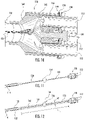
- a fiber optic cable assembly 110 includes leg assemblies 112, a trunk assembly 114, a splice assembly 116, and a furcation assembly 118.
- each leg assembly 112 includes a jacket 120, an optical fiber 122, strength members 124, and a connector 126.
- the jacket 120 of the leg assembly 112 is a polymeric jacket, such as including polyvinyl chloride, medium- or high-density polyethylene, fire-retardant additives, carbon black, and/or other materials.
- FIG. 1 a polymeric jacket, such as including polyvinyl chloride, medium- or high-density polyethylene, fire-retardant additives, carbon black, and/or other materials.
- the jacket 120 is round in cross-section and has a diameter of less than 10 mm, such as less than 8 mm, allowing the leg assembly 112 to maneuver in narrower ducts without preferential bending.
- the jacket 120 is otherwise shaped.
- the leg assemblies 112 may include a buffer tube surrounding the optical fiber 122, partitioning the optical fiber 122 from the strength members 124 interior to the jacket 120.
- the optical fiber 122 of the leg assembly 112 is a high-performance optical fiber, such as a bend-insensitive optical fiber.
- a high-performance optical fiber such as a bend-insensitive optical fiber.
- the optical fiber 122 when wrapped one turn around a 10 mm diameter mandrel, the optical fiber 122 exhibits a bend-induced change in optical attenuation of less than 0.5 dB at an 850 nm wavelength, such as less than 0.4 dB, such as less than 0.25 dB.
- High performing optical fibers such as CLEARCURVE TM fibers manufactured by Corning Incorporated of Corning, New York, allow the leg assembly 112 to be easily routed into and through equipment, ducts, and elsewhere.
- the optical fiber 122 may be a single-mode optical fiber, a multi-mode optical fiber, a multi-core optical fiber, tight-buffered optical fibers, and/or another type of optical fiber.
- each leg assembly 112 may include more than one optical fiber 122, such as two optical fibers each or other numbers of optical fibers.
- the connector 126 of the leg assembly 112 supports (i.e., uses, incorporates) the optical fiber 122.
- the optical fiber 122 may be cleaved, fixed to a ferrule of the connector 126, laser- or machine-polished/shaped, and protected in a rugged, weatherproof connector housing (as shown in FIG. 1 ).
- the connector 126 is an SC-type connector, in other embodiments the connector 126 is an LC-type (duplex) connector, and in still other embodiments the connector 126 is an MPO-type connector. In contemplated embodiments, other types of connectors 126 are used.
- the connector 126 may be a single-fiber connector or a multi-fiber connector.
- the trunk assembly 114 includes a jacket 128, optical fibers 130, strength members 132, and a multi-fiber connector 134. Similar to the jacket 120 of the leg assemblies 112, in some embodiments the jacket 128 of the trunk assembly 114 is a polymeric jacket, such as including polyvinyl chloride, medium- or high-density polyethylene, fire-retardant additives, carbon black, and/or other materials.
- the jacket 128 of the trunk assembly 114 may have flat exterior sides, as shown in FIG. 1B , or may be round or otherwise shaped.
- the jacket 128 of the trunk assembly 114 forms an interior cavity 133 within which the optical fibers 130 are positioned.
- the cavity 133 may be rectangular to guide movement of the optical fibers 130 as the trunk assembly 114 bends, such as where the optical fibers 130 are loosely positioned in the cavity 133 without a buffer tube.
- buffer tubes and/or strength members e.g., aramid
- the cable of the trunk assembly as shown in FIG. 1A including the jacket 128, strength members 132, and optical fibers 130, as well as the cable of the leg assemblies as shown in FIG.
- the jacket 120, strength members 124, and optical fiber 122 may be a gel-filled cable, where a petroleum-based gel or other filler surrounds the optical fibers 122, 130 for water-blocking and coupling of the optical fibers 122, 130 to the respective cables; or the cables may be gel-free ("dry"), including a super-absorbent powder, which may be positioned in open spaces of the cables, alone or integrated with yarn, and used to expand when exposed to water, to block flow of the water through the respective cable.
- dry including a super-absorbent powder
- the trunk assembly 114 may be significantly longer than the leg assemblies 122, such as five or even ten times longer or more.
- the trunk assemblies 114 may span a large distance, such as portion of an outdoor communications antenna, while the leg assemblies 112 may extend into antenna equipment.
- the trunk assembly 114 includes an aerial cable between the splice assembly 116 and the connector 134 that is self-supporting along a span of at least 50 meters under National Electrical Safety Code (NESC) light-loading conditions at 1% installation sag, such as at least 60 meters, and/or at least 75 meters at 1% installation sag.
- NSC National Electrical Safety Code
- the optical fibers 130 are part of a fiber optic ribbon, such as a side-by-side arrangement of a plurality of optical fibers bound to one another by a common matrix (e.g., ultra-violet cured acrylate).
- the fiber optic ribbon is a twelve-fiber ribbon, a four-fiber ribbon, a six-fiber ribbon, a twelve-fiber ribbon.
- the trunk cable includes a stack of ribbons.
- the optical fibers 130 of the trunk assembly 114 are loosely arranged therein, and may be located in one or more buffer tubes. The buffer tubes may be gel-filled or gel-free.
- the number of leg assemblies of the cable assembly is a multiple of the number of optical fibers in the trunk assembly.
- the individual optical fibers of the trunk assembly may be single-mode, multi-mode, multi-core, tight-buffered optical fibers, bend-insensitive, or other types of optical fibers.
- the multi-fiber connector 134 of the trunk assembly 114 supports (i.e., uses, incorporates) some or all of the optical fibers 130 of the trunk assembly 114.
- the optical fiber 122 may be cleaved together in the multi-fiber connector 134, fixed to a ferrule of the connector 134, laser- or machine-polished/shaped, and protected in a rugged, weatherproof connector housing (as shown in FIG. 1 ).
- the multi-fiber connector 134 is an MPO-type connector, such as an MTP ® connector manufactured by US Conec Ltd of Hickory, North Carolina. In contemplated embodiments, another type of connector is used.
- the optical fibers 122, 130 of the leg and trunk assemblies 112, 114 are spliced together at splice points 164.
- the optical fibers 122, 130 are preferably fusion spliced together but may be otherwise spliced.
- the splice assembly includes 116 a tube 136 ( FIG. 12 ) sized to support a plurality of spliced optical fibers 122, 130 of the leg and trunk assemblies 112, 114.
- the tube 136 is elongate, having a length L of at least ten times the average width W thereof.
- the tube may be cylindrical or otherwise shaped and may be formed from a polymer, such as a clear plastic.
- multiple overlapping tubes are used, where the innermost tube supports the spliced optical fibers, and epoxy or another filler may be used to fill space between the innermost tube and one or more tubes exterior thereto (essentially providing a thicker composite tube).
- Splice protectors such as UV-cured acrylate encapsulant and/or splints, may be used to reinforce the splice points 164.
- the interior of the tube 136 in some embodiments, is left with open space (e.g., at least 50% of the interior volume is air) and the tube 136 serves to isolate the spliced optical fibers 122, 130 from other parts of the cable assembly 110, such as the encapsulant 138 as shown in FIG. 14 and discussed below, and the strength members 132, 140 as shown in FIG. 15 .
- the open space in the tube 136 allows the spliced optical fibers 122, 130 to move within the tube 136, such as moving to a neutral axis as the cable assembly 110 bends, or to translate within the tube 136 to accommodate strain on either the trunk or leg assemblies 114, 112.
- the optical fibers 122, 130 in the tube 136 have excess length relative to the length L of the tube 136 (e.g., at least 0.5% longer, at least 1.5% longer), which allows the tube 136 to stretch without straining the spliced optical fibers 122, 130, such as if the cable assembly 110 is axially loaded in tension. Also, contraction of the cable assembly 110, such as in cold weather, has little to no impact on the spliced optical fibers 122, 130 within the tube 136, which are free to bend and buckle in the open space of the tube 136 of the splice assembly 116.
- the tube 136 is filled with a potting material, such as epoxy, which may further protect the spliced fibers 122, 130 therein by encapsulation and/or improve the weather-ability of the cable assembly 110.
- Splicing the optical fibers 122 of the individual leg assemblies 112 to the plurality of optical fibers 130 of the trunk assembly 114 allows for use of pre-terminated pigtails (i.e., short lengths of cable with connectorized ends) that have been separately pre-assembled, such as by an automated process.
- pre-terminated pigtails i.e., short lengths of cable with connectorized ends
- one or more of the optical fibers 122 of the leg assemblies 112 are direct continuations of optical fibers 130 of the trunk assembly 114, not spliced thereto.
- the furcation assembly 118 is attached to the splice assembly 116 (see FIGS. 1 and 12 ) and includes a fan-out structure 142 and first and second locks 144, 146.
- the fan-out structure includes openings 158 for receiving individual leg assemblies 112.
- the furcation assembly 118 further includes a funnel 160 that connects to or is integrally formed with the fan-out structure 142 to direct the optical fibers 122 of the leg assemblies 112 toward the splice assembly 116 and/or to support attachment of the splice assembly 116 to the furcation assembly 118.
- the openings 158 of the fan-out structure 142 may be used, depending upon the number of leg assemblies 112 of the particular cable assembly 110.
- one fan-out structure 142 may support three leg assemblies 112, while another supports six leg assemblies 112.
- the openings 158 may be tiered or tapered lengthwise therethrough, such as by having a stair-step profile, which allows different jacket 120 sizes to be inserted into the same fan-out structure 142.
- different size leg assemblies 112 may be used with the same furcation assembly 118 (e.g., wider and narrower jackets 120; differently shaped jackets 120, 220).
- a hybrid cable assembly as discussed below, may include both wider leg assemblies 112 that support conductive members and narrower leg assemblies 112 that support optical fibers 122.
- the first lock 144 binds the strength members 124 of the leg assemblies 112 to the furcation assembly 118
- the second lock 146 binds the strength members 132 of the trunk 114 to the furcation assembly 118.
- the furcation assembly 118 provides a robust mechanical linkage between the trunk and leg assemblies 112, 114 to strain relieve the spliced optical fibers 122, 132 in the tube 136.
- the cable assembly 110 can support at least 222.4 N (50 lbf) of pulling force, such as at least 444.8 N (100 lbf) or even at least about 667.2 N (150 lbf) of pulling force, without permanently damaging the cable assembly 110, such as (i) without pulling out of the leg assembly 112 from the furcation assembly 118, (ii) without pulling the trunk assembly 114 apart from the splice assembly 116, (iii) without fracturing of the optical fibers 122, 132 of the trunk or leg assemblies 114, 112, and/or (iv) without severing the splice of the spliced optical fibers 122, 132 in the tube 136 of the splice assembly 116.
- the strength members 124 of the leg assemblies 112 are loose strength members (e.g., not bound together in a cured matrix) in the form of fibrous strength members that provide tensile strength to the leg assemblies 112.
- the strength members 124 of the leg assemblies 112 include tensile fibers, such as dielectric aramid and/or fiberglass fibers.
- the fibrous strength members 124 may be arranged as yarns of such tensile fibers; which may, in some embodiments, be stranded around the optical fibers 122.
- the strength members 132 of the trunk assembly 114 are rigid strength members in the form of rod strength members (e.g., beams, rigid wires) that provide anti-buckling support for the trunk assembly 114 as well as tensile reinforcement to the trunk assembly 114.
- the strength members 132 of the trunk assembly 114 include metallic rods or dielectric, glass-reinforced plastic rods.
- strength member of the leg assemblies 112 are rigid strength members, or include rigid strength members.
- one or more of the leg assemblies 112 may include a cross-section similar to the cross-section of the trunk assembly 114 shown in FIG. 1A , except with a fewer number of the optical fibers 122 than the trunk assembly 114.
- strength member of the trunk assembly 114 are loose strength members, or include loose strength members.
- the trunk assembly may include a cross-section similar to the cross-section of the leg assembly 112 shown in FIG.
- the trunk assembly 114 may include a central strength member (e.g., rigid strength member, rod strength member), and buffer tubes including groups of optical fibers (e.g., twelve per tube) may be stranded about the central strength member.
- the trunk cable assembly may include armor, such as wrapped metal tape or extruded dielectric armor (e.g., tough polyvinyl chloride).
- the furcation assembly 118 is attached to the splice assembly 116 on an end of the tube 136. Further, as mentioned above, the furcation assembly 118 includes the fan-out structure 142 through which optical fibers 122 of leg assemblies 112 extend, as shown in FIG. 10 .
- the first lock 144 of the furcation assembly 118 is configured to bind fibrous strength members of the leg assemblies 112.
- the second lock 146 is configured to bind rigid strength members 140, which may be crimped, such as with metallic crimp sleeves, or otherwise fastened to the rigid strength members 132 of the trunk assembly 114.
- the furcation assembly 118 is configured to provide a mechanical linkage between the fibrous and rigid strength members 124, 132.
- the furcation assembly 118 includes an end piece 148, such as a plate, guide, and/or washer.
- the end piece 148 and the fan-out structure 142 include a passage 166 for receipt of a threaded fastener 150.
- the fastener 150 FIG. 10
- the fastener 150 can be used to compress the end piece 148 toward the fan-out structure 142, such as with fibrous strength members 124 of the leg assemblies 112 clamped therebetween, locking the fibrous strength members 124 of the leg assemblies 112 to the furcation assembly 118.
- the fibrous strength members 124 are drawn forward through the fan-out structure 142 and clamped on a side of the fan-out structure 142 between the fan-out structure 142 and the tube 136 of the splice assembly 116.
- the fibrous strength members 124 may be clamped directly to the rigid strength members 140 or 132, and/or wrapped around and/or epoxied thereto.
- the leg assemblies 112 are adhered to the furcation assembly 118, such as with epoxy or another adhesive.
- the threaded fastener 150 may also be used to fasten a loop 156 ( FIG. 1 ) or hook to the cable assembly 110 for hauling the cable assembly 110, such as vertically up an antenna tower.
- the furcation assembly 118 includes ports 152 for receiving rigid strength members 140.
- the ports 152 may include grooves extending along an exterior surface of the fan-out structure 142, as shown in FIGS. 4-9 .
- the ports 152 may include holes in the fan-out structure 142.
- the strength members 140 lock into the furcation assembly 118 with a cap 154 ( FIG. 13 ) or bump/stop (e.g., crimp sleeve) integrated with the strength members 140 that is too wide to allow the strength members 140 to pull out of or backward through the port 152.
- the strength members 140 are adhered to the furcation assembly 118.
- the cable assembly 110 is overmolded, such as with a polymeric encapsulant 138.
- the polymeric encapsulant 138 provides a water-impermeable barrier to the cable assembly 110 and/or improves the robustness of the cable assembly 110.
- the encapsulant 138 is polyurethane.
- the encapsulant 138 fully surrounds the splice assembly 116 and the furcation assembly 118.
- FIG. 16 shows the mold 162
- FIG. 17 shows the mold 162 opened
- FIG. 18 shows the encapsulated cable assembly 110.
- the polymeric encapsulant 138 does not penetrate the tube 136 of the splice assembly 116, and accordingly does not fill the open space therein.
- one or more heat-shrink tubes or wraps are used in place of or in conjunction with the overmolded encapsulant 138 (e.g., underneath the encapsulant 138; over lengthwise end-portions of the encapsulant 138, extending over adjoining jackets 128, 120).
- seals, sealants, and gaskets may be used between the leg, furcation, splice, and trunk assemblies 112, 114, 116, 118 to prevent or mitigate leakage of water, encapsulant (e.g., epoxy, polyurethane), or other liquids between or around components of the assemblies 112, 114, 116, 118.
- the overmolded portion 138 of the cable assembly 110 has a particularly low-profile, allowing the cable assembly 110 to be maneuvered through narrow ducts and openings in equipment.
- the overmolded portion 138 of the cable assembly 110 has a length that is at least ten times the average width thereof and/or at least five times the maximum width thereof, such as at least fifteen times the average width thereof and/or at least ten times the maximum width thereof. In some embodiments, as shown in FIG.
- the overmolded portion 138 of the cable assembly 110 has a particularly narrow profile such that the overmolded portion 138 of the cable assembly 110 is no wider than the widest of the connectors 126 of the leg assemblies 112 and/or the multi-fiber connector 134 of the trunk assembly 114.
- the overmolded portion 138 of the cable assembly 110 has a profile such that the overmolded portion 138 of the cable assembly 110 is no wider than three-times, two-times, and/or 1.5 times the widest of the connectors 126 of the leg assemblies 112 and/or the multi-fiber connector 134 of the trunk assembly 114
- a cable assembly 210 similar to the cable assembly 110, includes leg assemblies 212, a trunk assembly 214, a splice assembly 216, and a furcation assembly 218.
- Each leg assembly 212 includes a jacket 220, an optical fiber 222, and strength members 224.
- the trunk assembly 214 includes a jacket 228, optical fibers 230, and strength members 232.
- the trunk and leg assemblies 212, 214 include connectors on distal ends thereof, as shown with the cable assembly 110.
- the splice assembly 216 includes a tube 236 where the optical fibers 222, 230 of the leg and trunk assemblies 212, 214 are spliced together.
- the furcation assembly 218 is attached to the splice assembly 216 and includes first and second locks 244, 246.
- the leg assemblies 212 of the cable 210 include flat drop cables, such as SST DROP TM or ROC DROP TM cables manufactured by Corning Cable Systems LLC of Hickory, North Carolina.
- the strength members 224 of the leg assemblies 212 are rigid strength members.
- each leg assembly 212 includes at least two rigid strength members 224, and rigid strength members 224 from adjoining leg assemblies 212 in the furcation assembly 218 are mechanically crimped together to form the first lock 244, which binds the strength members 224 of the leg assemblies 212 to the furcation assembly 218.
- the trunk assembly 214 may be a flat distribution cable, such as an RPX TM cable manufactured by Corning Cable Systems LLC of Hickory, North Carolina.
- the trunk assembly 214 includes access features 260 in the jacket 228 thereof, such as discontinuities of material (e.g., polypropylene) co-extruded into the jacket 228 (e.g., polyethylene) that facilitate tearing open of the jacket 228 to access the strength members 232 and the optical fibers 230 therein.
- the torn-open jacket 228 may then be cut away and the strength members 232 of the trunk assembly 214 may then locked directly to the furcation assembly 218, without intermediate strength members 140.
- the strength members 232 of the trunk cable 214 extend through the interior of the tube 236 of the splice assembly 216 to fasten to the furcation assembly 218 and/or, in examples not covered by the claimed invention, are fibrous strength members.
- the trunk cable assembly 114, 224 may include a hybrid cable (also called composite cable) having both optical fibers 122 and conductive elements (e.g., stranded copper wires).
- the optical fibers 122, 222 are spliced, with the spliced connections located in a splice assembly 116, and the conductive elements may be electrically connected to conductive elements in one or more leg assemblies 122 in the splice assembly116.
- some of the leg assemblies 122 include only optical fibers 122 while others include only electrical conductors.
- some of the leg assemblies 112 include both optical fibers 122 and electrical conductors.
- Embedded strength members 224 may be used as electrical conductors.
- the embedded strength members 224 may include co-axial components, such as a steel core surrounded by a more-conductive copper layer.
- harness assemblies such as a harness assembly 310 that include multiple leg assemblies 312, 314 on different sides of a splice assembly 316.
- a tube 336 of the splice assembly 316 may be adjoined on ends thereof with furcation assemblies 318, 362, similar to the furcation assembly 118.
- strength members of the leg assemblies 312, 314 on both sides of the harness assembly 310 may be locked to the furcation assemblies 318, 362 by any of the various mechanisms disclosed herein.
- the number of leg assemblies 312 on one side of the harness assembly 310 may be different than the number of leg assemblies 314 on the other side; however, according to an example not being part of the claimed invention, the total number of optical fibers 322, 330 (spliced together in the splice assembly 316) is the same on either side of the harness assembly 310.
- Each leg assembly 312, 314 may include a connector 334, 326.
- the harness assembly 310 may be overmolded with an encapsulant 338.
- the furcation assembly 118 is not included, and the cable assembly 110 includes only one leg assembly 112, such as where the cable assembly 110 may be used to convert one connector type to another.
- the order or sequence of any process, logical algorithm, or method steps may be varied or re-sequenced according to alternative embodiments. Other substitutions, modifications, changes and omissions may also be made in the design, operating conditions and arrangement of the various exemplary embodiments without departing from the scope of the claims.
Landscapes
- Physics & Mathematics (AREA)
- General Physics & Mathematics (AREA)
- Optics & Photonics (AREA)
- Mechanical Coupling Of Light Guides (AREA)
- Light Guides In General And Applications Therefor (AREA)
Claims (14)
- Ensemble câble (110), comprenant :des ensembles pattes (112), chaque ensemble patte (112) comprenant (i) une enveloppe (120) de l'ensemble patte (112) respectif ; (ii) une fibre optique (122) entourée radialement par l'enveloppe (120) de l'ensemble patte (112) respectif, la fibre optique (122) s'étendant dans la longueur à travers celle-ci ; (iii) des éléments de force fibreux (124) de l'ensemble patte (112) respectif renforçant l'enveloppe (120) et la fibre optique (122) de celle-ci ; et (iv) un connecteur de fibre optique (126) supportant une extrémité de la fibre optique (122) ;un ensemble tronc (114), comprenant (i) une enveloppe (128) de l'ensemble tronc (114) ; (ii) une pluralité de fibres optiques (130) entourées radialement par l'enveloppe (128) de l'ensemble tronc (114), la pluralité de fibres optiques (130) s'étendant dans la longueur à travers celle-ci ; (iii) des éléments de force rigides (132) de l'ensemble tronc (114) renforçant l'enveloppe (128) et la pluralité de fibres optiques (130) de celle-ci ; et (iv) un connecteur multivoie (134) supportant des extrémités de la pluralité de fibres optiques (130) ;un ensemble épissure (116), comprenant un tube (136), dans lequel les fibres optiques (130) des ensembles pattes (112) s'étendent dans une première extrémité du tube (136) et la pluralité de fibres optiques (130) de l'ensemble tronc (114) s'étendent dans une seconde extrémité du tube (136), dans lequel la pluralité de fibres optiques (130) de l'ensemble tronc (114) sont épissées avec les fibres optiques (122) des ensembles pattes (112) et les fibres optiques épissées (122, 130) sont situées à l'intérieur du tube (136) ;un ensemble ramification (118) fixé à l'ensemble épissure (116) sur la première extrémité du tube (136), l'ensemble ramification (118) comprenant (i) une structure de sortie en éventail (142) dans lequel les fibres optiques (122) des ensembles pattes (112) s'étendent à partir du tube (136), à travers la structure de sortie en éventail (142), et dans les enveloppes (120) des ensembles pattes (112) respectifs ; (ii) un premier élément de blocage (144) qui relie les éléments de force fibreux (124) des ensembles pattes (112) à l'ensemble ramification (118) ; etcaractérisé en ce que l'ensemble ramification (118) comprend en outre(iii) un second élément de blocage (146) qui relie les éléments de force rigides (132) de l'ensemble tronc (114) à l'ensemble ramification (118) directement ou indirectement, au moyen d'éléments de force intermédiaires (140), moyennant quoi l'ensemble ramification (118) assure une liaison mécanique entre les ensembles tronc et pattes (114, 112) afin de réduire la contrainte des fibres optiques épissées (122, 130) dans le tube (136) .
- Ensemble câble selon la revendication 1, dans lequel les éléments de force (124) des ensembles pattes (112) comprennent au moins l'un de fibres d'aramide et de fibres de verre, tandis que les éléments de force (132) de l'ensemble tronc (114) comprennent des tiges métalliques ou en plastique renforcé par du verre.
- Ensemble câble selon l'une quelconque des revendications 1 à 2, dans lequel les éléments de force (124) des ensembles pattes (112) sont positionnés à l'intérieur de l'enveloppe (120) de l'ensemble patte (112) respectif, entre l'enveloppe (120) et la fibre optique (122) de l'ensemble patte (112) respectif, et dans lequel les éléments de force (132) de l'ensemble tronc (114) sont intégrés dans l'enveloppe (128) de l'ensemble tronc (114).
- Ensemble câble selon l'une quelconque des revendications 1 à 3, dans lequel l'ensemble ramification (118) comprend en outre une pièce d'extrémité (148), et dans lequel le premier élément de blocage (144) inclut les éléments de force fibreux (124) des ensembles pattes (112) serrés entre la pièce d'extrémité (148) et la structure de sortie en éventail (142).
- Ensemble câble selon la revendication 4, dans lequel l'ensemble ramification (118) comprend en outre un élément de fixation fileté (150), dans lequel la pièce d'extrémité (148) et l'ensemble ramification (118) définissent un passage (166) à travers lequel l'élément de fixation fileté (150) s'étend, et dans lequel l'élément de fixation fileté (150) comprime la pièce d'extrémité (148) vers la structure de sortie en éventail (142) pour serrer et lier les éléments de force fibreux (124) des ensembles pattes (112).
- Ensemble câble selon l'une quelconque des revendications 1 à 5, dans lequel l'ensemble ramification (118) comprend en outre des orifices (152) et dans lequel le second élément de blocage (146) inclut, fixés aux orifices (152), des éléments de force rigides qui sont soit les éléments de force rigides (132) de l'ensemble tronc (114), soit les éléments de force intermédiaires (140) fixés à ceux-ci.
- Ensemble câble selon la revendication 6, dans lequel les orifices (152) comprennent des canaux formés dans la structure de sortie en éventail (142) à travers lesquels les éléments de force rigides (132) fixés à celle-ci s'étendent.
- Ensemble câble selon la revendication 6, dans lequel les éléments de force (132) fixés aux orifices (152) s'étendent dans la longueur le long de l'extérieur du tube (136) et couvrent la longueur du tube (136) de l'ensemble ramification (118) au tronc (114).
- Ensemble câble selon l'une quelconque des revendications 1 à 8, dans lequel l'ensemble épissure (116) et l'ensemble ramification (118) sont surmoulés avec un agent d'encapsulation polymère (138) de telle sorte que le tube (136) et la structure de sortie en éventail (142) sont entièrement encapsulés.
- Ensemble câble selon la revendication 9, dans lequel la partie surmoulée (138) de l'ensemble câble (110) a un profil particulièrement étroit de telle sorte que la partie surmoulée (138) du câble (110) n'est pas plus large que le plus large des connecteurs (126) des ensembles pattes (112) et que le connecteur multivoie (134) de l'ensemble tronc (114).
- Ensemble câble selon la revendication 9 ou 10, dans lequel la partie surmoulée (138) de l'ensemble câble (110) a un profil particulièrement étroit de telle sorte que la longueur de la partie surmoulée (138) est égale à au moins dix fois la largeur moyenne de la partie surmoulée (138).
- Ensemble câble selon l'une quelconque des revendications 9 à 11, dans lequel la longueur de la partie surmoulée (138) est égale à au moins quinze fois la largeur moyenne de la partie surmoulée (138).
- Ensemble câble selon l'une quelconque des revendications 1 à 12, dans lequel l'intérieur du tube (136) inclut un espace ouvert à travers lequel les fibres optiques épissées (122, 130) peuvent bouger.
- Ensemble câble selon la revendication 13, dans lequel la longueur moyenne des paires de fibres optiques épissées (122, 130) à l'intérieur du tube (136) est supérieure d'au moins 1,5 % à la distance entre les première et seconde extrémités du tube (136), réduisant ainsi la contrainte des fibres optiques épissées (122, 130) due à la flexion du tube (136).
Applications Claiming Priority (2)
| Application Number | Priority Date | Filing Date | Title |
|---|---|---|---|
| US13/767,318 US8737786B1 (en) | 2013-02-14 | 2013-02-14 | Fiber optic cable assembly |
| PCT/US2014/015470 WO2014126827A2 (fr) | 2013-02-14 | 2014-02-10 | Ensemble câble à fibres optiques |
Publications (2)
| Publication Number | Publication Date |
|---|---|
| EP2956809A2 EP2956809A2 (fr) | 2015-12-23 |
| EP2956809B1 true EP2956809B1 (fr) | 2022-09-21 |
Family
ID=50239933
Family Applications (1)
| Application Number | Title | Priority Date | Filing Date |
|---|---|---|---|
| EP14708983.3A Active EP2956809B1 (fr) | 2013-02-14 | 2014-02-10 | Ensemble câble à fibres optiques |
Country Status (4)
| Country | Link |
|---|---|
| US (1) | US8737786B1 (fr) |
| EP (1) | EP2956809B1 (fr) |
| AU (2) | AU2014216530B2 (fr) |
| WO (1) | WO2014126827A2 (fr) |
Families Citing this family (24)
| Publication number | Priority date | Publication date | Assignee | Title |
|---|---|---|---|---|
| DE202011110642U1 (de) | 2010-09-21 | 2016-03-17 | Huber + Suhner Ag | Umwelttauglich abgedichtete Kabelpeitschen-Anordnungen |
| EP2674797B1 (fr) * | 2012-06-13 | 2017-08-23 | TE Connectivity Nederland B.V. | Ensemble de fixation de câble pour fixer au moins un câble à un support de câble ainsi qu'un séparateur comprenant ledit ensemble de fixation de câble |
| US20150362690A1 (en) * | 2014-06-12 | 2015-12-17 | Commscope Technologies Llc | Environmental sealing arrangement for furcated optical fibers |
| US10156692B2 (en) * | 2014-06-17 | 2018-12-18 | Afl Telecommunications Llc | Optical fiber furcation transition assembly with integrated retention feature |
| US10054753B2 (en) | 2014-10-27 | 2018-08-21 | Commscope Technologies Llc | Fiber optic cable with flexible conduit |
| ES2738423T3 (es) * | 2015-06-30 | 2020-01-22 | Corning Optical Communications LLC | Conjunto de cable de fibra óptica |
| AU2015207954C1 (en) * | 2015-07-31 | 2022-05-05 | Adc Communications (Australia) Pty Limited | Cable breakout assembly |
| AU2016317828B2 (en) * | 2015-09-04 | 2021-02-25 | Commscope Technologies Llc. | Device for distributing hybrid trunk cable |
| CN108780200B (zh) | 2016-03-18 | 2021-05-07 | 康普技术有限责任公司 | 光纤电缆扇出管道结构、部件和方法 |
| CN112180529B (zh) * | 2016-05-23 | 2023-03-10 | 康普连通比利时私人有限公司 | 带有加固的自支撑系绳的光学终端封装件 |
| US10802239B2 (en) * | 2016-07-07 | 2020-10-13 | Afl Telecommunications Llc | Optical fiber trunk cable breakout canisters and assemblies |
| US10890730B2 (en) | 2016-08-31 | 2021-01-12 | Commscope Technologies Llc | Fiber optic cable clamp and clamp assembly |
| US10914909B2 (en) | 2016-10-13 | 2021-02-09 | Commscope Technologies Llc | Fiber optic breakout transition assembly incorporating epoxy plug and cable strain relief |
| US10018783B2 (en) | 2016-12-05 | 2018-07-10 | Mellanox Technologies, Ltd. | Fan-out joint for fiberoptic cables |
| EP3580594A4 (fr) * | 2017-02-08 | 2020-11-25 | Commscope Technologies LLC | Boîtier sectionsnel pour épissures de fibres optiques |
| EP3622336A4 (fr) | 2017-05-08 | 2021-01-20 | Commscope Technologies LLC | Ensemble de transition de dérivation de fibres optiques |
| US10353164B2 (en) | 2017-06-27 | 2019-07-16 | Afl Telecommunications Llc | Fiber optic transition assemblies |
| US10712519B2 (en) * | 2017-06-28 | 2020-07-14 | Corning Research & Development Corporation | High fiber count pre-terminated optical distribution assembly |
| US11480751B2 (en) * | 2017-07-31 | 2022-10-25 | Commscope Technologies Llc | Optical fiber cable fanout arrangements, components, and methods |
| US11243367B2 (en) | 2018-08-03 | 2022-02-08 | Afl Telecommunications Llc | Multiple cable size fiber optic transition assemblies |
| US20220045443A1 (en) * | 2020-03-12 | 2022-02-10 | Berk-Tek Llc | Unified copper and fiber connector for hybrid electric/optical cable |
| US11579393B2 (en) * | 2020-04-15 | 2023-02-14 | Commscope Technologies Llc | Fiber optic cable breakout assembly |
| US11428883B2 (en) | 2020-05-14 | 2022-08-30 | Corning Research & Development Corporation | Multilayer drop cable with optical fiber |
| JP2023527519A (ja) * | 2020-05-20 | 2023-06-29 | コムスコープ テクノロジーズ リミティド ライアビリティ カンパニー | アクティブ光ケーブルアセンブリー |
Family Cites Families (13)
| Publication number | Priority date | Publication date | Assignee | Title |
|---|---|---|---|---|
| US6389214B1 (en) * | 2001-05-17 | 2002-05-14 | 3M Innovative Properties Company | Furcation apparatus for optical fibers |
| US20060120815A1 (en) | 2003-04-30 | 2006-06-08 | Jore Corporation | Self-centering tool |
| US6963690B1 (en) | 2004-04-26 | 2005-11-08 | The United States Of America As Represented By The Secretary Of The Navy | Termination clamp assembly for a hybrid electrical/fiber optic cable |
| US7277614B2 (en) | 2004-12-03 | 2007-10-02 | Corning Cable Systems Llc | Tether assembly having individual connector ports |
| US7602301B1 (en) | 2006-01-09 | 2009-10-13 | Applied Technology Holdings, Inc. | Apparatus, systems, and methods for gathering and processing biometric and biomechanical data |
| US7738759B2 (en) * | 2007-03-16 | 2010-06-15 | 3M Innovative Properties Company | Optical fiber cable inlet device |
| WO2010014476A2 (fr) | 2008-08-01 | 2010-02-04 | 3M Innovative Properties Company | Dispositif d'entrée de câble à fibres optiques comportant un dispositif optique intégré |
| US7955004B2 (en) | 2008-09-04 | 2011-06-07 | Fibersource, Inc. | Fiber optic furcation method |
| US8401353B2 (en) | 2008-09-12 | 2013-03-19 | Draka Comteq B.V. | Optical fiber cable assembly |
| US8573855B2 (en) | 2008-10-06 | 2013-11-05 | Adc Telecommunications, Inc. | Fanout cable assembly and method |
| GB2472014B (en) * | 2009-07-20 | 2011-10-05 | Fibrefab Ltd | Connector device and method for producing a furcated fibre optic cable |
| WO2011130642A2 (fr) * | 2010-04-16 | 2011-10-20 | Adc Telecommunications, Inc. | Ensemble câble à fibres optiques et procédé de fabrication de ce dernier |
| US8915659B2 (en) | 2010-05-14 | 2014-12-23 | Adc Telecommunications, Inc. | Splice enclosure arrangement for fiber optic cables |
-
2013
- 2013-02-14 US US13/767,318 patent/US8737786B1/en active Active
-
2014
- 2014-02-10 WO PCT/US2014/015470 patent/WO2014126827A2/fr not_active Ceased
- 2014-02-10 AU AU2014216530A patent/AU2014216530B2/en active Active
- 2014-02-10 EP EP14708983.3A patent/EP2956809B1/fr active Active
-
2018
- 2018-05-30 AU AU2018203804A patent/AU2018203804B2/en not_active Ceased
Also Published As
| Publication number | Publication date |
|---|---|
| AU2014216530A1 (en) | 2015-10-01 |
| AU2018203804A1 (en) | 2018-06-21 |
| US8737786B1 (en) | 2014-05-27 |
| WO2014126827A3 (fr) | 2014-11-06 |
| WO2014126827A2 (fr) | 2014-08-21 |
| EP2956809A2 (fr) | 2015-12-23 |
| AU2014216530B2 (en) | 2018-03-22 |
| AU2018203804B2 (en) | 2019-12-12 |
Similar Documents
| Publication | Publication Date | Title |
|---|---|---|
| AU2018203804B2 (en) | Fiber optic cable assembly | |
| US9494764B2 (en) | Fiber optic distribution cables and structures therefor | |
| US8059929B2 (en) | Tools and methods for manufacturing fiber optic distribution cables | |
| US10162144B2 (en) | Fiber optic cable assembly | |
| US7346243B2 (en) | Methods for manufacturing fiber optic distribution cables | |
| WO2008016642A2 (fr) | Câbles à fibres optiques et assemblages appropriés pour la distribution | |
| US20200233165A1 (en) | Optical cable for terrestrial networks | |
| EP2016453B1 (fr) | Câbles de fibres optiques de distribution et leur structure | |
| US20210333498A1 (en) | Fan-out distribution box with isolating fiber chamber | |
| HK1150076B (en) | Fiber optic distribution cables and structures therefor |
Legal Events
| Date | Code | Title | Description |
|---|---|---|---|
| PUAI | Public reference made under article 153(3) epc to a published international application that has entered the european phase |
Free format text: ORIGINAL CODE: 0009012 |
|
| 17P | Request for examination filed |
Effective date: 20150908 |
|
| AK | Designated contracting states |
Kind code of ref document: A2 Designated state(s): AL AT BE BG CH CY CZ DE DK EE ES FI FR GB GR HR HU IE IS IT LI LT LU LV MC MK MT NL NO PL PT RO RS SE SI SK SM TR |
|
| AX | Request for extension of the european patent |
Extension state: BA ME |
|
| DAX | Request for extension of the european patent (deleted) | ||
| STAA | Information on the status of an ep patent application or granted ep patent |
Free format text: STATUS: EXAMINATION IS IN PROGRESS |
|
| 17Q | First examination report despatched |
Effective date: 20190528 |
|
| RAP1 | Party data changed (applicant data changed or rights of an application transferred) |
Owner name: CORNING OPTICAL COMMUNICATIONS LLC |
|
| GRAP | Despatch of communication of intention to grant a patent |
Free format text: ORIGINAL CODE: EPIDOSNIGR1 |
|
| STAA | Information on the status of an ep patent application or granted ep patent |
Free format text: STATUS: GRANT OF PATENT IS INTENDED |
|
| INTG | Intention to grant announced |
Effective date: 20220504 |
|
| GRAS | Grant fee paid |
Free format text: ORIGINAL CODE: EPIDOSNIGR3 |
|
| GRAA | (expected) grant |
Free format text: ORIGINAL CODE: 0009210 |
|
| STAA | Information on the status of an ep patent application or granted ep patent |
Free format text: STATUS: THE PATENT HAS BEEN GRANTED |
|
| AK | Designated contracting states |
Kind code of ref document: B1 Designated state(s): AL AT BE BG CH CY CZ DE DK EE ES FI FR GB GR HR HU IE IS IT LI LT LU LV MC MK MT NL NO PL PT RO RS SE SI SK SM TR |
|
| REG | Reference to a national code |
Ref country code: GB Ref legal event code: FG4D |
|
| REG | Reference to a national code |
Ref country code: CH Ref legal event code: EP |
|
| REG | Reference to a national code |
Ref country code: DE Ref legal event code: R096 Ref document number: 602014084988 Country of ref document: DE |
|
| REG | Reference to a national code |
Ref country code: IE Ref legal event code: FG4D |
|
| REG | Reference to a national code |
Ref country code: AT Ref legal event code: REF Ref document number: 1520218 Country of ref document: AT Kind code of ref document: T Effective date: 20221015 |
|
| REG | Reference to a national code |
Ref country code: LT Ref legal event code: MG9D |
|
| REG | Reference to a national code |
Ref country code: NL Ref legal event code: MP Effective date: 20220921 |
|
| PG25 | Lapsed in a contracting state [announced via postgrant information from national office to epo] |
Ref country code: SE Free format text: LAPSE BECAUSE OF FAILURE TO SUBMIT A TRANSLATION OF THE DESCRIPTION OR TO PAY THE FEE WITHIN THE PRESCRIBED TIME-LIMIT Effective date: 20220921 Ref country code: RS Free format text: LAPSE BECAUSE OF FAILURE TO SUBMIT A TRANSLATION OF THE DESCRIPTION OR TO PAY THE FEE WITHIN THE PRESCRIBED TIME-LIMIT Effective date: 20220921 Ref country code: NO Free format text: LAPSE BECAUSE OF FAILURE TO SUBMIT A TRANSLATION OF THE DESCRIPTION OR TO PAY THE FEE WITHIN THE PRESCRIBED TIME-LIMIT Effective date: 20221221 Ref country code: LV Free format text: LAPSE BECAUSE OF FAILURE TO SUBMIT A TRANSLATION OF THE DESCRIPTION OR TO PAY THE FEE WITHIN THE PRESCRIBED TIME-LIMIT Effective date: 20220921 Ref country code: LT Free format text: LAPSE BECAUSE OF FAILURE TO SUBMIT A TRANSLATION OF THE DESCRIPTION OR TO PAY THE FEE WITHIN THE PRESCRIBED TIME-LIMIT Effective date: 20220921 Ref country code: FI Free format text: LAPSE BECAUSE OF FAILURE TO SUBMIT A TRANSLATION OF THE DESCRIPTION OR TO PAY THE FEE WITHIN THE PRESCRIBED TIME-LIMIT Effective date: 20220921 |
|
| REG | Reference to a national code |
Ref country code: AT Ref legal event code: MK05 Ref document number: 1520218 Country of ref document: AT Kind code of ref document: T Effective date: 20220921 |
|
| PG25 | Lapsed in a contracting state [announced via postgrant information from national office to epo] |
Ref country code: HR Free format text: LAPSE BECAUSE OF FAILURE TO SUBMIT A TRANSLATION OF THE DESCRIPTION OR TO PAY THE FEE WITHIN THE PRESCRIBED TIME-LIMIT Effective date: 20220921 Ref country code: GR Free format text: LAPSE BECAUSE OF FAILURE TO SUBMIT A TRANSLATION OF THE DESCRIPTION OR TO PAY THE FEE WITHIN THE PRESCRIBED TIME-LIMIT Effective date: 20221222 |
|
| PG25 | Lapsed in a contracting state [announced via postgrant information from national office to epo] |
Ref country code: SM Free format text: LAPSE BECAUSE OF FAILURE TO SUBMIT A TRANSLATION OF THE DESCRIPTION OR TO PAY THE FEE WITHIN THE PRESCRIBED TIME-LIMIT Effective date: 20220921 Ref country code: RO Free format text: LAPSE BECAUSE OF FAILURE TO SUBMIT A TRANSLATION OF THE DESCRIPTION OR TO PAY THE FEE WITHIN THE PRESCRIBED TIME-LIMIT Effective date: 20220921 Ref country code: PT Free format text: LAPSE BECAUSE OF FAILURE TO SUBMIT A TRANSLATION OF THE DESCRIPTION OR TO PAY THE FEE WITHIN THE PRESCRIBED TIME-LIMIT Effective date: 20230123 Ref country code: ES Free format text: LAPSE BECAUSE OF FAILURE TO SUBMIT A TRANSLATION OF THE DESCRIPTION OR TO PAY THE FEE WITHIN THE PRESCRIBED TIME-LIMIT Effective date: 20220921 Ref country code: CZ Free format text: LAPSE BECAUSE OF FAILURE TO SUBMIT A TRANSLATION OF THE DESCRIPTION OR TO PAY THE FEE WITHIN THE PRESCRIBED TIME-LIMIT Effective date: 20220921 Ref country code: AT Free format text: LAPSE BECAUSE OF FAILURE TO SUBMIT A TRANSLATION OF THE DESCRIPTION OR TO PAY THE FEE WITHIN THE PRESCRIBED TIME-LIMIT Effective date: 20220921 |
|
| PG25 | Lapsed in a contracting state [announced via postgrant information from national office to epo] |
Ref country code: SK Free format text: LAPSE BECAUSE OF FAILURE TO SUBMIT A TRANSLATION OF THE DESCRIPTION OR TO PAY THE FEE WITHIN THE PRESCRIBED TIME-LIMIT Effective date: 20220921 Ref country code: PL Free format text: LAPSE BECAUSE OF FAILURE TO SUBMIT A TRANSLATION OF THE DESCRIPTION OR TO PAY THE FEE WITHIN THE PRESCRIBED TIME-LIMIT Effective date: 20220921 Ref country code: IS Free format text: LAPSE BECAUSE OF FAILURE TO SUBMIT A TRANSLATION OF THE DESCRIPTION OR TO PAY THE FEE WITHIN THE PRESCRIBED TIME-LIMIT Effective date: 20230121 Ref country code: EE Free format text: LAPSE BECAUSE OF FAILURE TO SUBMIT A TRANSLATION OF THE DESCRIPTION OR TO PAY THE FEE WITHIN THE PRESCRIBED TIME-LIMIT Effective date: 20220921 |
|
| REG | Reference to a national code |
Ref country code: DE Ref legal event code: R097 Ref document number: 602014084988 Country of ref document: DE |
|
| PG25 | Lapsed in a contracting state [announced via postgrant information from national office to epo] |
Ref country code: NL Free format text: LAPSE BECAUSE OF FAILURE TO SUBMIT A TRANSLATION OF THE DESCRIPTION OR TO PAY THE FEE WITHIN THE PRESCRIBED TIME-LIMIT Effective date: 20220921 Ref country code: AL Free format text: LAPSE BECAUSE OF FAILURE TO SUBMIT A TRANSLATION OF THE DESCRIPTION OR TO PAY THE FEE WITHIN THE PRESCRIBED TIME-LIMIT Effective date: 20220921 |
|
| PLBE | No opposition filed within time limit |
Free format text: ORIGINAL CODE: 0009261 |
|
| STAA | Information on the status of an ep patent application or granted ep patent |
Free format text: STATUS: NO OPPOSITION FILED WITHIN TIME LIMIT |
|
| PG25 | Lapsed in a contracting state [announced via postgrant information from national office to epo] |
Ref country code: DK Free format text: LAPSE BECAUSE OF FAILURE TO SUBMIT A TRANSLATION OF THE DESCRIPTION OR TO PAY THE FEE WITHIN THE PRESCRIBED TIME-LIMIT Effective date: 20220921 |
|
| 26N | No opposition filed |
Effective date: 20230622 |
|
| PG25 | Lapsed in a contracting state [announced via postgrant information from national office to epo] |
Ref country code: SI Free format text: LAPSE BECAUSE OF FAILURE TO SUBMIT A TRANSLATION OF THE DESCRIPTION OR TO PAY THE FEE WITHIN THE PRESCRIBED TIME-LIMIT Effective date: 20220921 |
|
| PG25 | Lapsed in a contracting state [announced via postgrant information from national office to epo] |
Ref country code: MC Free format text: LAPSE BECAUSE OF FAILURE TO SUBMIT A TRANSLATION OF THE DESCRIPTION OR TO PAY THE FEE WITHIN THE PRESCRIBED TIME-LIMIT Effective date: 20220921 |
|
| REG | Reference to a national code |
Ref country code: CH Ref legal event code: PL |
|
| REG | Reference to a national code |
Ref country code: BE Ref legal event code: MM Effective date: 20230228 |
|
| PG25 | Lapsed in a contracting state [announced via postgrant information from national office to epo] |
Ref country code: LU Free format text: LAPSE BECAUSE OF NON-PAYMENT OF DUE FEES Effective date: 20230210 Ref country code: LI Free format text: LAPSE BECAUSE OF NON-PAYMENT OF DUE FEES Effective date: 20230228 Ref country code: CH Free format text: LAPSE BECAUSE OF NON-PAYMENT OF DUE FEES Effective date: 20230228 |
|
| REG | Reference to a national code |
Ref country code: IE Ref legal event code: MM4A |
|
| PG25 | Lapsed in a contracting state [announced via postgrant information from national office to epo] |
Ref country code: IE Free format text: LAPSE BECAUSE OF NON-PAYMENT OF DUE FEES Effective date: 20230210 |
|
| PG25 | Lapsed in a contracting state [announced via postgrant information from national office to epo] |
Ref country code: BE Free format text: LAPSE BECAUSE OF NON-PAYMENT OF DUE FEES Effective date: 20230228 |
|
| PG25 | Lapsed in a contracting state [announced via postgrant information from national office to epo] |
Ref country code: IT Free format text: LAPSE BECAUSE OF FAILURE TO SUBMIT A TRANSLATION OF THE DESCRIPTION OR TO PAY THE FEE WITHIN THE PRESCRIBED TIME-LIMIT Effective date: 20220921 |
|
| PG25 | Lapsed in a contracting state [announced via postgrant information from national office to epo] |
Ref country code: BG Free format text: LAPSE BECAUSE OF FAILURE TO SUBMIT A TRANSLATION OF THE DESCRIPTION OR TO PAY THE FEE WITHIN THE PRESCRIBED TIME-LIMIT Effective date: 20220921 |
|
| PG25 | Lapsed in a contracting state [announced via postgrant information from national office to epo] |
Ref country code: BG Free format text: LAPSE BECAUSE OF FAILURE TO SUBMIT A TRANSLATION OF THE DESCRIPTION OR TO PAY THE FEE WITHIN THE PRESCRIBED TIME-LIMIT Effective date: 20220921 |
|
| PGFP | Annual fee paid to national office [announced via postgrant information from national office to epo] |
Ref country code: DE Payment date: 20250109 Year of fee payment: 12 |
|
| PGFP | Annual fee paid to national office [announced via postgrant information from national office to epo] |
Ref country code: FR Payment date: 20250110 Year of fee payment: 12 |
|
| PGFP | Annual fee paid to national office [announced via postgrant information from national office to epo] |
Ref country code: GB Payment date: 20250109 Year of fee payment: 12 |
|
| PG25 | Lapsed in a contracting state [announced via postgrant information from national office to epo] |
Ref country code: CY Free format text: LAPSE BECAUSE OF FAILURE TO SUBMIT A TRANSLATION OF THE DESCRIPTION OR TO PAY THE FEE WITHIN THE PRESCRIBED TIME-LIMIT; INVALID AB INITIO Effective date: 20140210 |
|
| PG25 | Lapsed in a contracting state [announced via postgrant information from national office to epo] |
Ref country code: HU Free format text: LAPSE BECAUSE OF FAILURE TO SUBMIT A TRANSLATION OF THE DESCRIPTION OR TO PAY THE FEE WITHIN THE PRESCRIBED TIME-LIMIT; INVALID AB INITIO Effective date: 20140210 |
|
| PG25 | Lapsed in a contracting state [announced via postgrant information from national office to epo] |
Ref country code: TR Free format text: LAPSE BECAUSE OF FAILURE TO SUBMIT A TRANSLATION OF THE DESCRIPTION OR TO PAY THE FEE WITHIN THE PRESCRIBED TIME-LIMIT Effective date: 20220921 |